EP4086602B1 - Technologien zur verbesserten darstellung von gasleckdetektionsdaten - Google Patents
Technologien zur verbesserten darstellung von gasleckdetektionsdaten Download PDFInfo
- Publication number
- EP4086602B1 EP4086602B1 EP22172066.7A EP22172066A EP4086602B1 EP 4086602 B1 EP4086602 B1 EP 4086602B1 EP 22172066 A EP22172066 A EP 22172066A EP 4086602 B1 EP4086602 B1 EP 4086602B1
- Authority
- EP
- European Patent Office
- Prior art keywords
- gas
- gas source
- locations
- data
- estimated
- Prior art date
- Legal status (The legal status is an assumption and is not a legal conclusion. Google has not performed a legal analysis and makes no representation as to the accuracy of the status listed.)
- Active
Links
Images


Classifications
-
- G—PHYSICS
- G01—MEASURING; TESTING
- G01M—TESTING STATIC OR DYNAMIC BALANCE OF MACHINES OR STRUCTURES; TESTING OF STRUCTURES OR APPARATUS, NOT OTHERWISE PROVIDED FOR
- G01M3/00—Investigating fluid-tightness of structures
- G01M3/02—Investigating fluid-tightness of structures by using fluid or vacuum
- G01M3/04—Investigating fluid-tightness of structures by using fluid or vacuum by detecting the presence of fluid at the leakage point
- G01M3/20—Investigating fluid-tightness of structures by using fluid or vacuum by detecting the presence of fluid at the leakage point using special tracer materials, e.g. dye, fluorescent material, radioactive material
- G01M3/22—Investigating fluid-tightness of structures by using fluid or vacuum by detecting the presence of fluid at the leakage point using special tracer materials, e.g. dye, fluorescent material, radioactive material for pipes, cables or tubes; for pipe joints or seals; for valves; for welds; for containers, e.g. radiators
-
- G—PHYSICS
- G01—MEASURING; TESTING
- G01M—TESTING STATIC OR DYNAMIC BALANCE OF MACHINES OR STRUCTURES; TESTING OF STRUCTURES OR APPARATUS, NOT OTHERWISE PROVIDED FOR
- G01M3/00—Investigating fluid-tightness of structures
- G01M3/02—Investigating fluid-tightness of structures by using fluid or vacuum
- G01M3/04—Investigating fluid-tightness of structures by using fluid or vacuum by detecting the presence of fluid at the leakage point
- G01M3/16—Investigating fluid-tightness of structures by using fluid or vacuum by detecting the presence of fluid at the leakage point using electric detection means
-
- G—PHYSICS
- G01—MEASURING; TESTING
- G01C—MEASURING DISTANCES, LEVELS OR BEARINGS; SURVEYING; NAVIGATION; GYROSCOPIC INSTRUMENTS; PHOTOGRAMMETRY OR VIDEOGRAMMETRY
- G01C21/00—Navigation; Navigational instruments not provided for in groups G01C1/00 - G01C19/00
- G01C21/10—Navigation; Navigational instruments not provided for in groups G01C1/00 - G01C19/00 by using measurements of speed or acceleration
- G01C21/12—Navigation; Navigational instruments not provided for in groups G01C1/00 - G01C19/00 by using measurements of speed or acceleration executed aboard the object being navigated; Dead reckoning
- G01C21/16—Navigation; Navigational instruments not provided for in groups G01C1/00 - G01C19/00 by using measurements of speed or acceleration executed aboard the object being navigated; Dead reckoning by integrating acceleration or speed, i.e. inertial navigation
- G01C21/165—Navigation; Navigational instruments not provided for in groups G01C1/00 - G01C19/00 by using measurements of speed or acceleration executed aboard the object being navigated; Dead reckoning by integrating acceleration or speed, i.e. inertial navigation combined with non-inertial navigation instruments
- G01C21/1656—Navigation; Navigational instruments not provided for in groups G01C1/00 - G01C19/00 by using measurements of speed or acceleration executed aboard the object being navigated; Dead reckoning by integrating acceleration or speed, i.e. inertial navigation combined with non-inertial navigation instruments with passive imaging devices, e.g. cameras
-
- G—PHYSICS
- G01—MEASURING; TESTING
- G01C—MEASURING DISTANCES, LEVELS OR BEARINGS; SURVEYING; NAVIGATION; GYROSCOPIC INSTRUMENTS; PHOTOGRAMMETRY OR VIDEOGRAMMETRY
- G01C5/00—Measuring height; Measuring distances transverse to line of sight; Levelling between separated points; Surveyors' levels
- G01C5/005—Measuring height; Measuring distances transverse to line of sight; Levelling between separated points; Surveyors' levels altimeters for aircraft
-
- G—PHYSICS
- G01—MEASURING; TESTING
- G01N—INVESTIGATING OR ANALYSING MATERIALS BY DETERMINING THEIR CHEMICAL OR PHYSICAL PROPERTIES
- G01N33/00—Investigating or analysing materials by specific methods not covered by groups G01N1/00 - G01N31/00
- G01N33/0004—Gaseous mixtures, e.g. polluted air
- G01N33/0009—General constructional details of gas analysers, e.g. portable test equipment
- G01N33/0027—General constructional details of gas analysers, e.g. portable test equipment concerning the detector
- G01N33/0036—General constructional details of gas analysers, e.g. portable test equipment concerning the detector specially adapted to detect a particular component
-
- G—PHYSICS
- G01—MEASURING; TESTING
- G01S—RADIO DIRECTION-FINDING; RADIO NAVIGATION; DETERMINING DISTANCE OR VELOCITY BY USE OF RADIO WAVES; LOCATING OR PRESENCE-DETECTING BY USE OF THE REFLECTION OR RERADIATION OF RADIO WAVES; ANALOGOUS ARRANGEMENTS USING OTHER WAVES
- G01S19/00—Satellite radio beacon positioning systems; Determining position, velocity or attitude using signals transmitted by such systems
- G01S19/38—Determining a navigation solution using signals transmitted by a satellite radio beacon positioning system
- G01S19/39—Determining a navigation solution using signals transmitted by a satellite radio beacon positioning system the satellite radio beacon positioning system transmitting time-stamped messages, e.g. GPS [Global Positioning System], GLONASS [Global Orbiting Navigation Satellite System] or GALILEO
- G01S19/42—Determining position
- G01S19/48—Determining position by combining or switching between position solutions derived from the satellite radio beacon positioning system and position solutions derived from a further system
- G01S19/49—Determining position by combining or switching between position solutions derived from the satellite radio beacon positioning system and position solutions derived from a further system whereby the further system is an inertial position system, e.g. loosely-coupled
Definitions
- Approximating language may be applied to modify any quantitative representation that could permissibly vary without resulting in a change in the basic function to which it is related. Accordingly, a value modified by a term or terms, such as “about”, “approximately”, and “substantially”, are not to be limited to the precise value specified. In at least some instances, the approximating language may correspond to the precision of an instrument for measuring the value.
- range limitations may be combined and/or interchanged, such ranges are identified and include all the sub-ranges contained therein unless context or language indicates otherwise.
- additional input channels may be, but are not limited to, computer peripherals associated with an operator interface such as a touchscreen, a mouse, and a keyboard.
- additional output channels may include, but not be limited to, an operator interface monitor or heads-up display.
- Portable gas analyzers which include one or more detection sensors as described herein, have allowed for increased ease in finding emissions of specified gases over a large area by walking, driving, or flying with the instrument though the area.
- GPS global positioning system
- the estimated location(s) of one or more gas sources can be calculated from the data collected.
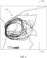
- a UAV may follow a flight path through a survey area, while detection sensors (e.g., of a portable gas analyzer) carried by the UAV collect measurements of the concentration of one or more gases of interest at points along the flight path.
- detection sensors e.g., of a portable gas analyzer
- the detection sensors also collect data regarding location (e.g., GPS data) and velocity (e.g., UAV velocity data, wind velocity data) corresponding to each gas concentration measurement.
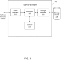
- FIG. 1 depicts a simplified block diagram of a computer system 100 in an exemplary embodiment.
- computer system 100 may be used for generating a gas leak detection visualization based upon an analysis of received sensor data, as described further herein.
- system 100 may include a visualization computing device 102 and a database server 104.
- Visualization computing device 102 may be in communication with one or more databases 106 (or other memory devices), detection sensors 108, and/or user devices 110.
- Database server 104 may be communicatively coupled to database 106 that stores data.
- database 106 may include map data, historical gas leak data, historical gas visualization data, etc.
- database 106 may be stored remotely from visualization computing device 102.
- database 106 may be decentralized.
- a user may access database 106 and/or visualization computing device via user device 110.
- Detection sensors 108 may be communicatively coupled with visualization computing device 102.
- detection sensors 108 may be associated with, or otherwise in communication with, a detection vehicle located proximate the site of the gas leak.
- detection sensors 108 may be coupled to an unmanned aerial vehicle (UAV) that takes measurements at the site of the gas leak.
- UAV unmanned aerial vehicle
- Detection sensors 108 may include any sensors associated with detecting and locating a gas leak.
- detection sensors 108 may include any of gas concentration sensors, global positioning system (GPS) sensors, wind sensors, height sensors, accelerometers, gyroscopes, and any other suitable sensors.
- GPS global positioning system
- Detection sensors 108 may be communicatively coupled to the Internet through many interfaces including, but not limited to, at least one of a network, such as the Internet, a local area network (LAN), a wide area network (WAN), or an integrated services digital network (ISDN), a dial-up-connection, a digital subscriber line (DSL), a cellular phone connection, and a cable modem.
- a network such as the Internet, a local area network (LAN), a wide area network (WAN), or an integrated services digital network (ISDN), a dial-up-connection, a digital subscriber line (DSL), a cellular phone connection, and a cable modem.
- user devices 110 may be communicatively coupled to visualization computing device 102 through many interfaces including, but not limited to, at least one of the Internet, a network, such as the Internet, a local area network (LAN), a wide area network (WAN), or an integrated services digital network (ISDN), a dial-up-connection, a digital subscriber line (DSL), a cellular phone connection, and a cable modem.
- a network such as the Internet, a local area network (LAN), a wide area network (WAN), or an integrated services digital network (ISDN), a dial-up-connection, a digital subscriber line (DSL), a cellular phone connection, and a cable modem.
- User devices 110 may be any device capable of accessing the Internet including, but not limited to, a desktop computer, a laptop computer, a personal digital assistant (PDA), a cellular phone, a smartphone, a tablet, a phablet, wearable electronics, smart watch, or other web-based connectable equipment or mobile devices.
- PDA
- KDE kernel density estimation
- implementation of the KDE calculation may require that the survey area be divided into a grid (e.g., 5000 x 5000), with each grid square having its own unique GPS coordinates or other numerical designation. These GPS coordinates or other numerical designations correspond to x and y in the formula below. Additionally, all n estimated source locations may have their own unique GPS coordinates or other numerical designations, and these GPS coordinates or other numerical designations correspond to x i and y i in the formula below.
- the summed value may be converted into a color or pattern, as described above, which forms the relevant KDE image.
- Some embodiments of the present disclosure may further utilize techniques for detecting and/or removing potential sampling bias from the data.
- Surveyors do not necessarily measure gas properties at all locations in an equal manner. Indeed, the number of detections in one area may outnumber the number of detections in another area simply because the analyzer remained in one area longer than the other area. This may artificially increase the point density in that area (a sampling bias), giving the impression that the probability associated with finding an emission location is incorrectly higher in one area than another.
- One technique that may be used to detect sampling bias is k-fold validation, in which the data is randomly separated into multiple subgroups, the smoothing algorithm is applied to each subgroup, and the error associated with the difference between the results from each subgroup provides an indication of the extent of sampling bias.
- sampling bias can be removed by calculating the likelihood that a kernel location was over-sampled and normalizing for the calculated sample density. For example, the expected origination path measurements looking upwind can be calculated (using either the local wind properties or a wind field model), and the amplitude of the kernel can then be normalized by the number of path measurements that are downwind. Since few or no wind paths will pass exactly through the emission point, nearby wind paths can be included with a weight that decreases with distance from the emission point.
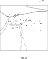
- the estimated gas source location data may first be binned into regular (or semi-regular) bins and then smoothed in the spatial dimensions. Additionally, it is contemplated that the KDE (or other) smoothing algorithm could be applied to the detection locations (i.e., points where the measured gas concentration exceeded a threshold) and/or to the spatial uncertainty ellipses (see FIG. 6 ) in a similar manner to the estimated gas source locations.
- An example technical effect of the system and methods described herein includes one or more of (a) receiving and analyzing gas leak sensor data; (b) optimizing a smoothing algorithm for visualizing gas leak sensor data; (c) providing a visualization of gas leak sensor data that is easily read; and (d) allowing users to quickly and efficiently locate and repair a gas leak source.
Landscapes
- Engineering & Computer Science (AREA)
- Radar, Positioning & Navigation (AREA)
- Remote Sensing (AREA)
- Physics & Mathematics (AREA)
- General Physics & Mathematics (AREA)
- Chemical & Material Sciences (AREA)
- Life Sciences & Earth Sciences (AREA)
- Health & Medical Sciences (AREA)
- Combustion & Propulsion (AREA)
- Computer Networks & Wireless Communication (AREA)
- Automation & Control Theory (AREA)
- Food Science & Technology (AREA)
- Medicinal Chemistry (AREA)
- Analytical Chemistry (AREA)
- Biochemistry (AREA)
- General Health & Medical Sciences (AREA)
- Immunology (AREA)
- Pathology (AREA)
- Examining Or Testing Airtightness (AREA)
Claims (15)
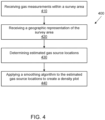
- Visualisierungssystem zum Visualisieren von Gasleckdetektionsdaten, umfassend einen Prozessor (205) in Kommunikation mit mindestens einer Speichervorrichtung (210), wobei der Prozessor zu Folgendem ausgelegt ist:Empfangen (410), von einem oder mehreren Sensoren (108), von Gasmessdaten für eine Vielzahl von Messorten innerhalb eines Untersuchungsbereichs (506), wobei die Gasmessdaten Gaskonzentrationsdaten umfassen;Empfangen (420), von der mindestens einen Speichervorrichtung (210), einer geografischen Darstellung des Untersuchungsbereichs (506);Bestimmen (430), basierend auf den Gasmessdaten, geschätzter Gasquellenorte (602, 702, 802) der Vielzahl von Messorten, wobei die geschätzten Gasquellenorte einen oder mehrere Messorte der Vielzahl von Messorten umfassen, an denen die Gaskonzentrationsdaten bei oder über einem Schwellenwert liegen; undVerwenden (440), durch einen Glättungsalgorithmus, von Punktdichtedaten der geschätzten Gasquellenorte (602, 702, 802), um ein mehrdimensionales Dichtediagramm (902, 1002, 1102, 1104, 1106) zu erzeugen.
- Visualisierungssystem nach Anspruch 1, wobei der Prozessor (205) ferner dazu ausgelegt ist, eine Grafik zu erzeugen, die das mehrdimensionale Dichtediagramm (902, 1002) umfasst, das auf die geografische Darstellung des Untersuchungsbereichs eingeblendet ist.
- Visualisierungssystem nach einem der vorhergehenden Ansprüche, wobei der eine oder die mehreren Sensoren (108) durch den Untersuchungsbereich (506) bewegt werden, und wobei der eine oder die mehreren Sensoren Gasmessungen an den mehreren Messorten durchführen, während der eine oder die mehreren Sensoren innerhalb des Untersuchungsbereichs bewegt werden.
- Visualisierungssystem nach einem der vorhergehenden Ansprüche, wobei die Gasmessdaten ferner mindestens eines von Daten eines globalen Positionsbestimmungssystems (GPS), die mit den Gasmessungen assoziiert sind, und Windgeschwindigkeitsdaten, die mit den Gasmessungen assoziiert sind, umfassen.
- Visualisierungssystem nach einem der vorhergehenden Ansprüche, wobei der Glättungsalgorithmus einen Kerndichteschätzungs(KDE)-Algorithmus mit einer Kernfunktion und einer Bandbreite umfasst,
wobei die Kernfunktion eine zweidimensionale Gauß-Funktion ist. - Visualisierungssystem nach Anspruch 5, wobei der Prozessor ferner zu Folgendem ausgelegt ist:Anpassen der Kernfunktion basierend auf einer lokalen Dichte der geschätzten Gasquellenorte; und/oder Anpassen der Kernfunktion basierend auf einem Unsicherheitswert, der mit den geschätzten Gasquellenorten assoziiert ist,wobei der Unsicherheitswert eine Schwankung von Windmessungen darstellt, die mit den geschätzten Gasquellenorten assoziiert sind.
- Visualisierungssystem nach Anspruch 6, wobei die Bandbreite eine feste Bandbreite ist, oder wobei die Bandbreite räumlich variiert wird, um einen Fehlerwert zu minimieren, der mit einer Kostenfunktion assoziiert ist, und wobei die Kostenfunktion ein mittlerer integrierter quadratischer Fehler ist; und/oder wobei sich die Bandbreite zwischen einer x-Dimension und einer y-Dimension unterscheidet.
- Visualisierungssystem nach einem der vorhergehenden Ansprüche, wobei der Prozessor ferner zu Folgendem ausgelegt ist:Gewichten jedes geschätzten Gasquellenorts vor dem Anwenden des Glättungsalgorithmus auf die jeweiligen geschätzten Gasquellenorte,wobei die Gewichtung jedes geschätzten Gasquellenorts eine Funktion der Gasmessdaten ist, die mit jedem geschätzten Gasquellenort assoziiert sind.
- Visualisierungssystem nach einem der vorhergehenden Ansprüche, wobei der Prozessor (205) ferner zu Folgendem ausgelegt ist:Detektieren einer Stichprobenverzerrung durch Anwenden einer k-fachen Validierung auf die geschätzten Gasquellenorte,wobei der Prozessor (205) ferner zu Folgendem ausgelegt ist:
Beseitigen der Stichprobenverzerrung durch Berechnen einer Wahrscheinlichkeit, dass ein Kernort überabgetastet wurde, und Normalisieren der berechneten Stichprobendichte. - Visualisierungssystem nach einem der vorhergehenden Ansprüche, wobei die geografische Darstellung mindestens eines eines Satellitenbilds und einer Straßenkarte umfasst.
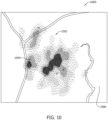
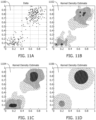
- Visualisierungssystem nach einem der vorhergehenden Ansprüche, wobei das mehrdimensionale Dichtediagramm (902, 1002, 1102, 1104, 1106) mindestens eines von mehreren Farben und mehreren Mustern umfasst, die unterschiedliche Wahrscheinlichkeiten eines Vorhandenseins einer Gasquelle anzeigen, und wobei transparente Regionen des mehrdimensionalen Dichtediagramms die niedrigste Wahrscheinlichkeit eines Vorhandenseins einer Gasquelle anzeigen.
- Computerimplementiertes Verfahren zum Visualisieren von Gasleckdetektionsdaten, wobei das computerimplementierte Verfahren durch ein Visualisierungssystem durchgeführt wird, das einen Prozessor (205) in Kommunikation mit mindestens einer Speichervorrichtung (210) umfasst, wobei das computerimplementierte Verfahren Folgendes umfasst:Empfangen (410), von einem oder mehreren Sensoren, von Gasmessdaten für eine Vielzahl von Messorten innerhalb eines Untersuchungsbereichs (506)), wobei die Gasmessdaten Gaskonzentrationsdaten umfassen;Empfangen (420), von der mindestens einen Speichervorrichtung, einer geografischen Darstellung des Untersuchungsbereichs (506);Bestimmen (430), basierend auf den Gasmessdaten, geschätzter Gasquellenorte (602, 702, 802) der mehreren Messorte, wobei die geschätzten Gasquellenorte einen oder mehrere Messorte der Vielzahl von Messorten umfassen, an denen die Gaskonzentrationsdaten bei oder über einem Schwellenwert liegen; undVerwenden (440), durch einen Glättungsalgorithmus, von Punktdichtedaten der geschätzten Gasquellenorte (602, 702, 802), um ein mehrdimensionales Dichtediagramm (902, 1002, 1102, 1104, 1106) zu erzeugen.
- Computerimplementiertes Verfahren nach Anspruch 12, das ferner Folgendes umfasst:
Erzeugen einer Grafik, die das mehrdimensionale Dichtediagramm (902, 1002) umfasst, das auf die geografische Darstellung des Untersuchungsbereichs eingeblendet ist. - Computerimplementiertes Verfahren nach Anspruch 12 oder 13, das durch das Visualisierungssystem nach einem der Ansprüche 1 bis 11 durchgeführt wird.
- Nichtflüchtiges computerlesbares Medium, auf dem computerausführbare Anweisungen verkörpert sind, wobei, bei Ausführung durch ein Visualisierungssystem, das einen Prozessor (205) in Kommunikation mit mindestens einer Speichervorrichtung (210) umfasst, die computerausführbaren Anweisungen den Prozessor zu Folgendem veranlassen:Empfangen (410), von einem oder mehreren Sensoren (108), von Gasmessdaten für eine Vielzahl von Messorten innerhalb eines Untersuchungsbereichs (506)), wobei die Gasmessdaten Gaskonzentrationsdaten umfassen;Empfangen (420), von der mindestens einen Speichervorrichtung, einer geografischen Darstellung des Untersuchungsbereichs (506);Bestimmen (430), basierend auf den Gasmessdaten, geschätzter Gasquellenorte (602, 702, 802) der Vielzahl von Messorten, wobei die geschätzten Gasquellenorte einen oder mehrere Messorte der Vielzahl von Messorten umfassen, an denen die Gaskonzentrationsdaten bei oder über einem Schwellenwert liegen; undVerwenden (440), durch einen Glättungsalgorithmus, von Punktdichtedaten der geschätzten Gasquellenorte, um ein mehrdimensionales Dichtediagramm (902, 1002, 1102, 1104, 1106) zu erzeugen.
Applications Claiming Priority (1)
| Application Number | Priority Date | Filing Date | Title |
|---|---|---|---|
| US202163185344P | 2021-05-06 | 2021-05-06 |
Publications (2)
| Publication Number | Publication Date |
|---|---|
| EP4086602A1 EP4086602A1 (de) | 2022-11-09 |
| EP4086602B1 true EP4086602B1 (de) | 2025-07-02 |
Family
ID=81585284
Family Applications (1)
| Application Number | Title | Priority Date | Filing Date |
|---|---|---|---|
| EP22172066.7A Active EP4086602B1 (de) | 2021-05-06 | 2022-05-06 | Technologien zur verbesserten darstellung von gasleckdetektionsdaten |
Country Status (4)
| Country | Link |
|---|---|
| US (1) | US20220357231A1 (de) |
| EP (1) | EP4086602B1 (de) |
| CN (1) | CN115307826A (de) |
| ES (1) | ES3041469T3 (de) |
Families Citing this family (17)
| Publication number | Priority date | Publication date | Assignee | Title |
|---|---|---|---|---|
| US12399164B2 (en) | 2018-06-19 | 2025-08-26 | Seekops Inc. | Emissions estimate model algorithms and methods |
| US12449409B2 (en) | 2018-06-19 | 2025-10-21 | Seekops Inc. | Emissions estimate model algorithms and methods |
| WO2019246283A1 (en) | 2018-06-19 | 2019-12-26 | Seekops Inc. | Localization analytics algorithms and methods |
| EP3830533A4 (de) | 2018-07-30 | 2022-04-20 | SeekOps Inc. | Ultraleichte handvorrichtung zur detektion von gasleckagen |
| EP3870951A4 (de) | 2018-10-22 | 2022-07-27 | SeekOps Inc. | Hochbreitbandiger, leichter punktsensor auf uav zur quantifizierung von treibhausgasen in atmosphärischen schichten |
| EP3948202A4 (de) | 2019-04-05 | 2023-01-04 | SeekOps Inc. | Zeit- und dateneffiziente leckdetektionsbestätigung |
| WO2021026215A1 (en) | 2019-08-05 | 2021-02-11 | Seekops Inc. | Rapidly deployable uas system for autonomous inspection operations using a combined payload |
| US12392680B2 (en) | 2019-09-20 | 2025-08-19 | Seekops Inc. | Spectral fitting of compact laser-based trace gas sensor measurements for high dynamic range (HDR) |
| US12197233B2 (en) * | 2019-10-04 | 2025-01-14 | Seekops Inc. | Closed surface flight pattern generation for unmanned aerial vehicle (UAV) flux plane assessment of large facilities |
| US12055485B2 (en) | 2020-02-05 | 2024-08-06 | Seekops Inc. | Multispecies measurement platform using absorption spectroscopy for measurement of co-emitted trace gases |
| WO2021158916A1 (en) | 2020-02-05 | 2021-08-12 | Seekops Inc. | Multiple path length optical cell for trace gas measurement |
| EP4182766A4 (de) | 2020-07-17 | 2024-06-26 | SeekOps Inc. | Aas-arbeitsübung |
| US11748866B2 (en) | 2020-07-17 | 2023-09-05 | Seekops Inc. | Systems and methods of automated detection of gas plumes using optical imaging |
| WO2022093864A1 (en) | 2020-10-27 | 2022-05-05 | Seekops Inc. | Methods and apparatus for measuring methane emissions with an optical open-cavity methane sensor |
| US12050155B2 (en) * | 2022-03-03 | 2024-07-30 | Abb Schweiz Ag | Method for estimating flux using handheld gas sensors and an inertial measurement unit |
| US12333921B2 (en) * | 2023-06-08 | 2025-06-17 | Saudi Arabian Oil Company | Unmanned aerial system for autonomous gas leakage detection, quantification, and mitigation |
| CN119224242B (zh) * | 2024-12-03 | 2025-04-08 | 浙江省应急管理科学研究院(浙江省安全生产技术检测检验中心、浙江省危险化学品登记中心) | 一种危险作业场所的气体检测方法及系统 |
Citations (1)
| Publication number | Priority date | Publication date | Assignee | Title |
|---|---|---|---|---|
| US20200149883A1 (en) * | 2015-10-06 | 2020-05-14 | Bridger Photonics, Inc. | Gas-mapping 3d imager measurement techniques and method of data processing |
Family Cites Families (5)
| Publication number | Priority date | Publication date | Assignee | Title |
|---|---|---|---|---|
| EP3225966B1 (de) * | 2016-03-31 | 2020-04-22 | Konica Minolta Laboratory U.S.A., Inc. | Laser scanning leak detection und visualisierung vorrichtung |
| CN107917341B (zh) * | 2016-10-09 | 2020-01-07 | 中国石油天然气股份有限公司 | 一种输油管道泄漏检测方法及装置 |
| WO2018231735A1 (en) * | 2017-06-12 | 2018-12-20 | Flir Systems Ab | System and method for quantifying a gas leak |
| US12399164B2 (en) * | 2018-06-19 | 2025-08-26 | Seekops Inc. | Emissions estimate model algorithms and methods |
| EP3948202A4 (de) * | 2019-04-05 | 2023-01-04 | SeekOps Inc. | Zeit- und dateneffiziente leckdetektionsbestätigung |
-
2022
- 2022-05-06 US US17/738,533 patent/US20220357231A1/en active Pending
- 2022-05-06 CN CN202210488541.8A patent/CN115307826A/zh active Pending
- 2022-05-06 ES ES22172066T patent/ES3041469T3/es active Active
- 2022-05-06 EP EP22172066.7A patent/EP4086602B1/de active Active
Patent Citations (1)
| Publication number | Priority date | Publication date | Assignee | Title |
|---|---|---|---|---|
| US20200149883A1 (en) * | 2015-10-06 | 2020-05-14 | Bridger Photonics, Inc. | Gas-mapping 3d imager measurement techniques and method of data processing |
Also Published As
| Publication number | Publication date |
|---|---|
| CN115307826A (zh) | 2022-11-08 |
| US20220357231A1 (en) | 2022-11-10 |
| ES3041469T3 (en) | 2025-11-12 |
| EP4086602A1 (de) | 2022-11-09 |
Similar Documents
| Publication | Publication Date | Title |
|---|---|---|
| EP4086602B1 (de) | Technologien zur verbesserten darstellung von gasleckdetektionsdaten | |
| US10962437B1 (en) | Aggregate leak indicator display systems and methods | |
| US10444108B1 (en) | Systems and methods for likelihood-based detection of gas leaks using mobile survey equipment | |
| CA2455359C (en) | System, computer program and method for 3d object measurement, modeling and mapping from single imagery | |
| US20180101175A1 (en) | System and method for tracking pollution | |
| EP2956801B1 (de) | Positionierung in strassenschluchten | |
| US8817093B2 (en) | Photogrammetric networks for positional accuracy | |
| CN119720867A (zh) | 基于无人船的危化品泄露扩散预测方法、系统及存储介质 | |
| CN102156796B (zh) | 用于使用多个风力资源网格来确定风况的装置和方法 | |
| US9679399B2 (en) | Method to optimize the visualization of a map's projection based on data and tasks | |
| JP7285678B2 (ja) | 情報処理装置、及び制御プログラム | |
| Miky et al. | A combined contour lines iteration algorithm and Delaunay triangulation for terrain modeling enhancement | |
| US10546418B2 (en) | Visualization of positional geospatial uncertainty | |
| Chen et al. | A total error-based multiquadric method for surface modeling of digital elevation models | |
| Downs et al. | Adaptive-velocity time-geographic density estimation for mapping the potential and probable locations of mobile objects | |
| CN107085230A (zh) | 一种自动化海域使用监测系统及方法 | |
| CN120871165A (zh) | 地震勘探路径规划方法、系统、设备及介质 | |
| Lohani et al. | Effect of data density, scan angle, and flying height on the accuracy of building extraction using LiDAR data | |
| Dewali et al. | A GPS-based real-time avalanche path warning and navigation system | |
| CN120125667B (zh) | 一种桥梁形变监测方法及装置 | |
| Klein | Geospatial internet of things: Framework for fugitive methane gas leaks monitoring | |
| Widyaningrum | Challenges and Opportunities: One Stop Processing of Automatic Large-Scale Base Map Production Using Airborne Lidar Data Within Gis Environment. Case Study: Makassar City, Indonesia | |
| Xu et al. | An improved pixel counting method for arbitrary zonal statistics on GlobeLand30 | |
| Khaleghi | Lagrangian back-trajectory dispersion and mass balance models for methane emission localization and quantification | |
| CN120409265A (zh) | 一种基于数据模型双驱动的水污染预测方法和装置 |
Legal Events
| Date | Code | Title | Description |
|---|---|---|---|
| PUAI | Public reference made under article 153(3) epc to a published international application that has entered the european phase |
Free format text: ORIGINAL CODE: 0009012 |
|
| STAA | Information on the status of an ep patent application or granted ep patent |
Free format text: STATUS: THE APPLICATION HAS BEEN PUBLISHED |
|
| AK | Designated contracting states |
Kind code of ref document: A1 Designated state(s): AL AT BE BG CH CY CZ DE DK EE ES FI FR GB GR HR HU IE IS IT LI LT LU LV MC MK MT NL NO PL PT RO RS SE SI SK SM TR |
|
| STAA | Information on the status of an ep patent application or granted ep patent |
Free format text: STATUS: REQUEST FOR EXAMINATION WAS MADE |
|
| 17P | Request for examination filed |
Effective date: 20230509 |
|
| RBV | Designated contracting states (corrected) |
Designated state(s): AL AT BE BG CH CY CZ DE DK EE ES FI FR GB GR HR HU IE IS IT LI LT LU LV MC MK MT NL NO PL PT RO RS SE SI SK SM TR |
|
| GRAP | Despatch of communication of intention to grant a patent |
Free format text: ORIGINAL CODE: EPIDOSNIGR1 |
|
| STAA | Information on the status of an ep patent application or granted ep patent |
Free format text: STATUS: GRANT OF PATENT IS INTENDED |
|
| INTG | Intention to grant announced |
Effective date: 20250124 |
|
| GRAS | Grant fee paid |
Free format text: ORIGINAL CODE: EPIDOSNIGR3 |
|
| GRAA | (expected) grant |
Free format text: ORIGINAL CODE: 0009210 |
|
| STAA | Information on the status of an ep patent application or granted ep patent |
Free format text: STATUS: THE PATENT HAS BEEN GRANTED |
|
| AK | Designated contracting states |
Kind code of ref document: B1 Designated state(s): AL AT BE BG CH CY CZ DE DK EE ES FI FR GB GR HR HU IE IS IT LI LT LU LV MC MK MT NL NO PL PT RO RS SE SI SK SM TR |
|
| REG | Reference to a national code |
Ref country code: GB Ref legal event code: FG4D |
|
| REG | Reference to a national code |
Ref country code: CH Ref legal event code: EP |
|
| REG | Reference to a national code |
Ref country code: DE Ref legal event code: R096 Ref document number: 602022016699 Country of ref document: DE |
|
| REG | Reference to a national code |
Ref country code: IE Ref legal event code: FG4D |
|
| REG | Reference to a national code |
Ref country code: NL Ref legal event code: MP Effective date: 20250702 |
|
| REG | Reference to a national code |
Ref country code: ES Ref legal event code: FG2A Ref document number: 3041469 Country of ref document: ES Kind code of ref document: T3 Effective date: 20251112 |
|
| PG25 | Lapsed in a contracting state [announced via postgrant information from national office to epo] |
Ref country code: PT Free format text: LAPSE BECAUSE OF FAILURE TO SUBMIT A TRANSLATION OF THE DESCRIPTION OR TO PAY THE FEE WITHIN THE PRESCRIBED TIME-LIMIT Effective date: 20251103 |
|
| PG25 | Lapsed in a contracting state [announced via postgrant information from national office to epo] |
Ref country code: NL Free format text: LAPSE BECAUSE OF FAILURE TO SUBMIT A TRANSLATION OF THE DESCRIPTION OR TO PAY THE FEE WITHIN THE PRESCRIBED TIME-LIMIT Effective date: 20250702 |
|
| REG | Reference to a national code |
Ref country code: AT Ref legal event code: MK05 Ref document number: 1809695 Country of ref document: AT Kind code of ref document: T Effective date: 20250702 |
|
| PG25 | Lapsed in a contracting state [announced via postgrant information from national office to epo] |
Ref country code: IS Free format text: LAPSE BECAUSE OF FAILURE TO SUBMIT A TRANSLATION OF THE DESCRIPTION OR TO PAY THE FEE WITHIN THE PRESCRIBED TIME-LIMIT Effective date: 20251102 |
|
| REG | Reference to a national code |
Ref country code: LT Ref legal event code: MG9D |
|
| PG25 | Lapsed in a contracting state [announced via postgrant information from national office to epo] |
Ref country code: AT Free format text: LAPSE BECAUSE OF FAILURE TO SUBMIT A TRANSLATION OF THE DESCRIPTION OR TO PAY THE FEE WITHIN THE PRESCRIBED TIME-LIMIT Effective date: 20250702 |
|
| PG25 | Lapsed in a contracting state [announced via postgrant information from national office to epo] |
Ref country code: FI Free format text: LAPSE BECAUSE OF FAILURE TO SUBMIT A TRANSLATION OF THE DESCRIPTION OR TO PAY THE FEE WITHIN THE PRESCRIBED TIME-LIMIT Effective date: 20250702 |
|
| PG25 | Lapsed in a contracting state [announced via postgrant information from national office to epo] |
Ref country code: HR Free format text: LAPSE BECAUSE OF FAILURE TO SUBMIT A TRANSLATION OF THE DESCRIPTION OR TO PAY THE FEE WITHIN THE PRESCRIBED TIME-LIMIT Effective date: 20250702 |
|
| PG25 | Lapsed in a contracting state [announced via postgrant information from national office to epo] |
Ref country code: GR Free format text: LAPSE BECAUSE OF FAILURE TO SUBMIT A TRANSLATION OF THE DESCRIPTION OR TO PAY THE FEE WITHIN THE PRESCRIBED TIME-LIMIT Effective date: 20251003 |
|
| PG25 | Lapsed in a contracting state [announced via postgrant information from national office to epo] |
Ref country code: SE Free format text: LAPSE BECAUSE OF FAILURE TO SUBMIT A TRANSLATION OF THE DESCRIPTION OR TO PAY THE FEE WITHIN THE PRESCRIBED TIME-LIMIT Effective date: 20250702 Ref country code: CZ Free format text: LAPSE BECAUSE OF FAILURE TO SUBMIT A TRANSLATION OF THE DESCRIPTION OR TO PAY THE FEE WITHIN THE PRESCRIBED TIME-LIMIT Effective date: 20250702 |
|
| PG25 | Lapsed in a contracting state [announced via postgrant information from national office to epo] |
Ref country code: LV Free format text: LAPSE BECAUSE OF FAILURE TO SUBMIT A TRANSLATION OF THE DESCRIPTION OR TO PAY THE FEE WITHIN THE PRESCRIBED TIME-LIMIT Effective date: 20250702 |
|
| PG25 | Lapsed in a contracting state [announced via postgrant information from national office to epo] |
Ref country code: BG Free format text: LAPSE BECAUSE OF FAILURE TO SUBMIT A TRANSLATION OF THE DESCRIPTION OR TO PAY THE FEE WITHIN THE PRESCRIBED TIME-LIMIT Effective date: 20250702 Ref country code: PL Free format text: LAPSE BECAUSE OF FAILURE TO SUBMIT A TRANSLATION OF THE DESCRIPTION OR TO PAY THE FEE WITHIN THE PRESCRIBED TIME-LIMIT Effective date: 20250702 |
|
| PG25 | Lapsed in a contracting state [announced via postgrant information from national office to epo] |
Ref country code: RS Free format text: LAPSE BECAUSE OF FAILURE TO SUBMIT A TRANSLATION OF THE DESCRIPTION OR TO PAY THE FEE WITHIN THE PRESCRIBED TIME-LIMIT Effective date: 20251002 |