EP4086552A1 - Scheduling management system for integrated steel plant - Google Patents
Scheduling management system for integrated steel plant Download PDFInfo
- Publication number
- EP4086552A1 EP4086552A1 EP21172043.8A EP21172043A EP4086552A1 EP 4086552 A1 EP4086552 A1 EP 4086552A1 EP 21172043 A EP21172043 A EP 21172043A EP 4086552 A1 EP4086552 A1 EP 4086552A1
- Authority
- EP
- European Patent Office
- Prior art keywords
- ladle
- time
- crane
- metallurgical facility
- schedule
- Prior art date
- Legal status (The legal status is an assumption and is not a legal conclusion. Google has not performed a legal analysis and makes no representation as to the accuracy of the status listed.)
- Withdrawn
Links
Images




Classifications
-
- F—MECHANICAL ENGINEERING; LIGHTING; HEATING; WEAPONS; BLASTING
- F27—FURNACES; KILNS; OVENS; RETORTS
- F27D—DETAILS OR ACCESSORIES OF FURNACES, KILNS, OVENS OR RETORTS, IN SO FAR AS THEY ARE OF KINDS OCCURRING IN MORE THAN ONE KIND OF FURNACE
- F27D19/00—Arrangements of controlling devices
-
- F—MECHANICAL ENGINEERING; LIGHTING; HEATING; WEAPONS; BLASTING
- F27—FURNACES; KILNS; OVENS; RETORTS
- F27D—DETAILS OR ACCESSORIES OF FURNACES, KILNS, OVENS OR RETORTS, IN SO FAR AS THEY ARE OF KINDS OCCURRING IN MORE THAN ONE KIND OF FURNACE
- F27D21/00—Arrangement of monitoring devices; Arrangement of safety devices
Definitions
- the present disclosure generally relates to scheduling management system for an integrated steel plant. More particularly to a system and a method for automatically scheduling operations in a melt shop of the integrated steel plant.
- Integrated steel plants are large throughput industries producing liquid melt and solidified products thereof, in order of million metrictonnes per annum (MMPTA).
- MMPTA million metrictonnes per annum
- Examples of such production process may include a casting process that is serviced typically by a melt shop employing multiple operations such as, for example, a basic oxygen furnaces (BOF) to make hot steel compositions for casting.
- BOF basic oxygen furnaces
- the liquid melt or molten metal
- Other operation of the melt shop includesa process of degassing.
- the melt shop and operations associated with the melt shop forms a heart of the integrated steel plant.
- melt shop In order to perform the production process comprising aforementioned meltshop operations, the melt shop is facilitated with multiple metallurgical facility station that are designed and configured to obtain the desired casting product. Further, a vessel called “ladle” is used to assist in aforementioned melt shop operations i.e., it is the ladle that encompasses the molten metal, weighing anywhere between approximately 100 to 250 tonnes, and iscarried between multiple metallurgical facility stations using a crane for performing the melt shop operations.
- Example of metallurgical facility station can be a slag pot. Lancing stand, ladle furnace and a caster.
- the site supervisor decides which metallurgical facility station the ladle must be procured from, and where it should be moved to for subsequent processing. Along similar lines is the decision taken by the site supervisor to assign a particular crane among available cranes, to achieve a ladle-transfer. Near-sighted choices of metallurgical facility station for ladle pick-up/drop-off, and of the cranes (which cannot cross over each other) for ladle-transport often lead to longer idle times of the metallurgical facility station/cranes.
- the inventors of the present invention have realized, after inventive and insightful reasoning that there are envisioned problemsas more and more ladle transfer optimization needs to be realized in the future market as discussed above and below.
- a first aspect is a computer-implemented method for scheduling melt shop operations in an integrated steel plant.
- the method comprising detecting an operational event associated with said melt shop, where said operational event is detected in real-time. Once, the operational event is detected, the method comprises determining an availability of at least one metallurgical facility station from plurality of metallurgical facility stations, at least one crane and said at least one ladle.
- the method further comprises identifying a plurality of tasks, where each task comprises an estimated pick-up time of said at least one ladle from said at least one metallurgical facility station and an estimated drop-off time of said at least one ladle to at least one another metallurgical facility station from said plurality of metallurgical facility stations.
- the method further comprises gene rating a schedule comprising identification of a crane to perform said at least one task with an updated estimated pick-uptime and drop-off time of said at least one task.
- the method further comprises providing a notification indicatingsaid schedule to an electronic device.
- the present disclosure aims to reduce a manual decision-making during melt shop operation. Instead of the manual decision-making, the present disclosure provides the method that relies on a systematic approach that forecasts ladle-availabilities/requirements and generates an optimal/near-optimal plan for ladle movements and crane trajectories along a bay of the melt shop. In addition to reducing the manual decision-making, the present disclosure also seeks to eliminate the communication (and the associated pitfalls) otherwise necessary between the metallurgical facility stations-operators, the supervisor, on-ground personnel and crane-operators, and providesan automated optimal/near-optimal operationof cranes.
- the proposed method/system significantly reduces on-ground personnel-presence-and-movement along the melt shop to monitor metallurgical facility stations/ladles/cranes otherwise required for manual scheduling, and therefore, enhances the safety of operators/supervisors in the melt shop.
- the present disclosure provides a solution which seeks to mitigate, alleviate, or eliminate one or more of the above-identified deficiencies in the art and disadvantages singly or in any combination and to provide solutions comprising a system for scheduling operations in the melt shop.
- the operations such as, for example, ladle transfers in the melt shop on available cranes in order to improve the melt shop productivity and energy efficiency by an organized utilization of cranes and processing metallurgical facility stations.
- the operational event comprises at least one of a) time indication that an operation of said at least one ladle at any of said metallurgical facility station is about to complete b) detection of at least one signal indicating operational status of said at least one metallurgical facility station, wherein said operational status comprising at least one of: Ladle Furnace start time and end time, Electric Arc Furnace start time and end time, Basic Oxygen Furnace start time and end time, Ladle Furnace arcing start time and end time, Electric Arc Furnace arcing start time and endtime,Turret rotation, Teeming start time, Teeming endtime, pick-up time and drop time of said at least one ladle, and an availability of said at least one ladle, c) deviation in real-time operationfrom priorschedule d) change in maintenance status of said at least one available metallurgical facility station and said at least one crane e) emergence of unplanned pick-up and drop-off operations by said at least one crane
- said fixed parameters comprises at least one of crane specification information comprising total number of cranes, width of each crane and speed information of each crane, inter-crane separations, metallurgical facility station specification information comprising at least one of location of said at least one metallurgical facility station, maximum ladle-carrying capacity and grade-wise ladle-processing time of said at least one metallurgical facility station, and bay information of said melt shop comprising at least one of a length, width and grade-dependent sequence of operation of said at least one ladle.
- the method for determining the availability of said at least one crane comprises categorizing a plurality of cranes of said melt shop into at least one of in-operational cranes, in-operational cranes in scheduling horizon, operational cranes, busy cranes and idle cranes, wherein said in-operational cranes are based on at least one operational event and scheduling horizon of at least one crane and determining availability of said at leastone crane from said categorized plurality of cranes.
- the method further comprises gene rating at least one criteria for at least one crane to perform said tasks.
- the at least one criteria indicatesthat (a) each ladle to remain at said at least one metallurgical facility station for a pre-defined duration prior to pick-up, (b) said at least one metallurgical facility station to accommodate said at least one ladle based on operational characteristics comprising at least one of capacity, a grade of steel casting process, cross-section of at least one of said metallurgical facility station, and (c) said each ladle to follow pre-defined processing sequence.
- the method further comprises obtaining crane trajectories based on at least one crane-trajectory criteria comprising (a) a pre-defined crane velocities in a pre-determined direction, (b) a pre-defined separation between at least two adjacent cranes, and (c) a pre-defined period of ladle-handling by each said crane.
- the crane identification comprises performing a permutation of a sequence order in which said plurality of tasks are assigned to each said crane.
- the at least one operational event is detected in real-time by using a tracking system configured to monitor said operational event of said melt shop.
- the method comprises receiving a first request indicating one of a change in at least one parameterfrom said at least one identified task and create at leastone new task.
- said at least one parameter comprises said estimated pick-up time of said at least one ladle from said at least one metallurgical facility station and said estimated drop-off time of said at least one ladle at said at least one another metallurgical facility station, or creating said at least one new task based on said request, where said at least one new task comprises a new estimated pick-up time of at least one ladle from said at least one metallurgical facility station and a new estimated drop-off time of said at least one ladle to said at least one another metallurgical facility station.
- the method further comprises receiving a second request indicating one of a change in schedule comprising said at least one identification of at least one crane to perform said at least one task or create a new schedule comprising at least one new identification of said at least one crane to perform said at least one task and generate a new schedule or modify the schedule in response to said second request.
- the scheduler unit can be further configured to provide an estimate of a processing time information to an external heat determination unit configured to determine heating requirement for said at least one ladleat said at least one metallurgicalfacility station.
- said plurality of tasks and generated schedule is based on a moving horizon estimation.
- a second aspect is a scheduling management system for meltshop operations in an integrated steel plant comprising plurality of ladles, a plurality of metallurgical facility stations, and a plurality of cranes for transporting at least one ladle between said pluralities of metallurgical facility stations.
- the scheduling management system comprises an event detection unit configured to detect an operational event associated with said melt shop, where said operational event is detected in real-time. Once, the operational event is detected, a status monitoring unit is triggered and is configured to determine an availability of at least one metallurgical facility station, at least one crane and said at least one ladle.
- the scheduling management system further comprises a task management unit configured to identify a plurality of tasks, where each task comprises an estimated pick-uptime of said at leastone ladle from said at least one metallurgical facility station and an estimated drop-off time of said at least one ladle to at least one another metallurgical facility station from said plurality of metallurgical facility stations.
- the scheduling management system further comprises a scheduler unit configured to generate a schedule comprising identification of a crane to perform said at least one task with an updated estimated pick-uptime and drop-off time of said at least one task.
- the scheduling management system further comprises a notification unit configured to provide a notification indicating said schedule to an electronic device.
- some embodiments improves the efficiency and productivity of the melt shop operations.
- some embodiments optimizes ladle movements to select their destination and then optimizes crane movements to predict their trajectories in nearfuture.
- Some of the example embodiments presented herein are directed towards system and method for automatically scheduling ladle movements and crane movements between the pluralities of metallurgical facility stations. As part of the development of the example embodiments presented herein, a problem will first be identified and discussed.
- a liquid melt undergoes variety of operations (basic oxygen furnaces (BOF), desulphurization, ladle metallurgy, degassing, etc.). All these operations priorto production process (such as casting) are batch processes carried out forthe ladle of typically 100-250 tonnes. Each batch process requires the ladle accommodating a liquid meltweighingin range of hundredsof tonnesto be transported from one metallurgical facility station to another metallurgical facility station. With the liquid melt typically being more than 1000 degree centigrade above surrounding, any ladle transport involves large heat losses. Thus, a time for ladle and crane movements is very critical. That is, the ladle and crane movements within minimum time avoids (i) unnecessary heat loss, (ii) unnecessary idle-time of downstream units and (iii) lowered quality of cast product.
- BOF basic oxygen furnaces
- desulphurization ladle metallurgy
- degassing etc.
- All these operations priorto production process are batch processes carried out forthe ladle of typically 100-250 tonnes
- some embodiments, of the present disclosure provides an automatic scheduling of the ladle and crane movements that avoids (i) unnecessary heat loss, (ii) unnecessary idle-time of downstream units and (iii) lowering quality of cast product.
- a melt/melting shop layout (hereinafter referred to as "melt shop") 200 generally comprises a plurality of metallurgical facility stations 220a-220e (can be used interchangeably with the term metallurgical facility station(s) 220), a plurality of ladles 230a-230b (can be used interchangeably with the term ladle(s) 230), and a plurality of cranes 240a-240e (can be used interchangeably with the term crane(s) 240) for lifting and carrying at least one ladle 230.
- metallurgical facility stations herein refers to equipments arranged for processing liquid iron/melt or molten metal for producing a solidified product, for example, steel.
- These equipments can be, for example, melting furnace 220a, a lancing stand 220b, refining facility station 220c, a caster 220d and at least one slag pot 220e, or even vehicles like transfer cars or stands that can act as placeholders for ladles.
- the melt shop 200 is governed by steel plant limitations, product requirements and several other factors, the ladle 230 containing the liquid melt needs to be transferred between the pluralities of metallurgical facility stations 220.
- the ladle 230 refers to a "vessel" containing molten metal obtained from the blast furnace and may weigh anywhere between approximately 100 to 250 tonnes.
- the transfer of the ladle 230 is carried out using the cranes 240. While the transfer of the ladle 230 may also be carried using transfercars, however, the transfer cars are limited in terms of functionality as they can travel in only one dimension and the cranes 240 can move in three dimensions.
- the meltingfurnace 220a can be of electricarc type such as electric arc furnace (EAF) or oxygen type such as basic oxygen furnace (BOF). It is merely for demonstration purpose that BOF has been considered herein but it is not limited thereto and any other melting furnace can be applied in context of the present disclosure.
- EAF electric arc furnace
- BOF basic oxygen furnace
- the molten metal from the at least one melting furnace 220a is transferred via the ladle 230 to the refining facility station 220c for metallurgical treatment.
- the refining facility station 220c may be used to provide secondary processing facility for adding small amounts of metallurgical agents into the ladle 230containingthe molten metal, bubbling with argon gas, and stirring, as well as heating to a desired casting or holding temperature.
- the refining facility station 220c can be referto ladle metallurgical facility (furnace), LMF or a ladle furnace, LF. Further, the refined molten metal from the refining facility station 220c is transferred via the ladle 230 to the at least one caster 220d for casting process so as to obtain continuous supply of steel. Similarly, the empty ladle 230 as well as slag vessels are suitably transported to the slag pot 220e for further processing such as, for example, cleaning.
- the ladle 230 Prior to transferring of the ladle 230 to any of the melting furnaces 220a, the ladle 230 is stocked at the lancing stand 220b for lancing a surface of the ladle 230 according to the product requirements or as required by supervisors of the melt shop 200.
- melt shop operations (BOF, lancing, ladle metallurgy, slag disposal, etc.) carried out at different metallurgical facility stations 220 and corresponding movements to be carried out in the melt shop 200 using the ladle 230 and cranes 240.
- the present disclosure provides a scheduling management system 260 for automatically scheduling the movement of ladle 230 and the cranes 240 between different metallurgical facility stations 220.
- the scheduling management system 260 thus aidsin increasing the productivity and capital cost of the melt shop 200 by saving the precioustime and energy, otherwise required in the scheduled movement as shown in FIG.1 .
- the schedule generated from the scheduling management system 260 is based on several factors such as operational events/activities associated with the melt shop 200. These operational events/activities are detected in real-time by a tracking system 250.
- the tracking system 250 can be a live tracking system that is placed within the melt shop 200. The placement of the tracking system 250 within the melt shop 200 is such that it can facilitate monitoring of various operational events/activities of the melt shop 200.
- the scheduling management system 260 can communicate with the tracking system 250 to receive the real-time operational events/activities.
- the scheduling management system 260 can be configured to generate the schedule for the automatic movement of ladle 230 and cranes 240 between the metallurgical facility stations 220 using the operational events/activities.
- the tracking system 250 can be, for example, any electronic device configured with sensors including (but not limited to) a camera and an accelerometer.
- the input to the scheduling management system 260 can be directly received/obtained from industrial controllers such as for example, a distributed control system (DCS), a programmable logic controller (PLC), proportional-integral-derivative (PID) controllers, etc.
- industrial controllers such as for example, a distributed control system (DCS), a programmable logic controller (PLC), proportional-integral-derivative (PID) controllers, etc.
- the scheduling management system 260 provides superior operational efficiency of the melt shop 200. Further, the ladle 230 circulation/movements is achieved with lower cycle-times leadingto reduced time-duration of maintaining desired temperatures of the molten contents of the ladle 230 while in circulation, therefore, improving energy efficiency of the melt shop 200.
- the scheduling management system 260 reduces the need of human engagement for the melt shop operations (as shown in FIG.1 ): dedicated on-ground personnel for monitoring the cranes 240 and communication there between, the metallurgical facility stations 220 availability and central supervisor for decision-making related to ladle-transport.
- the scheduling management system 260 is provided to generate an optimal/near-optimal schedule that simultaneously identifies the pick-up/drop-off metallurgical facility stations 220 for the ladles 230 along with specificcrane (for example, the crane 240) for performing such transfers of the ladles 230 at designated times.
- specificcrane for example, the crane 240
- a networkenvironment300 may include a server 301, a network(s) 305, and devices 270.1-270.n (hereinafter referred as the electronic device 270). Further, the server 301 includes a database 302, the scheduling management system 260, and a network interface(s) 304.
- the server 301 comprising the scheduling management system 260 communicates with the electronic device 270 using the network 305.
- the electronic device 270 may be referred to as for e.g., central computer/control system configured to remotely manage (by the central supervisor or field operator) the operations of the melt shop 200.
- the instructions obtained from the scheduling management system 260 may be communicated directly to the crane 240, provided that the crane 240 is configured with a circuitry that is capable of receiving and processing the instructions received from the scheduling management system 260.
- the electronic device 270 may be a device having a screen and capable of performing human-machine interaction, such as a mobile phone, notebook computer, tablet, desktop computer, orthe like.
- the server 301 may include hardware, software, or firmware components.
- the database 302 may be a centralized database located remotely to the melt shop 200 and can be accessed by the scheduling management system 260 using the network 305.
- the database 302 may include one or more parameters (e.g., fixed parameters) related to the melt shop 200 or related to the metallurgical facility stations 220, the ladle 230 and the crane 240.
- the database 302 may include information related to maintenance status of the crane 240, maintenance status of said metallurgical facility 220, and information regarding the criteria forthe crane 240.
- the database 302 can also be accessed by the tracking system 250.
- the network interface 304 via which the scheduling management system 260 may communicate with one or more other devices or systems via the network 305.
- the scheduling management system 260 can be configured to remotely communicate with display devices (to display the schedule) installed and/or being operated at the melt shop 200, using the network interface 304 supported in both the scheduling management system 260 and the display devices.
- the network 305 may include, but are not limited to, anyone or more different types of communications networks such as, for example, cable networks, public networks (e.g., the Internet), private networks (e.g., frame-relay networks), wireless networks, cellular networks, telephone networks (e.g., a public switched telephone network), cloud based networks, or any other suitable private or public packet switched or circuit switched networks.
- Such network(s) may have any suitable communication range associated therewith and may include, for example, global networks (e.g., the Internet), metropolitan area networks (MANs), wide area networks (WANs), local area networks(LANs), or personal area networks (PANs).
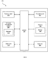
- the computing environment 400 may be referred to as the electronic device 270 (as defined herein).
- the computing environment 400 may include a processing unit 401, one or more memory devices402 (referred to herein as memory 402), storage unit 403, an input unit 404, and an output unit405.
- the computing environment 400 may further include one or more buses 406 that functionally couple various components of the computing environment 400.
- the memory 402 may include the information related to the fixed parameters of the melt shop 200.
- the fixed parameters indicating the specification of the metallurgical facility stations 220, the ladles 230 and the cranes 240 along with bay related information of the melt shop 200.
- the memory 402 may also include any information regarding prior schedule (if any).
- the memory 402 may include volatile memory (memory that maintains its state when supplied with power) such as random access memory (RAM) and/or non-volatile memory (memory that maintains its state even when not supplied with power) such as read-only memory (ROM), flash memory, ferroelectric RAM (FRAM), and so forth.
- Persistent data storage may include non-volatile memory.
- volatile memory may enable faster read/write access than non-volatile memory.
- certain types of non-volatile memory e.g., FRAM
- FRAM non-volatile memory
- the storage unit 403 may be equivalent to the memory 402.
- the memory 402 may include multiple different types of memory such as various types of static random access memory (SRAM), various types of dynamic random access memory (DRAM), various types of unalterable ROM, and/or writeable variants of ROM such as electrically erasable programmable read-only memory (EEPROM), flash memory, and so forth.
- SRAM static random access memory
- DRAM dynamic random access memory
- EEPROM electrically erasable programmable read-only memory
- flash memory and so forth.
- the memory 402 may include main memory as well as various forms of cache memory such as instruction cache(s), data cache(s), translation lookaside buffer(s) (TLBs), and so forth. Further, cache memory such as a data cache may be a multi-level cache organized as a hierarchy of one or more cache levels (LI, L2, etc.).
- the storage unit 403 may include removable storage and/or non-removable storage including, but not limitedto, magneticstorage, optical diskstorage, and/or tape storage.
- the storage unit 403 may provide non-volatile storage of computer-executable instructions and other data.
- the storage unit 403 and the memory 402, removable and/or non-removable, are examples of computer-readable storage media (CRSM).
- CRSM computer-readable storage media
- the storage unit403 may store computer-executable code, instructions, orthe like that may be loadable into the memory 402 and executable by the processing unit 401 to cause the processing unit 401 to perform or initiate various operations of the scheduling management system 260.
- the storage unit 403 may additionally store data that may be copied to memory 402 for use by the processing unit 401 during the execution of the computer-executable instructions.
- output data generated as a result of execution of the computer-executable instructions by the processing unit 401 may be stored initially in memory 402 and may ultimately be copied to storage unit 403 for non-volatile storage.
- the processing unit 401 may be configured to access the memory 402 and execute computer-executable instructions loaded therein.
- the processing unit 401 may be configured to execute computer-executable instructions of the various units, program module, applications, engines, managers, orthe like of the scheduling management system 260 to cause or facilitate various operationsto be performed in accordance with one or more embodiments of the disclosure.
- the processing unit 401 may include any suitable processing unit capable of accepting data as input, processing the input data in accordance with stored computer-executable instructions, and generating output data.
- the processing unit 401 may include any type of suitable processing unit including, but not limited to, a central processing unit, a microprocessor, a Reduced Instruction Set Computer (RISC) microprocessor, a Complex Instruction Set Computer (CISC) microprocessor, a microcontroller, an Application Specific Integrated Circuit (ASIC), a Field-Programmable Gate Array (FPGA), a System-on-a-Chip (SoC), a digital signal processor (DSP), and so forth. Further, the processing unit 401 may have any suitable microarchitecture design that includes any number of constituent components such as, for example, registers, multiplexers, arithmetic logic units, cache controllers for controlling read/write operations to cache memory, branch predictors, or the like. The microarchitecture design of the processing unit 401 may be capable of supporting any of a variety of instruction sets.
- the input unit 404 and the output unit 405 may facilitate the receipt of input information by the scheduling management system 260 from one or more I/O devices as well as the output of information from the scheduling management system 260 to the one or more I/O devices.
- an input to display the schedule generated by the scheduling management system 260 can be obtained using the I/O interface and the output unit 405 can carry out the output i.e., displaying the schedule.
- the I/O devices may include any of a variety of components such as a display or a display screen having a touch surface or a touchscreen; an audio output device for producing sound, such as a speaker; an audio capture device, such as a microphone; an image and/or video capture device, such as a camera; a haptic unit; and so forth.
- the I/O devices may further include, for example, any number of peripheral devices such as data storage devices, printing devices, and so forth.
- the input unit 404 and the output unit 405 may also include an I/O interface for an external peripheral device connection such as universal serial bus (USB), FireWire, Thunderbolt, Ethernet port or other connection protocol that may connect to one or more networks.
- USB universal serial bus
- FireWire FireWire
- Thunderbolt Thunderbolt
- Ethernet port or other connection protocol that may connect to one or more networks.
- the I/O interface(s) may also include a connection to one or more antennas to connect to one or more networks via a wireless local area network (WLAN) (such as WiFi) radio, Bluetooth, and/or a wireless network radio, such as a radio capable of communication with a wireless communication network such as a Long Term Evolution (LTE) network, WiMAX network, 3G network, etc.
- WLAN wireless local area network
- LTE Long Term Evolution
- the bus(es) 406 may include at least one of a system bus, a memory bus, an address bus, or a message bus, and may permit the exchange of information (e.g., data (including computer-executable code), signaling, etc.) between various components of the scheduling management system 260.
- the bus(es) 406 may include, without limitation, a memory bus or a memory controller, a peripheral bus, an accelerated graphics port, and so forth.
- the scheduling management system 260 may comprises an event detection unit 502, a status monitoring and detection unit 504, a task management unit 506, a scheduler unit 508 and a notification unit 510.
- the eventdetection unit502 isconfigured to communicate with the tracking system 250 either over the network 305 or using any of the I/O interfaces.
- the event detection unit 502 is an interface between the tracking system 250 and the scheduler unit 508 that is configured to generate the schedule.
- the event detection unit502 can be configured to detect the operational event(s) of the melt shop 200.
- the operational event can include, one or more activities such as, for example:
- the event detection unit 502 can be configured to detect and process other events such as for example (a) generating the schedule for first-time with limited available data after the scheduling management system 260 is reset (b) notification indicating unsuccessful scheduling operation/result by the scheduling management system 260 (c) receipt of multiple triggers of the operational events when the other units of the scheduling management system 260are in-execution.
- other events such as for example (a) generating the schedule for first-time with limited available data after the scheduling management system 260 is reset (b) notification indicating unsuccessful scheduling operation/result by the scheduling management system 260 (c) receipt of multiple triggers of the operational events when the other units of the scheduling management system 260are in-execution.
- the aforementioned operational events may occur individually or in combination.
- the status monitoring and detection unit504 is configured to monitor and detectan availability of the metallurgical facility station(s) 220, the at least one ladle 230 and cranes 240.
- the availability herein indicates information regarding an idle state (i.e., is/or will be idle in future) to perform a task/operation i.e., an estimated forecasted time for the ladle 230 pick-up from any of the metallurgical facility station 220.
- the availability herein indicates forecasted information regarding: when the ladle 230 is available for pick-up from any of the metallurgical facility station 220 or when any of the metallurgical facility station 220 will be free to accommodate/process the ladle 230.
- the status monitoring and detection unit 504 involves usage of operational characteristics (e.g., signals during operation) for a particular grade of steel processed by the respective metallurgical facility station(s) 220 for determining the availability of the metallurgical facility station(s) 220.
- the signals during operation are industrial specific i.e., pre-defined for a particular grade of steel.
- the operational characteristics or any other real-time information associated with any of the metallurgical facility station(s) 220 can be obtained from one of the event detection unit 502 or directly from the tracking system 250.
- the status monitoring and detection unit 504 can be configured to detect crane-availability information by categorizing the plurality of cranes 240 of the melt shop 200 into at least one of in-operational cranes, in-operational cranes in the scheduling horizon, operational/busy cranes and idle cranes.
- the in-operational cranes are based on one of a receipt of said operational event and scheduling horizon.
- the categorizing comprises dividing and consolidating the plurality of cranes 240 into one of the following four categories depending on their availability in scheduling horizon:
- Table 1 An example output from the status monitoring and detection unit 504 is illustrated in Table 1.
- Table. 1 Metallurgical facility station Remaining Time (min) Ladle ID Grade Heat ID caster1 caster2 0 L10 123 20100 caster3 34.65 L11 1231 20101 caster2 24.03 L1 1232 20102 lancingstand1 lancingstand3 lancingstand4 0 L8 1237 20103 If1 If2 0 L21 1238 20104 If3 If4 25.48 L17 1239 20105 slagpot1 slagpot2
- the task management unit 506 is configured to communicate with the status monitoring and detection unit 504 to receive the information related to the availability of the metallurgical facility station(s) 220,the at least one ladle 230 and the at least one crane 240. In response to receipt of the information regarding the availability, the task management unit 506 is configured to identify a plurality of tasks. Each task comprises an estimated pick-up time of said at least one ladle 230 from the at least one metallurgical facility station 220a (for example from the metallurgical furnaces) and an estimated drop-off time of said at least one ladle 230 to at least one another metallurgical facility station 220b (for example at the lancing stand).
- the task management unit 506 can be configured to effectively plan the ladle-movements between the pluralities of metallurgical facility stations 220 arranged in the melt shop 200, as shown in Table.2.
- Table.2 Start Position End position Estimated start time (min) Estimated end time (min) Ladle ID Grade Heat ID caster2 slagpot1 0 15 L10 123 20100 caster2 slagpot2 24.03 36.24 L1 124 20101 caster3 slagpot2 34.65 47.2 L11 125 20102 lancingstand1 If3 0 3.03 L8 126 20103 If2 caste r2 -20 -15.96 L21 127 20104 If3 caste r1 25.28 29.34 L17 128 20105 slagpot1 lancingstand4 20 23.27 L10 129 20106 slagpot2 lancingstand1 41.34 43.12 L1 130 20107 slagpot2 lancingstand3 52.2 64.13 L11 131 20108
- the task management unit 506 is configured to implement suitable techniques (such as for e.g., a mixed integer linear instructions/program) that minimizes an idle time of each of the metallurgical facility stations 220.
- suitable techniques such as for e.g., a mixed integer linear instructions/program
- the list of tasks generated by the task management unit 506 is based on one or more criteria, described below:
- the melt shop 200 comprises multiple ladles 230 in-operation
- the task management unit 506 can be configured to generate at least one next task for each ladle 230 that is in circulation or in operation.
- the task management unit 506 is further configured to receive a first request, from the electronic device 270.
- the first request indicates a change in at least one parameter from said at least one identified task or to create at least one new task.
- the task management unit 506 can be configured to either change the at least one parameter from said at least one identified task or create the at least one new task.
- the at least one parameter comprises said estimated pick-up time of said at least one ladle 230 from the at least one metallurgical facility station 220 and said estimated drop-off time of said at least one ladle 230 at said at least one metallurgical facility station 220.
- the new task comprises a new estimated pick-up time of said at least one ladle 230 from the at least one metallurgical facility station 220 and a new drop-off time of said at least one ladle 230 at said at least one metallurgical facility station 220.
- the scheduler unit 508 communicates with the task management unit 506 to receive the plurality of tasks.
- the main purpose of the scheduler unit 508 is to identify the crane 240 from the cranes 240 to perform each task, generate the schedule with specific ladle 230 pick-up/drop-off times at various metallurgical facility station(s) 220, and further to obtain the crane trajectories, so that the tasks are completed in minimum time.
- the scheduler unit 508 can be configured to generate the schedule comprising identification of the at least one crane 240 to perform the at leastone task with the updated estimated pick-up time and drop-off time.
- the updated estimated pick-uptime and drop-off time of the at least one task indicates that the estimated pick-up and drop off time obtained from the task management unit 506 has been updated simultaneously with the identification of the at least one crane 240 by the scheduler unit 508.
- the updated estimated pick-up time and drop-off time depends on the crane 240 identified to perform the task.
- the time for the crane "1" to reach said pick-up location is small.
- the time for the crane "2" can be larger.
- both the estimated pick-up and drop off time are dependent on which crane (either the crane "1” or the crane "2") is identified to perform which tasks. Therefore, the crane-identification and new (or updated) pick-up/drop-off times are simultaneously determined within the scheduler unit 508.
- the scheduler unit 508 can be configuredto generate the schedule comprising identification of the at least one crane 240 to perform the at least one task.
- task management unit 506 and scheduler unit 508 are configured to generate metallurgical facility station-and-ladle-related constraints (shown below):
- the computation, of each combination using the permutation by the scheduler unit 508, indicates information (e.g., tasks, and their sequence of execution by each crane 240) that is used to generate the schedule (e.g., greedy schedule) and crane-trajectory that satisfy the aforementioned metallurgical facility stations 220/ladle-related constraints.
- the crane-trajectories must additionally satisfy certain constraints (crane-trajectory criteria) for example:
- Table.3 Start Position End position Estimated start time (min) Estimated end time (min) Ladle ID Grade Heat ID Crane ID caster2 slagpot1 9.20 15 L10 123 20100 1 caster2 slagpot2 26.34 36.24 L1 124 20301 3 caster3 slagpot2 64.99 47.2 L11 125 20102 2 lancingstand1 If3 24.29 3.03 L8 126 20103 2 If2 caste r2 7.21 15.96 L21 127 20104 3 If3 caste r1 44.60 29.34 L17 128 20105 1 slagpot1 lancingstand4 29.91 23.27 L10 129 20106 1 slagpot2 lancingstand1 52.37 43.12 L1 130 20107 3 slagpot2 lancingstand3 82.77 64.13 L11 131 20108 2
- some embodiments, of the present disclosure provides the usage of the crane-trajectories generated by the scheduler unit 508 to enable the automated operation of the plurality cranes 240 in the melt shop 200 and further ensuring collision-free movement of the cranes.
- some embodiments, of the present disclosure enables a provision to incorporate human-intervention (e.g., receiving an input from the operator/supervisor indicating change in schedule or creating new schedule), unplanned ladle-transfers and unplanned maintenance to modify future scheduling decisions based on such interventions. This is explained below in detail.
- the scheduler unit 508 can be configured to receive, from the electronicdevice 270, a second request indicating one of a change in generated schedule (may also be possible in run-time in case of any emergency) comprisingsaid at least one identification of the at least one crane 240 to perform the at least one task or to create a new schedule comprising at least one new identification of at least one crane 240 to perform said at least one task.
- the scheduler unit 508, in response to the receipt of the second request, can be configured to either change the schedule (existing schedule as generated above) or generates a new schedule.
- the electronicdevice 270 e.g., central computer/system configure to remotely manage (by the central supervisor) the operations of the melt shop 200 or to the electronic device 270 (of the supervisor) can be facilitated/notified with the aforementioned generated schedule by the notification unit 510.
- the proposed schedule (as well as the task(s)) generated by the scheduling management system 260 is based on a moving horizon estimation. All the necessary scheduling-horizon-specific constraints related to the operation in the melt shop 200 are identified and generated in real time (using the real-time data obtained from the tracking system 250). This enables, the scheduling management system 260 to schedule the required task in nexttime horizon and that the list oftask(s) is automatically refreshed and updated on triggering of each operational event, when the scheduling management system 260 is executed. To conclude, the proposed scheduling management system 260 operates in real-time and accounts real-time changes occurring in the melt shop 200. Consequently, the time horizon of all the operations (for example, the listof tasks) to be executed by the scheduling management system 260 is moved in real-time in connection with real-time change in the operational events of the melt shop 200.
- the notification unit 510 can be configured to provide an estimate of processing and transfer time information to an external heat determination unit 280 that determines the heating requirement for said at least one ladle 230 at the at least one metallurgical facility station 220.
- the proposed scheduling management system 260 provides a reliable source of ladle wait-times, transfer-times, etc., that can be effectively used by, for example, the melting furnaces/heating-stations (or thermal plant) for deciding optimum heating requirements in preparation for subsequent ladle-processing.
- this processing and transfer time information reporting to the melting furnaces/heating-stations (or thermal plant) can be leveraged by the melt shop 200 to save energy by avoiding overheating (or under-heating) of heat/ladle 230.
- the scheduling management system 260 is configured to automatically schedule the movement of ladle 230 and cranes 240 between the different metallurgical facility stations 220. For example, different sequence of operations (steps 1-7) are executed by the scheduling management system 260 that includes: identifying and communicating of the real-time information about the melt shop 200 by the tracking system 250 and further identifying and assigning the task for each crane 240 by the schedule management system 260 based on the real-time information.
- FIG. 7 the flow diagram schematically depicting a proposed method 700, according to some of the example embodiments.
- the method 700 includes detecting at least one operational event associated with the melt shop 200.
- the operational event comprising at least one of: a) time indication that the operation of the ladle 230 at any of the metallurgical facility station 220 is about to complete b) detection of at least one signal indicating operational status of said at least one metallurgical facility station (220a-220e) c) deviation in real-time operation from prior schedule d) change in maintenance status of at leastone metallurgical facilitystation 220 and said at least one crane 240 e) emergence of unplanned pick-upand drop-off operations by said at leastone crane 240 f) time indication that all activities according to prior schedule are about to be completely realized in said melt shop 200 g) time indication that all transfers of said at leastone crane 240 are about to be completely realized in said melt shop 200 according to said priorschedule h) change in regular operation of said melt shop 200 i) change infixed parameters of said melt shop 200 and j) lapse in a definite period of time since
- the method 700 includes determining the availability of the at least one metallurgical facility station 220 from said plurality of metallurgical facility station 220, the at least one ladle 230 and the at least one crane 240.
- the availability herein indicates forecasted information regarding: when the ladle 230 can be available for pick-up from any of the metallurgical facility station 220 or when any of the metallurgical facility station 220 will be free to accommodate/process the ladle 230.
- the method 700 includes identifying the plurality of tasks.
- Each task comprises the estimated pick-up time of said at least one ladle 230 from the at least one metallurgical facility station 220a (for example from the melting furnaces) and an estimated drop-offtime of said at least one ladle 230 to at least one another metallurgical facility station 220b (for example at the lancing stand).
- the method 700 includes generating the schedule comprising identification of the at least one crane 240 to perform said at least one task with an updated estimated pick-up time and drop-off time.
- the method includes providing the notification indicating said schedule to the electronic device 270.
- the notification can include, for example, an alarm, a sound notification such as beep or any other as configured by the schedule management system 260 or an operator/supervisor-desired configuration.
- the functions or steps noted in the blocks can occur out of the order noted in the operational illustrations.
- two blocks shown in succession can in fact be executed substantially concurrently or the blocks can sometimes be executed in the reverse order, depending upon the functionality/acts involved.
- the functions or steps noted in the blocks can according to some aspects of the disclosure be executed continuously in a loop.
- a computer-readable medium may include removable and non-removable storage devices including, but not limited to, Read Only Memory (ROM), Random Access Memory (RAM), compact discs (CDs), digital versatile discs (DVD), etc.
- program modules may include routines, programs, objects, components, data structures, etc. that perform particular tasks or implement particular abstract data types.
- Computer-executable instructions, associated data structures, and program modules represent examples of program code for executing steps of the methods disclosed herein. The particular sequence of such executable instructions or associated data structures represents examples of corresponding acts for implementing the functions described in such steps or processes.
Landscapes
- Engineering & Computer Science (AREA)
- Mechanical Engineering (AREA)
- General Engineering & Computer Science (AREA)
- Treatment Of Steel In Its Molten State (AREA)
Abstract
The present disclosure relates to scheduling management system (260) and method for a melt shop (200) of an integrated steel plant comprising comprising plurality of ladles (230a-230b), a plurality of metallurgical facility stations (220a-220e) and a plurality of cranes (240a-240e) for transporting at least one ladle (230a-230b) between said plurality of metallurgical facility stations (220a-220e). The scheduling management system (260) configured to detect, in real-time, an operational event associated with said meltshop (200), determine an availability of at least one metallurgical facility station (220a-220e), said at least one crane (240a-240e) and said at least one ladle (230a-230b), identify a plurality of tasks, where each task comprises an estimated pick-uptime of said at leastone ladle (230a-230b) from said at leastone metallurgical facility station (220a-220e) and an estimated drop-off time of said at least one ladle(230a-230b) to at least one another metallurgical facility station (220a-220e), generate a schedule comprising identification of said at least one crane (240a-240e) to perform said at least one task with an updated estimated pick-uptime and drop-off time of said at least one task and provide a notification indicating said schedule to an electronic device (270).
Description
- The present disclosure generally relates to scheduling management system for an integrated steel plant. More particularly to a system and a method for automatically scheduling operations in a melt shop of the integrated steel plant.
- Integrated steel plants are large throughput industries producing liquid melt and solidified products thereof, in order of million metrictonnes per annum (MMPTA). There are multiple production processes engaged by a production facility of the integrated steel plants in order to produce the solidified products i.e., steel. Examples of such production process may include a casting process that is serviced typically by a melt shop employing multiple operations such as, for example, a basic oxygen furnaces (BOF) to make hot steel compositions for casting. For some casting process, the liquid melt (or molten metal) can be directly transferred or involves a ladle metallurgy operation. Other operation of the melt shop includesa process of degassing. Hence, the melt shop and operations associated with the melt shop forms a heart of the integrated steel plant.
- In order to perform the production process comprising aforementioned meltshop operations, the melt shop is facilitated with multiple metallurgical facility station that are designed and configured to obtain the desired casting product. Further, a vessel called "ladle" is used to assist in aforementioned melt shop operations i.e., it is the ladle that encompasses the molten metal, weighing anywhere between approximately 100 to 250 tonnes, and iscarried between multiple metallurgical facility stations using a crane for performing the melt shop operations. Example of metallurgical facility station can be a slag pot. Lancing stand, ladle furnace and a caster.
- Currently, during the meltshop operation, when an idle metallurgical facility station is required to be furnished with the ladle, there are multiple options of precursory metallurgical facility stations from where the ladle could be procured. On other occasions, for the ladle that is finished with processing at an incumbent equipment, multiple options of idle metallurgical facility station could be available for subsequent processing. In such situations, the information of ladle-availability for pick-up, or the metallurgical facility station -preparedness for receipt of a new ladle is made available to a central supervisor through a verbal communication (e.g., using walkie-talkies) by field operators or by site supervisor(s), as shown in
FIG.1 (in steps 1-7). Based, mostly, on such 'near-sighted' information to satisfy the immediate requirements, the site supervisor decides which metallurgical facility station the ladle must be procured from, and where it should be moved to for subsequent processing. Along similar lines is the decision taken by the site supervisor to assign a particular crane among available cranes, to achieve a ladle-transfer. Near-sighted choices of metallurgical facility station for ladle pick-up/drop-off, and of the cranes (which cannot cross over each other) for ladle-transport often lead to longer idle times of the metallurgical facility station/cranes. Such continual decisions over a day not only have a critical bearing on the daily operational productivity of the melt shop, but also on the utility/usage-efficiency of metallurgical facility station and vessels over their lifespan. Further, reducing the meltshop'senergy efficiency, as, a ladle takinga longer time-duration to complete a cycle requires more energy to maintain its molten contents at requisite temperatures, than the one that takes lesser time. These efficiencies significantly impact profits incurred. - Hence, such manual solution for ladle transfer or crane selection for ladle transfer (i.e., ladle transfer management) significantly reduces the productivity and capital cost of the integrated steel plants.
- The inventors of the present invention have realized, after inventive and insightful reasoning that there are envisioned problemsas more and more ladle transfer optimization needs to be realized in the future market as discussed above and below.
- A first aspect is a computer-implemented method for scheduling melt shop operations in an integrated steel plant. The method comprising detecting an operational event associated with said melt shop, where said operational event is detected in real-time. Once, the operational event is detected, the method comprises determining an availability of at least one metallurgical facility station from plurality of metallurgical facility stations, at least one crane and said at least one ladle. The method further comprises identifying a plurality of tasks, where each task comprises an estimated pick-up time of said at least one ladle from said at least one metallurgical facility station and an estimated drop-off time of said at least one ladle to at least one another metallurgical facility station from said plurality of metallurgical facility stations. The method further comprises gene rating a schedule comprising identification of a crane to perform said at least one task with an updated estimated pick-uptime and drop-off time of said at least one task. The method further comprises providing a notification indicatingsaid schedule to an electronic device.
- The present disclosure aims to reduce a manual decision-making during melt shop operation. Instead of the manual decision-making, the present disclosure provides the method that relies on a systematic approach that forecasts ladle-availabilities/requirements and generates an optimal/near-optimal plan for ladle movements and crane trajectories along a bay of the melt shop. In addition to reducing the manual decision-making, the present disclosure also seeks to eliminate the communication (and the associated pitfalls) otherwise necessary between the metallurgical facility stations-operators, the supervisor, on-ground personnel and crane-operators, and providesan automated optimal/near-optimal operationof cranes. Further, the proposed method/system significantly reduces on-ground personnel-presence-and-movement along the melt shop to monitor metallurgical facility stations/ladles/cranes otherwise required for manual scheduling, and therefore, enhances the safety of operators/supervisors in the melt shop.
- Further, the present disclosure provides a solution which seeks to mitigate, alleviate, or eliminate one or more of the above-identified deficiencies in the art and disadvantages singly or in any combination and to provide solutions comprising a system for scheduling operations in the melt shop. The operations such as, for example, ladle transfers in the melt shop on available cranes in order to improve the melt shop productivity and energy efficiency by an organized utilization of cranes and processing metallurgical facility stations.
- In some embodiments, the operational event comprises at least one of a) time indication that an operation of said at least one ladle at any of said metallurgical facility station is about to complete b) detection of at least one signal indicating operational status of said at least one metallurgical facility station, wherein said operational status comprising at least one of: Ladle Furnace start time and end time, Electric Arc Furnace start time and end time, Basic Oxygen Furnace start time and end time, Ladle Furnace arcing start time and end time, Electric Arc Furnace arcing start time and endtime,Turret rotation, Teeming start time, Teeming endtime, pick-up time and drop time of said at least one ladle, and an availability of said at least one ladle, c) deviation in real-time operationfrom priorschedule d) change in maintenance status of said at least one available metallurgical facility station and said at least one crane e) emergence of unplanned pick-up and drop-off operations by said at least one crane f)time indication that all activities according to prior schedule are about to be completely realized in said melt shop g) time indication that all transfers of said at least one crane are about to be completely realized in said melt shop according to said prior schedule h) change in regular operation of said melt shop i) change in fixed parameters of said melt shop and j) lapse in a definite period of time since the last operational event.
- In some embodiments, said fixed parameters comprises at least one of crane specification information comprising total number of cranes, width of each crane and speed information of each crane, inter-crane separations, metallurgical facility station specification information comprising at least one of location of said at least one metallurgical facility station, maximum ladle-carrying capacity and grade-wise ladle-processing time of said at least one metallurgical facility station, and bay information of said melt shop comprising at least one of a length, width and grade-dependent sequence of operation of said at least one ladle.
- In some embodiments, the method for determining the availability of said at least one crane comprises categorizing a plurality of cranes of said melt shop into at least one of in-operational cranes, in-operational cranes in scheduling horizon, operational cranes, busy cranes and idle cranes, wherein said in-operational cranes are based on at least one operational event and scheduling horizon of at least one crane and determining availability of said at leastone crane from said categorized plurality of cranes.
- In some embodiments, the method further comprises gene rating at least one criteria for at least one crane to perform said tasks. The at least one criteria indicatesthat (a) each ladle to remain at said at least one metallurgical facility station for a pre-defined duration prior to pick-up, (b) said at least one metallurgical facility station to accommodate said at least one ladle based on operational characteristics comprising at least one of capacity, a grade of steel casting process, cross-section of at least one of said metallurgical facility station, and (c) said each ladle to follow pre-defined processing sequence.
- In some embodiments, the method further comprises obtaining crane trajectories based on at least one crane-trajectory criteria comprising (a) a pre-defined crane velocities in a pre-determined direction, (b) a pre-defined separation between at least two adjacent cranes, and (c) a pre-defined period of ladle-handling by each said crane.
- In some embodiments, the crane identification comprises performing a permutation of a sequence order in which said plurality of tasks are assigned to each said crane.
- In some embodiments, the at least one operational event is detected in real-time by using a tracking system configured to monitor said operational event of said melt shop.
- In some embodiments, the method comprises receiving a first request indicating one of a change in at least one parameterfrom said at least one identified task and create at leastone new task. In response to said first request modifying said at least one parameter from said identified task based on said request, where said at least one parameter comprises said estimated pick-up time of said at least one ladle from said at least one metallurgical facility station and said estimated drop-off time of said at least one ladle at said at least one another metallurgical facility station, or creating said at least one new task based on said request, where said at least one new task comprises a new estimated pick-up time of at least one ladle from said at least one metallurgical facility station and a new estimated drop-off time of said at least one ladle to said at least one another metallurgical facility station.
- In some embodiments, the method further comprises receiving a second request indicating one of a change in schedule comprising said at least one identification of at least one crane to perform said at least one task or create a new schedule comprising at least one new identification of said at least one crane to perform said at least one task and generate a new schedule or modify the schedule in response to said second request.
- In some embodiments, the scheduler unit can be further configured to provide an estimate of a processing time information to an external heat determination unit configured to determine heating requirement for said at least one ladleat said at least one metallurgicalfacility station.
- In some embodiments, said plurality of tasks and generated schedule is based on a moving horizon estimation.
- A second aspect is a scheduling management system for meltshop operations in an integrated steel plant comprising plurality of ladles, a plurality of metallurgical facility stations, and a plurality of cranes for transporting at least one ladle between said pluralities of metallurgical facility stations. The scheduling management system comprises an event detection unit configured to detect an operational event associated with said melt shop, where said operational event is detected in real-time. Once, the operational event is detected, a status monitoring unit is triggered and is configured to determine an availability of at least one metallurgical facility station, at least one crane and said at least one ladle. The scheduling management system further comprises a task management unit configured to identify a plurality of tasks, where each task comprises an estimated pick-uptime of said at leastone ladle from said at least one metallurgical facility station and an estimated drop-off time of said at least one ladle to at least one another metallurgical facility station from said plurality of metallurgical facility stations. The scheduling management system further comprises a scheduler unit configured to generate a schedule comprising identification of a crane to perform said at least one task with an updated estimated pick-uptime and drop-off time of said at least one task. The scheduling management system further comprises a notification unit configured to provide a notification indicating said schedule to an electronic device.
- Advantageously, some embodiments, improves the efficiency and productivity of the melt shop operations.
- Advantageously, some embodiments, optimizes ladle movements to select their destination and then optimizes crane movements to predict their trajectories in nearfuture.
- The foregoing will be apparent from the following more particular description of the example embodiments, as illustrated in the accompanying drawings in which like reference characters refer to the same parts throughout the different views. The drawings are not necessarily to scale, emphasis instead being placed upon illustrating the example embodiments.
-
FIG. 1 is an example scenario illustrating a process of scheduling of ladle and crane movements in an integrated steel plant, according to prior art; -
FIG. 2 is a schematic view of a melt shop layout, according to some of the example embodiments; -
FIG. 3 is block diagram illustrating a network environment implementing a scheduling management system in the melt shop layout ofFIG. 2 , according to some of the example embodiments; -
FIG. 4 is a block diagram illustrating a computing environment implementing the scheduling management system in the melt shop layout ofFIG. 2 , according to some of the example embodiments; -
FIG. 5 is block diagram illustrating various components of the scheduling management system, according to some of the example embodiments; -
FIG. 6 is an example scenario illustrating scheduling of ladle and crane movements using the scheduling management system, according to some of the example embodiments; and -
FIG. 7 is a flow diagram schematically depicting a proposed method, according to some of the example embodiments. - Aspects of the present disclosure will be described more fully hereinafter with reference to the accompanying drawings. The system and method disclosed herein can, however, be realized in many different forms and should not be construed as being limited to the aspects set forth herein. Like numbers in the drawings refer to like elements throughout.
- The terminology used herein is for the purpose of describing particular aspects of the disclosure only and is not intended to limit the invention. As used herein, the singular forms "a", "an" and "the" are intended to include the plural forms as well, unless the context clearly indicates otherwise.
- Some of the example embodiments presented herein are directed towards system and method for automatically scheduling ladle movements and crane movements between the pluralities of metallurgical facility stations. As part of the development of the example embodiments presented herein, a problem will first be identified and discussed.
- As detailed above, priorto procurement of a cast product, a liquid melt undergoes variety of operations (basic oxygen furnaces (BOF), desulphurization, ladle metallurgy, degassing, etc.). All these operations priorto production process (such as casting) are batch processes carried out forthe ladle of typically 100-250 tonnes. Each batch process requires the ladle accommodating a liquid meltweighingin range of hundredsof tonnesto be transported from one metallurgical facility station to another metallurgical facility station. With the liquid melt typically being more than 1000 degree centigrade above surrounding, any ladle transport involves large heat losses. Thus, a time for ladle and crane movements is very critical. That is, the ladle and crane movements within minimum time avoids (i) unnecessary heat loss, (ii) unnecessary idle-time of downstream units and (iii) lowered quality of cast product.
- Hence, manual scheduling of ladle transfer is not efficient, since the manual scheduling are prone for inaccurate ladle and crane movements and/or involve time delay in ladle and crane movements, as shown in
FIG .1 . - Advantageously, some embodiments, of the present disclosure provides an automatic scheduling of the ladle and crane movements that avoids (i) unnecessary heat loss, (ii) unnecessary idle-time of downstream units and (iii) lowering quality of cast product.
- As shown in
FIG. 2 , a melt/melting shop layout (hereinafter referred to as "melt shop") 200 generally comprises a plurality ofmetallurgical facility stations 220a-220e (can be used interchangeably with the term metallurgical facility station(s) 220), a plurality ofladles 230a-230b (can be used interchangeably with the term ladle(s) 230), and a plurality ofcranes 240a-240e (can be used interchangeably with the term crane(s) 240) for lifting and carrying at least one ladle 230. The term "metallurgical facility stations" herein refers to equipments arranged for processing liquid iron/melt or molten metal for producing a solidified product, for example, steel. These equipments can be, for example, meltingfurnace 220a, a lancingstand 220b,refining facility station 220c, acaster 220d and at least oneslag pot 220e, or even vehicles like transfer cars or stands that can act as placeholders for ladles. - In general, the
melt shop 200 is governed by steel plant limitations, product requirements and several other factors, the ladle 230 containing the liquid melt needs to be transferred between the pluralities of metallurgical facility stations 220. The ladle 230 refers to a "vessel" containing molten metal obtained from the blast furnace and may weigh anywhere between approximately 100 to 250 tonnes. The transfer of the ladle 230 is carried out using thecranes 240. While the transfer of the ladle 230 may also be carried using transfercars, however, the transfer cars are limited in terms of functionality as they can travel in only one dimension and thecranes 240 can move in three dimensions. - The meltingfurnace 220a can be of electricarc type such as electric arc furnace (EAF) or oxygen type such as basic oxygen furnace (BOF). It is merely for demonstration purpose that BOF has been considered herein but it is not limited thereto and any other melting furnace can be applied in context of the present disclosure. The molten metal from the at least one
melting furnace 220a is transferred via the ladle 230 to therefining facility station 220c for metallurgical treatment. Therefining facility station 220c may be used to provide secondary processing facility for adding small amounts of metallurgical agents into the ladle 230containingthe molten metal, bubbling with argon gas, and stirring, as well as heating to a desired casting or holding temperature. For example, therefining facility station 220c can be referto ladle metallurgical facility (furnace), LMF or a ladle furnace, LF. Further, the refined molten metal from therefining facility station 220c is transferred via the ladle 230 to the at least onecaster 220d for casting process so as to obtain continuous supply of steel. Similarly, the empty ladle 230 as well as slag vessels are suitably transported to theslag pot 220e for further processing such as, for example, cleaning. - Prior to transferring of the ladle 230 to any of the
melting furnaces 220a, the ladle 230 is stocked at the lancingstand 220b for lancing a surface of the ladle 230 according to the product requirements or as required by supervisors of themelt shop 200. - As mentioned above, there are numerous melt shop operations (BOF, lancing, ladle metallurgy, slag disposal, etc.) carried out at different metallurgical facility stations 220 and corresponding movements to be carried out in the
melt shop 200 using the ladle 230 andcranes 240. Unlike to conventional/existing manual set-up for scheduling movement of the ladle 230 and the cranes 240 (as shown inFIG. 1 ) that consumes precious time and energy, the present disclosure provides ascheduling management system 260 for automatically scheduling the movement of ladle 230 and thecranes 240 between different metallurgical facility stations 220. Thescheduling management system 260 thus aidsin increasing the productivity and capital cost of themelt shop 200 by saving the precioustime and energy, otherwise required in the scheduled movement as shown inFIG.1 . - In some aspect, the schedule generated from the
scheduling management system 260 is based on several factors such as operational events/activities associated with themelt shop 200. These operational events/activities are detected in real-time by atracking system 250. For example, thetracking system 250 can be a live tracking system that is placed within themelt shop 200. The placement of thetracking system 250 within themelt shop 200 is such that it can facilitate monitoring of various operational events/activities of themelt shop 200. Thescheduling management system 260 can communicate with thetracking system 250 to receive the real-time operational events/activities. Thus, thescheduling management system 260 can be configured to generate the schedule for the automatic movement of ladle 230 andcranes 240 between the metallurgical facility stations 220 using the operational events/activities. Thetracking system 250 can be, for example, any electronic device configured with sensors including (but not limited to) a camera and an accelerometer. Alternatively, the input to thescheduling management system 260 can be directly received/obtained from industrial controllers such as for example, a distributed control system (DCS), a programmable logic controller (PLC), proportional-integral-derivative (PID) controllers, etc. - The
scheduling management system 260 provides superior operational efficiency of themelt shop 200. Further, the ladle 230 circulation/movements is achieved with lower cycle-times leadingto reduced time-duration of maintaining desired temperatures of the molten contents of the ladle 230 while in circulation, therefore, improving energy efficiency of themelt shop 200. - The
scheduling management system 260 reduces the need of human engagement for the melt shop operations (as shown inFIG.1 ): dedicated on-ground personnel for monitoring thecranes 240 and communication there between, the metallurgical facility stations 220 availability and central supervisor for decision-making related to ladle-transport. - To conclude the description of
FIG. 2 , thescheduling management system 260 is provided to generate an optimal/near-optimal schedule that simultaneously identifies the pick-up/drop-off metallurgical facility stations 220 for the ladles 230 along with specificcrane (for example, the crane 240) for performing such transfers of the ladles 230 at designated times. - Referringto
FIG. 3 , a networkenvironment300 may include aserver 301, a network(s) 305, and devices 270.1-270.n (hereinafter referred as the electronic device 270). Further, theserver 301 includes adatabase 302, thescheduling management system 260, and a network interface(s) 304. - The
server 301 comprising thescheduling management system 260 communicates with theelectronic device 270 using thenetwork 305. Theelectronic device 270 may be referred to as for e.g., central computer/control system configured to remotely manage (by the central supervisor or field operator) the operations of themelt shop 200. In some aspect, the instructions obtained from thescheduling management system 260 may be communicated directly to thecrane 240, provided that thecrane 240 is configured with a circuitry that is capable of receiving and processing the instructions received from thescheduling management system 260. Theelectronic device 270 may be a device having a screen and capable of performing human-machine interaction, such as a mobile phone, notebook computer, tablet, desktop computer, orthe like. - The
server 301 may include hardware, software, or firmware components. Thedatabase 302 may be a centralized database located remotely to themelt shop 200 and can be accessed by thescheduling management system 260 using thenetwork 305. Thedatabase 302 may include one or more parameters (e.g., fixed parameters) related to themelt shop 200 or related to the metallurgical facility stations 220, the ladle 230 and thecrane 240. For example, thedatabase 302 may include information related to maintenance status of thecrane 240, maintenance status of said metallurgical facility 220, and information regarding the criteria forthecrane 240. In some aspect, thedatabase 302 can also be accessed by thetracking system 250. - The
network interface 304 via which thescheduling management system 260 may communicate with one or more other devices or systems via thenetwork 305. For example, thescheduling management system 260 can be configured to remotely communicate with display devices (to display the schedule) installed and/or being operated at themelt shop 200, using thenetwork interface 304 supported in both thescheduling management system 260 and the display devices. Thenetwork 305 may include, but are not limited to, anyone or more different types of communications networks such as, for example, cable networks, public networks (e.g., the Internet), private networks (e.g., frame-relay networks), wireless networks, cellular networks, telephone networks (e.g., a public switched telephone network), cloud based networks, or any other suitable private or public packet switched or circuit switched networks. Such network(s) may have any suitable communication range associated therewith and may include, for example, global networks (e.g., the Internet), metropolitan area networks (MANs), wide area networks (WANs), local area networks(LANs), or personal area networks (PANs). - Referring to
FIG. 4 , acomputing environment 400 implementing thescheduling management system 260. Thecomputing environment 400 may be referred to as the electronic device 270 (as defined herein). Thecomputing environment 400 may include aprocessing unit 401, one or more memory devices402 (referred to herein as memory 402),storage unit 403, aninput unit 404, and an output unit405. Thecomputing environment 400 may further include one or more buses 406 that functionally couple various components of thecomputing environment 400. - In some aspects, the
memory 402 may include the information related to the fixed parameters of themelt shop 200. The fixed parameters indicating the specification of the metallurgical facility stations 220, the ladles 230 and thecranes 240 along with bay related information of themelt shop 200. Thememory 402 may also include any information regarding prior schedule (if any). Thememory 402 may include volatile memory (memory that maintains its state when supplied with power) such as random access memory (RAM) and/or non-volatile memory (memory that maintains its state even when not supplied with power) such as read-only memory (ROM), flash memory, ferroelectric RAM (FRAM), and so forth. Persistent data storage, as that term is used herein, may include non-volatile memory. In certain example embodiments, volatile memory may enable faster read/write access than non-volatile memory. However, in certain other example embodiments, certain types of non-volatile memory (e.g., FRAM) may enable faster read/write access than certain types of volatile memory. In certain example, thestorage unit 403 may be equivalent to thememory 402. In various implementations, thememory 402 may include multiple different types of memory such as various types of static random access memory (SRAM), various types of dynamic random access memory (DRAM), various types of unalterable ROM, and/or writeable variants of ROM such as electrically erasable programmable read-only memory (EEPROM), flash memory, and so forth. Thememory 402 may include main memory as well as various forms of cache memory such as instruction cache(s), data cache(s), translation lookaside buffer(s) (TLBs), and so forth. Further, cache memory such as a data cache may be a multi-level cache organized as a hierarchy of one or more cache levels (LI, L2, etc.). - The
storage unit 403 may include removable storage and/or non-removable storage including, but not limitedto, magneticstorage, optical diskstorage, and/or tape storage. Thestorage unit 403 may provide non-volatile storage of computer-executable instructions and other data. Thestorage unit 403 and thememory 402, removable and/or non-removable, are examples of computer-readable storage media (CRSM). - The storage unit403 may store computer-executable code, instructions, orthe like that may be loadable into the
memory 402 and executable by theprocessing unit 401 to cause theprocessing unit 401 to perform or initiate various operations of thescheduling management system 260. Thestorage unit 403 may additionally store data that may be copied tomemory 402 for use by theprocessing unit 401 during the execution of the computer-executable instructions. Moreover, output data generated as a result of execution of the computer-executable instructions by theprocessing unit 401 may be stored initially inmemory 402 and may ultimately be copied tostorage unit 403 for non-volatile storage. - The
processing unit 401 may be configured to access thememory 402 and execute computer-executable instructions loaded therein. For example, theprocessing unit 401 may be configured to execute computer-executable instructions of the various units, program module, applications, engines, managers, orthe like of thescheduling management system 260 to cause or facilitate various operationsto be performed in accordance with one or more embodiments of the disclosure. Theprocessing unit 401 may include any suitable processing unit capable of accepting data as input, processing the input data in accordance with stored computer-executable instructions, and generating output data. Theprocessing unit 401 may include any type of suitable processing unit including, but not limited to, a central processing unit, a microprocessor, a Reduced Instruction Set Computer (RISC) microprocessor, a Complex Instruction Set Computer (CISC) microprocessor, a microcontroller, an Application Specific Integrated Circuit (ASIC), a Field-Programmable Gate Array (FPGA), a System-on-a-Chip (SoC), a digital signal processor (DSP), and so forth. Further, theprocessing unit 401 may have any suitable microarchitecture design that includes any number of constituent components such as, for example, registers, multiplexers, arithmetic logic units, cache controllers for controlling read/write operations to cache memory, branch predictors, or the like. The microarchitecture design of theprocessing unit 401 may be capable of supporting any of a variety of instruction sets. - The
input unit 404 and theoutput unit 405 may facilitate the receipt of input information by thescheduling management system 260 from one or more I/O devices as well as the output of information from thescheduling management system 260 to the one or more I/O devices. For example, an input to display the schedule generated by thescheduling management system 260 can be obtained using the I/O interface and theoutput unit 405 can carry out the output i.e., displaying the schedule. The I/O devices may include any of a variety of components such as a display or a display screen having a touch surface or a touchscreen; an audio output device for producing sound, such as a speaker; an audio capture device, such as a microphone; an image and/or video capture device, such as a camera; a haptic unit; and so forth. Any of these components may be integrated into the components of thecomputing environment 400 or only into thescheduling management system 260 or may be separate. The I/O devices may further include, for example, any number of peripheral devices such as data storage devices, printing devices, and so forth. Theinput unit 404 and theoutput unit 405 may also include an I/O interface for an external peripheral device connection such as universal serial bus (USB), FireWire, Thunderbolt, Ethernet port or other connection protocol that may connect to one or more networks. - The I/O interface(s) may also include a connection to one or more antennas to connect to one or more networks via a wireless local area network (WLAN) (such as WiFi) radio, Bluetooth, and/or a wireless network radio, such as a radio capable of communication with a wireless communication network such as a Long Term Evolution (LTE) network, WiMAX network, 3G network, etc.
- The bus(es) 406 may include at least one of a system bus, a memory bus, an address bus, or a message bus, and may permit the exchange of information (e.g., data (including computer-executable code), signaling, etc.) between various components of the
scheduling management system 260. The bus(es) 406 may include, without limitation, a memory bus or a memory controller, a peripheral bus, an accelerated graphics port, and so forth. - Referringto
FIG. 5 , thescheduling management system 260 may comprises anevent detection unit 502, a status monitoring anddetection unit 504, atask management unit 506, ascheduler unit 508 and a notification unit 510. - The eventdetection unit502 isconfigured to communicate with the
tracking system 250 either over thenetwork 305 or using any of the I/O interfaces. Theevent detection unit 502 is an interface between thetracking system 250 and thescheduler unit 508 that is configured to generate the schedule. The event detection unit502can be configured to detect the operational event(s) of themelt shop 200. In some aspects, the operational event can include, one or more activities such as, for example: - a) Change in fixed parameters. In some aspect, the fixed parameters can include, for example, information related to the cranes240, the metallurgical facility station(s) 220, and bay of the
metallurgical shop 200. In some aspect, the information related to thecranes 240 can include, for example, total number of cranes in themelt shop 200, width of thecranes 240, speed of thecranes 240 and inter-crane separations. In some aspect, the information related to the metallurgical facility station(s) 220 can include, for example, a location of the metallurgical facility station(s) 220 in a bay of themelt shop 200, maximum ladle-carrying capacity and grade-wise ladle-processingtime at the different metallurgical facility station(s) 220. In some aspect, the information related to bay of themelt shop 200 can include, for example, a length, width and grade-dependent ladle-processing recipe of steps. - b) Time indication that the operation of the ladle 230 at any of the metallurgical facility station 220 is about to complete. For example, the operation can include delivering of the molten metal to any of the
caster 220d through therefining facility station 220c (containingthe LMF/LF) where the composition of the molten metal is trimmed for the casting operation. The time indication information can be obtained/identified using the fixed parameters of themelt shop 200 in association with the real-time events; - c) Deviation in real-time operation from the prior-schedule. The deviation can be detected using the
event detection unit 502 that is continuously monitoring and tracking, in real-time, the operational events at themelt shop 200; - d) Change in maintenance status of any of the metallurgical facility station(s) 220 and said at least one
crane 240. The information regarding the maintenance status can be obtained/identified through, for example, the eventdetection unit502 or theelectronic device 270 in that the operator can indicate the maintenance status (i.e., available/unavailable) of the at least onecrane 240 along with a duration of said maintenance status; - e) Emergence of unplanned pick-up and drop-off operations by said at least one
crane 240; - f) Time indication that all activities of the prior schedule are about to be completely realized in the
melt shop 200. For example, the prior schedule is provided to the operator(s)/supervisor for performing the at least one operation (e.g., ladle-crane transfer) at themeltshop 200. Thetracking system 250 is configured to record ongoing events of themelt shop 200. Further, theevent detection unit 502 communicates with thetracking system 250 and is configured to compare the ongoing activities recorded in thetracking system 250 and the planned activities that are provided by the priorschedule (fore.g., if there is adeparture beyond a threshold), and detects this as a new event; - g) Time indication that all transfers of said at least one
crane 240 are about to be completely realized in themelt shop 200 as per the priorschedule.. For example, thescheduling management system 260 can be configured to determine if the activities are being executed and approaching towards the final or last activity or activities according to the prior schedule. If yes, then theevent detection unit 502 detects this as an event, and thescheduler unit 508 generates a new schedule for new set of activities for an extended period in future; - h) Change in regular operation of the
melt shop 200. For example, a receipt of logging a first request and second request through theelectronic device 270 can be detected as the event that can be configured to change the operation of themelt shop 200. The first request and second request indicating a change the task/create new task and new schedule, respectively; - i) Lapse in a definite period of time since the last operational event. For example, a predefined period of time is provided to generate a new schedule in case of no event is detected by the
event detection unit 502. Thus, a log of events (including when the last event occurred) is recorded and if no other event is detected forthe predefined period of time, then lapse in said predefined period of time is detected as one event and new schedule is generated based on said event; and - j) Detection of at least one signal indicating operational status of said at least one metallurgical facility station 220. The operational status comprising, at least one of: a Ladle Furnace (LF) start time and end time, Electric Arc Furnace start time and end time, Basic Oxygen Furnace (BOF) start time and end time, LF arcing start time and arcing end time, Electric Arc Furnace arcing start time and arcing end time, Turret rotation, Teeming start time and end time, ladle 230 pick-up time and drop time at equipment/metallurgical facility station 220 and availability of the ladle 230.
- In addition to aforementioned operational events, the
event detection unit 502 can be configured to detect and process other eventssuch as for example (a) generating the schedule for first-time with limited available data after thescheduling management system 260 is reset (b) notification indicating unsuccessful scheduling operation/result by the scheduling management system 260 (c) receipt of multiple triggers of the operational events when the other units of the scheduling management system 260are in-execution. - The aforementioned operational events may occur individually or in combination.
- In response to triggering/detecting of the operational event by the
event detection unit 502, the status monitoring and detection unit504 is configured to monitor and detectan availability of the metallurgical facility station(s) 220, the at least one ladle 230 andcranes 240. In one aspect, the availability herein indicates information regarding an idle state (i.e., is/or will be idle in future) to perform a task/operation i.e., an estimated forecasted time for the ladle 230 pick-up from any of the metallurgical facility station 220. In another aspect, the availability herein indicates forecasted information regarding: when the ladle 230 is available for pick-up from any of the metallurgical facility station 220 or when any of the metallurgical facility station 220 will be free to accommodate/process the ladle 230. - In some aspect, the status monitoring and
detection unit 504 involves usage of operational characteristics (e.g., signals during operation) for a particular grade of steel processed by the respective metallurgical facility station(s) 220 for determining the availability of the metallurgical facility station(s) 220. The signals during operation are industrial specific i.e., pre-defined for a particular grade of steel. The operational characteristics or any other real-time information associated with any of the metallurgical facility station(s) 220 can be obtained from one of theevent detection unit 502 or directly from thetracking system 250. - Similarly, the status monitoring and
detection unit 504 can be configured to detect crane-availability information by categorizing the plurality ofcranes 240 of themelt shop 200 into at least one of in-operational cranes, in-operational cranes in the scheduling horizon, operational/busy cranes and idle cranes. The in-operational cranes are based on one of a receipt of said operational event and scheduling horizon. In some aspect, the categorizing comprises dividing and consolidating the plurality ofcranes 240 into one of the following four categories depending on their availability in scheduling horizon: - (i) The in-operational cranes: The
cranes 240 that are not operational or not available due to maintenance when the event is detected by theevent detection unit 502; - (ii) The in-operational cranes in the scheduling horizon: The
cranes 240 that are available for transferring the ladle 230 when the event is detected by theevent detection unit 502, but their period of in-operation (e.g., due to maintenance) is to be scheduled in the scheduling horizon; - (iii) The operational/busy cranes: The
cranes 240 that, at the time of the event detection are carrying the ladle 230 and performing a ladle-transfertask listed in a prior schedule, or, are about to (in the near future) pick-up the ladle 230 for ladle-transferto perform a task listed in the prior schedule; and - (iv) The idle cranes: The
cranes 240 that, at the time of the event detection, are in neither operational nor busy are idle cranes. - An example output from the status monitoring and
detection unit 504 is illustrated in Table 1. For example, in view of the Table.1, it can be referred that the ladle-11 of grade "1231" is available for pick-up from caster-3 in 34.65 minutes.Table. 1 Metallurgical facility station Remaining Time (min) Ladle ID Grade Heat ID caster1 caster2 0 L10 123 20100 caster3 34.65 L11 1231 20101 caster2 24.03 L1 1232 20102 lancingstand1 lancingstand3 lancingstand4 0 L8 1237 20103 If1 If2 0 L21 1238 20104 If3 If4 25.48 L17 1239 20105 slagpot1 slagpot2 - The
task management unit 506 is configured to communicate with the status monitoring anddetection unit 504 to receive the information related to the availability of the metallurgical facility station(s) 220,the at least one ladle 230 and the at least onecrane 240. In response to receipt of the information regarding the availability, thetask management unit 506 is configured to identify a plurality of tasks. Each task comprises an estimated pick-up time of said at least one ladle 230 from the at least onemetallurgical facility station 220a (for example from the metallurgical furnaces) and an estimated drop-off time of said at least one ladle 230 to at least one anothermetallurgical facility station 220b (for example at the lancing stand). Thus, thetask management unit 506 can be configured to effectively plan the ladle-movements between the pluralities of metallurgical facility stations 220 arranged in themelt shop 200, as shown in Table.2.Table.2 Start Position End position Estimated start time (min) Estimated end time (min) Ladle ID Grade Heat ID caster2 slagpot1 0 15 L10 123 20100 caster2 slagpot2 24.03 36.24 L1 124 20101 caster3 slagpot2 34.65 47.2 L11 125 20102 lancingstand1 If3 0 3.03 L8 126 20103 If2 caste r2 -20 -15.96 L21 127 20104 If3 caste r1 25.28 29.34 L17 128 20105 slagpot1 lancingstand4 20 23.27 L10 129 20106 slagpot2 lancingstand1 41.34 43.12 L1 130 20107 slagpot2 lancingstand3 52.2 64.13 L11 131 20108 - The
task management unit 506 is configured to implement suitable techniques (such as for e.g., a mixed integer linear instructions/program) that minimizes an idle time of each of the metallurgical facility stations 220. In one aspect, the list of tasks generated by thetask management unit 506 is based on one or more criteria, described below: - (i) The ladle 230 can be transferred to only one metallurgical facility station 220 at a given time or the recipient metallurgical facility station 220 can only receive one ladle 230 at the given time. For example, the
metallurgical furnace 220a carrying the ladle 230 can be transferred to only the lancingstand 220b, at the given time instead of being transferred to multiple metallurgical facility stations 220 at same time; and - (ii) For every metallurgical facility station 220 carrying the ladle 230, the selection of the next metallurgical facility station 220, out of the plurality of metallurgical facility stations 220, is dependent on the grade of steel being processed in the ladle 230.
- In some aspect, the
melt shop 200 comprises multiple ladles 230 in-operation, and thetask management unit 506 can be configured to generate at least one next task for each ladle 230 that is in circulation or in operation. - In some aspect, the
task management unit 506 is further configured to receive a first request, from theelectronic device 270. The first request indicates a change in at least one parameter from said at least one identified task or to create at least one new task. In response to receipt of the first request, thetask management unit 506 can be configured to either change the at least one parameter from said at least one identified task or create the at least one new task. The at least one parameter comprises said estimated pick-up time of said at least one ladle 230 from the at least one metallurgical facility station 220 and said estimated drop-off time of said at least one ladle 230 at said at least one metallurgical facility station 220. The new task comprises a new estimated pick-up time of said at least one ladle 230 from the at least one metallurgical facility station 220 and a new drop-off time of said at least one ladle 230 at said at least one metallurgical facility station 220. - The
scheduler unit 508 communicates with thetask management unit 506 to receive the plurality of tasks. The main purpose of thescheduler unit 508 is to identify thecrane 240 from thecranes 240 to perform each task, generate the schedule with specific ladle 230 pick-up/drop-off times at various metallurgical facility station(s) 220, and further to obtain the crane trajectories, so that the tasks are completed in minimum time. - The
scheduler unit 508 can be configured to generate the schedule comprising identification of the at least onecrane 240 to perform the at leastone task with the updated estimated pick-up time and drop-off time. In some aspects, the updated estimated pick-uptime and drop-off time of the at least one task indicates that the estimated pick-up and drop off time obtained from thetask management unit 506 has been updated simultaneously with the identification of the at least onecrane 240 by thescheduler unit 508. For example, the updated estimated pick-up time and drop-off time depends on thecrane 240 identified to perform the task. That is, if the task is identified to be performed by crane "1" that is in close proximity to a pickup location (i.e., location of said at least one metallurgical facility station 220 from where the ladle 230 may be picked-up), the time for the crane "1" to reach said pick-up location is small. However, if the task is identified to be performed by a crane "2" that is identified to be not in close proximity of said pickup location, the time for the crane "2" can be larger. Hence, both the estimated pick-up and drop off time are dependent on which crane (either the crane "1" or the crane "2") is identified to perform which tasks. Therefore, the crane-identification and new (or updated) pick-up/drop-off times are simultaneously determined within thescheduler unit 508. - In other aspect, the
scheduler unit 508 can be configuredto generate the schedule comprising identification of the at least onecrane 240 to perform the at least one task. - Further, the
task management unit 506 andscheduler unit 508 are configured to generate metallurgical facility station-and-ladle-related constraints (shown below): - (a) The ladle 230 to remain at any of the metallurgical facility station(s) 220 for a pre-defined duration before it is picked by any of the
crane 240; - (b) The metallurgical facility station(s) 220 limitation: the metallurgical facility station(s) 220 cannot carry more ladles than its ladle-carrying capacity at any time; and
- (c) Steel-making processing sequence is assigned for any pair of tasks.
- The
scheduler unit 508 is further configured to compute all possible combinations of the crane-assignmentsto the tasks. For example, in case there are four tasks and three cranes available, observing that there are three crane-assignments possible for each task, there are 34= 81 distinct combinations of crane-assignments to the identified tasks. In another example, consider the combination out of 81 distinct combinations of crane-assignments to the identified tasks, in which, crane-1 performs all the 4 tasks. For this combination, there are 4! = 24 permutations based on the sequence in which the tasks are performed, and each permutation is a possible independent scheduling solution. Thescheduler unit 508, therefore, computes the permutations for each possible combinations of the crane-assignments to the tasks. - Further, the computation, of each combination using the permutation by the
scheduler unit 508, indicates information (e.g., tasks, and their sequence of execution by each crane 240) that is used to generate the schedule (e.g., greedy schedule) and crane-trajectory that satisfy the aforementioned metallurgical facility stations 220/ladle-related constraints. The crane-trajectories must additionally satisfy certain constraints (crane-trajectory criteria) for example: - (a) a pre-defined crane velocities in a pre-determined direction. That is, the crane velocities cannot exceed permissible limits in the x/y direction;
- (b) a pre-defined separation between at least two
adjacent cranes 240. That is, a minimum separation must always be maintained between any two adjacent cranes of the plurality ofcranes 240; - (c) a pre-defined period of ladle handling by each said
crane 240. That is, thecrane 240 undercertain instances, must remain at the metallurgical facility station 220 and carry the ladle during the entire period of ladle-processing; and - (d) The plurality of
cranes 240 under (or planned for) maintenance must be stationary at a designated location, and shall be unavailable for performing ladle-transfers. Thus, enabling the provision to handle the plurality of cranes 240 (or the metallurgical facility station 220) under planned maintenance while generating the schedule. - (e) said at least one metallurgical facility station 220 to accommodate said ladle 230 based on said operational characteristics comprising, for example, at least one of capacity of the metallurgical facility station 220, a grade of steel casting process, cross-section of the at least one metallurgical facility station 220 such as for example, billets, slabs, blooms or the like.
- An example schedule generated by the
scheduler unit 508 for the task-list corresponding to that in Table 2 is illustrated in Table 3.Table.3 Start Position End position Estimated start time (min) Estimated end time (min) Ladle ID Grade Heat ID Crane ID caster2 slagpot1 9.20 15 L10 123 20100 1 caster2 slagpot2 26.34 36.24 L1 124 20301 3 caster3 slagpot2 64.99 47.2 L11 125 20102 2 lancingstand1 If3 24.29 3.03 L8 126 20103 2 If2 caste r2 7.21 15.96 L21 127 20104 3 If3 caste r1 44.60 29.34 L17 128 20105 1 slagpot1 lancingstand4 29.91 23.27 L10 129 20106 1 slagpot2 lancingstand1 52.37 43.12 L1 130 20107 3 slagpot2 lancingstand3 82.77 64.13 L11 131 20108 2 - Advantageously, some embodiments, of the present disclosure provides the usage of the crane-trajectories generated by the
scheduler unit 508 to enable the automated operation of theplurality cranes 240 in themelt shop 200 and further ensuring collision-free movement of the cranes. - Advantageously, some embodiments, of the present disclosure enables a provision to incorporate human-intervention (e.g., receiving an input from the operator/supervisor indicating change in schedule or creating new schedule), unplanned ladle-transfers and unplanned maintenance to modify future scheduling decisions based on such interventions. This is explained below in detail.
- In some aspect, the
scheduler unit 508 can be configured to receive, from theelectronicdevice 270, a second request indicating one of a change in generated schedule (may also be possible in run-time in case of any emergency) comprisingsaid at least one identification of the at least onecrane 240 to perform the at least one task or to create a new schedule comprising at least one new identification of at least onecrane 240 to perform said at least one task. Thescheduler unit 508, in response to the receipt of the second request, can be configured to either change the schedule (existing schedule as generated above) or generates a new schedule. Thus, enabling the provision to incorporate human-intervention through a suitable user interface (Ul) rendered on theelectronic device 270, unplanned ladle-transfers and unplanned maintenance to modify future scheduling decisions based on such interventions orrevise the schedules under situations of unplanned event occurrences like metallurgical facility station breakdown. - In some aspects, the
electronicdevice 270 e.g., central computer/system configure to remotely manage (by the central supervisor) the operations of themelt shop 200 or to the electronic device 270 (of the supervisor) can be facilitated/notified with the aforementioned generated schedule by the notification unit 510. - The proposed schedule (as well as the task(s)) generated by the
scheduling management system 260 is based on a moving horizon estimation. All the necessary scheduling-horizon-specific constraints related to the operation in themelt shop 200 are identified and generated in real time (using the real-time data obtained from the tracking system 250). This enables, thescheduling management system 260 to schedule the required task in nexttime horizon and that the list oftask(s) is automatically refreshed and updated on triggering of each operational event, when thescheduling management system 260 is executed. To conclude, the proposedscheduling management system 260 operates in real-time and accounts real-time changes occurring in themelt shop 200. Consequently, the time horizon of all the operations (for example, the listof tasks) to be executed by thescheduling management system 260 is moved in real-time in connection with real-time change in the operational events of themelt shop 200. - Further, the notification unit 510 can be configured to provide an estimate of processing and transfer time information to an external heat determination unit 280 that determines the heating requirement for said at least one ladle 230 at the at least one metallurgical facility station 220. Thus, the proposed
scheduling management system 260 provides a reliable source of ladle wait-times, transfer-times, etc., that can be effectively used by, for example, the melting furnaces/heating-stations (or thermal plant) for deciding optimum heating requirements in preparation for subsequent ladle-processing. For example, this processing and transfer time information reporting to the melting furnaces/heating-stations (or thermal plant) can be leveraged by themelt shop 200 to save energy by avoiding overheating (or under-heating) of heat/ladle 230. - It should be noted that operations described in connection to any of aforementioned hardware components of
FIG. 5 may even be executed, collectively, using a single hardware device such as thescheduling management system 260. - Referring to
FIG. 6 in that thescheduling management system 260 is configured to automatically schedule the movement of ladle 230 andcranes 240 between the different metallurgical facility stations 220. For example, different sequence of operations (steps 1-7) are executed by thescheduling management system 260 that includes: identifying and communicating of the real-time information about themelt shop 200 by thetracking system 250 and further identifying and assigning the task for eachcrane 240 by theschedule management system 260 based on the real-time information. - Referringto
FIG. 7 , the flow diagram schematically depicting a proposedmethod 700, according to some of the example embodiments. - According to step 702, the
method 700 includes detecting at least one operational event associated with themelt shop 200. The operational event comprising at least one of: a) time indication that the operation of the ladle 230 at any of the metallurgical facility station 220 is about to complete b) detection of at least one signal indicating operational status of said at least one metallurgical facility station (220a-220e) c) deviation in real-time operation from prior schedule d) change in maintenance status of at leastone metallurgical facilitystation 220 and said at least onecrane 240 e) emergence of unplanned pick-upand drop-off operations by said at leastone crane 240 f) time indication that all activities according to prior schedule are about to be completely realized in said melt shop 200 g) time indication that all transfers of said atleastone crane 240 are about to be completely realized in saidmelt shop 200 according to said priorschedule h) change in regular operation of said melt shop 200 i) change infixed parameters of saidmelt shop 200 and j) lapse in a definite period of time since the last operational event. - According to step 704, the
method 700 includes determining the availability of the at least one metallurgical facility station 220 from said plurality of metallurgical facility station 220, the at least one ladle 230 and the at least onecrane 240. The availability herein indicates forecasted information regarding: when the ladle 230 can be available for pick-up from any of the metallurgical facility station 220 or when any of the metallurgical facility station 220 will be free to accommodate/process the ladle 230. - According to step 706, the
method 700 includes identifying the plurality of tasks. Each task comprises the estimated pick-up time of said at least one ladle 230 from the at least onemetallurgical facility station 220a (for example from the melting furnaces) and an estimated drop-offtime of said at least one ladle 230 to at least one anothermetallurgical facility station 220b (for example at the lancing stand). - Further, according to
step 708, themethod 700 includes generating the schedule comprising identification of the at least onecrane 240 to perform said at least one task with an updated estimated pick-up time and drop-off time. - Further, according to
step 710, the method includes providing the notification indicating said schedule to theelectronic device 270. The notification can include, for example, an alarm, a sound notification such as beep or any other as configured by theschedule management system 260 or an operator/supervisor-desired configuration. - Aspects of the disclosure are described with reference to the drawings, e.g., block diagrams and/or flowcharts. It is understood that several entities in the drawings, e.g., blocks of the block diagrams, and also combinations of entities in the drawings, can be implemented by computer program instructions, which instructions can be stored in a computer-readable memory, and also loaded onto a computer or other programmable data processing apparatus. Such computer program instructions can be provided to a processor of a general purpose computer, a special purpose computer and/or other programmable data processing apparatus to produce a machine, such that the instructions, which execute via the processor of the computer and/or other programmable data processing apparatus, create means for implementing the functions/acts specified in the block diagrams and/orflowchart block or blocks.
- In some implementations and according to some aspects of the disclosure, the functions or steps noted in the blocks can occur out of the order noted in the operational illustrations. For example, two blocks shown in succession can in fact be executed substantially concurrently or the blocks can sometimes be executed in the reverse order, depending upon the functionality/acts involved. Also, the functions or steps noted in the blocks can according to some aspects of the disclosure be executed continuously in a loop.
- In the drawings and specification, there have been disclosed exemplary aspects of the disclosure. However, many variations and modifications can be made to these aspects without substantially departing from the principles of the present disclosure. Thus, the disclosure should be regarded as illustrative rather than restrictive, and not as being limited to the particular aspects discussed above. Accordingly, although specific terms are employed, they are used in a generic and descriptive sense only and not for purposes of limitation.
- The description of the example embodiments provided herein have been presented for purposes of illustration. The description is not intended to be exhaustive or to limit example embodiments to the precise form disclosed, and modifications and variations are possible in light of the above teachings or may be acquired from practice of various alternatives to the provided embodiments. The examples discussed herein were chosen and described in order to explain the principles and the nature of various example embodiments and its practical application to enable one skilled in the art to utilize the example embodiments in various manners and with various modifications as are suited to the particular use contemplated. The features of the embodiments described herein may be combined in all possible combinations of methods, apparatus, modules, systems, and computer program products. It should be appreciated that the example embodiments presented herein may be practiced in any combination with each other.
- It should be noted that the word "comprising" does not necessarily exclude the presence of other elements or steps than those listed and the words "a" or "an" preceding an element do not exclude the presence of a plurality of such elements. It should further be noted that any reference signs do not limit the scope of the claims, that the example embodiments may be implemented at least in part by means of both hardware and software, and that several "means", "units" or "devices" may be represented by the same item of hardware.
- The various example embodiments described herein are described in the general context of method steps or processes, which may be implemented in one aspect by a computer program product, embodied in a computer-readable medium, including computer-executable instructions, such as program code, executed by computers in networked environments. A computer-readable medium may include removable and non-removable storage devices including, but not limited to, Read Only Memory (ROM), Random Access Memory (RAM), compact discs (CDs), digital versatile discs (DVD), etc. Gene rally, program modules may include routines, programs, objects, components, data structures, etc. that perform particular tasks or implement particular abstract data types. Computer-executable instructions, associated data structures, and program modules represent examples of program code for executing steps of the methods disclosed herein. The particular sequence of such executable instructions or associated data structures represents examples of corresponding acts for implementing the functions described in such steps or processes.
- In the drawings and specification, there have been disclosed exemplary embodiments. However, many variations and modifications can be made to these embodiments. Accordingly, although specificterms are employed, they are used in a generic and descriptive sense only and not for purposes of limitation, the scope of the embodiments being defined by the following claims.
Claims (15)
- A computer-implemented method (700) for schedulingoperations in a melt shop (200) of an integrated steel plant, the method (700) comprising:detecting(702), by an event detection unit (502), an operational event associated with said melt shop (200), wherein said operational event is detected in real-time;detecting (704), by a status monitoring and detection unit (504) in response to said event detection, an availability of at least one metallurgical facility station (220a-220e), at least one crane (240a-240e) and said at least one ladle (230a-230b);identifying (706), by a task management unit (506) in response to said status monitoring and eventdetection (504), a plurality of tasks, wherein each task comprises an estimated pick-up time of said at least one ladle (230a-230b) from said at least one metallurgical facility station (220a-220e) and an estimated drop-off time of said at least one ladle (230a-230b) to at least one another metallurgical facility station (220a-220e) from said plurality of metallurgical facility stations (220a-220e);generating (708), by a scheduler unit (508) in response to identifying the plurality of tasks, a schedule comprising identification of at least one crane (240a-240e) to perform said at least one task with an updated estimated pick-up time and drop-off time; andproviding (710), by a notification unit (510) in response to generating the schedule, a notification indicating said schedule to an electronic device (270).
- The computer-implemented method as claimed in claim 1, wherein said operational event comprises at least one of:a. time indication that an operation of said at leastone ladle (230a-230b) at any of said metallurgical facility station (220a-220e) is about to complete;b. detection of at least one signal indicating operational status of said at least one metallurgical facility station (220a-220e), wherein said operational status comprising at least one of: Ladle Furnace start time and end time, Electric Arc Furnace start time and end time, Basic Oxygen Furnace start time and end time, Ladle Furnace arcing start time and end time, Electric Arc Furnace arcing start time and end time, Turret rotation, Teeming start time, Teeming end time, pick-up time and drop time of said at leastone ladle (230a-230b), and an availability of said at least one ladle (230a-230b);c. deviation in real-time operation from prior schedule;d. change in maintenance status of said at least one available metallurgical facility station (220a-220e) and said at least one crane (240a-240e);e. emergence of unplanned pick-up and drop-off operations by said at least one crane (240a-240e);f. time indication that all activities according to prior schedule are about to be completely realized in said melt shop (200);g. time indication that all transfers of said at least one crane (240a-240e) are about to be completely realized in said melt shop (200) according to said prior schedule;h. change in regular operation of said melt shop (200);i. change in fixed parameters of said melt shop (200); andj. lapse in a definite period of time since the last operational event.
- The computer implemented method as claimed in claim 2, wherein said fixed parameters comprises at least one of crane specification information comprising at least one of total number of said cranes (240a-240e), width of each crane (240a-240e) and speed information of each crane (240a-240e), inter-crane separations, said at least one metallurgical facility station (220a-220e)specification information comprising at least one of location of said at least one mmetallurgical facility station (220a-220e), maximum ladle-carrying capacity and grade-wise ladle-processing time of said at least one metallurgical facility station (220a-220e), and bay information of said melt shop (200) comprising at least one of length, width, and grade-dependent processing sequence of said at least one ladle (230a-230b).
- The computer-implemented method as claimed in any of the previous claims, wherein determining the availability of said at least one crane (240a-240e) comprises:categorizingsaid plurality of cranes (240a-240e) of said meltshop (200) intoat least one of in-operational cranes, in-operational cranes in scheduling horizon, operational cranes, busy cranes and idle cranes, wherein said in-operational cranes are based on at least one operational event and scheduling horizon of at least one crane; anddetermining availability of said at least one crane (240a-240e) from said categorized plurality of cranes.
- The computer-implemented method as claimed in any of the previous claims, further comprises:
generating at leastone criteria for at leastone crane (240a-240e) to perform said tasks, wherein said at least one criteria indicates that:(a) each ladle (230a-230b) to remain at said at least one metallurgical facility station (220a-220e) for a pre-defined duration priorto pick-up,(b) said at least one metallurgical facility station (220a-220e) to accommodate said at least one ladle (230a-230b) based on operational characteristics comprising at least one of capacity, a grade of steel casting process, cross-section of at least one of said metallurgical facility station (220a-220e), and(c) said each ladle (230a-230b) to follow pre-defined processing sequence. - The computer-implemented method as claimed in any of the previous claims, wherein identification of said at least one crane (240a-240e) comprises performing a permutation of a sequence order in which said plurality of tasks are assigned to each said crane (240a-240e).
- The computer-implemented method as claimed in claim 1, wherein method further comprises obtaining crane trajectories based on at least one crane-trajectory criteria comprising:(a) a pre-defined crane velocities in a pre-determined direction;(b) a pre-defined separation between at least two adjacent cranes (240a-240e); and(c) a pre-defined period of ladle-handling by each said crane (240a-240e).
- The computer-implemented method as claimed in any of the previous claims, wherein said at least one operational event is detected in real-time, by using a tracking system (250), configured to monitor said operational event of said melt shop (200).
- The computer-implemented method as claimed in any of the previous claims, wherein said method further comprises:receiving, by the task management unit (506), a first request, from said electronicdevice (270), indicating one of a change in at least one parameter from said at leastone identified task and create at least one new task; andmodifying, by the task management unit (506), said at least one parameter from said identified task based on said request, wherein said at least one parameter comprises said estimated pick-uptime of said at leastone ladle (230a-230b) from said at leastone metallurgical facility station (220a-220e) and said estimated drop-off time of said at least one ladle (230a-230b) at said at least one another metallurgical facility station (220a-220e), orcreating, by the task management unit (506), said at least one new task based on said request, wherein said at least one new task comprises a new estimated pick-up time of at least one ladle (230a-230b) from said at least one metallurgical facility station (220a-220e) and a new estimated drop-off time of said at least one ladle (230a-230b) to said at least one another metallurgical facility station (220a-220e).
- The compute-implemented method as claimed in any of the previous claims, further comprises:receiving, by the scheduler unit (508), a second request, from said electronic device (270), indicating one of a change in schedule comprising said at least one identification of at least one crane (240a-240e) to perform said at least one task or create a new schedule comprising at least one new identification of said at least one crane (240a-240e) to perform said at least one task; andgenerating, by the scheduler unit (508), a new schedule or modify the schedule in response to said second request.
- The computer-implemented method as claimed in any of the previous claims, wherein method further comprises notifying an estimate of a processing time information to an external heat determination unit (280) to determine heating requirement for said at least one ladle (230a-230b) at said at least one metallurgical facility station (220a-220e).
- The computer-implemented method as claimed in any of the previous claims, wherein said plurality of tasks and generated schedule is based on a moving horizon estimation.
- A scheduling management system (260) for a melt shop (200) of an integrated steel plant comprising plurality of ladles (230a-230b), a plurality of metallurgical facility stations (220a-220e) and a plurality of cranes (240a-240e) for transporting at least one ladle (230a-230b) between said plurality of metallurgical facility stations (220a-220e), the scheduling management system (260) comprising:an event detection unit (502) configured to detect an operational event associated with said melt shop (200), wherein said operational event is detected in real-time;a status monitoring and detection unit (504) configured to detect, in response to said event detection, an availability of at least one metallurgical facility station (220a-220e), at least one crane (240a-240e) and said at least one ladle (230a-230b);a task management unit (506), in response to said status monitoring and event detection, configured to identify a plurality of tasks, wherein each task comprises an estimated pick-up time of said at least one ladle (230a-230b) from said at least one metallurgical facility station (220a-220e) and an estimated drop-off time of said at leastone ladle (230a-230b) to at least one another metallurgical facility station (220a-220e) from said plurality of metallurgical facility stations (220a-220e);a scheduler unit (508), in response to identifying the plurality of tasks, configured to: generate a schedule comprising identification of at least one crane (240a-240e) to perform said at least one task with an updated estimated pick-up time and drop-off time; anda notification unit (510), in response to generating the schedule, configured to provide a notification indicating said schedule to an electronic device (270)
- A scheduling management system (260) for a melt shop (200) of an integrated steel plant comprising plurality of ladles (230a-230b), a plurality of metallurgical facility stations (220a-220e) and a plurality of cranes (240a-240e) for transporting at least one ladle (230a-230b) between said plurality of metallurgical facility stations (220a-220e), the scheduling management system (260) is configured to perform the method according to any of claims 1 through 12.
- A computer program product comprising a non-transitory computer readable medium, having thereon a computer program comprising program instructions, the computer program being loadable into a processing unit (401) and configured to cause execution of the method according to any of the claims 1 through 12 when the computer program is run by the processing unit (401).
Priority Applications (1)
| Application Number | Priority Date | Filing Date | Title |
|---|---|---|---|
| EP21172043.8A EP4086552A1 (en) | 2021-05-04 | 2021-05-04 | Scheduling management system for integrated steel plant |
Applications Claiming Priority (1)
| Application Number | Priority Date | Filing Date | Title |
|---|---|---|---|
| EP21172043.8A EP4086552A1 (en) | 2021-05-04 | 2021-05-04 | Scheduling management system for integrated steel plant |
Publications (1)
| Publication Number | Publication Date |
|---|---|
| EP4086552A1 true EP4086552A1 (en) | 2022-11-09 |
Family
ID=75801486
Family Applications (1)
| Application Number | Title | Priority Date | Filing Date |
|---|---|---|---|
| EP21172043.8A Withdrawn EP4086552A1 (en) | 2021-05-04 | 2021-05-04 | Scheduling management system for integrated steel plant |
Country Status (1)
| Country | Link |
|---|---|
| EP (1) | EP4086552A1 (en) |
Cited By (1)
| Publication number | Priority date | Publication date | Assignee | Title |
|---|---|---|---|---|
| CN118802083A (en) * | 2024-09-10 | 2024-10-18 | 华芯(嘉兴)智能装备有限公司 | A system for controlling the operation of an overhead crane |
Citations (1)
| Publication number | Priority date | Publication date | Assignee | Title |
|---|---|---|---|---|
| JP2001034672A (en) * | 1999-07-22 | 2001-02-09 | Sumitomo Metal Ind Ltd | Operation plan adjustment method and operation plan adjustment system |
-
2021
- 2021-05-04 EP EP21172043.8A patent/EP4086552A1/en not_active Withdrawn
Patent Citations (1)
| Publication number | Priority date | Publication date | Assignee | Title |
|---|---|---|---|---|
| JP2001034672A (en) * | 1999-07-22 | 2001-02-09 | Sumitomo Metal Ind Ltd | Operation plan adjustment method and operation plan adjustment system |
Non-Patent Citations (4)
| Title |
|---|
| JACOBI SVEN ET AL: "MasDISPO: A Multiagent Decision Support System for Steel Production and Control. OSMOsis applications for the Sensing Enterprise (OSMOSE) View project Carousel View project", 1 January 2007 (2007-01-01), XP055850421, Retrieved from the Internet <URL:https://www.researchgate.net/publication/221604276_MasDISPO_A_Multiagent_Decision_Support_System_for_Steel_Production_and_Control> [retrieved on 20211012] * |
| LIMBECK W ET AL: "EIN FUZZY-KONZEPT ZUR OPERATIVEN FUHRUNG DES STAHLWERKSPROZESSES", STAHL UND EISEN,, vol. 114, no. 5, 16 May 1994 (1994-05-16), pages 81 - 87, 137, XP000448188, ISSN: 0340-4803 * |
| PANG XIN-FU ET AL: "Dynamic scheduling system for steelmaking-refining-continuous casting production", 2017 29TH CHINESE CONTROL AND DECISION CONFERENCE (CCDC), IEEE, 28 May 2017 (2017-05-28), pages 4710 - 4715, XP033121398, DOI: 10.1109/CCDC.2017.7979329 * |
| YU SHENG-PING ET AL: "A Rescheduling Method for Operation Time Delay Disturbance in Steelmaking and Continuous Casting Production Process", JOURNAL OF IRON AND STEEL RESEARCH INTERNATIONAL - DECEMBER 2012, 1 December 2012 (2012-12-01), XP055851188, Retrieved from the Internet <URL:https://global.cnki.net/kcms/detail/detail.aspx?filename=YING201212007&dbcode=CJFQ&dbname=CJFD2012&v=> [retrieved on 20211014], DOI: 10.1016/S1006-706X(13)60029-1 * |
Cited By (1)
| Publication number | Priority date | Publication date | Assignee | Title |
|---|---|---|---|---|
| CN118802083A (en) * | 2024-09-10 | 2024-10-18 | 华芯(嘉兴)智能装备有限公司 | A system for controlling the operation of an overhead crane |
Similar Documents
| Publication | Publication Date | Title |
|---|---|---|
| CN103472811A (en) | Steelmaking second-stage process control system and steelmaking second-stage process control method | |
| CN111123868A (en) | System and method for realizing intelligent scheduling of unmanned overhead travelling crane of hot-rolled slab warehouse | |
| CN109877158B (en) | CSP continuous casting and rolling temporary steel coil number automatic matching method and system | |
| CN112699524A (en) | Simulation optimization scheduling model applied to high-speed tool steel steelmaking process of special steel mill | |
| CN103667674A (en) | Material tracking control system of medium-thickness plate thermal treatment production line | |
| EP4086552A1 (en) | Scheduling management system for integrated steel plant | |
| CN104091250A (en) | System and method for managing steel ladles for refining during steelmaking | |
| CN112182797B (en) | Continuous casting cooling bed billet tracking method | |
| CN114153185A (en) | Steelmaking-continuous casting flexible scheduling optimization method and system based on dynamic multi-objective differential evolution algorithm | |
| EP3883707A1 (en) | A method and system for monitoring and transporting ladles in a metallurgical facility | |
| CN115740383A (en) | Intelligent control method and system for production rhythm of steel refining process | |
| JP2001034672A (en) | Operation plan adjustment method and operation plan adjustment system | |
| CN110846448B (en) | Unmanned control system and control method for slag pot logistics in drum-method slag treatment workshop | |
| JP5652069B2 (en) | Optimal charge knitting device and optimal charge knitting method | |
| CN103984280A (en) | Connector method suitable for direct hot feeding of metallurgy | |
| CN211727473U (en) | Transfer trolley scheduling system in RGV casting industry | |
| CN214830514U (en) | High-automation intelligent aluminum plate ingot homogenizing furnace production line | |
| Nandwana et al. | Towards Digitalization of Steel Melt shop: A model-based approach | |
| JP5686705B2 (en) | Operation support system for manufacturing equipment | |
| Aksyonov et al. | The use of simulation in the management of converter production logistics processes | |
| CN115011750A (en) | Steelmaking converter smelting rhythm analysis method and system | |
| CN113409011A (en) | Enterprise interconnection system and interconnection method | |
| CN121187235A (en) | A production management system and method for magnesium alloy workshops | |
| Sun | 5G+ Smart Steel | |
| Nandagawe et al. | Development and application of a simulation model for throughput improvement in the melting shop of a steel plant |
Legal Events
| Date | Code | Title | Description |
|---|---|---|---|
| PUAI | Public reference made under article 153(3) epc to a published international application that has entered the european phase |
Free format text: ORIGINAL CODE: 0009012 |
|
| STAA | Information on the status of an ep patent application or granted ep patent |
Free format text: STATUS: THE APPLICATION HAS BEEN PUBLISHED |
|
| AK | Designated contracting states |
Kind code of ref document: A1 Designated state(s): AL AT BE BG CH CY CZ DE DK EE ES FI FR GB GR HR HU IE IS IT LI LT LU LV MC MK MT NL NO PL PT RO RS SE SI SK SM TR |
|
| STAA | Information on the status of an ep patent application or granted ep patent |
Free format text: STATUS: THE APPLICATION IS DEEMED TO BE WITHDRAWN |
|
| 18D | Application deemed to be withdrawn |
Effective date: 20230510 |