EP4086455A1 - Exploitation d'une éolienne pour le contrôle du sillage - Google Patents
Exploitation d'une éolienne pour le contrôle du sillage Download PDFInfo
- Publication number
- EP4086455A1 EP4086455A1 EP21172753.2A EP21172753A EP4086455A1 EP 4086455 A1 EP4086455 A1 EP 4086455A1 EP 21172753 A EP21172753 A EP 21172753A EP 4086455 A1 EP4086455 A1 EP 4086455A1
- Authority
- EP
- European Patent Office
- Prior art keywords
- configuration
- wind turbine
- rotor
- wind
- region
- Prior art date
- Legal status (The legal status is an assumption and is not a legal conclusion. Google has not performed a legal analysis and makes no representation as to the accuracy of the status listed.)
- Withdrawn
Links
- 238000000034 method Methods 0.000 claims abstract description 32
- 238000011144 upstream manufacturing Methods 0.000 description 12
- 238000004519 manufacturing process Methods 0.000 description 5
- 238000011017 operating method Methods 0.000 description 5
- 238000011084 recovery Methods 0.000 description 5
- 230000003213 activating effect Effects 0.000 description 4
- 230000004913 activation Effects 0.000 description 4
- 238000007664 blowing Methods 0.000 description 4
- 230000005284 excitation Effects 0.000 description 4
- 230000009286 beneficial effect Effects 0.000 description 2
- 230000009849 deactivation Effects 0.000 description 2
- 230000006735 deficit Effects 0.000 description 2
- 230000000694 effects Effects 0.000 description 2
- 238000000605 extraction Methods 0.000 description 2
- 230000006698 induction Effects 0.000 description 2
- 230000003993 interaction Effects 0.000 description 2
- 230000001133 acceleration Effects 0.000 description 1
- 239000012190 activator Substances 0.000 description 1
- 238000005452 bending Methods 0.000 description 1
- 238000007796 conventional method Methods 0.000 description 1
- 230000001419 dependent effect Effects 0.000 description 1
- 238000006073 displacement reaction Methods 0.000 description 1
- 230000005611 electricity Effects 0.000 description 1
- 238000005259 measurement Methods 0.000 description 1
- 238000012546 transfer Methods 0.000 description 1
Images


Classifications
-
- F—MECHANICAL ENGINEERING; LIGHTING; HEATING; WEAPONS; BLASTING
- F03—MACHINES OR ENGINES FOR LIQUIDS; WIND, SPRING, OR WEIGHT MOTORS; PRODUCING MECHANICAL POWER OR A REACTIVE PROPULSIVE THRUST, NOT OTHERWISE PROVIDED FOR
- F03D—WIND MOTORS
- F03D7/00—Controlling wind motors
- F03D7/02—Controlling wind motors the wind motors having rotation axis substantially parallel to the air flow entering the rotor
- F03D7/04—Automatic control; Regulation
- F03D7/042—Automatic control; Regulation by means of an electrical or electronic controller
- F03D7/048—Automatic control; Regulation by means of an electrical or electronic controller controlling wind farms
- F03D7/049—Automatic control; Regulation by means of an electrical or electronic controller controlling wind farms in relation to the wake effect
-
- F—MECHANICAL ENGINEERING; LIGHTING; HEATING; WEAPONS; BLASTING
- F03—MACHINES OR ENGINES FOR LIQUIDS; WIND, SPRING, OR WEIGHT MOTORS; PRODUCING MECHANICAL POWER OR A REACTIVE PROPULSIVE THRUST, NOT OTHERWISE PROVIDED FOR
- F03D—WIND MOTORS
- F03D7/00—Controlling wind motors
- F03D7/02—Controlling wind motors the wind motors having rotation axis substantially parallel to the air flow entering the rotor
- F03D7/022—Adjusting aerodynamic properties of the blades
- F03D7/0232—Adjusting aerodynamic properties of the blades with flaps or slats
-
- F—MECHANICAL ENGINEERING; LIGHTING; HEATING; WEAPONS; BLASTING
- F03—MACHINES OR ENGINES FOR LIQUIDS; WIND, SPRING, OR WEIGHT MOTORS; PRODUCING MECHANICAL POWER OR A REACTIVE PROPULSIVE THRUST, NOT OTHERWISE PROVIDED FOR
- F03D—WIND MOTORS
- F03D1/00—Wind motors with rotation axis substantially parallel to the air flow entering the rotor
- F03D1/06—Rotors
- F03D1/0608—Rotors characterised by their aerodynamic shape
- F03D1/0633—Rotors characterised by their aerodynamic shape of the blades
- F03D1/06495—Aerodynamic elements attached to or formed with the blade, e.g. flaps, vortex generators or noise reducers
-
- F—MECHANICAL ENGINEERING; LIGHTING; HEATING; WEAPONS; BLASTING
- F03—MACHINES OR ENGINES FOR LIQUIDS; WIND, SPRING, OR WEIGHT MOTORS; PRODUCING MECHANICAL POWER OR A REACTIVE PROPULSIVE THRUST, NOT OTHERWISE PROVIDED FOR
- F03D—WIND MOTORS
- F03D7/00—Controlling wind motors
- F03D7/02—Controlling wind motors the wind motors having rotation axis substantially parallel to the air flow entering the rotor
- F03D7/04—Automatic control; Regulation
- F03D7/042—Automatic control; Regulation by means of an electrical or electronic controller
- F03D7/048—Automatic control; Regulation by means of an electrical or electronic controller controlling wind farms
-
- F—MECHANICAL ENGINEERING; LIGHTING; HEATING; WEAPONS; BLASTING
- F05—INDEXING SCHEMES RELATING TO ENGINES OR PUMPS IN VARIOUS SUBCLASSES OF CLASSES F01-F04
- F05B—INDEXING SCHEME RELATING TO WIND, SPRING, WEIGHT, INERTIA OR LIKE MOTORS, TO MACHINES OR ENGINES FOR LIQUIDS COVERED BY SUBCLASSES F03B, F03D AND F03G
- F05B2240/00—Components
- F05B2240/20—Rotors
- F05B2240/30—Characteristics of rotor blades, i.e. of any element transforming dynamic fluid energy to or from rotational energy and being attached to a rotor
- F05B2240/305—Flaps, slats or spoilers
- F05B2240/3052—Flaps, slats or spoilers adjustable
-
- F—MECHANICAL ENGINEERING; LIGHTING; HEATING; WEAPONS; BLASTING
- F05—INDEXING SCHEMES RELATING TO ENGINES OR PUMPS IN VARIOUS SUBCLASSES OF CLASSES F01-F04
- F05B—INDEXING SCHEME RELATING TO WIND, SPRING, WEIGHT, INERTIA OR LIKE MOTORS, TO MACHINES OR ENGINES FOR LIQUIDS COVERED BY SUBCLASSES F03B, F03D AND F03G
- F05B2240/00—Components
- F05B2240/20—Rotors
- F05B2240/30—Characteristics of rotor blades, i.e. of any element transforming dynamic fluid energy to or from rotational energy and being attached to a rotor
- F05B2240/306—Surface measures
- F05B2240/3062—Vortex generators
-
- F—MECHANICAL ENGINEERING; LIGHTING; HEATING; WEAPONS; BLASTING
- F05—INDEXING SCHEMES RELATING TO ENGINES OR PUMPS IN VARIOUS SUBCLASSES OF CLASSES F01-F04
- F05B—INDEXING SCHEME RELATING TO WIND, SPRING, WEIGHT, INERTIA OR LIKE MOTORS, TO MACHINES OR ENGINES FOR LIQUIDS COVERED BY SUBCLASSES F03B, F03D AND F03G
- F05B2270/00—Control
- F05B2270/10—Purpose of the control system
- F05B2270/20—Purpose of the control system to optimise the performance of a machine
- F05B2270/204—Purpose of the control system to optimise the performance of a machine taking into account the wake effect
-
- Y—GENERAL TAGGING OF NEW TECHNOLOGICAL DEVELOPMENTS; GENERAL TAGGING OF CROSS-SECTIONAL TECHNOLOGIES SPANNING OVER SEVERAL SECTIONS OF THE IPC; TECHNICAL SUBJECTS COVERED BY FORMER USPC CROSS-REFERENCE ART COLLECTIONS [XRACs] AND DIGESTS
- Y02—TECHNOLOGIES OR APPLICATIONS FOR MITIGATION OR ADAPTATION AGAINST CLIMATE CHANGE
- Y02E—REDUCTION OF GREENHOUSE GAS [GHG] EMISSIONS, RELATED TO ENERGY GENERATION, TRANSMISSION OR DISTRIBUTION
- Y02E10/00—Energy generation through renewable energy sources
- Y02E10/70—Wind energy
- Y02E10/72—Wind turbines with rotation axis in wind direction
Definitions
- the present invention relates to operating a wind turbine, wherein in particular wake interactions with other wind turbines are considered.
- the present invention may be applied to a wind park comprising a plurality of wind turbines.
- a wind park comprises a plurality of wind turbines for extracting energy from the wind and converting such mechanical energy into electric energy. Due to the extraction of the energy by the rotating rotor blades, the wind stream is affected and modified downstream a considered wind turbine.
- downstream of an operating wind turbine there is a wake region generated due to the interaction with the rotor blades of the upstream wind turbine in which the wind speed is reduced and in which in general the wind condition is altered compared to a wind condition upstream the considered wind turbine.
- downstream wind turbines may be subjected to lower wind speed than the upstream wind turbines.
- the velocity deficit in the wakes of upstream turbines will reduce the production of the downstream turbines, and the increased turbulence may increase loads on downstream turbines.
- the effects are generally larger if the downstream turbine is standing close-by the upstream turbine, because the wake of the upstream turbine will gradually recover to the free-stream (i.e. not wake-affected) conditions as the it flows downstream, through turbulent mixing with the ambient flow.
- a conventional way to optimize flow in a wind park is to adjust the blade pitch or rotor speed control settings of the upstream wind turbines to increase the flow speed in the wake of the turbine.
- a method of operating a wind turbine for controlling wake including at least a rotor blade and at least an aerodynamic device for influencing the airflow flowing on the rotor blade, the aerodynamic device being movable between at least a respective first configuration to a second respective configuration, the method comprising the step of moving the aerodynamic device between the first configuration to the second configuration for influencing a wake generated by the wind turbine.
- a wind turbine a comprising:
- This invention may be applied to both onshore and offshore wind parks comprising a plurality of wind turbines.
- aerodynamic device any flap or spoiler or micro tab or an active suction or blowing jet or an actively changing vortex generator or a slat or similar aerodynamic add-on devices, which are provided on the surface of a wind turbine blade and are actively movable between at least two configurations. In at least one of such configurations the aerodynamic device influences the airflow flowing on the surface of the rotor blade, from the leading edge to the trailing edge. According to embodiments of the present invention, the aerodynamic device may be movable between a first inactive configuration, in which the aerodynamic device does not influence the airflow, and a second active configuration, in which the aerodynamic device is deployed and influences the airflow on the blade.
- the present invention permits to use the aerodynamic device of the wind blade to control, for example to steer wake, so that other type of wake controls, for example based on adjusting the blade pitch or the rotor speed or the yaw angle, may be avoided, or supplemented.
- the inconveniences of the prior art for example a limited capacity of pitch actuation, may be advantageously avoided.
- the present invention may determine an improvement of the Annual Energy Production (AEP) of a wind park.
- AEP Annual Energy Production
- the wind turbine comprises a plurality of aerodynamic devices and the method comprises the step of moving the plurality of aerodynamic devices between the first configuration and the second configuration.
- each blade may comprise at least one aerodynamic device.
- the aerodynamic devices may be moved from an initial inactive configuration to a final active configuration, or vice versa from an initial active configuration to a final inactive configuration.
- the aerodynamic devices may be moved from the final configuration back to the initial configuration. The moving of the aerodynamic devices may be performed on a blade independently from the aerodynamic devices on the other blades.
- the individual activation of the the aerodynamic devices on one blade may be moved depending on the position of the blade on the rotor plane of the wind turbine, i.e. on the azimuth angle of the blade, which is the angle between the blade and a vertical direction.
- Activating the blades individually generates yaw and tilt moments can be introduced on the rotor. This creates asymmetric forces on the flow which will deflect the wake affected area in the crosswind direction away from a downstream turbine.
- Temporary variations of the rotor yaw and tilt moments leads to an increased largescale wake turbulence, and subsequently faster wake recovery due to increased mixing with ambient wind flow, and thus faster recovery to the free-stream conditions.
- activation and deactivation or deactivation and activation of the aerodynamic devices on one blade may be performed periodically, the frequency of excitation being adjustable, so as to reduce power and/or load impact on the wind turbine and at the same time maximize effect of the excitation on the wake in terms of deflection and/or large scale turbulence.
- Strain sensors may be provided on the blade or on the turbine shaft for measuring loads and derive rotor yaw and tilt moments. Feedback of rotor yaw and tilt moment measurements permits to control the rotor yaw and tilt moment when controlling the aerodynamic devices.
- the aerodynamic devices may be moved, thus creating spatial variation of the velocity deficit in the wake, but without applying a moment aiming to deflect the wake.
- all the aerodynamic devices in a wind turbine may be activated simultaneously for a limited time interval.
- the increase of velocity gradients in the wake i.e. increase of induced turbulence
- the aerodynamic devices are moved from an initial inactive configuration to a final active configuration, or vice versa from an initial active configuration to a final inactive configuration.
- a second step of the method the aerodynamic devices are moved from the final configuration back to the initial configuration.
- each blade comprises more than one aerodynamic device.
- the plurality of aerodynamic devices positioned along the blade at respective radial positions may alternate their configuration along the blade. For example, if four flaps are present at four respective radial positions, a first flap close to the rotational axis may be configured with a first fine angle increasing local lift, a second flap at a second radial position may be configured with a second higher angle reducing local lift, a third flap at a third radial position may be configured with the first angle and a fourth flap at a most external radial position may be configured with the second angle. This permits to minimize or reduce the overall rotor torque on the blade when applying the wake control.
- the aerodynamic devices may be moved depending on an azimuth angle of the respective rotor blades on a rotor plane. Considering the rotor disc swept by each blade for every rotation, the two half rotor discs in which the rotor disc is divided by a vertical plane may be called the right side and the left side of the rotor disc. According to such embodiments of the invention, the aerodynamic devices may be moved only when they are on the right side or on the left side of the rotor disc. In this way, the wake recovery in part of the wake may be stimulated which may be beneficial in situations where the wake only partially overlaps with a downstream turbine.
- the aerodynamic devices may be moved depending on a radial position, with respect to the rotation axis of the wind turbine, of the aerodynamic device along the blade. For example, only activating the aerodynamic devices in the outer part of the rotor where it would affect the wake mixing in the outer part of the wake. Alternatively, only activating the aerodynamic devices in the inner part of the rotor where it would affect the wake mixing in the inner part of the wake. Activation of the aerodynamic devices may also follow each other subsequently in different parts along the blades, in order to excite different dynamically changing large turbulent structures in the wake. By using only part of the rotor for the wake control, the power production impact on the upstream turbine may be smaller (i.e. less lost power production on the front turbine as a result of the excitation).
- FIG. 1 shows a conventional wind turbine 10 for generating electricity.
- the wind turbine 10 comprises a tower 11 which is mounted on the ground 16 at one end.
- the wind turbine 10 may be an offshore wind turbine.
- a nacelle 12 At the opposite end of the tower 11 there is mounted a nacelle 12.
- the nacelle 12 is usually mounted rotatable about the tower 11, which is referred to as comprising a yaw axis substantially perpendicular to the ground 16.
- the nacelle 12 typically accommodates the generator of the wind turbine and the gear box (if the wind turbine is a geared wind turbine).
- the wind turbine 10 comprises a wind rotor 13 which is rotatable about a rotor axis Y.
- the wind rotor 13 is capable to rotate about the rotor axis Y and to transfer the rotational energy to an electrical generator (not shown) and comprises at least one blade 20 (in the embodiment of Figure 1 , the wind rotor comprises three blades 20, of which only two blades 20 are visible).
- the blades 20 extend substantially radially with respect to the rotational axis Y.
- Each rotor blade 20 is usually mounted pivotable to the rotor 13, in order to be pitched about respective pitch axes X.
- Each rotor blade 20 is mounted to the wind rotor 13 at its root section 21.
- the root section 21 is opposed to the tip section 22 of the rotor blade.
- the wind turbine 10 may be comprised in an onshore or offshore wind park comprising a plurality of wind turbines.
- FIGs 2 to 4 illustrate a plurality of active aerodynamic device 31, 32, 33, 34, 35, 36 provided on the rotor blades 20.
- the rotor blade 20 furthermore comprises a plurality of aerofoil sections for generating lift.
- Each aerofoil section comprises a suction side 25 and a pressure side 26.
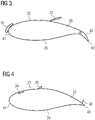
- the aerofoil shape of the aerofoil portion is symbolized by two aerofoil profiles which are respectively shown in Figures 3 and 4 and which illustrates the cross-sectional shape of the rotor blade at this spanwise position.
- the suction side 25 is divided or separated from the pressure side 26 by a leading edge 41, where the incoming airflow meets the blade 20 and a trailing edge 42, where the airflow leaves the blade.
- a first active aerodynamic device 31 is a slat provided at the leading edge 41
- a second active aerodynamic device 32 is a spoiler provided between the leading edge 41 and the trailing edge 42
- a third active aerodynamic device 33 is a flap provided at the trailing edge 42.
- a fourth active aerodynamic device 34 is a plurality of microjets for suction or blowing of air provided between the leading edge 41 and the trailing edge 42
- a fifth active aerodynamic device 35 is a plurality of vortex generators provided between the leading edge 41 and the trailing edge 42
- a sixth active aerodynamic device 36 is a plurality of micro tabs provided at the trailing edge 42.
- the active aerodynamic device 31, 32, 33, 34, 35, 36 are also shown on figure 2 : a flap 33 and a plurality of microjets 34 for suction or blowing of air being shown on a first rotor blade 20, a slat 31 and a flap 32 being shown on a second rotor blade 20, a plurality of vortex generators 35 and a plurality of micro tabs 36 being shown on a third rotor blade 20.
- the active aerodynamic devices 31, 32, 33, 34, 35, 36 provided on one rotor blade 20 may be different from the active aerodynamic devices 31, 32, 33, 34, 35, 36 provided on the other rotor blades 20.
- the blades 20 of the same wind turbine 10 may include the same active aerodynamic devices 31, 32, 33, 34, 35, 36.
- the blades 20 may include other type of active aerodynamic devices 31, 32, 33, 34, 35, 36, different from the ones above described.
- the aerodynamic device 31, 32, 33, 34, 35, 36 according to the present invention are movable between an inactive configuration, in which the influence of the aerodynamic device 31, 32, 33, 34, 35, 36 on the airflow is minimal or negligible and an active configuration in which the aerodynamic device 31, 32, 33, 34, 35, 36 influences the airflow.
- the spoiler 32 and the vortex generators 35 are aligned to the suction side 25 in the inactive configuration (not shown) and protruding from the suction side 25 in the active configuration (as shown in figures 3 and 4 , respectively).
- the flaps 33 and micro tabs 36 are aligned to the suction side 25 at the trailing edge 42 in the inactive configuration (not shown) and deviating from the the suction side 25 in the active configuration (as shown in figures 3 and 4 , respectively).
- the plurality of microjets 34 are open for suction or blowing of air in the active configuration and closed in the inactive configuration.
- Figure 2 further illustrates a plurality of sensors 201, 202, 203 installed on the wind turbine 10.
- a first sensor 201 may be on the nacelle 12, for example on the shaft connected to the wind rotor for measuring a bending motor on the shaft.
- a second sensor 202 may be provided on a rotor blade 20 at the root section 21.
- a third sensor 203 may be provided on a rotor blade 20 between the root section 21 and the tip section 22.
- the second sensor 202 and/or the third sensor 203 may be provide on any of the blades 20. According to other embodiments of the present invention (not shown), the sensor(s) may be provided in different number and positions.
- the wind turbine 10 further includes a controller 100 connected to the plurality of sensors 201, 202, 203 or receiving a respective sensor output signal.
- the sensor(s) 201, 202, 203 may be any sensor for generating as output signal a strain signal or displacement signal or rotation signal or natural frequency signal or rotational speed or acceleration signal.
- the controller 100 is further connected to a plurality of activators (not shown in figure 2 ) for respectively moving the aerodynamic device 31, 32, 33, 34, 35, 36 between their respective active and inactive configurations.
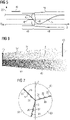
- Figure 5 schematically illustrates wind flow upstream and downstream a wind turbine having rotor blades rotating in a rotor disk 43, i.e. the disc swept by each complete rotation of each blade 20 about the rotor axis Y.
- the wind 19 Upstream the rotor disk 43, the wind 19 has a free-stream wind velocity U which then varies in dependence of a lateral position x according to a first curve 45 for a first turbulence and according to a second curve 46 for a second turbulence in a coordinate system having as ordinate 20 wind speed and having as abscissa lateral extent x.
- an axial induction zone 48 is defined.
- the axial induction zone 48 be described as the region where the inflow wind speed decelerates due to the extraction of kinetic energy from the free-stream wind flow.
- the rotor disk 43 including the rotating rotor blades exerts a force 47 on the wind 19 resulting in a decrease of the wind velocity 45 downstream the rotor disk 43.
- the wind velocity 45 reaches downstream the rotor disk 43 a minimum U min and increases then within a wake region 49 substantially towards the upstream wind velocity U.
- the region 51 defines a shape of the wake 49.
- the operating method according to the present invention comprises the steps of moving the aerodynamic device 31, 32, 33, 34, 35, 36 between an first configuration to a second configuration for influencing a wake generated by the wind turbine.
- the initial configuration of each aerodynamic device 31, 32, 33, 34, 35, 36 may be coincident with the respective inactive or active configuration.
- the final configuration of each aerodynamic device 31, 32, 33, 34, 35, 36 may be coincident with the respective active or inactive configuration.
- FIGS 6 and 7 schematically illustrates a first embodiment of the operating method.
- Each blade 20 includes three aerodynamic device 31, 32, 33, respectively radially internal (adjacent to the blade root 21), intermediate and radially external (adjacent to the blade tip 22).
- the rotor disc 43 is divided in two half rotor discs, the aerodynamic device 31, 32, 33 being moved to the respective active configuration only when they are in one of the two half rotor discs and in the respective inactive configuration only when they are in the other of the two half rotor discs.
- the wake region 49 is correspondently divided in a first sub-region 52 and in a second sub-region 53, the first sub-region 52 being more subject to the turbulences induced by the aerodynamic device 31, 32, 33 and therefore characterized by a faster recovery to ambient conditions.
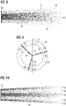
- Figures 8 and 9 schematically illustrates a second embodiment of the operating method.
- the second embodiment differentiates itself from the first embodiment in that only the external aerodynamic devices 33 are moved to the respective active configurations for at least a complete rotation of the wind rotor 13.
- the configuration of the aerodynamic devices 33 is therefore independent from the azimuth angle of the respective blade 20.
- the first sub-region 52 is therefore annularly shaped around the second sub-region 53 of the wake region 49.
- Figures 10 and 11 schematically illustrates a third embodiment of the operating method.
- the third embodiment differentiates itself from the second embodiment in that only the intermediate aerodynamic devices 32 are moved to the respective active configurations for at least a complete rotation of the wind rotor 13.
- the first sub-region 52 is therefore annularly shaped and interposed between an external portion of the second sub-region 53 and an internal portion of the second sub-region 53 of the wake region 49.
- Figures 12 and 13 schematically illustrates a fourth embodiment of the operating method.
- the fourth embodiment differentiates itself from the second embodiment in that only the internal aerodynamic devices 31 are moved to the respective active configurations for at least a complete rotation of the wind rotor 13.
- the first sub-region 52 is therefore conically shaped and surrounded by a second sub-region 53 of the wake region 49.
- the above described embodiments produce beneficial effects for a second downstream wind turbine 20 (as exemplary shown in figure 6 ) have a respective rotor disc 43 at least partially subject to the first sub-region 52 of the wake region 49 and not subject to the second sub-region 53 of the wake region 49.
- all the aerodynamic device 31, 32, 33 of one blade 20 are moved to the respective active configurations, independently from the azimuth angle of such blade 20.
- Activating the aerodynamic devices of the blades 20 individually generates yaw and tilt moments which may be measured and calculated in the controller 100 through the sensor(s) 201, 202, 203.
Landscapes
- Engineering & Computer Science (AREA)
- Life Sciences & Earth Sciences (AREA)
- Sustainable Development (AREA)
- Sustainable Energy (AREA)
- Chemical & Material Sciences (AREA)
- Combustion & Propulsion (AREA)
- Mechanical Engineering (AREA)
- General Engineering & Computer Science (AREA)
- Physics & Mathematics (AREA)
- Fluid Mechanics (AREA)
- Wind Motors (AREA)
Priority Applications (4)
| Application Number | Priority Date | Filing Date | Title |
|---|---|---|---|
| EP21172753.2A EP4086455A1 (fr) | 2021-05-07 | 2021-05-07 | Exploitation d'une éolienne pour le contrôle du sillage |
| PCT/EP2022/061799 WO2022233840A1 (fr) | 2021-05-07 | 2022-05-03 | Commande d'une éolienne pour le contrôle du sillage |
| US18/558,515 US20240240614A1 (en) | 2021-05-07 | 2022-05-03 | Operating a wind turbine for wake control |
| EP22727098.0A EP4305297A1 (fr) | 2021-05-07 | 2022-05-03 | Commande d'une éolienne pour le contrôle du sillage |
Applications Claiming Priority (1)
| Application Number | Priority Date | Filing Date | Title |
|---|---|---|---|
| EP21172753.2A EP4086455A1 (fr) | 2021-05-07 | 2021-05-07 | Exploitation d'une éolienne pour le contrôle du sillage |
Publications (1)
| Publication Number | Publication Date |
|---|---|
| EP4086455A1 true EP4086455A1 (fr) | 2022-11-09 |
Family
ID=75870476
Family Applications (2)
| Application Number | Title | Priority Date | Filing Date |
|---|---|---|---|
| EP21172753.2A Withdrawn EP4086455A1 (fr) | 2021-05-07 | 2021-05-07 | Exploitation d'une éolienne pour le contrôle du sillage |
| EP22727098.0A Pending EP4305297A1 (fr) | 2021-05-07 | 2022-05-03 | Commande d'une éolienne pour le contrôle du sillage |
Family Applications After (1)
| Application Number | Title | Priority Date | Filing Date |
|---|---|---|---|
| EP22727098.0A Pending EP4305297A1 (fr) | 2021-05-07 | 2022-05-03 | Commande d'une éolienne pour le contrôle du sillage |
Country Status (3)
| Country | Link |
|---|---|
| US (1) | US20240240614A1 (fr) |
| EP (2) | EP4086455A1 (fr) |
| WO (1) | WO2022233840A1 (fr) |
Cited By (1)
| Publication number | Priority date | Publication date | Assignee | Title |
|---|---|---|---|---|
| WO2023219517A1 (fr) * | 2022-05-13 | 2023-11-16 | Equinor Energy As | Commande de la diffusion d'un sillage généré par une éolienne |
Citations (2)
| Publication number | Priority date | Publication date | Assignee | Title |
|---|---|---|---|---|
| EP2757255A1 (fr) * | 2013-01-21 | 2014-07-23 | Alstom Wind, S.L.U. | Procédé de fonctionnement d'un parc éolien |
| EP3578808A1 (fr) * | 2018-06-08 | 2019-12-11 | Siemens Gamesa Renewable Energy A/S | Commande d'éoliennes en présence d'interactions de sillage |
Family Cites Families (6)
| Publication number | Priority date | Publication date | Assignee | Title |
|---|---|---|---|---|
| PT2007981T (pt) * | 2006-04-02 | 2021-02-11 | Wobben Properties Gmbh | Turbina eólica com pá esbelta |
| US8192161B2 (en) * | 2008-05-16 | 2012-06-05 | Frontier Wind, Llc. | Wind turbine with deployable air deflectors |
| US8167554B2 (en) * | 2011-01-28 | 2012-05-01 | General Electric Corporation | Actuatable surface features for wind turbine rotor blades |
| WO2012163362A2 (fr) * | 2011-06-03 | 2012-12-06 | Vestas Wind Systems A/S | Procédé de commande d'une éolienne |
| JP6869685B2 (ja) * | 2016-10-06 | 2021-05-12 | 株式会社日立製作所 | ウィンドファーム及び風力発電装置 |
| DE102018127804B4 (de) * | 2018-11-07 | 2024-07-25 | Vc Viii Polytech Holding Aps | Verbesserung bzw. Optimierung des Ertrags einer Windenergieanlage durch Detektion eines Strömungsabrisses |
-
2021
- 2021-05-07 EP EP21172753.2A patent/EP4086455A1/fr not_active Withdrawn
-
2022
- 2022-05-03 EP EP22727098.0A patent/EP4305297A1/fr active Pending
- 2022-05-03 US US18/558,515 patent/US20240240614A1/en active Pending
- 2022-05-03 WO PCT/EP2022/061799 patent/WO2022233840A1/fr active Application Filing
Patent Citations (2)
| Publication number | Priority date | Publication date | Assignee | Title |
|---|---|---|---|---|
| EP2757255A1 (fr) * | 2013-01-21 | 2014-07-23 | Alstom Wind, S.L.U. | Procédé de fonctionnement d'un parc éolien |
| EP3578808A1 (fr) * | 2018-06-08 | 2019-12-11 | Siemens Gamesa Renewable Energy A/S | Commande d'éoliennes en présence d'interactions de sillage |
Cited By (1)
| Publication number | Priority date | Publication date | Assignee | Title |
|---|---|---|---|---|
| WO2023219517A1 (fr) * | 2022-05-13 | 2023-11-16 | Equinor Energy As | Commande de la diffusion d'un sillage généré par une éolienne |
Also Published As
| Publication number | Publication date |
|---|---|
| EP4305297A1 (fr) | 2024-01-17 |
| US20240240614A1 (en) | 2024-07-18 |
| WO2022233840A1 (fr) | 2022-11-10 |
Similar Documents
| Publication | Publication Date | Title |
|---|---|---|
| US10934995B2 (en) | Blades and systems with forward blowing slots | |
| CA2608425C (fr) | Eoliennes a axe vertical | |
| EP2399825B1 (fr) | Ensemble de générateur de vortex à utiliser avec une pale de rotor d'éolienne | |
| EP2341245B1 (fr) | Appareil pour augmenter la portance d'une pale d'éolienne | |
| EP2425129B1 (fr) | Pale de rotor d'éolienne | |
| EP2034178B1 (fr) | Pale d'éolienne équipée de volets orientables | |
| EP2019203B2 (fr) | Pale d'éolienne avec des volets cambrés | |
| US20020153729A1 (en) | Controllable camber windmill blades | |
| US20120020803A1 (en) | Turbine blades, systems and methods | |
| EP2699796B1 (fr) | Turbines éoliennes amplifiées par un diffuseur | |
| JP2013217372A (ja) | 風車ロータブレード用の可撓性フラップ配列 | |
| US20150316025A1 (en) | Aerodynamic device for a rotor blade of a wind turbine | |
| EP3080402B1 (fr) | Déflecteur d'écoulement de pale | |
| US20240240614A1 (en) | Operating a wind turbine for wake control | |
| WO2023138823A1 (fr) | Système de commande destiné à maintenir la marge de décrochage d'une pale d'éolienne avec un dispositif aérodynamique actif | |
| US20170248114A1 (en) | A diffuser, user of a diffuser and a wind turbine comprising a diffuser | |
| AU2012244194A1 (en) | Vertical Axis Wind Turbines |
Legal Events
| Date | Code | Title | Description |
|---|---|---|---|
| PUAI | Public reference made under article 153(3) epc to a published international application that has entered the european phase |
Free format text: ORIGINAL CODE: 0009012 |
|
| STAA | Information on the status of an ep patent application or granted ep patent |
Free format text: STATUS: THE APPLICATION HAS BEEN PUBLISHED |
|
| AK | Designated contracting states |
Kind code of ref document: A1 Designated state(s): AL AT BE BG CH CY CZ DE DK EE ES FI FR GB GR HR HU IE IS IT LI LT LU LV MC MK MT NL NO PL PT RO RS SE SI SK SM TR |
|
| STAA | Information on the status of an ep patent application or granted ep patent |
Free format text: STATUS: THE APPLICATION IS DEEMED TO BE WITHDRAWN |
|
| 18D | Application deemed to be withdrawn |
Effective date: 20230510 |