EP4086433A1 - Ensemble joint d'étanchéité avec segment d'arc d'étanchéité - Google Patents
Ensemble joint d'étanchéité avec segment d'arc d'étanchéité Download PDFInfo
- Publication number
- EP4086433A1 EP4086433A1 EP22170289.7A EP22170289A EP4086433A1 EP 4086433 A1 EP4086433 A1 EP 4086433A1 EP 22170289 A EP22170289 A EP 22170289A EP 4086433 A1 EP4086433 A1 EP 4086433A1
- Authority
- EP
- European Patent Office
- Prior art keywords
- seal
- mate face
- gas turbine
- arc segment
- turbine engine
- Prior art date
- Legal status (The legal status is an assumption and is not a legal conclusion. Google has not performed a legal analysis and makes no representation as to the accuracy of the status listed.)
- Pending
Links
- 238000000429 assembly Methods 0.000 claims abstract description 22
- 230000000712 assembly Effects 0.000 claims abstract description 22
- 239000011153 ceramic matrix composite Substances 0.000 claims description 26
- 238000004891 communication Methods 0.000 claims description 5
- 239000000203 mixture Substances 0.000 claims description 5
- 239000012530 fluid Substances 0.000 claims description 4
- 239000000835 fiber Substances 0.000 description 7
- 238000007789 sealing Methods 0.000 description 6
- 229910010271 silicon carbide Inorganic materials 0.000 description 6
- HBMJWWWQQXIZIP-UHFFFAOYSA-N silicon carbide Chemical compound [Si+]#[C-] HBMJWWWQQXIZIP-UHFFFAOYSA-N 0.000 description 6
- 239000011248 coating agent Substances 0.000 description 5
- 238000000576 coating method Methods 0.000 description 5
- 239000000446 fuel Substances 0.000 description 5
- 239000011156 metal matrix composite Substances 0.000 description 5
- 229920002134 Carboxymethyl cellulose Polymers 0.000 description 4
- 235000010948 carboxy methyl cellulose Nutrition 0.000 description 4
- 229920006184 cellulose methylcellulose Polymers 0.000 description 4
- 238000012710 chemistry, manufacturing and control Methods 0.000 description 4
- 238000001816 cooling Methods 0.000 description 4
- 210000003746 feather Anatomy 0.000 description 4
- 239000000463 material Substances 0.000 description 4
- 239000011159 matrix material Substances 0.000 description 4
- 229910052751 metal Inorganic materials 0.000 description 3
- 239000002184 metal Substances 0.000 description 3
- 230000009467 reduction Effects 0.000 description 3
- 229910000990 Ni alloy Inorganic materials 0.000 description 2
- PXHVJJICTQNCMI-UHFFFAOYSA-N Nickel Chemical compound [Ni] PXHVJJICTQNCMI-UHFFFAOYSA-N 0.000 description 2
- VYPSYNLAJGMNEJ-UHFFFAOYSA-N Silicium dioxide Chemical compound O=[Si]=O VYPSYNLAJGMNEJ-UHFFFAOYSA-N 0.000 description 2
- MCMNRKCIXSYSNV-UHFFFAOYSA-N Zirconium dioxide Chemical compound O=[Zr]=O MCMNRKCIXSYSNV-UHFFFAOYSA-N 0.000 description 2
- 230000008901 benefit Effects 0.000 description 2
- 239000000919 ceramic Substances 0.000 description 2
- 238000002955 isolation Methods 0.000 description 2
- 238000010926 purge Methods 0.000 description 2
- 230000003068 static effect Effects 0.000 description 2
- 229910000601 superalloy Inorganic materials 0.000 description 2
- 239000012720 thermal barrier coating Substances 0.000 description 2
- 229910052580 B4C Inorganic materials 0.000 description 1
- 229910000531 Co alloy Inorganic materials 0.000 description 1
- 241000588731 Hafnia Species 0.000 description 1
- BPQQTUXANYXVAA-UHFFFAOYSA-N Orthosilicate Chemical compound [O-][Si]([O-])([O-])[O-] BPQQTUXANYXVAA-UHFFFAOYSA-N 0.000 description 1
- XUIMIQQOPSSXEZ-UHFFFAOYSA-N Silicon Chemical compound [Si] XUIMIQQOPSSXEZ-UHFFFAOYSA-N 0.000 description 1
- 229910052782 aluminium Inorganic materials 0.000 description 1
- XAGFODPZIPBFFR-UHFFFAOYSA-N aluminium Chemical compound [Al] XAGFODPZIPBFFR-UHFFFAOYSA-N 0.000 description 1
- PNEYBMLMFCGWSK-UHFFFAOYSA-N aluminium oxide Inorganic materials [O-2].[O-2].[O-2].[Al+3].[Al+3] PNEYBMLMFCGWSK-UHFFFAOYSA-N 0.000 description 1
- 230000004323 axial length Effects 0.000 description 1
- INAHAJYZKVIDIZ-UHFFFAOYSA-N boron carbide Chemical compound B12B3B4C32B41 INAHAJYZKVIDIZ-UHFFFAOYSA-N 0.000 description 1
- 229910010293 ceramic material Inorganic materials 0.000 description 1
- 230000008859 change Effects 0.000 description 1
- 229910017052 cobalt Inorganic materials 0.000 description 1
- 239000010941 cobalt Substances 0.000 description 1
- GUTLYIVDDKVIGB-UHFFFAOYSA-N cobalt atom Chemical compound [Co] GUTLYIVDDKVIGB-UHFFFAOYSA-N 0.000 description 1
- 238000002485 combustion reaction Methods 0.000 description 1
- 230000000295 complement effect Effects 0.000 description 1
- 230000006835 compression Effects 0.000 description 1
- 238000007906 compression Methods 0.000 description 1
- 239000013078 crystal Substances 0.000 description 1
- CJNBYAVZURUTKZ-UHFFFAOYSA-N hafnium(IV) oxide Inorganic materials O=[Hf]=O CJNBYAVZURUTKZ-UHFFFAOYSA-N 0.000 description 1
- 238000001764 infiltration Methods 0.000 description 1
- 230000008595 infiltration Effects 0.000 description 1
- 230000007246 mechanism Effects 0.000 description 1
- 229910001092 metal group alloy Inorganic materials 0.000 description 1
- 150000002739 metals Chemical class 0.000 description 1
- 238000012986 modification Methods 0.000 description 1
- 230000004048 modification Effects 0.000 description 1
- 229910052759 nickel Inorganic materials 0.000 description 1
- 230000004044 response Effects 0.000 description 1
- 229910052710 silicon Inorganic materials 0.000 description 1
- 239000010703 silicon Substances 0.000 description 1
- 239000000377 silicon dioxide Substances 0.000 description 1
- 229910001233 yttria-stabilized zirconia Inorganic materials 0.000 description 1
Images


Classifications
-
- F—MECHANICAL ENGINEERING; LIGHTING; HEATING; WEAPONS; BLASTING
- F01—MACHINES OR ENGINES IN GENERAL; ENGINE PLANTS IN GENERAL; STEAM ENGINES
- F01D—NON-POSITIVE DISPLACEMENT MACHINES OR ENGINES, e.g. STEAM TURBINES
- F01D11/00—Preventing or minimising internal leakage of working-fluid, e.g. between stages
- F01D11/08—Preventing or minimising internal leakage of working-fluid, e.g. between stages for sealing space between rotor blade tips and stator
-
- F—MECHANICAL ENGINEERING; LIGHTING; HEATING; WEAPONS; BLASTING
- F01—MACHINES OR ENGINES IN GENERAL; ENGINE PLANTS IN GENERAL; STEAM ENGINES
- F01D—NON-POSITIVE DISPLACEMENT MACHINES OR ENGINES, e.g. STEAM TURBINES
- F01D9/00—Stators
- F01D9/06—Fluid supply conduits to nozzles or the like
- F01D9/065—Fluid supply or removal conduits traversing the working fluid flow, e.g. for lubrication-, cooling-, or sealing fluids
-
- F—MECHANICAL ENGINEERING; LIGHTING; HEATING; WEAPONS; BLASTING
- F01—MACHINES OR ENGINES IN GENERAL; ENGINE PLANTS IN GENERAL; STEAM ENGINES
- F01D—NON-POSITIVE DISPLACEMENT MACHINES OR ENGINES, e.g. STEAM TURBINES
- F01D11/00—Preventing or minimising internal leakage of working-fluid, e.g. between stages
- F01D11/001—Preventing or minimising internal leakage of working-fluid, e.g. between stages for sealing space between stator blade and rotor
-
- F—MECHANICAL ENGINEERING; LIGHTING; HEATING; WEAPONS; BLASTING
- F01—MACHINES OR ENGINES IN GENERAL; ENGINE PLANTS IN GENERAL; STEAM ENGINES
- F01D—NON-POSITIVE DISPLACEMENT MACHINES OR ENGINES, e.g. STEAM TURBINES
- F01D11/00—Preventing or minimising internal leakage of working-fluid, e.g. between stages
- F01D11/003—Preventing or minimising internal leakage of working-fluid, e.g. between stages by packing rings; Mechanical seals
-
- F—MECHANICAL ENGINEERING; LIGHTING; HEATING; WEAPONS; BLASTING
- F01—MACHINES OR ENGINES IN GENERAL; ENGINE PLANTS IN GENERAL; STEAM ENGINES
- F01D—NON-POSITIVE DISPLACEMENT MACHINES OR ENGINES, e.g. STEAM TURBINES
- F01D11/00—Preventing or minimising internal leakage of working-fluid, e.g. between stages
- F01D11/005—Sealing means between non relatively rotating elements
-
- F—MECHANICAL ENGINEERING; LIGHTING; HEATING; WEAPONS; BLASTING
- F01—MACHINES OR ENGINES IN GENERAL; ENGINE PLANTS IN GENERAL; STEAM ENGINES
- F01D—NON-POSITIVE DISPLACEMENT MACHINES OR ENGINES, e.g. STEAM TURBINES
- F01D25/00—Component parts, details, or accessories, not provided for in, or of interest apart from, other groups
- F01D25/08—Cooling; Heating; Heat-insulation
- F01D25/12—Cooling
-
- F—MECHANICAL ENGINEERING; LIGHTING; HEATING; WEAPONS; BLASTING
- F01—MACHINES OR ENGINES IN GENERAL; ENGINE PLANTS IN GENERAL; STEAM ENGINES
- F01D—NON-POSITIVE DISPLACEMENT MACHINES OR ENGINES, e.g. STEAM TURBINES
- F01D9/00—Stators
- F01D9/02—Nozzles; Nozzle boxes; Stator blades; Guide conduits, e.g. individual nozzles
- F01D9/04—Nozzles; Nozzle boxes; Stator blades; Guide conduits, e.g. individual nozzles forming ring or sector
- F01D9/042—Nozzles; Nozzle boxes; Stator blades; Guide conduits, e.g. individual nozzles forming ring or sector fixing blades to stators
-
- F—MECHANICAL ENGINEERING; LIGHTING; HEATING; WEAPONS; BLASTING
- F02—COMBUSTION ENGINES; HOT-GAS OR COMBUSTION-PRODUCT ENGINE PLANTS
- F02C—GAS-TURBINE PLANTS; AIR INTAKES FOR JET-PROPULSION PLANTS; CONTROLLING FUEL SUPPLY IN AIR-BREATHING JET-PROPULSION PLANTS
- F02C7/00—Features, components parts, details or accessories, not provided for in, or of interest apart form groups F02C1/00 - F02C6/00; Air intakes for jet-propulsion plants
- F02C7/28—Arrangement of seals
-
- F—MECHANICAL ENGINEERING; LIGHTING; HEATING; WEAPONS; BLASTING
- F05—INDEXING SCHEMES RELATING TO ENGINES OR PUMPS IN VARIOUS SUBCLASSES OF CLASSES F01-F04
- F05D—INDEXING SCHEME FOR ASPECTS RELATING TO NON-POSITIVE-DISPLACEMENT MACHINES OR ENGINES, GAS-TURBINES OR JET-PROPULSION PLANTS
- F05D2220/00—Application
- F05D2220/30—Application in turbines
- F05D2220/32—Application in turbines in gas turbines
- F05D2220/323—Application in turbines in gas turbines for aircraft propulsion, e.g. jet engines
-
- F—MECHANICAL ENGINEERING; LIGHTING; HEATING; WEAPONS; BLASTING
- F05—INDEXING SCHEMES RELATING TO ENGINES OR PUMPS IN VARIOUS SUBCLASSES OF CLASSES F01-F04
- F05D—INDEXING SCHEME FOR ASPECTS RELATING TO NON-POSITIVE-DISPLACEMENT MACHINES OR ENGINES, GAS-TURBINES OR JET-PROPULSION PLANTS
- F05D2240/00—Components
- F05D2240/10—Stators
- F05D2240/11—Shroud seal segments
-
- F—MECHANICAL ENGINEERING; LIGHTING; HEATING; WEAPONS; BLASTING
- F05—INDEXING SCHEMES RELATING TO ENGINES OR PUMPS IN VARIOUS SUBCLASSES OF CLASSES F01-F04
- F05D—INDEXING SCHEME FOR ASPECTS RELATING TO NON-POSITIVE-DISPLACEMENT MACHINES OR ENGINES, GAS-TURBINES OR JET-PROPULSION PLANTS
- F05D2240/00—Components
- F05D2240/55—Seals
- F05D2240/56—Brush seals
-
- F—MECHANICAL ENGINEERING; LIGHTING; HEATING; WEAPONS; BLASTING
- F05—INDEXING SCHEMES RELATING TO ENGINES OR PUMPS IN VARIOUS SUBCLASSES OF CLASSES F01-F04
- F05D—INDEXING SCHEME FOR ASPECTS RELATING TO NON-POSITIVE-DISPLACEMENT MACHINES OR ENGINES, GAS-TURBINES OR JET-PROPULSION PLANTS
- F05D2240/00—Components
- F05D2240/80—Platforms for stationary or moving blades
- F05D2240/81—Cooled platforms
-
- F—MECHANICAL ENGINEERING; LIGHTING; HEATING; WEAPONS; BLASTING
- F05—INDEXING SCHEMES RELATING TO ENGINES OR PUMPS IN VARIOUS SUBCLASSES OF CLASSES F01-F04
- F05D—INDEXING SCHEME FOR ASPECTS RELATING TO NON-POSITIVE-DISPLACEMENT MACHINES OR ENGINES, GAS-TURBINES OR JET-PROPULSION PLANTS
- F05D2260/00—Function
- F05D2260/20—Heat transfer, e.g. cooling
- F05D2260/201—Heat transfer, e.g. cooling by impingement of a fluid
-
- F—MECHANICAL ENGINEERING; LIGHTING; HEATING; WEAPONS; BLASTING
- F05—INDEXING SCHEMES RELATING TO ENGINES OR PUMPS IN VARIOUS SUBCLASSES OF CLASSES F01-F04
- F05D—INDEXING SCHEME FOR ASPECTS RELATING TO NON-POSITIVE-DISPLACEMENT MACHINES OR ENGINES, GAS-TURBINES OR JET-PROPULSION PLANTS
- F05D2300/00—Materials; Properties thereof
- F05D2300/60—Properties or characteristics given to material by treatment or manufacturing
- F05D2300/603—Composites; e.g. fibre-reinforced
- F05D2300/6033—Ceramic matrix composites [CMC]
-
- Y—GENERAL TAGGING OF NEW TECHNOLOGICAL DEVELOPMENTS; GENERAL TAGGING OF CROSS-SECTIONAL TECHNOLOGIES SPANNING OVER SEVERAL SECTIONS OF THE IPC; TECHNICAL SUBJECTS COVERED BY FORMER USPC CROSS-REFERENCE ART COLLECTIONS [XRACs] AND DIGESTS
- Y02—TECHNOLOGIES OR APPLICATIONS FOR MITIGATION OR ADAPTATION AGAINST CLIMATE CHANGE
- Y02T—CLIMATE CHANGE MITIGATION TECHNOLOGIES RELATED TO TRANSPORTATION
- Y02T50/00—Aeronautics or air transport
- Y02T50/60—Efficient propulsion technologies, e.g. for aircraft
Definitions
- a gas turbine engine typically includes a fan section, a compressor section, a combustor section and a turbine section. Air entering the compressor section is compressed and delivered into the combustion section where it is mixed with fuel and ignited to generate a high-pressure and temperature gas flow. The high-pressure and temperature gas flow expands through the turbine section to drive the compressor and the fan section.
- the compressor section may include low and high pressure compressors, and the turbine section may also include low and high pressure turbines.
- Airfoils in the turbine section are typically formed of a superalloy and may include thermal barrier coatings to extend temperature capability and lifetime. Ceramic matrix composite (“CMC”) materials are also being considered for airfoils. Among other attractive properties, CMCs have high temperature resistance. Despite this attribute, however, there are unique challenges to implementing CMCs in airfoils.
- a seal assembly that includes first, second, and third gas turbine engine components that are successively arranged around an axis.
- Each of the first, second, and third gas turbine engine components has first and second mate faces such that the first mate face of the first gas turbine engine component is adjacent to the second mate face of the second gas turbine engine component to define a first mate face gap there between and the first mate face of the second gas turbine engine component is adjacent to the second mate face of the third gas turbine engine component to define a second mate face gap there between.
- a seal arc segment is arranged around the axis.
- the seal arc segment has first and second seal portions that are circumferentially spaced-apart and a connector portion joining the first and second seal portions.
- the seal arc segment is arranged such that the first seal portion bridges the first mate face gap to seal the first mate face gap.
- the second seal portion bridges the second mate face gap to seal the second mate face gap, and the connector portion spans circumferentially across the second gas turbine engine component.
- the connector portion includes at least one opening (or a single opening).
- the second gas turbine engine component includes a collar that extends through the single opening.
- first and second mate face gaps each define a mate face gap length, and each of the first and second seal portions extend along a majority of the mate face gap length.
- first and second seal portions extend over a middle section of the mate face gap length and opposed end sections of the mate face gap length extend forward of and aft of the first and second seal portions.
- the seal arc segment is formed of ceramic matrix composite.
- the seal arc segment includes at least one impingement hole.
- a further embodiment of any of the foregoing includes at least one brush seal that seals against a radially outer surface of the seal arc segment.
- first, second, and third gas turbine engine components are vane assemblies.
- each of the vane assemblies includes a ceramic matrix composite airfoil fairing that has inner and outer platforms and an airfoil section that extends there between.
- the outer platform has forward and aft flanges, and the seal arc segment extends between the forward and aft flanges of each of the vane assemblies.
- the seal arc segment is formed of a ceramic matrix composite.
- the ceramic matrix composite and the ceramic matrix composite airfoil fairing have equivalent compositions.
- a gas turbine engine which the Applicant expressly reserves the right to claim independently, that includes a compressor section, a combustor in fluid communication with the compressor section, and a turbine section in fluid communication with the combustor.
- the turbine section has first, second, and third vane assemblies that are successively arranged around an axis.
- Each of the first, second, and third vane assemblies has first and second mate faces such that the first mate face of the first vane assembly is adjacent to the second mate face of the second vane assembly to define a first mate face gap there between and the first mate face of the second vane assembly is adjacent to the second mate face of the third vane assembly to define a second mate face gap there between.
- a seal arc segment arranged around the axis.
- the seal arc segment has first and second seal portions that are circumferentially spaced-apart and a connector portion joining the first and second seal portions.
- the seal arc segment is arranged such that the first seal portion bridges the first mate face gap to seal the first mate face gap.
- the second seal portion bridges the second mate face gap to seal the second mate face gap, and the connector portion spans circumferentially across the second gas turbine engine component.
- An embodiment of the foregoing includes a brush seal that seals against a radially outer surface of the seal arc segment.
- each of the first, second, and third vane assemblies includes a ceramic matrix composite airfoil fairing that has inner and outer platforms and an airfoil section that extends there between.
- the outer platform has forward and aft flanges, and the seal arc segment extends between the forward and aft flanges of each of the first, second, and third vane assemblies.
- first and second mate face gaps each define a mate face gap length, and each of the first and second seal portions extend along a majority of the mate face gap length.
- first and second seal portions extend over a middle section of the mate face gap length and opposed end sections of the mate face gap length extend forward of and aft of the first and second seal portions.
- the seal arc segment is formed of ceramic matrix composite.
- the connector portion includes a single opening and the second vane assembly includes a collar that extends through the single opening.
- the seal arc segment includes at least one impingement hole.
- the present disclosure may include any one or more of the individual features disclosed above and/or below alone or in any combination thereof.
- FIG. 1 schematically illustrates a gas turbine engine 20.
- the gas turbine engine 20 is disclosed herein as a two-spool turbofan that generally incorporates a fan section 22, a compressor section 24, a combustor section 26 and a turbine section 28.
- the fan section 22 drives air along a bypass flow path B in a bypass duct defined within a housing 15 such as a fan case or nacelle, and also drives air along a core flow path C for compression and communication into the combustor section 26 then expansion through the turbine section 28.
- the exemplary engine 20 generally includes a low speed spool 30 and a high speed spool 32 mounted for rotation about an engine central longitudinal axis A relative to an engine static structure 36 via several bearing systems 38. It should be understood that various bearing systems 38 at various locations may alternatively or additionally be provided, and the location of bearing systems 38 may be varied as appropriate to the application.
- the low speed spool 30 generally includes an inner shaft 40 that interconnects, a first (or low) pressure compressor 44 and a first (or low) pressure turbine 46.
- the inner shaft 40 is connected to the fan 42 through a speed change mechanism, which in exemplary gas turbine engine 20 is illustrated as a geared architecture 48 to drive a fan 42 at a lower speed than the low speed spool 30.
- the high speed spool 32 includes an outer shaft 50 that interconnects a second (or high) pressure compressor 52 and a second (or high) pressure turbine 54.
- a combustor 56 is arranged in the exemplary gas turbine 20 between the high pressure compressor 52 and the high pressure turbine 54.
- a mid-turbine frame 57 of the engine static structure 36 may be arranged generally between the high pressure turbine 54 and the low pressure turbine 46.
- the mid-turbine frame 57 further supports bearing systems 38 in the turbine section 28.
- the inner shaft 40 and the outer shaft 50 are concentric and rotate via bearing systems 38 about the engine central longitudinal axis A which is collinear with their longitudinal axes.
- the core airflow is compressed by the low pressure compressor 44 then the high pressure compressor 52, mixed and burned with fuel in the combustor 56, then expanded through the high pressure turbine 54 and low pressure turbine 46.
- the mid-turbine frame 57 includes airfoils 59 which are in the core airflow path C.
- the turbines 46, 54 rotationally drive the respective low speed spool 30 and high speed spool 32 in response to the expansion.
- gear system 48 may be located aft of the low pressure compressor, or aft of the combustor section 26 or even aft of turbine section 28, and fan 42 may be positioned forward or aft of the location of gear system 48.
- the engine 20 in one example is a high-bypass geared aircraft engine.
- the engine 20 bypass ratio is greater than about six (6), with an example embodiment being greater than about ten (10), and can be less than or equal to about 18.0, or more narrowly can be less than or equal to 16.0.
- the geared architecture 48 is an epicyclic gear train, such as a planetary gear system or other gear system, with a gear reduction ratio of greater than about 2.3.
- the gear reduction ratio may be less than or equal to 4.0.
- the low pressure turbine 46 has a pressure ratio that is greater than about five.
- the low pressure turbine pressure ratio can be less than or equal to 13.0, or more narrowly less than or equal to 12.0.
- the engine 20 bypass ratio is greater than about ten (10:1)
- the fan diameter is significantly larger than that of the low pressure compressor 44
- the low pressure turbine 46 has a pressure ratio that is greater than about five 5:1.
- Low pressure turbine 46 pressure ratio is pressure measured prior to an inlet of low pressure turbine 46 as related to the pressure at the outlet of the low pressure turbine 46 prior to an exhaust nozzle.
- the geared architecture 48 may be an epicycle gear train, such as a planetary gear system or other gear system, with a gear reduction ratio of greater than about 2.3:1 and less than about 5:1. It should be understood, however, that the above parameters are only exemplary of one embodiment of a geared architecture engine and that the present invention is applicable to other gas turbine engines including direct drive turbofans.
- the fan section 22 of the engine 20 is designed for a particular flight condition -- typically cruise at about 0.8 Mach and about 35,000 feet (10,668 meters).
- the flight condition of 0.8 Mach and 35,000 ft (10,668 meters), with the engine at its best fuel consumption - also known as "bucket cruise Thrust Specific Fuel Consumption ('TSFC')" - is the industry standard parameter of lbm of fuel being burned divided by lbf of thrust the engine produces at that minimum point.
- 'TSFC' Thrust Specific Fuel Consumption
- “Low fan pressure ratio” is the pressure ratio across the fan blade alone, without a Fan Exit Guide Vane (“FEGV”) system.
- the low fan pressure ratio as disclosed herein according to one non-limiting embodiment is less than about 1.45, or more narrowly greater than or equal to 1.25.
- the "Low corrected fan tip speed" as disclosed herein according to one non-limiting embodiment is less than about 1150.0 ft / second (350.5 meters/second), and can be greater than or equal to 1000.0 ft / second (304.8 meters/second).
- Figure 2 illustrates an example implementation of a seal assembly 60 in the turbine section 28 of the engine 20 (see also Figure 1 ).
- the seal assembly 60 is employed with a plurality of gas turbine engine components 62 (one shown in Figure 2 ) that are arranged circumferentially around the central engine axis A.
- the gas turbine engine components 62 are vane assemblies, but it is to be understood that the seal assembly 60 may be employed with other components that border the core gas path of the engine 20 and have mate face gaps, such as outer air seals.
- the vane assemblies 62 each include an airfoil fairing 63 that is comprised of an airfoil section 64 and first and second platforms 66/68 between which the airfoil section 64 extends.
- the platform 66 includes a base wall 66a, forward and aft flanges 66b/66c that protrude radially from the base wall 66a, and mate faces 66d.
- the mate faces 66d are the circumferential sides of the platform 66 and may include a slot 67 for receiving a feather seal (not shown).
- Brush seals 69 are provided at the forward and trailing ends of the platform 66 to facilitate isolating a plenum region bounded by the base wall 66a and the flanges 66b/66c.
- the platform 66 also includes a collar 66e that protrudes radially from the base wall 66a.
- the platform 68 may also have one or more flanges, which may serve to transfer aerodynamic loads from the airfoil fairing 63.
- platform 66 may have protruding flanges instead or, or in addition to, the collar.
- the first platform 66 is an outer platform and the second platform 68 is an inner platform.
- the terms such as “inner” and “outer” used herein refer to location with respect to the central engine axis A, i.e., radially inner or radially outer.
- first and second used herein is to differentiate that there are two architecturally distinct components or features. It is to be further understood that the terms “first” and “second” are interchangeable in that a first component or feature could alternatively be termed as the second component or feature, and vice versa.
- the airfoil section 64 generally extends in a radial direction relative to the central engine axis A and defines leading and trailing edges 64a/64b, a suction side 64c, and a pressure side 64d.
- the airfoil section 64 is hollow and circumscribes an interior through-cavity 70.
- the airfoil section 64 may have a single through-cavity 70, or the cavity 70 may be sub-divided by one or more ribs.
- the airfoil fairing includes one rib 70a that sub-divides the cavity 70 into forward and aft sub-cavities.
- the aforementioned collar 66e is an extension of a tube that forms the rib 70a and the forward sub-cavity in the airfoil section 64.
- the airfoil fairing 63 is a continuous, one-piece body.
- the airfoil fairing 63 is formed of a ceramic material or a metal matrix composite (MMC).
- the material is a ceramic matrix composite, or a metal matrix composite (MMC).
- the ceramic matrix composite (CMC) is formed of ceramic fiber tows that are disposed in a ceramic matrix.
- the ceramic matrix composite may be, but is not limited to, a SiC/SiC ceramic matrix composite in which SiC fiber tows are disposed within a SiC matrix.
- Example metal matrix composites include, but are not limited to, boron carbide fiber tows and/or alumina fiber tows disposed in a metal matrix, such as aluminum.
- the fiber tows are arranged in a fiber architecture, which refers to an ordered arrangement of the tows relative to one another, such as a 2D woven ply (e.g. a braid) or a 3D structure.
- the vane assembly 62 further includes a spar 72 that extends through the through-cavity 70 (e.g., the forward sub-cavity) and mechanically supports the airfoil fairing 63.
- the spar 72 may be formed of a relatively high temperature resistance, high strength material, such as a nickel or cobalt based superalloy (e.g. a single crystal nickel alloy).
- the spar 72 includes a spar flange 72a and a spar leg 72b that extends from the spar flange 72a, through the collar 66e of the platform 66, and into the through-cavity 70 (e.g., the forward sub-cavity).
- the spar leg 72b defines an interior through-passage 72c, and the spar flange 72a is supported at an outer end to support hardware S.
- the spar leg 72b has an inner end portion that has an attachment 74, such as but not limited to, a pin.
- the inner end of the spar leg 72b extends past the platform 68 of the airfoil fairing 63 so as to protrude from the fairing 63.
- the inner end is attached (e.g., by the pin) to additional support hardware S adjacent the platform 68 of the airfoil fairing 63.
- the airfoil fairing 63 is thus trapped between the inner support hardware S and the spar flange 72a and outer support hardware S.
- Airflow such as bleed air from the compressor section 24, is provided in and around the vane assembly to meet various objectives.
- zone Z1 air is used to purge the region around the forward flange 66b and brush seal 69.
- zone Z2 air is used to cool the region of the leading edge 64a of the airfoil section 64; and in zone Z3 air may be used to purge the region around aft flange 66c.
- zone Z3 is at the lowest pressure, air from the zones Z1 and Z2 tends to leak to zone Z3.
- the seal assembly 60 facilitates isolation of the zones Z1/Z2/Z3.
- the seal assembly 60 is implemented at the outer platforms 66 of the airfoil fairings 63 and includes a seal arc segment 76.
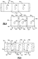
- Figure 3 illustrates an isolated view of the seal arc segment 76.
- the seal arc segment 76 is a sector of a circular ring.
- the seal arc segment 76 spans across at least three or more vane assemblies 62.
- multiple seal arc segments 76 would make a full ring, such as bi-segment halves, tri-segment thirds, or quad-segment quarters in a ring.
- Each seal arc segment 76 includes seal portions 76a that are circumferentially spaced-apart and a connector portions 76b that join the seal portions 76a such that there are alternating seal portions 76a and connector portions 76b.
- each of the connector portions 76b includes an opening 76c to receive the collar 66e there through.
- the opening 76c is completely bound within the connector portion 76b, and the shape of the opening 76c is a complement of the shape of the collar 66e such that the collar 66e fits closely through the opening 76c.
- the seal arc segment 76 may be formed of a metal alloy, such as a nickel- or cobalt-based alloy, or a ceramic matrix composite.
- the airfoil fairing 63 and the seal arc segment 76 are both formed of CMCs.
- the CMCs of the airfoil fairing 63 and the seal arc segment 76 are of equivalent compositions.
- the equivalent compositions have the same kind of fibers (e.g., silicon carbide) and the same kind of matrix (e.g., silicon carbide) however the layup architecture (weave, braid, uni-tape, etc.) may be different.
- the vane assemblies 62 are circumferentially successively arranged such that the (first) mate face 66d of the first one of the vane assemblies (the left-most) is adjacent the (second) mate face 66d of the second one of the vane assemblies (the middle) to define a (first) mate face gap 78 there between.
- the (first) mate face 66d of the second (middle) one of the vane assemblies 62 is adjacent the (second) mate face 66d of the third one of the vane assemblies (rightmost) to define a (second) mate face gap 78 there between.
- the seal arc segment 76 is received onto the platforms 66 of the three circumferentially successive vane assemblies 62.
- the collars 66e fit into the openings 76c in the connector portions 76b of the seal arc segments 76, which may also serve as pilots for proper location of the seal arc segment 76.
- the seal arc segment 76 is situated on the base walls 66a of the platforms 66 (see also Figure 2 ) axially between the flanges 66b/66c such that the connector portions 76b span circumferentially across the base walls 66a.
- the seal portions 76a contact the base walls 66a of the adjacent platforms 66 and bridge across the mate face gaps 78 to seal the mate face gaps 78.
- the brush seals 69 ( Figure 2 ) contact the outer surface of the seal arc segment 76 to seal therewith.
- the seal portions 76a that bridge over the mate face gaps 78 provide additional sealing against infiltration of hot gas from the core gas path and/or the escape of cooling air from zone Z2. This additional sealing, together with the sealing provided by the brush seals 69, thereby facilitates the isolation of zone Z2 from zones Z1 and Z3.
- the seal arc segment 76 may also serve as a thermal shield to protect the brush seals 69 from high temperatures that may be experienced in the platform 66.
- forming the seal arc segment 76 from a relatively low thermal conductivity material (in comparison to metals), such as the CMC discussed above facilitates enhancement of thermal shielding.
- a metal arc seal segment may be coated with a thermal barrier coating such as yttria stabilized zirconia.
- the mate face gaps 78 each define a mate face gap length G, which is equal to the axial length of the platforms 66.
- the seal portions 76a extend only along a majority of the mate face gap length G rather than the full extent of the mate face gap length G.
- the seal portions 76a extend over the middle section of the mate face gap length G and opposed end sections of the mate face gap length G extend forward of and aft of the seal portions 76a.
- the seal portions 76a do not seal the entire mate face gap 78, and the end sections of the mate face gap length G rely on only the sealing provided by the feather seals.
- the seal portions 76a may include one or more impingement holes 76d. Cooling air that is provided into zone Z2 (see Figure 2 ) is discharged through the impingement holes 76d into the mate face gaps 78.
- the size and number of impingement holes 76d may be selected to meter the amount of cooling air provided, to cool the feather seal and/or cool the mate faces 66d.
- the impingement holes 76d may also be placed in other regions of the seal portion 76b to cool specific areas of the platform 66.
- the perimeter surface regions of the fairing platforms 66 that are in contact with the seal portions 76a may include a coating, for thermal considerations, to smooth the surface for better sealing contact, and/or reduce wear.
- the coating is selected of a composition that is thermally insulating in comparison to the CMC (if used) of the airfoil fairings 63, to thermally insulate the seal arc segment 76.
- the coating may be composed of elemental silicon, silicate, silica, hafnia, zirconia, or combinations thereof.
- the coating may be only on the perimeter portions of the platforms, including along the mate face edges 66d, there may be a cavity 80 defined between the seal arc segment 76, the radial surface of the platform 66, and the coating.
- One or more impingement holes 76d may be provided in the connector portions 76b that open to the cavity 80 to provide cooling to the surface of the platform 66 and thereby facilitate control over the temperature of regions in contact with the brush seals 69.
Landscapes
- Engineering & Computer Science (AREA)
- Mechanical Engineering (AREA)
- General Engineering & Computer Science (AREA)
- Chemical & Material Sciences (AREA)
- Combustion & Propulsion (AREA)
- Physics & Mathematics (AREA)
- Fluid Mechanics (AREA)
- Turbine Rotor Nozzle Sealing (AREA)
Applications Claiming Priority (1)
| Application Number | Priority Date | Filing Date | Title |
|---|---|---|---|
| US17/307,139 US11674404B2 (en) | 2021-05-04 | 2021-05-04 | Seal assembly with seal arc segment |
Publications (1)
| Publication Number | Publication Date |
|---|---|
| EP4086433A1 true EP4086433A1 (fr) | 2022-11-09 |
Family
ID=81388836
Family Applications (1)
| Application Number | Title | Priority Date | Filing Date |
|---|---|---|---|
| EP22170289.7A Pending EP4086433A1 (fr) | 2021-05-04 | 2022-04-27 | Ensemble joint d'étanchéité avec segment d'arc d'étanchéité |
Country Status (2)
| Country | Link |
|---|---|
| US (1) | US11674404B2 (fr) |
| EP (1) | EP4086433A1 (fr) |
Cited By (1)
| Publication number | Priority date | Publication date | Assignee | Title |
|---|---|---|---|---|
| US11879340B1 (en) | 2022-09-30 | 2024-01-23 | Rtx Corporation | Angled brush seal and gas turbine engine component combination |
Citations (7)
| Publication number | Priority date | Publication date | Assignee | Title |
|---|---|---|---|---|
| US2221684A (en) * | 1938-08-27 | 1940-11-12 | Gen Electric | Elastic fluid turbine bucket wheel |
| GB2235253A (en) * | 1989-08-16 | 1991-02-27 | Rolls Royce Plc | Ceramic guide vane for gas turbine engine |
| EP2172620A1 (fr) * | 2007-06-22 | 2010-04-07 | Mitsubishi Heavy Industries, Ltd. | Aubage de stator et compresseur à écoulement axial l'utilisant |
| WO2014100347A1 (fr) * | 2012-12-21 | 2014-06-26 | United Technologies Corporation | Fabrication d'ensemble aube à entretoise de couronne complète |
| US20140271105A1 (en) * | 2013-03-13 | 2014-09-18 | Pratt & Whitney Canada Corp. | Turbine shroud segment sealing |
| EP3088684A1 (fr) * | 2015-04-27 | 2016-11-02 | United Technologies Corporation | Amortisseur de stator et procédé correspondant de fabrication |
| EP3557001A1 (fr) * | 2018-04-18 | 2019-10-23 | United Technologies Corporation | Agencement de refroidissement pour composants de moteur |
Family Cites Families (6)
| Publication number | Priority date | Publication date | Assignee | Title |
|---|---|---|---|---|
| US6343912B1 (en) | 1999-12-07 | 2002-02-05 | General Electric Company | Gas turbine or jet engine stator vane frame |
| US6316048B1 (en) * | 1999-12-20 | 2001-11-13 | General Electric Company | Methods for providing ceramic matrix composite components with increased thermal capacity |
| US6439844B1 (en) * | 2000-12-11 | 2002-08-27 | General Electric Company | Turbine bucket cover and brush seal |
| US6503051B2 (en) | 2001-06-06 | 2003-01-07 | General Electric Company | Overlapping interference seal and methods for forming the seal |
| US10570765B2 (en) | 2016-11-17 | 2020-02-25 | United Technologies Corporation | Endwall arc segments with cover across joint |
| US11078802B2 (en) * | 2019-05-10 | 2021-08-03 | Rolls-Royce Plc | Turbine engine assembly with ceramic matrix composite components and end face seals |
-
2021
- 2021-05-04 US US17/307,139 patent/US11674404B2/en active Active
-
2022
- 2022-04-27 EP EP22170289.7A patent/EP4086433A1/fr active Pending
Patent Citations (7)
| Publication number | Priority date | Publication date | Assignee | Title |
|---|---|---|---|---|
| US2221684A (en) * | 1938-08-27 | 1940-11-12 | Gen Electric | Elastic fluid turbine bucket wheel |
| GB2235253A (en) * | 1989-08-16 | 1991-02-27 | Rolls Royce Plc | Ceramic guide vane for gas turbine engine |
| EP2172620A1 (fr) * | 2007-06-22 | 2010-04-07 | Mitsubishi Heavy Industries, Ltd. | Aubage de stator et compresseur à écoulement axial l'utilisant |
| WO2014100347A1 (fr) * | 2012-12-21 | 2014-06-26 | United Technologies Corporation | Fabrication d'ensemble aube à entretoise de couronne complète |
| US20140271105A1 (en) * | 2013-03-13 | 2014-09-18 | Pratt & Whitney Canada Corp. | Turbine shroud segment sealing |
| EP3088684A1 (fr) * | 2015-04-27 | 2016-11-02 | United Technologies Corporation | Amortisseur de stator et procédé correspondant de fabrication |
| EP3557001A1 (fr) * | 2018-04-18 | 2019-10-23 | United Technologies Corporation | Agencement de refroidissement pour composants de moteur |
Cited By (2)
| Publication number | Priority date | Publication date | Assignee | Title |
|---|---|---|---|---|
| US11879340B1 (en) | 2022-09-30 | 2024-01-23 | Rtx Corporation | Angled brush seal and gas turbine engine component combination |
| EP4345256A1 (fr) * | 2022-09-30 | 2024-04-03 | RTX Corporation | Moteur à turbine à gaz et composant de moteur à turbine à gaz |
Also Published As
| Publication number | Publication date |
|---|---|
| US11674404B2 (en) | 2023-06-13 |
| US20220356810A1 (en) | 2022-11-10 |
Similar Documents
| Publication | Publication Date | Title |
|---|---|---|
| US11466585B2 (en) | Blade outer air seal arrangement and method of sealing | |
| US10968761B2 (en) | Seal assembly with impingement seal plate | |
| US11035243B2 (en) | Seal assembly for gas turbine engines | |
| EP3219930B1 (fr) | Joint d'étanchéité à l'air externe d'aube avec écran thermique | |
| US20220316353A1 (en) | Cmc component flow discourager flanges | |
| EP3892822B1 (fr) | Système de support d'aube statorique | |
| US11021986B2 (en) | Seal assembly for gas turbine engine | |
| EP4086433A1 (fr) | Ensemble joint d'étanchéité avec segment d'arc d'étanchéité | |
| EP3805530B1 (fr) | Joint à l'air extérieur d'aubes pour moteur à turbine à gaz et procédé d'assemblage ou de démontage correspondant | |
| EP4015771B1 (fr) | Segment d'arc d'aube avec élément d'isolation thermique | |
| US11536145B2 (en) | Ceramic component with support structure | |
| US11655758B1 (en) | CMC vane mate face flanges with through-ply seal slots | |
| US11952917B2 (en) | Vane multiplet with conjoined singlet vanes | |
| US11603770B2 (en) | Vane assembly with integrated nozzle tube | |
| EP4276278A1 (fr) | Article de moteur à turbine à gaz avec bride ramifiée | |
| US11125099B2 (en) | Boas arrangement with double dovetail attachments | |
| EP3800325B1 (fr) | Moteur à turbine à gaz doté d'un circuit de refroidissement s'étendant à travers la lame, le joint et l'aube en céramique | |
| EP4283097A1 (fr) | Moteur à turbine avec aubes de support d'un injecteur tangentiel embarqué (tobi) | |
| EP4056811A1 (fr) | Agencement de joint de surface d'accouplement avec rainures pour plateformes cmc |
Legal Events
| Date | Code | Title | Description |
|---|---|---|---|
| PUAI | Public reference made under article 153(3) epc to a published international application that has entered the european phase |
Free format text: ORIGINAL CODE: 0009012 |
|
| STAA | Information on the status of an ep patent application or granted ep patent |
Free format text: STATUS: THE APPLICATION HAS BEEN PUBLISHED |
|
| AK | Designated contracting states |
Kind code of ref document: A1 Designated state(s): AL AT BE BG CH CY CZ DE DK EE ES FI FR GB GR HR HU IE IS IT LI LT LU LV MC MK MT NL NO PL PT RO RS SE SI SK SM TR |
|
| STAA | Information on the status of an ep patent application or granted ep patent |
Free format text: STATUS: REQUEST FOR EXAMINATION WAS MADE |
|
| 17P | Request for examination filed |
Effective date: 20230509 |
|
| RBV | Designated contracting states (corrected) |
Designated state(s): AL AT BE BG CH CY CZ DE DK EE ES FI FR GB GR HR HU IE IS IT LI LT LU LV MC MK MT NL NO PL PT RO RS SE SI SK SM TR |
|
| RAP3 | Party data changed (applicant data changed or rights of an application transferred) |
Owner name: RTX CORPORATION |
|
| GRAP | Despatch of communication of intention to grant a patent |
Free format text: ORIGINAL CODE: EPIDOSNIGR1 |
|
| STAA | Information on the status of an ep patent application or granted ep patent |
Free format text: STATUS: GRANT OF PATENT IS INTENDED |