EP4086381A1 - Method and apparatus for transferring process air in a combo washer/dryer unit - Google Patents
Method and apparatus for transferring process air in a combo washer/dryer unit Download PDFInfo
- Publication number
- EP4086381A1 EP4086381A1 EP22168271.9A EP22168271A EP4086381A1 EP 4086381 A1 EP4086381 A1 EP 4086381A1 EP 22168271 A EP22168271 A EP 22168271A EP 4086381 A1 EP4086381 A1 EP 4086381A1
- Authority
- EP
- European Patent Office
- Prior art keywords
- duct
- tub
- collar
- dryer machine
- combination washer
- Prior art date
- Legal status (The legal status is an assumption and is not a legal conclusion. Google has not performed a legal analysis and makes no representation as to the accuracy of the status listed.)
- Withdrawn
Links
Images



Classifications
-
- D—TEXTILES; PAPER
- D06—TREATMENT OF TEXTILES OR THE LIKE; LAUNDERING; FLEXIBLE MATERIALS NOT OTHERWISE PROVIDED FOR
- D06F—LAUNDERING, DRYING, IRONING, PRESSING OR FOLDING TEXTILE ARTICLES
- D06F39/00—Details of washing machines not specific to a single type of machines covered by groups D06F9/00 - D06F27/00
-
- D—TEXTILES; PAPER
- D06—TREATMENT OF TEXTILES OR THE LIKE; LAUNDERING; FLEXIBLE MATERIALS NOT OTHERWISE PROVIDED FOR
- D06F—LAUNDERING, DRYING, IRONING, PRESSING OR FOLDING TEXTILE ARTICLES
- D06F25/00—Washing machines with receptacles, e.g. perforated, having a rotary movement, e.g. oscillatory movement, the receptacle serving both for washing and for centrifugally separating water from the laundry and having further drying means, e.g. using hot air
-
- D—TEXTILES; PAPER
- D06—TREATMENT OF TEXTILES OR THE LIKE; LAUNDERING; FLEXIBLE MATERIALS NOT OTHERWISE PROVIDED FOR
- D06F—LAUNDERING, DRYING, IRONING, PRESSING OR FOLDING TEXTILE ARTICLES
- D06F58/00—Domestic laundry dryers
- D06F58/20—General details of domestic laundry dryers
-
- F—MECHANICAL ENGINEERING; LIGHTING; HEATING; WEAPONS; BLASTING
- F26—DRYING
- F26B—DRYING SOLID MATERIALS OR OBJECTS BY REMOVING LIQUID THEREFROM
- F26B21/00—Arrangements for supplying or controlling air or other gases for drying solid materials or objects
- F26B21/50—Ducting arrangements from the source of air or other gases to the materials or objects being dried
-
- D—TEXTILES; PAPER
- D06—TREATMENT OF TEXTILES OR THE LIKE; LAUNDERING; FLEXIBLE MATERIALS NOT OTHERWISE PROVIDED FOR
- D06F—LAUNDERING, DRYING, IRONING, PRESSING OR FOLDING TEXTILE ARTICLES
- D06F58/00—Domestic laundry dryers
- D06F58/02—Domestic laundry dryers having dryer drums rotating about a horizontal axis
- D06F58/04—Details
Definitions
- the present disclosure relates to laundry and, more particularly, to combination washers/dryers with a device for transferring process air during operation.
- the present disclosure provides a flexible duct that enables a smooth transition of drying air from the dynamic tub/drum assembly to the exhaust housing.
- the present disclosure accommodates vibration and movement of the tub/drum assembly during the washing and drying cycles.
- the present disclosure provides a duct that compresses and expands during the movement of the tub/drum assembly during the washing and drying cycles.
- the present disclosure provides a positive connection between the duct and the tub and between the duct and the exhaust housing.
- a combination washer/dryer machine which generally includes a cabinet and a tub/drum assembly that is positioned inside the cabinet.
- the tub/drum assembly includes a tub with a tub exhaust outlet.
- the combination washer/dryer machine has a duct with an inlet end that is connected to the tub exhaust outlet and an outlet end that is connected to an exhaust housing.
- the combination washer/dryer machine includes a bellows that is positioned between the inlet end and the outlet end of the duct. The bellows is constructed to compress and expand with movement of the tub/drum assembly during the washing and/or drying cycles of the combination washer/dryer machine.
- the combination washer/dryer machine also includes a collar that is fastened to the tub to maintain the inlet end of the duct in contact with the tub and secure the inlet end of the duct with the tub.
- the collar is ring shaped and has a plurality of apertures that are configured to receive fasteners that secure the collar to the tub.
- the duct has an attachment portion to enable securement of the duct with the tub.
- the attachment portion may include a seal that is placed on the tub and the seal may include apertures to receive the same fasteners that secure the collar to the tub.
- the inlet end of the duct includes an attachment portion that includes a groove that receives the collar, providing a tongue and groove connection at the inlet end of the duct.
- the attachment portion at the inlet end of the duct may also have a flange with a plurality of peaks and valleys and the collar may also have complementary peaks and valleys that correspond to the peaks and valleys in the flange to provide an interlocking connection between the collar and the flange, which operates to secure to the inlet end of the duct with the collar and thus the tub.
- the outlet end of the duct includes an attachment mechanism that includes a groove that receives an exhaust flange positioned on the exhaust housing, providing a tongue and groove arrangement at the outlet end of the duct that interlocks the outlet end of the duct with the exhaust housing.
- the attachment mechanism at the outlet end of the duct may also have a duct flange with a plurality of peaks and valleys and the exhaust flange may also include a plurality of corresponding peaks and valleys that engage the plurality of peaks and valleys in the duct flange, which operate to interlock the outlet end of the duct with the exhaust housing.
- the duct may include a duct portion that has a two-piece construction and includes two halves.
- the two halves of the duct portion may include connection portions that form a ring.
- the collar that is secured to the tub may include a flange that extends into the ring formed by the two halves of the duct portion.
- the two halves of the duct portion may also include additional flanges that extend from the connection portions.
- the flange of the collar may also have extensions that are positioned between the additional flanges on the two halves of the duct portion to secure the collar with the duct portion and thus the two halves of the duct portion to the tub.
- a seal may also be positioned between the two halves of the duct portion and the two halves of the duct portion may be secured in position by one or more fasteners.
- the bellows may be positioned adjacent to the outlet end of the duct and each of the two halves of the duct portion may include a bellows receiving portion that is U-shaped with legs and a web.
- one end of the bellows is positioned over one of the legs of the bellows receiving portion and seats in the web to secure the bellows to the bellows receiving portion of the duct.
- the duct includes a body that has a hollow conduit construction with a substantially constant diameter portion forming a cylinder near the inlet end of the duct and a tapered conduit section that extends from the substantially constant diameter portion to the bellows.
- the combination washer/dryer machine 10 includes a housing or cabinet 12 with a door 14 enabling access into the tub/drum assembly 16.
- the tub/drum assembly 16 includes a tub 18 and a duct 20 to transfer processed air from the tub/drum assembly 16 into an exhaust housing 19.
- the duct 20 includes an inlet end 22 connected with a tub exhaust outlet 24 and an outlet end 26 that is connected to an inlet 28 of the exhaust housing 19.
- the duct 20 is flexible and generally manufactured from an elastomeric material.
- the duct 20 includes a bellows 30 positioned adjacent to the outlet end 26.
- the duct 20 includes a body 34 that has a hollow conduit construction with a substantially constant diameter portion 36, forming a cylinder, near the inlet end 22.
- a tapered conduit section 38 extends to the bellows 30 that is coupled with the inlet 28 of the exhaust housing 19. The outward taper enables the air to exit the tub 18 and move into the exhaust housing 19.
- the inlet end 22 of the duct 20 includes an attachment portion 40 to enable securement of the duct 20 with the tub 18.
- the attachment portion 40 includes a groove 42 for receiving a collar 44.
- the collar 44 is fastened to the tub 18 to maintain the inlet end 22 in contact with the tub 18.
- a flange 46 defines one end of the groove 42.
- the flange 46 includes a plurality of peaks and valleys 48, 50 that extend around the periphery of the flange 46.
- the collar 44 is ring shaped and has a complementary plurality of peaks and valleys 52, 54 that correspond to the peaks and valleys 48, 50 of the flange 46 to provide an interlocking connection between the two.
- a tongue and groove connection is provided by the peaks and valleys (48, 50 and 52, 54) to secure the inlet end 22 of the duct 20 with the collar 44 which, in turn, is coupled with the tub 18.
- the outlet end 26 of the duct 20 includes an attachment mechanism 60.
- the attachment mechanism 60 includes a groove 62 and a flange 64.
- the groove 62 enables a flange 66 of the exhaust housing 19 to be positioned into the groove 62.
- the duct flange 64 has a plurality of peaks 68 and valleys 70 provided about its periphery to engage with a plurality of peaks 72 and valleys 74 in the exhaust flange 66.
- This tongue and groove arrangement provides the interlocking between the two so that a strong securement is provided between the duct 20 and exhaust housing 19.
- the exhaust housing 19 may include a lint collector 80 provided along an air flow path that is aligned with the flexible duct 20. Thus, as the air exits the tub 18, it is directed into the exhaust housing 19 and through the lint collector 80.
- the bellows 30 provide compressive and expansive movement of the duct 20 in response to movement of the tub/drum assembly 16 during the washing and drying cycles.
- the flexible duct 20 withstands heat during the drying cycle while providing movement to enable a connection between the dynamic tub/drum assembly 16 and the static exhaust housing 19. Additionally, the flexible duct 20 compensates for vibration during the movement of the tub/drum assembly 16 during the washing and drying cycles.
- the tongue and groove connections at the inlet end 22 and outlet end 26 of the duct 20 maintain a positive connection between the flexible duct 20 and the tub 18 and between the flexible duct 20 and the exhaust housing 19, respectively.
- duct 20' is a two-piece duct.
- the duct 20' is a two-piece duct with a duct portion 21 and bellows 30'.
- the duct portion 21 includes an inlet end 22 connected with the tub exhaust outlet 24.
- the duct portion 21 may be flexible or rigid and generally manufactured from plastic material.
- the bellows 30' includes an outlet end 26.
- the duct portion 21 is of a two-piece construction including halves 23, 25, which are connected together.
- a seal 27 is positioned between the two halves 23, 25 and secured in position by one or more fasteners 29.
- the halves 23, 25 include connecting portions 31, 33 that form a ring 35.
- Flanges 37, 39 extend from the connecting portions 31, 33 to secure the duct portion 21 with the tub 18.
- the two halves 23, 25 also include a bellows receiving portion 144 that is U-shaped with legs 143 and a web 145.
- One bellows end 151 is positioned over one of the legs 143 and seats in the web 145.
- a clamp 147 is positioned over the bellows 30' to retain it onto the duct portion 21.
- the duct portion 21 has a hollow conduit construction with a constant diameter portion 36 near the inlet end 22 and a tapered conduit section 38 that extends from the constant diameter portion 36 to couple with the bellows 30'.
- the outward taper enables the air to exit the tub 18 and move into the exhaust housing 19.
- the attachment portion 40' enables securement of the duct portion 21 with the tub 18.
- the attachment portion 40' includes a seal 41 and a collar 43.
- the seal 41 is placed on the tub 18 and includes apertures to receive fasteners 51.
- the collar 43 includes a flange 45 that extends into the ring 35.
- the flange 45 has extensions 47 that are positioned between flanges 37 and 39 to secure the collar 43 with the duct portion 21.
- the collar 43 is ring shaped with a plurality of apertures to receive fasteners 51 to secure the collar 43, seals 41 and duct portion 21 with the tub 18.
- the exhaust housing 19 may include an attachment mechanism 60', which has a similar construction to the bellows receiving portion 144 on the duct portion 21.
- the bellows 30' fits over the attachment mechanism 60' and is secured by a clamp 147.
- the bellows 30' and exhaust housing 19 could have a tongue and groove arrangement between the bellows 30' and exhaust housing 19, as previously described.
- the bellows 30' provide compressive and expansive movement of the duct 20' in response to movement of the tub/drum assembly 16 during the washing and drying cycles.
- the flexible duct 20' withstands heat during the drying cycle, while providing movement to enable a connection between the dynamic tub/drum assembly 16 and the static exhaust housing 19. Additionally, the flexible duct 20' compensates for vibration during the movement of the tub/drum assembly 16 during the washing and drying cycles.
- the connections at the inlet end 22 and outlet end 26 of the duct 20' maintain a positive connection between the flexible duct 20' and the tub 18 and between the flexible duct 20' and the exhaust housing 19, respectively.
Landscapes
- Engineering & Computer Science (AREA)
- Textile Engineering (AREA)
- Mechanical Engineering (AREA)
- General Engineering & Computer Science (AREA)
- Detail Structures Of Washing Machines And Dryers (AREA)
Abstract
A mechanism for transferring processed air in an appliance, such as a dryer or a combination washer/dryer machine (10) or the like, between a tub/drum assembly (16) and an exhaust housing (19). A flexible duct (20, 20') is provided with an inlet end (22) that connects to the tub/drum assembly (16) and an outlet end (26) that connects to the exhaust housing (19). A bellows (30, 30') is positioned between the inlet end (22) and the outlet end (26) to compress and expand with movement of the tub/drum assembly (16) during washing and/or drying cycles. The inlet end (22) of the duct (20, 20') includes a collar (43, 44) that secures the duct (20, 20') with the tub/drum assembly (16).
Description
- The present disclosure relates to laundry and, more particularly, to combination washers/dryers with a device for transferring process air during operation.
- In washer/dryer combo units, it is difficult to transfer the processed air from the drum to the outside via a lint trap during the drying operation. Generally, a duct between the tub and lint housing does not compensate for the dynamic movement of the tub/drum assembly, which is connected to a static exhaust housing. Thus, it has been difficult to provide a smooth transition of the airflow from the tub/drum assembly to the exhaust housing. Traditional duct work has been static and does not permit compressive and expansive movements of the duct during the washing and drying cycles.
- Accordingly, it is an object of the present disclosure to provide a flexible duct that enables a smooth transition of drying air from the dynamic tub/drum assembly to the exhaust housing. The present disclosure accommodates vibration and movement of the tub/drum assembly during the washing and drying cycles. The present disclosure provides a duct that compresses and expands during the movement of the tub/drum assembly during the washing and drying cycles. The present disclosure provides a positive connection between the duct and the tub and between the duct and the exhaust housing.
- According to one aspect of the present disclosure, a combination washer/dryer machine is provided, which generally includes a cabinet and a tub/drum assembly that is positioned inside the cabinet. The tub/drum assembly includes a tub with a tub exhaust outlet. The combination washer/dryer machine has a duct with an inlet end that is connected to the tub exhaust outlet and an outlet end that is connected to an exhaust housing. The combination washer/dryer machine includes a bellows that is positioned between the inlet end and the outlet end of the duct. The bellows is constructed to compress and expand with movement of the tub/drum assembly during the washing and/or drying cycles of the combination washer/dryer machine. The combination washer/dryer machine also includes a collar that is fastened to the tub to maintain the inlet end of the duct in contact with the tub and secure the inlet end of the duct with the tub.
- According to another aspect of the present disclosure, the collar is ring shaped and has a plurality of apertures that are configured to receive fasteners that secure the collar to the tub.
- According to another aspect of the present disclosure, the duct has an attachment portion to enable securement of the duct with the tub. In accordance with this aspect of the present disclosure, the attachment portion may include a seal that is placed on the tub and the seal may include apertures to receive the same fasteners that secure the collar to the tub.
- According to another aspect of the present disclosure, the inlet end of the duct includes an attachment portion that includes a groove that receives the collar, providing a tongue and groove connection at the inlet end of the duct. In accordance with this aspect of the present disclosure, the attachment portion at the inlet end of the duct may also have a flange with a plurality of peaks and valleys and the collar may also have complementary peaks and valleys that correspond to the peaks and valleys in the flange to provide an interlocking connection between the collar and the flange, which operates to secure to the inlet end of the duct with the collar and thus the tub.
- According to another aspect of the present disclosure, the outlet end of the duct includes an attachment mechanism that includes a groove that receives an exhaust flange positioned on the exhaust housing, providing a tongue and groove arrangement at the outlet end of the duct that interlocks the outlet end of the duct with the exhaust housing. In accordance with this aspect of the present disclosure, the attachment mechanism at the outlet end of the duct may also have a duct flange with a plurality of peaks and valleys and the exhaust flange may also include a plurality of corresponding peaks and valleys that engage the plurality of peaks and valleys in the duct flange, which operate to interlock the outlet end of the duct with the exhaust housing.
- According to another aspect of the present disclosure, the duct may include a duct portion that has a two-piece construction and includes two halves. In accordance with this aspect of the present disclosure, the two halves of the duct portion may include connection portions that form a ring. In addition, the collar that is secured to the tub may include a flange that extends into the ring formed by the two halves of the duct portion. In accordance with this aspect of the present disclosure, the two halves of the duct portion may also include additional flanges that extend from the connection portions. The flange of the collar may also have extensions that are positioned between the additional flanges on the two halves of the duct portion to secure the collar with the duct portion and thus the two halves of the duct portion to the tub. In accordance with this aspect of the present disclosure, a seal may also be positioned between the two halves of the duct portion and the two halves of the duct portion may be secured in position by one or more fasteners. In accordance with this aspect of the present disclosure, the bellows may be positioned adjacent to the outlet end of the duct and each of the two halves of the duct portion may include a bellows receiving portion that is U-shaped with legs and a web. In accordance with this aspect of the disclosure, one end of the bellows is positioned over one of the legs of the bellows receiving portion and seats in the web to secure the bellows to the bellows receiving portion of the duct.
- According to another aspect of the present disclosure, the duct includes a body that has a hollow conduit construction with a substantially constant diameter portion forming a cylinder near the inlet end of the duct and a tapered conduit section that extends from the substantially constant diameter portion to the bellows.
- Further areas of applicability will become apparent from the description provided herein. The description and specific examples in this summary are intended for purposes of illustration only and are not intended to limit the scope of the present disclosure.
- The drawings described herein are for illustrative purposes only of selected embodiments and not all possible implementations and are not intended to limit the scope of the present disclosure.
-
Fig. 1 is a perspective view of a combination washer/dryer machine; -
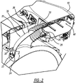
Fig. 2 is a perspective cross-section view of a duct and exhaust housing of the combination washer/dryer machine shown inFig. 1 ; -
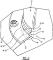
Fig. 3 is an enlarged perspective section view of an inlet end of the duct shown inFig. 2 ; -
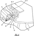
Fig. 4 is an enlarged perspective section view of an outlet end of the duct shownFig. 2 ; -
Fig. 5 is a perspective cross-section view of a second embodiment of a duct and exhaust housing; and -
Fig. 6 is an exploded perspective view of the duct shown inFig. 5 . - Turning to the figures, an appliance such as a combination washer/dryer machine is illustrated and designated with the
reference numeral 10. The combination washer/dryer machine 10 includes a housing orcabinet 12 with adoor 14 enabling access into the tub/drum assembly 16. The tub/drum assembly 16 includes atub 18 and aduct 20 to transfer processed air from the tub/drum assembly 16 into anexhaust housing 19. - The
duct 20 includes aninlet end 22 connected with atub exhaust outlet 24 and anoutlet end 26 that is connected to aninlet 28 of theexhaust housing 19. Theduct 20 is flexible and generally manufactured from an elastomeric material. Theduct 20 includes abellows 30 positioned adjacent to theoutlet end 26. Theduct 20 includes abody 34 that has a hollow conduit construction with a substantiallyconstant diameter portion 36, forming a cylinder, near theinlet end 22. Atapered conduit section 38 extends to thebellows 30 that is coupled with theinlet 28 of theexhaust housing 19. The outward taper enables the air to exit thetub 18 and move into theexhaust housing 19. - The
inlet end 22 of theduct 20 includes anattachment portion 40 to enable securement of theduct 20 with thetub 18. Theattachment portion 40 includes agroove 42 for receiving acollar 44. Thecollar 44 is fastened to thetub 18 to maintain theinlet end 22 in contact with thetub 18. Aflange 46 defines one end of thegroove 42. Theflange 46 includes a plurality of peaks andvalleys 48, 50 that extend around the periphery of theflange 46. Likewise, thecollar 44 is ring shaped and has a complementary plurality of peaks andvalleys 52, 54 that correspond to the peaks andvalleys 48, 50 of theflange 46 to provide an interlocking connection between the two. Thus, a tongue and groove connection is provided by the peaks and valleys (48, 50 and 52, 54) to secure theinlet end 22 of theduct 20 with thecollar 44 which, in turn, is coupled with thetub 18. - The
outlet end 26 of theduct 20 includes anattachment mechanism 60. Theattachment mechanism 60 includes agroove 62 and aflange 64. Thegroove 62 enables aflange 66 of theexhaust housing 19 to be positioned into thegroove 62. Theduct flange 64 has a plurality ofpeaks 68 and valleys 70 provided about its periphery to engage with a plurality ofpeaks 72 and valleys 74 in theexhaust flange 66. Thus, the outlet end 26 of theduct 20 is interlocked with theexhaust housing 19. This tongue and groove arrangement provides the interlocking between the two so that a strong securement is provided between theduct 20 andexhaust housing 19. Theexhaust housing 19 may include alint collector 80 provided along an air flow path that is aligned with theflexible duct 20. Thus, as the air exits thetub 18, it is directed into theexhaust housing 19 and through thelint collector 80. - Thus, the
bellows 30 provide compressive and expansive movement of theduct 20 in response to movement of the tub/drum assembly 16 during the washing and drying cycles. Also, theflexible duct 20 withstands heat during the drying cycle while providing movement to enable a connection between the dynamic tub/drum assembly 16 and thestatic exhaust housing 19. Additionally, theflexible duct 20 compensates for vibration during the movement of the tub/drum assembly 16 during the washing and drying cycles. The tongue and groove connections at theinlet end 22 and outlet end 26 of theduct 20 maintain a positive connection between theflexible duct 20 and thetub 18 and between theflexible duct 20 and theexhaust housing 19, respectively. - Turning to
Figs. 5 and6 , a second embodiment of the duct 20' is shown. The elements that are the same will be identified with the same reference numbers. The difference is that duct 20' is a two-piece duct. - The duct 20' is a two-piece duct with a
duct portion 21 and bellows 30'. Theduct portion 21 includes aninlet end 22 connected with thetub exhaust outlet 24. Theduct portion 21 may be flexible or rigid and generally manufactured from plastic material. The bellows 30' includes anoutlet end 26. - The
duct portion 21 is of a two-piececonstruction including halves seal 27 is positioned between the twohalves more fasteners 29. Additionally, thehalves portions ring 35.Flanges portions duct portion 21 with thetub 18. The twohalves bellows receiving portion 144 that is U-shaped withlegs 143 and aweb 145. One bellowsend 151 is positioned over one of thelegs 143 and seats in theweb 145. Aclamp 147 is positioned over the bellows 30' to retain it onto theduct portion 21. Theduct portion 21 has a hollow conduit construction with aconstant diameter portion 36 near theinlet end 22 and atapered conduit section 38 that extends from theconstant diameter portion 36 to couple with the bellows 30'. The outward taper enables the air to exit thetub 18 and move into theexhaust housing 19. - The attachment portion 40' enables securement of the
duct portion 21 with thetub 18. The attachment portion 40' includes aseal 41 and acollar 43. Theseal 41 is placed on thetub 18 and includes apertures to receivefasteners 51. Thecollar 43 includes aflange 45 that extends into thering 35. Theflange 45 hasextensions 47 that are positioned betweenflanges collar 43 with theduct portion 21. Likewise, thecollar 43 is ring shaped with a plurality of apertures to receivefasteners 51 to secure thecollar 43, seals 41 andduct portion 21 with thetub 18. - The
exhaust housing 19 may include an attachment mechanism 60', which has a similar construction to thebellows receiving portion 144 on theduct portion 21. Thus, the bellows 30' fits over the attachment mechanism 60' and is secured by aclamp 147. Also, the bellows 30' andexhaust housing 19 could have a tongue and groove arrangement between the bellows 30' andexhaust housing 19, as previously described. - Thus, the bellows 30' provide compressive and expansive movement of the duct 20' in response to movement of the tub/
drum assembly 16 during the washing and drying cycles. Also, the flexible duct 20' withstands heat during the drying cycle, while providing movement to enable a connection between the dynamic tub/drum assembly 16 and thestatic exhaust housing 19. Additionally, the flexible duct 20' compensates for vibration during the movement of the tub/drum assembly 16 during the washing and drying cycles. The connections at theinlet end 22 and outlet end 26 of the duct 20' maintain a positive connection between the flexible duct 20' and thetub 18 and between the flexible duct 20' and theexhaust housing 19, respectively. - The foregoing description of the embodiments has been provided for purposes of illustration and description. It is not intended to be exhaustive or to limit the disclosure. Individual elements or features of a particular embodiment are generally not limited to that particular embodiment, but, where applicable, are interchangeable and can be used in a selected embodiment, even if not specifically shown or described. The same may also be varied in many ways. Such variations are not to be regarded as a departure from the disclosure, and all such modifications are intended to be included within the scope of the disclosure.
Claims (15)
- A combination washer/dryer machine (10), comprising:a cabinet (12);a tub/drum assembly (16) positioned inside the cabinet (12), the tub/drum assembly (16) including a tub (18) with a tub exhaust outlet (24);a duct (20, 20') having an inlet end (22) and an outlet end (26), the inlet end (22) connected to the tub exhaust outlet (24) and the outlet end (26) connected to an exhaust housing (19);a bellows (30, 30') positioned between the inlet end (22) and the outlet end (26) of the duct (20, 20'), the bellows (30, 30') is constructed to compress and expand with movement of the tub/drum assembly (16) during washing and/or drying cycles; anda collar (43, 44) that is fastened to the tub (18) to maintain the inlet end (22) of the duct (20, 20') in contact with the tub (18) and secure the inlet end (22) of the duct (20, 20') with the tub (18).
- The combination washer/dryer machine (10) according to Claim 1, wherein the collar (43, 44) is ring shaped and has a plurality of apertures that are configured to receive fasteners (51) that secure the collar (43, 44) to the tub (18).
- The combination washer/dryer machine according to Claim 1 or 2, wherein the duct (20') has an attachment portion (40') to enable securement of the duct (20') with the tub (18) and wherein the attachment portion (40') includes a seal (41) that is placed on the tub (18).
- The combination washer/dryer machine according to Claim 3, wherein the seal (41) includes apertures to receive the fasteners (51).
- The combination washer/dryer machine (10) according to Claim 1 or 2, wherein the inlet end (22) of the duct (20) includes an attachment portion (40) that includes a groove (42) that receives the collar (44) to provide a tongue and groove connection at the inlet end (22) of the duct (20).
- The combination washer/dryer machine according to Claim 5, wherein the attachment portion (40) of the duct (20) includes a flange (46) with a plurality of peaks and valleys (48, 50) and the collar (44) has complementary peaks and valleys (52, 54) that correspond to the peaks and valleys (48, 50) of the flange (46) to provide an interlocking connection between the collar (44) and the flange (46) to secure to the inlet end (22) of the duct (20) with the collar (44), which is coupled with the tub (18).
- The combination washer/dryer machine according to any one of the preceding Claims, wherein the outlet end (26) of the duct (20, 20') includes an attachment mechanism (60) that includes a groove (62) that receives an exhaust flange (66) positioned on the exhaust housing (19) to provide a tongue and groove arrangement at the outlet end (26) of the duct (20, 20') that interlocks the outlet end (26) of the duct (20, 20') with the exhaust housing (19).
- The combination washer/dryer machine according to Claim 7, wherein the attachment mechanism (60) includes a duct flange (64) with a plurality of peaks and valleys (68, 70) and the exhaust flange (66) includes a plurality of corresponding peaks and valleys (72, 74) that engage the plurality of peaks and valleys (68, 70) in the duct flange (64) to interlock the outlet end (26) of the duct (20, 20') with the exhaust housing (19).
- The combination washer/dryer machine according to any of Claims 1 to 4, wherein the duct (20') includes a duct portion (21) that has a two-piece construction and includes two halves (23, 25).
- The combination washer/dryer machine according to Claim 9, wherein the two halves (23, 25) of the duct portion (21) include connection portions (31, 33) that form a ring (35) and wherein the collar (43) includes a flange (45) that extends into the ring (35).
- The combination washer/dryer machine according to Claim 10, wherein the two halves (23, 25) of the duct portion (21) include flanges (37, 39) that extend from the connection portions (31, 33) and wherein the flange (45) of the collar (43) has extensions 47 that are positioned between flanges (37, 39) to secure the collar (43) with the duct portion (21).
- The combination washer/dryer machine according to any one of Claims 9-11, wherein a seal (27) is positioned between the two halves (23, 25) of the duct portion (21) and the two halves (23, 25) of the duct portion (21) are secured in position by one or more fasteners (29).
- The combination washer/dryer machine (10) according to any one of Claims 9-12, wherein the bellows (30') are positioned adjacent to the outlet end (26) of the duct (20').
- The combination washer/dryer machine (10) according to Claim 13, wherein each of the two halves (23, 25) of the duct portion (21) include a bellows receiving portion (144) that is U-shaped with legs (143) and a web (145) and wherein one end (151) of the bellows (30') is positioned over one of the legs (143) and seats in the web (145).
- The combination washer/dryer machine according to any of previous Claims, wherein the duct (20, 20') includes a body (34) that has a hollow conduit construction with a substantially constant diameter portion (36) forming a cylinder near the inlet end (22) of the duct (20, 20') and a tapered conduit section (38) that extends from the substantially constant diameter portion (36) to the bellows (30, 30').
Applications Claiming Priority (1)
| Application Number | Priority Date | Filing Date | Title |
|---|---|---|---|
| US17/307,136 US20220356623A1 (en) | 2021-05-04 | 2021-05-04 | Method And Apparatus For Transferring Process Air In A Combo Washer/Dryer Unit |
Publications (1)
| Publication Number | Publication Date |
|---|---|
| EP4086381A1 true EP4086381A1 (en) | 2022-11-09 |
Family
ID=81325330
Family Applications (1)
| Application Number | Title | Priority Date | Filing Date |
|---|---|---|---|
| EP22168271.9A Withdrawn EP4086381A1 (en) | 2021-05-04 | 2022-04-13 | Method and apparatus for transferring process air in a combo washer/dryer unit |
Country Status (3)
| Country | Link |
|---|---|
| US (1) | US20220356623A1 (en) |
| EP (1) | EP4086381A1 (en) |
| CN (1) | CN115305689A (en) |
Citations (4)
| Publication number | Priority date | Publication date | Assignee | Title |
|---|---|---|---|---|
| US5199190A (en) * | 1990-11-19 | 1993-04-06 | Champion Furnace Pipe Company | Universal appliance venting assembly |
| EP2894251A2 (en) * | 2014-01-06 | 2015-07-15 | Samsung Electronics Co., Ltd | Washer dryer and method for controlling the same |
| WO2018066805A1 (en) * | 2016-10-05 | 2018-04-12 | Samsung Electronics Co., Ltd. | Washing and drying machine |
| CN111485403A (en) * | 2019-01-28 | 2020-08-04 | 无锡小天鹅电器有限公司 | Washing outer barrel and clothes treatment device |
Family Cites Families (15)
| Publication number | Priority date | Publication date | Assignee | Title |
|---|---|---|---|---|
| CN2449124Y (en) * | 2000-10-12 | 2001-09-19 | 建造金属工业股份有限公司 | Pipe joint structure of storage tank of electric water heater |
| KR100927895B1 (en) * | 2002-12-30 | 2009-11-23 | 엘지전자 주식회사 | Aerator for Drum Washing Machine |
| CN200993286Y (en) * | 2006-12-14 | 2007-12-19 | 范世峰 | Plastic pipeline bell and spigot joint |
| US8336923B2 (en) * | 2010-06-18 | 2012-12-25 | Imperial Sheet Metal, Ltd. | Dryer duct elbow |
| KR101160510B1 (en) * | 2011-11-29 | 2012-06-28 | 주식회사 우진아이엔에스 | Adapter for length adjustment of semiconductor exhaust air duct |
| CN203229801U (en) * | 2013-03-14 | 2013-10-09 | 宁国市生力实业有限公司 | Drying bellows for washing machine |
| CN103322379A (en) * | 2013-06-28 | 2013-09-25 | 无锡市伟丰印刷机械厂 | Petroleum pipeline water-proof pipe fitting |
| CN106029972B (en) * | 2014-03-21 | 2019-01-22 | 伊莱克斯家用电器股份公司 | clothes dryer |
| JP6738196B2 (en) * | 2016-05-19 | 2020-08-12 | シャープ株式会社 | Washing and drying machine |
| US10458058B1 (en) * | 2016-07-07 | 2019-10-29 | Lambro Industries, Inc. | 90 degree adjustable close elbow |
| WO2019192774A1 (en) * | 2018-04-02 | 2019-10-10 | Arcelik Anonim Sirketi | Washing machine comprising a bellow |
| CN111485409B (en) * | 2019-01-28 | 2022-03-22 | 无锡小天鹅电器有限公司 | Washing outer barrel and clothes treatment device |
| CN210318996U (en) * | 2019-07-25 | 2020-04-14 | 昆山一二三环保工程技术有限公司 | Novel elbow and flange |
| IT201900016712A1 (en) * | 2019-09-19 | 2021-03-19 | Candy Spa | LAUNDRY MACHINE |
| CN212533469U (en) * | 2020-01-22 | 2021-02-12 | 杭州乐途途智能科技有限公司 | Arc-shaped air guide pipe of heater for drying wardrobe |
-
2021
- 2021-05-04 US US17/307,136 patent/US20220356623A1/en not_active Abandoned
-
2022
- 2022-04-13 EP EP22168271.9A patent/EP4086381A1/en not_active Withdrawn
- 2022-05-05 CN CN202210479256.XA patent/CN115305689A/en active Pending
Patent Citations (4)
| Publication number | Priority date | Publication date | Assignee | Title |
|---|---|---|---|---|
| US5199190A (en) * | 1990-11-19 | 1993-04-06 | Champion Furnace Pipe Company | Universal appliance venting assembly |
| EP2894251A2 (en) * | 2014-01-06 | 2015-07-15 | Samsung Electronics Co., Ltd | Washer dryer and method for controlling the same |
| WO2018066805A1 (en) * | 2016-10-05 | 2018-04-12 | Samsung Electronics Co., Ltd. | Washing and drying machine |
| CN111485403A (en) * | 2019-01-28 | 2020-08-04 | 无锡小天鹅电器有限公司 | Washing outer barrel and clothes treatment device |
Also Published As
| Publication number | Publication date |
|---|---|
| US20220356623A1 (en) | 2022-11-10 |
| CN115305689A (en) | 2022-11-08 |
Similar Documents
| Publication | Publication Date | Title |
|---|---|---|
| US5212969A (en) | Drum type washing apparatus and method of processing the wash using said apparatus | |
| US11795601B2 (en) | Maximizing the dry rate of clothes tumbling combination washer/dryer with a seal | |
| US12031255B2 (en) | Front load all-in-one washer/dryer combo reverse airflow system | |
| US20170044707A1 (en) | Clothes dryer with a drum seal | |
| CN222541094U (en) | Clothes processing equipment | |
| US20220356623A1 (en) | Method And Apparatus For Transferring Process Air In A Combo Washer/Dryer Unit | |
| CN111979693A (en) | Device for washing and drying objects and method for operating such a device | |
| IT9034075U1 (en) | AIR CIRCULATION DUCT FOR BIANCH ERIA DRYING MACHINE | |
| JP7698138B2 (en) | Clothes Processing Equipment | |
| JP2012061168A (en) | Washing and drying machine | |
| JP7644312B2 (en) | Clothes Processing Equipment | |
| CN214459020U (en) | Laundry treatment drum for laundry treatment apparatus with drying function and laundry treatment apparatus | |
| CN115198486B (en) | A door structure and clothing handling device | |
| KR102925627B1 (en) | Laundry treating apparatus | |
| CN118727382A (en) | Clothes treatment equipment | |
| CN222008430U (en) | Clothes treatment equipment | |
| RU2835654C2 (en) | Washing machine | |
| KR102530175B1 (en) | Washing machine | |
| EP3374563B1 (en) | A washer/dryer comprising a condenser | |
| US2685139A (en) | Drier cylinder, particularly for papermaking machinery | |
| EP2221521A1 (en) | Fluid-bearing appliance with an improved pipe connector | |
| CN223316955U (en) | Clothes treatment equipment | |
| CN223061300U (en) | Water inlet structure and clothing processing equipment | |
| CN219410274U (en) | Shaft sealing device of motor and washing machine | |
| KR102771867B1 (en) | Laundry Treatment Apparatus |
Legal Events
| Date | Code | Title | Description |
|---|---|---|---|
| PUAI | Public reference made under article 153(3) epc to a published international application that has entered the european phase |
Free format text: ORIGINAL CODE: 0009012 |
|
| STAA | Information on the status of an ep patent application or granted ep patent |
Free format text: STATUS: THE APPLICATION HAS BEEN PUBLISHED |
|
| AK | Designated contracting states |
Kind code of ref document: A1 Designated state(s): AL AT BE BG CH CY CZ DE DK EE ES FI FR GB GR HR HU IE IS IT LI LT LU LV MC MK MT NL NO PL PT RO RS SE SI SK SM TR |
|
| RAP3 | Party data changed (applicant data changed or rights of an application transferred) |
Owner name: WHIRLPOOL CORPORATION |
|
| STAA | Information on the status of an ep patent application or granted ep patent |
Free format text: STATUS: THE APPLICATION IS DEEMED TO BE WITHDRAWN |
|
| 18D | Application deemed to be withdrawn |
Effective date: 20230510 |