EP4086369B1 - Method for preventing short circuiting between inner surface of capillary tube or special-shaped tube and conductive electrode - Google Patents
Method for preventing short circuiting between inner surface of capillary tube or special-shaped tube and conductive electrode Download PDFInfo
- Publication number
- EP4086369B1 EP4086369B1 EP21893475.0A EP21893475A EP4086369B1 EP 4086369 B1 EP4086369 B1 EP 4086369B1 EP 21893475 A EP21893475 A EP 21893475A EP 4086369 B1 EP4086369 B1 EP 4086369B1
- Authority
- EP
- European Patent Office
- Prior art keywords
- electrode
- shaped tube
- short circuit
- preventing short
- molecular polymer
- Prior art date
- Legal status (The legal status is an assumption and is not a legal conclusion. Google has not performed a legal analysis and makes no representation as to the accuracy of the status listed.)
- Active
Links
Images

Classifications
-
- C—CHEMISTRY; METALLURGY
- C25—ELECTROLYTIC OR ELECTROPHORETIC PROCESSES; APPARATUS THEREFOR
- C25D—PROCESSES FOR THE ELECTROLYTIC OR ELECTROPHORETIC PRODUCTION OF COATINGS; ELECTROFORMING; APPARATUS THEREFOR
- C25D11/00—Electrolytic coating by surface reaction, i.e. forming conversion layers
- C25D11/02—Anodisation
- C25D11/26—Anodisation of refractory metals or alloys based thereon
-
- C—CHEMISTRY; METALLURGY
- C25—ELECTROLYTIC OR ELECTROPHORETIC PROCESSES; APPARATUS THEREFOR
- C25D—PROCESSES FOR THE ELECTROLYTIC OR ELECTROPHORETIC PRODUCTION OF COATINGS; ELECTROFORMING; APPARATUS THEREFOR
- C25D11/00—Electrolytic coating by surface reaction, i.e. forming conversion layers
- C25D11/005—Apparatus specially adapted for electrolytic conversion coating
-
- C—CHEMISTRY; METALLURGY
- C25—ELECTROLYTIC OR ELECTROPHORETIC PROCESSES; APPARATUS THEREFOR
- C25D—PROCESSES FOR THE ELECTROLYTIC OR ELECTROPHORETIC PRODUCTION OF COATINGS; ELECTROFORMING; APPARATUS THEREFOR
- C25D11/00—Electrolytic coating by surface reaction, i.e. forming conversion layers
- C25D11/02—Anodisation
- C25D11/04—Anodisation of aluminium or alloys based thereon
-
- C—CHEMISTRY; METALLURGY
- C25—ELECTROLYTIC OR ELECTROPHORETIC PROCESSES; APPARATUS THEREFOR
- C25D—PROCESSES FOR THE ELECTROLYTIC OR ELECTROPHORETIC PRODUCTION OF COATINGS; ELECTROFORMING; APPARATUS THEREFOR
- C25D11/00—Electrolytic coating by surface reaction, i.e. forming conversion layers
- C25D11/02—Anodisation
- C25D11/34—Anodisation of metals or alloys not provided for in groups C25D11/04 - C25D11/32
-
- C—CHEMISTRY; METALLURGY
- C25—ELECTROLYTIC OR ELECTROPHORETIC PROCESSES; APPARATUS THEREFOR
- C25D—PROCESSES FOR THE ELECTROLYTIC OR ELECTROPHORETIC PRODUCTION OF COATINGS; ELECTROFORMING; APPARATUS THEREFOR
- C25D17/00—Constructional parts, or assemblies thereof, of cells for electrolytic coating
- C25D17/005—Contacting devices
-
- C—CHEMISTRY; METALLURGY
- C25—ELECTROLYTIC OR ELECTROPHORETIC PROCESSES; APPARATUS THEREFOR
- C25D—PROCESSES FOR THE ELECTROLYTIC OR ELECTROPHORETIC PRODUCTION OF COATINGS; ELECTROFORMING; APPARATUS THEREFOR
- C25D17/00—Constructional parts, or assemblies thereof, of cells for electrolytic coating
- C25D17/10—Electrodes, e.g. composition, counter electrode
Definitions
- the invention relates to the field of electrode material short-circuit prevention, in particular to a method for preventing short circuit of a conductive electrode for an inner surface of a capillary tube or a special-shaped tube.
- Electrochemical treatment serves as one of branches of chemical treatment and is widely applied to the fields of energy, biology, environment, metal material surface modification and the like.
- the electrochemical reaction device is generally composed of a power supply, a cathode, an anode, an electrolyte and the like.
- the cathode and the anode are made of conductive materials so as to ensure conduction of system current. In an open system, the distance between the cathode and the anode is large and can be adjusted, and in the reaction process, contact caused by external force (such as bubble floating and stress of liquid flowing on the cathode and the anode) is avoided.
- the distance between the cathode and the anode is relatively small, so that the cathode and the anode are very easy to contact under the action of external force, and the reaction cannot be smoothly carried out due to short circuit of the cathode and the anode.
- the capillary tube or the special-shaped tube serves as the anode, and a cathode filament needs to be arranged in the anode; however, the prior art can not guarantee that short circuit of the cathode filament and the capillary tube or the special-shaped tube in the reaction process will not happen, let alone preparation of the superwetting coating on the inner surface of the capillary tube or the special-shaped tube. Therefore, it is urgent to develop a method for preventing short circuit of a conductive electrode for an inner surface of a capillary tube or a shaped tube, which is convenient to operate, wide in applicability and low in cost.
- WO2014/060333 discloses an elongated inner electrode for the anodic oxidation of a metal tube, around which a PVC-coated metal wire is wound.
- the invention aims to provide a method for preventing short circuit of a conductive electrode for an inner surface of a shaped tube, which is characterized by comprising the following steps: preparing a high-molecular polymer solution; the solvent of the solution being one of N-methylpyrrolidone (NMP) and N,N-dimethylformamide (DMF), and the solute of the solution being one of polylactic acid (PLA) and polyvinyl chloride (PVC), and cleaning and drying an electrode used for penetrating into the shaped tube, and then cladding the surface of the electrode with a high-molecular polymer. After the electrode penetrates into the shaped tube, the capillary tube or the special-shaped tube needs to be subjected to electrochemical treatment.
- NMP N-methylpyrrolidone
- DMF N,N-dimethylformamide
- PVC polyvinyl chloride
- the shaped tube is immersed in electrolyte to be subjected to surface treatment, the penetrated electrode serves as a cathode or an anode, and the other electrode is the shaped tube (the shaped tube and the electrode are all made of conductive materials).
- the concentration of the high-molecular polymer solution is 10-100g/L.
- the electrode is an electrode wire made of stainless steel, copper, iron, platinum or titanium.
- cladding of the high-molecular polymer means that the high-molecular polymer solution is coated and dried.
- the thickness of a high-molecular polymer film cladded on the electrode is 1-50 ⁇ m.
- the shaped tube is a capillary metal tube, a needle tube for detection, a heat dissipation copper tube for a mobile phone or a spiral titanium tube for condensation.
- the cleaning time of the electrode is 0.5-4 hours
- the drying temperature is 50-80 DEG C
- the drying time is 2-5 hours.
- the temperature for drying the electrode is 50-80 DEG C, and the drying time is 0.5-4 hours.
- a molecular polymer solution with polyvinylidene fluoride serving as the solute and N-methylpyrrolidone serving as the solvent needs to be prepared, and the concentration of the molecular polymer solution is 10 g/L.
- the method includes the following steps:
- the uncladded stainless steel wire with the diameter of 0.2 mm is metal, and when the uncladded stainless steel wire is independently used as a cathode in an anodic oxidation method, only 0.2 mm of residual space is left in a tube.
- the cathode stainless steel wire is very easy to contact with the anode capillary titanium tube to cause short circuit because the electrolyte has a scouring effect on the cathode stainless steel wire. As shown in Fig.
- the outer surface of the treated cathode stainless steel wire is coated with a layer of high-molecular polymer diaphragm with the thickness of about 20-30 ⁇ m by cladding a high-molecular polymer film, and the layer of diaphragm can separate the cathode from the anode during anodic oxidation, so that an electric field is not shielded while short circuit is prevented, and anodic oxidation can be carried out.
- the length of the titanium dioxide nanotube array prepared by anodic oxidation is about 3 ⁇ m, and the titanium dioxide nanotube array has the characteristics of smooth tube wall, good opening and the like.
- the method has the advantages of convenience in operation, wide application range, low cost and the like.
Landscapes
- Chemical & Material Sciences (AREA)
- Engineering & Computer Science (AREA)
- Chemical Kinetics & Catalysis (AREA)
- Electrochemistry (AREA)
- Materials Engineering (AREA)
- Metallurgy (AREA)
- Organic Chemistry (AREA)
- Electroplating Methods And Accessories (AREA)
- Electrodes For Compound Or Non-Metal Manufacture (AREA)
- Water Treatment By Electricity Or Magnetism (AREA)
- Electrolytic Production Of Non-Metals, Compounds, Apparatuses Therefor (AREA)
Description
- The invention relates to the field of electrode material short-circuit prevention, in particular to a method for preventing short circuit of a conductive electrode for an inner surface of a capillary tube or a special-shaped tube.
- Electrochemical treatment serves as one of branches of chemical treatment and is widely applied to the fields of energy, biology, environment, metal material surface modification and the like. The electrochemical reaction device is generally composed of a power supply, a cathode, an anode, an electrolyte and the like. The cathode and the anode are made of conductive materials so as to ensure conduction of system current. In an open system, the distance between the cathode and the anode is large and can be adjusted, and in the reaction process, contact caused by external force (such as bubble floating and stress of liquid flowing on the cathode and the anode) is avoided. However, for a confined semi-closed system (such as a capillary tube and a special-shaped tube), the distance between the cathode and the anode is relatively small, so that the cathode and the anode are very easy to contact under the action of external force, and the reaction cannot be smoothly carried out due to short circuit of the cathode and the anode. For example, when an electrochemical reaction method is adopted to carry out superwetting modification on the inner surface of the capillary tube or the special-shaped tube such as the capillary metal tube, the needle tube for detection, the heat dissipation copper tube for the mobile phone, the spiral titanium tube for condensation and the like, the capillary tube or the special-shaped tube serves as the anode, and a cathode filament needs to be arranged in the anode; however, the prior art can not guarantee that short circuit of the cathode filament and the capillary tube or the special-shaped tube in the reaction process will not happen, let alone preparation of the superwetting coating on the inner surface of the capillary tube or the special-shaped tube. Therefore, it is urgent to develop a method for preventing short circuit of a conductive electrode for an inner surface of a capillary tube or a shaped tube, which is convenient to operate, wide in applicability and low in cost.
-
WO2014/060333 discloses an elongated inner electrode for the anodic oxidation of a metal tube, around which a PVC-coated metal wire is wound. - The invention aims to provide a method for preventing short circuit of a conductive electrode for an inner surface of a shaped tube, which is characterized by comprising the following steps: preparing a high-molecular polymer solution; the solvent of the solution being one of N-methylpyrrolidone (NMP) and N,N-dimethylformamide (DMF), and the solute of the solution being one of polylactic acid (PLA) and polyvinyl chloride (PVC), and cleaning and drying an electrode used for penetrating into the shaped tube, and then cladding the surface of the electrode with a high-molecular polymer. After the electrode penetrates into the shaped tube, the capillary tube or the special-shaped tube needs to be subjected to electrochemical treatment. According to the invention, the shaped tube is immersed in electrolyte to be subjected to surface treatment, the penetrated electrode serves as a cathode or an anode, and the other electrode is the shaped tube (the shaped tube and the electrode are all made of conductive materials).
- Furthermore, the concentration of the high-molecular polymer solution is 10-100g/L. Furthermore, the electrode is an electrode wire made of stainless steel, copper, iron, platinum or titanium.
- Furthermore, cladding of the high-molecular polymer means that the high-molecular polymer solution is coated and dried.
- Furthermore, the thickness of a high-molecular polymer film cladded on the electrode is 1-50 µm.
- Furthermore, the shaped tube is a capillary metal tube, a needle tube for detection, a heat dissipation copper tube for a mobile phone or a spiral titanium tube for condensation.
- Furthermore, the cleaning time of the electrode is 0.5-4 hours, the drying temperature is 50-80 DEG C, and the drying time is 2-5 hours.
- Furthermore, after the high-molecular polymer solution is coated, the temperature for drying the electrode is 50-80 DEG C, and the drying time is 0.5-4 hours.
- Compared with the prior art, the method has the following remarkable advantages and beneficial effects:
- 1. The problem that the cathode and the anode are prone to short circuit in a confined semi-closed system is solved;
- 2. The operation is convenient, and the process production difficulty is low; and
- 3. The usability is wide, and the sizes and materials of the cathode and the anode are not limited.
-
-
Fig. 1 is a process schematic diagram for preparing the short-circuit-proof electrode cladded with the high-molecular polymer. -
Fig. 2 is a scanning electron micrograph of the cathode filament cladded with the high-molecular polymer film. In the graphs, (a) is the surface graph of the cathode filament, (b) is the cross-sectional graph of the cathode filament, (c) is the surface graph of the film before electrochemical reaction, and (d) is the surface graph of the film after electrochemical reaction. -
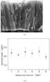
Fig. 3 is a scanning electron micrograph of a titanium dioxide nanotube array prepared on the inner surface of a titanium tube with the inner diameter of 0.4 mm by using an electrochemical anodic oxidation method according to the method disclosed by the invention. -
Fig. 4 is the statistical result of the uniformity of the titanium dioxide nanotube array prepared on the inner surface of the titanium tube with the inner diameter of 0.4 mm and the length of 70mm by using the electrochemical anodic oxidation method according to the method disclosed by the invention. - The invention is further explained in combination with the following embodiments, but the subject range of the invention is not understood to be only limited to the following embodiments. Various substitutions and changes made according to the general technical knowledge and frequently used means in the art shall be included in the protection scope of the invention, which is defined by the appended claims.
- According to the method for preventing short circuit of the conductive electrode for the inner surface of the capillary tube or the special-shaped tube, a molecular polymer solution with polyvinylidene fluoride serving as the solute and N-methylpyrrolidone serving as the solvent needs to be prepared, and the concentration of the molecular polymer solution is 10 g/L.
- The method includes the following steps:
- (1) ultrasonic oscillation cleaning was carried out on a stainless steel wire electrode with the diameter of 0.2 mm in a detergent, alcohol and deionized water sequentially, and the cleaning time was 0.5 h separately;
- (2) the stainless steel wire was blow-dried through a nitrogen spray gun;
- (3) the stainless steel wire was dried, the drying temperature was 50 DEG C, and the drying time was 1 h;
- (4) the dried stainless steel wire was taken as a substrate, and the surface of the substrate was repeatedly coated with the high-molecular polymer solution for 20-25 times;
- (5) the stainless steel wire coated with the polyvinylidene fluoride solution was dried, the drying temperature was 50 DEG C, and the drying time was 2 h; and
- (6) the stainless steel wire was made to penetrate into a dry capillary titanium tube with the inner diameter of 0.4 mm, a power supply was connected, and the electrolyte was introduced for electrochemical treatment (anodic oxidation treatment).
- Relevant performance data of the embodiment is as follows:
In a contrast experiment, the uncladded stainless steel wire with the diameter of 0.2 mm is metal, and when the uncladded stainless steel wire is independently used as a cathode in an anodic oxidation method, only 0.2 mm of residual space is left in a tube. When the electrolyte is introduced, the cathode stainless steel wire is very easy to contact with the anode capillary titanium tube to cause short circuit because the electrolyte has a scouring effect on the cathode stainless steel wire. As shown inFig. 2 , the outer surface of the treated cathode stainless steel wire is coated with a layer of high-molecular polymer diaphragm with the thickness of about 20-30 µm by cladding a high-molecular polymer film, and the layer of diaphragm can separate the cathode from the anode during anodic oxidation, so that an electric field is not shielded while short circuit is prevented, and anodic oxidation can be carried out. As shown inFig. 3 , the length of the titanium dioxide nanotube array prepared by anodic oxidation is about 3 µm, and the titanium dioxide nanotube array has the characteristics of smooth tube wall, good opening and the like.Fig. 4 shows the length statistics of the nanotube array at different positions of the inner surface of the capillary titanium type tube, which indicates that the thickness of the prepared nano coating is uniform and controllable. Meanwhile, the method has the advantages of convenience in operation, wide application range, low cost and the like. - The difference from the
embodiment 1 is that: - 1. In the step (1), the electrode was a platinum wire, and the diameter of the platinum wire was 0.4 mm.
- 2. In the step (4), polylactic acid (PLA) served as the solute of the high-molecular polymer, N-methylpyrrolidone (NMP) served as the solvent, the solution concentration was 20 g/L, and the coating number was 20-25 times.
- 3. In the step (6), the anode was a stainless steel capillary tube with the inner diameter of 1mm.
- The difference from the
embodiment 1 is that: - 1. In the step (1), the electrode was a copper wire, and the diameter of the copper wire was 0.6 mm.
- 2. In the step (4), polyvinyl chloride (PVC) served as the solute of the high-molecular polymer, N-methylpyrrolidone (NMP) served as the solvent, the solution concentration was 10 g/L, and the coating number was 15-20 times.
- 3. In the step (6), the anode was an aluminum alloy capillary tube with the inner diameter of 1.5 mm.
- The difference from the
embodiment 1 is that: - 1. In the step (1), the electrode was iron wire, and the diameter of the iron wire was 1mm.
- 2. In the step (4), polyvinylidene fluoride (PVDF) served as the solute of the high-molecular polymer, N,N-dimethylformamide (DMF) served as the solvent, the solution concentration was 15 g/L, and the coating number was 10-15 times.
- 3. In the step (6), the anode was a spiral capillary titanium heat exchange tube with the inner diameter of 2.5 mm.
- The difference from the
embodiment 1 is that: - 1. In the step (1), the electrode was a titanium wire, and the diameter of the titanium wire was 1.5 mm.
- 2. In the step (6), the anode was a special-shaped copper alloy tube with a rectangular inner section (the length was 5.5 mm and the width was 3.0 mm).
- The difference from the
embodiment 1 is that: - 1. In the step (1), the electrode was a titanium wire, and the diameter of the titanium wire was 0.5 mm.
- 2. In the step (6), the anode was an L-shaped special-shaped titanium tube with the inner diameter of 3.0 mm.
- The difference from the
embodiment 1 is that: - 1. In the step (1), the electrode was an iron wire, and the diameter of the iron wire was 0.4 mm.
- 2. In the step (6), the anode is a T-shaped special-shaped stainless steel tube with the inner diameter of 2.5 mm.
- The difference from the
embodiment 1 is that: - 1. In the step (1), the electrode was an iron wire, and the diameter of the iron wire was 0.4 mm.
- 2. In the step (6), the anode was a V-shaped special-shaped stainless steel tube with the inner diameter of 2.5 mm.
Claims (8)
- A method for preventing short circuit of a conductive electrode for an inner surface of a shaped tube, comprising the following steps:preparing a high-molecular polymer solution, wherein the solvent of the solution is one selected from N-methylpyrrolidone (NMP) and N,N-dimethylformamide (DMF), and the solute of the solution is a high polymer material, which is one selected from polylactic acid (PLA), polyvinyl chloride (PVC);cleaning and drying an electrode to be used for penetrating into the shaped tube, and then cladding the surface of the electrode with the high-molecular polymer;using the electrode to penetrate into the shaped tube; and subjecting the shaped tube to electrochemical treatment, wherein the electrode serves as a cathode or an anode, and the shaped tube serves as the other electrode.
- The method for preventing short circuit of a conductive electrode for an inner surface of a shaped tube according to claim 1, wherein the concentration of the high-molecular polymer in the solution is 10-100 g/L.
- The method for preventing short circuit of a conductive electrode for an inner surface of a shaped tube according to claim 1 or 2, wherein the electrode is an electrode wire made of stainless steel, copper, iron, platinum or titanium.
- The method for preventing short circuit of a conductive electrode for an inner surface of a shaped tube according to claim 1 or 3, wherein the cladding of the high-molecular polymer is produced by coating with the high-molecular polymer solution and drying.
- The method for preventing short circuit of a conductive electrode for an inner surface of a shaped tube according to claim 1, wherein the high-molecular polymer cladded on the electrode forms a film of a thickness of 1-50 µm.
- The method for preventing short circuit of a conductive electrode for an inner surface of a shaped tube according to claim 1, wherein the shaped tube is a capillary metal tube, a needle tube for detection, a heat dissipation copper tube for a mobile phone, or a spiral titanium tube for condensation.
- The method for preventing short circuit of a conductive electrode for an inner surface of a shaped tube according to claim 1, wherein the cleaning time of the electrode is 0.5-4 hours, the drying temperature is 50-80°C, and the drying time is 2-5 hours.
- The method for preventing short circuit of a conductive electrode for an inner surface of a shaped tube according to claim 1, wherein
after being coated with the high-molecular polymer solution, the electrode is dried at a temperature of 50-80°C, and the drying time is 0.5-4 hours.
Applications Claiming Priority (2)
| Application Number | Priority Date | Filing Date | Title |
|---|---|---|---|
| CN202011324722.4A CN112680729B (en) | 2020-11-23 | 2020-11-23 | Short circuit prevention method for conductive electrode on inner surface of capillary tube or special tube |
| PCT/CN2021/112807 WO2022105323A1 (en) | 2020-11-23 | 2021-08-16 | Method for preventing short circuiting between inner surface of capillary tube or special-shaped tube and conductive electrode |
Publications (4)
| Publication Number | Publication Date |
|---|---|
| EP4086369A1 EP4086369A1 (en) | 2022-11-09 |
| EP4086369A4 EP4086369A4 (en) | 2023-08-23 |
| EP4086369B1 true EP4086369B1 (en) | 2024-10-30 |
| EP4086369C0 EP4086369C0 (en) | 2024-10-30 |
Family
ID=75446766
Family Applications (1)
| Application Number | Title | Priority Date | Filing Date |
|---|---|---|---|
| EP21893475.0A Active EP4086369B1 (en) | 2020-11-23 | 2021-08-16 | Method for preventing short circuiting between inner surface of capillary tube or special-shaped tube and conductive electrode |
Country Status (3)
| Country | Link |
|---|---|
| EP (1) | EP4086369B1 (en) |
| CN (1) | CN112680729B (en) |
| WO (1) | WO2022105323A1 (en) |
Families Citing this family (1)
| Publication number | Priority date | Publication date | Assignee | Title |
|---|---|---|---|---|
| CN112680729B (en) * | 2020-11-23 | 2022-10-14 | 重庆大学 | Short circuit prevention method for conductive electrode on inner surface of capillary tube or special tube |
Family Cites Families (22)
| Publication number | Priority date | Publication date | Assignee | Title |
|---|---|---|---|---|
| GB8417092D0 (en) * | 1984-07-04 | 1984-08-08 | Tecalemit Group Services Ltd | Internal electroplating of tubular/hollow workpieces |
| DE4120679C2 (en) * | 1991-06-22 | 1995-11-09 | Grimma Masch Anlagen Gmbh | Electrolysis process and electrolysis cell for gas-developing or gas-consuming electrolytic processes |
| JP3081558B2 (en) * | 1997-04-30 | 2000-08-28 | 株式会社ダイワエクセル | Inner plating method and auxiliary electrode for inner plating |
| US20030077515A1 (en) * | 2001-04-02 | 2003-04-24 | Chen George Zheng | Conducting polymer-carbon nanotube composite materials and their uses |
| US20040108215A1 (en) * | 2002-12-06 | 2004-06-10 | Com Dev Ltd. | Electroplating anode assembly |
| CN101691202B (en) * | 2009-08-11 | 2012-01-04 | 西安交通大学 | Method for preparing polyvinylidene fluoride piezo film with microstructure |
| CN102117935A (en) * | 2009-12-31 | 2011-07-06 | 珠海光宇电池有限公司 | Power battery with pole pieces fixed by using organic adhesive and manufacturing method thereof |
| KR101246827B1 (en) * | 2010-11-01 | 2013-03-28 | 주식회사 아모그린텍 | Electrode assembly, rechargeable battery using the same and method of manufacturing the same |
| CN202465932U (en) * | 2011-12-27 | 2012-10-03 | 中国航空工业第六○七研究所 | Flexible auxiliary anode for electroplating inner cavity of multi-bend waveguide |
| DE102012109812A1 (en) * | 2012-10-15 | 2014-04-17 | Noatzke Verwaltungs GmbH | Anodizing and anodizing |
| EP2953704B1 (en) * | 2013-02-06 | 2020-06-10 | Northeastern University | Filtering article containing titania nanotubes |
| KR101812194B1 (en) * | 2015-06-05 | 2017-12-27 | 경상대학교산학협력단 | Electrode, battery and method for manufacturing the electrode |
| WO2017036561A1 (en) * | 2015-09-04 | 2017-03-09 | Poligrat Gmbh | Electrode device for electrochemical workpiece machining |
| JP6697210B2 (en) * | 2016-05-27 | 2020-05-20 | 株式会社Fts | Inner surface electrode for inner surface plating of tubular article |
| WO2018107092A1 (en) * | 2016-12-09 | 2018-06-14 | The Regents Of The University Of California | Surface-functionalized tubular structures, and methods of making and using the same |
| DE102018114206A1 (en) * | 2018-06-14 | 2019-12-19 | RUHR-UNIVERSITäT BOCHUM | Biosensor and method for producing one |
| KR102524662B1 (en) * | 2019-05-09 | 2023-04-20 | 주식회사 엘지에너지솔루션 | A binder resin composition and a separator for an electrochemical device including the same |
| CN110487665A (en) * | 2019-08-23 | 2019-11-22 | 深圳市比克动力电池有限公司 | A kind of wellability detection method of pole piece |
| CN110552042A (en) * | 2019-08-27 | 2019-12-10 | 重庆大学 | Preparation method of super-wetting coating on inner surface of U-shaped titanium tube |
| CN112593281B (en) * | 2020-11-23 | 2024-10-29 | 重庆大学 | A method for preparing a super-wetting coating suitable for the inner surface of a stainless steel pipe |
| CN112680729B (en) * | 2020-11-23 | 2022-10-14 | 重庆大学 | Short circuit prevention method for conductive electrode on inner surface of capillary tube or special tube |
| CN112593280B (en) * | 2020-11-23 | 2024-07-19 | 重庆大学 | A method for preparing super hydrophobic coating on inner and outer surfaces and end faces of hollow needles |
-
2020
- 2020-11-23 CN CN202011324722.4A patent/CN112680729B/en active Active
-
2021
- 2021-08-16 EP EP21893475.0A patent/EP4086369B1/en active Active
- 2021-08-16 WO PCT/CN2021/112807 patent/WO2022105323A1/en not_active Ceased
Also Published As
| Publication number | Publication date |
|---|---|
| CN112680729A (en) | 2021-04-20 |
| EP4086369A4 (en) | 2023-08-23 |
| EP4086369C0 (en) | 2024-10-30 |
| WO2022105323A1 (en) | 2022-05-27 |
| EP4086369A1 (en) | 2022-11-09 |
| CN112680729B (en) | 2022-10-14 |
Similar Documents
| Publication | Publication Date | Title |
|---|---|---|
| US9819076B2 (en) | Intenna manufacturing method having capability to improve plating reliability | |
| JP5625141B1 (en) | Copper foil for negative electrode current collector of lithium ion secondary battery | |
| CN112593281B (en) | A method for preparing a super-wetting coating suitable for the inner surface of a stainless steel pipe | |
| CN113502476A (en) | Method for manufacturing electrode foil for solid aluminum electrolytic capacitor | |
| EP4086369A1 (en) | Method for preventing short circuiting between inner surface of capillary tube or special-shaped tube and conductive electrode | |
| Kang et al. | Microstructured nanopore-walled porous silicon as an anode material for rechargeable lithium batteries | |
| CN113373404A (en) | Copper-based thick-wall Nb3Sn film superconducting cavity and preparation method thereof | |
| JP2004139951A (en) | Separator for fuel cell and its manufacturing method | |
| Petitjean et al. | A New Oscillatory Electrochemical Phenomenon Observed in the Electropolymerization of Pyrrole in MeCN+ N (Bu) 4 PF 6 on an Iron Electrode Studied by the Ring‐Disk‐Electrode Technique | |
| CN118737776B (en) | Porous silicon-based cathode electron source and preparation method and equipment thereof | |
| US11248306B2 (en) | Anodic-oxidation equipment, anodic-oxidation method, and method for producing cathode of anodic-oxidation equipment | |
| TWI659984B (en) | Laminated body of support film for solution film formation and electrolyte membrane, and manufacturing method of electrolyte membrane using support film for solution film formation | |
| CN110112427B (en) | Preparation method of electrochemical-assisted nitrogen and phosphorus double-doped carbon-based air electrode | |
| CN118588513A (en) | Porous silicon-based electron emission source and preparation method and equipment thereof | |
| CN106645077A (en) | A preparing method of an SERS active substrate having a 'hot spot' dimension of less than 5 nm based on a novel high- and low-temperature counterboring process with a step core drill | |
| JP2009275329A (en) | Electroconductive yarn and method of producing the same | |
| KR102172627B1 (en) | Manufacturing method of titanium oxide nanotube electrode having excellent interfacial adhesion | |
| Chen et al. | Choline Chloride-Carboxylic Acid Based Deep Eutectic Solvents as Advantageous Electrolytes for Direct Electrochemical Conversion of Tin Oxide to Tin | |
| JP2861774B2 (en) | Solid electrolytic capacitors | |
| CN107385896A (en) | A kind of organic matter immersion and the method for electrochemicial oxidation carbon fiber | |
| CN110911351A (en) | A kind of method for preparing silicon oxide on the surface of silicon wafer | |
| Eftekhari | Enhanced stability of hexacyanoferrate-based modified electrodes prepared under centrifugal fields | |
| CN104746122A (en) | Method for preparing high-quality anodized aluminum template by monitoring oxide layer removal time in real time | |
| JPH11307386A (en) | Capacitor and method of manufacturing the same | |
| CN119779783B (en) | Pretreatment liquid for detecting formation foil and formation foil detection method |
Legal Events
| Date | Code | Title | Description |
|---|---|---|---|
| STAA | Information on the status of an ep patent application or granted ep patent |
Free format text: STATUS: THE INTERNATIONAL PUBLICATION HAS BEEN MADE |
|
| PUAI | Public reference made under article 153(3) epc to a published international application that has entered the european phase |
Free format text: ORIGINAL CODE: 0009012 |
|
| STAA | Information on the status of an ep patent application or granted ep patent |
Free format text: STATUS: REQUEST FOR EXAMINATION WAS MADE |
|
| 17P | Request for examination filed |
Effective date: 20220805 |
|
| AK | Designated contracting states |
Kind code of ref document: A1 Designated state(s): AL AT BE BG CH CY CZ DE DK EE ES FI FR GB GR HR HU IE IS IT LI LT LU LV MC MK MT NL NO PL PT RO RS SE SI SK SM TR |
|
| A4 | Supplementary search report drawn up and despatched |
Effective date: 20230721 |
|
| RIC1 | Information provided on ipc code assigned before grant |
Ipc: C25D 11/00 20060101ALI20230717BHEP Ipc: C25D 17/10 20060101ALI20230717BHEP Ipc: C25D 17/00 20060101ALI20230717BHEP Ipc: B82Y 40/00 20110101ALI20230717BHEP Ipc: C25D 11/04 20060101ALI20230717BHEP Ipc: C25D 11/34 20060101ALI20230717BHEP Ipc: C25D 11/26 20060101ALI20230717BHEP Ipc: C23C 26/00 20060101AFI20230717BHEP |
|
| DAV | Request for validation of the european patent (deleted) | ||
| DAX | Request for extension of the european patent (deleted) | ||
| GRAP | Despatch of communication of intention to grant a patent |
Free format text: ORIGINAL CODE: EPIDOSNIGR1 |
|
| STAA | Information on the status of an ep patent application or granted ep patent |
Free format text: STATUS: GRANT OF PATENT IS INTENDED |
|
| INTG | Intention to grant announced |
Effective date: 20240617 |
|
| GRAS | Grant fee paid |
Free format text: ORIGINAL CODE: EPIDOSNIGR3 |
|
| GRAA | (expected) grant |
Free format text: ORIGINAL CODE: 0009210 |
|
| STAA | Information on the status of an ep patent application or granted ep patent |
Free format text: STATUS: THE PATENT HAS BEEN GRANTED |
|
| AK | Designated contracting states |
Kind code of ref document: B1 Designated state(s): AL AT BE BG CH CY CZ DE DK EE ES FI FR GB GR HR HU IE IS IT LI LT LU LV MC MK MT NL NO PL PT RO RS SE SI SK SM TR |
|
| REG | Reference to a national code |
Ref country code: GB Ref legal event code: FG4D |
|
| REG | Reference to a national code |
Ref country code: CH Ref legal event code: EP |
|
| REG | Reference to a national code |
Ref country code: DE Ref legal event code: R096 Ref document number: 602021021209 Country of ref document: DE |
|
| REG | Reference to a national code |
Ref country code: IE Ref legal event code: FG4D |
|
| U01 | Request for unitary effect filed |
Effective date: 20241031 |
|
| U07 | Unitary effect registered |
Designated state(s): AT BE BG DE DK EE FI FR IT LT LU LV MT NL PT RO SE SI Effective date: 20241112 |
|
| PG25 | Lapsed in a contracting state [announced via postgrant information from national office to epo] |
Ref country code: HR Free format text: LAPSE BECAUSE OF FAILURE TO SUBMIT A TRANSLATION OF THE DESCRIPTION OR TO PAY THE FEE WITHIN THE PRESCRIBED TIME-LIMIT Effective date: 20241030 Ref country code: IS Free format text: LAPSE BECAUSE OF FAILURE TO SUBMIT A TRANSLATION OF THE DESCRIPTION OR TO PAY THE FEE WITHIN THE PRESCRIBED TIME-LIMIT Effective date: 20250228 |
|
| PG25 | Lapsed in a contracting state [announced via postgrant information from national office to epo] |
Ref country code: ES Free format text: LAPSE BECAUSE OF FAILURE TO SUBMIT A TRANSLATION OF THE DESCRIPTION OR TO PAY THE FEE WITHIN THE PRESCRIBED TIME-LIMIT Effective date: 20241030 |
|
| PG25 | Lapsed in a contracting state [announced via postgrant information from national office to epo] |
Ref country code: NO Free format text: LAPSE BECAUSE OF FAILURE TO SUBMIT A TRANSLATION OF THE DESCRIPTION OR TO PAY THE FEE WITHIN THE PRESCRIBED TIME-LIMIT Effective date: 20250130 |
|
| PG25 | Lapsed in a contracting state [announced via postgrant information from national office to epo] |
Ref country code: GR Free format text: LAPSE BECAUSE OF FAILURE TO SUBMIT A TRANSLATION OF THE DESCRIPTION OR TO PAY THE FEE WITHIN THE PRESCRIBED TIME-LIMIT Effective date: 20250131 |
|
| PG25 | Lapsed in a contracting state [announced via postgrant information from national office to epo] |
Ref country code: PL Free format text: LAPSE BECAUSE OF FAILURE TO SUBMIT A TRANSLATION OF THE DESCRIPTION OR TO PAY THE FEE WITHIN THE PRESCRIBED TIME-LIMIT Effective date: 20241030 |
|
| PG25 | Lapsed in a contracting state [announced via postgrant information from national office to epo] |
Ref country code: RS Free format text: LAPSE BECAUSE OF FAILURE TO SUBMIT A TRANSLATION OF THE DESCRIPTION OR TO PAY THE FEE WITHIN THE PRESCRIBED TIME-LIMIT Effective date: 20250130 |
|
| PG25 | Lapsed in a contracting state [announced via postgrant information from national office to epo] |
Ref country code: SM Free format text: LAPSE BECAUSE OF FAILURE TO SUBMIT A TRANSLATION OF THE DESCRIPTION OR TO PAY THE FEE WITHIN THE PRESCRIBED TIME-LIMIT Effective date: 20241030 |
|
| PG25 | Lapsed in a contracting state [announced via postgrant information from national office to epo] |
Ref country code: SK Free format text: LAPSE BECAUSE OF FAILURE TO SUBMIT A TRANSLATION OF THE DESCRIPTION OR TO PAY THE FEE WITHIN THE PRESCRIBED TIME-LIMIT Effective date: 20241030 |
|
| PG25 | Lapsed in a contracting state [announced via postgrant information from national office to epo] |
Ref country code: CZ Free format text: LAPSE BECAUSE OF FAILURE TO SUBMIT A TRANSLATION OF THE DESCRIPTION OR TO PAY THE FEE WITHIN THE PRESCRIBED TIME-LIMIT Effective date: 20241030 |
|
| PLBE | No opposition filed within time limit |
Free format text: ORIGINAL CODE: 0009261 |
|
| STAA | Information on the status of an ep patent application or granted ep patent |
Free format text: STATUS: NO OPPOSITION FILED WITHIN TIME LIMIT |
|
| U20 | Renewal fee for the european patent with unitary effect paid |
Year of fee payment: 5 Effective date: 20250821 |
|
| 26N | No opposition filed |
Effective date: 20250731 |
|
| PGFP | Annual fee paid to national office [announced via postgrant information from national office to epo] |
Ref country code: CH Payment date: 20250901 Year of fee payment: 5 |
|
| PG25 | Lapsed in a contracting state [announced via postgrant information from national office to epo] |
Ref country code: MC Free format text: LAPSE BECAUSE OF FAILURE TO SUBMIT A TRANSLATION OF THE DESCRIPTION OR TO PAY THE FEE WITHIN THE PRESCRIBED TIME-LIMIT Effective date: 20241030 |
|
| GBPC | Gb: european patent ceased through non-payment of renewal fee |
Effective date: 20250816 |