EP4086176B1 - Elektrische antriebseinheit eines flugzeugs mit einem kühlsystem mit mindestens einem frontlufteinlass und flugzeug mit mindestens einer solchen elektrischen antriebseinheit - Google Patents
Elektrische antriebseinheit eines flugzeugs mit einem kühlsystem mit mindestens einem frontlufteinlass und flugzeug mit mindestens einer solchen elektrischen antriebseinheit Download PDFInfo
- Publication number
- EP4086176B1 EP4086176B1 EP21172646.8A EP21172646A EP4086176B1 EP 4086176 B1 EP4086176 B1 EP 4086176B1 EP 21172646 A EP21172646 A EP 21172646A EP 4086176 B1 EP4086176 B1 EP 4086176B1
- Authority
- EP
- European Patent Office
- Prior art keywords
- propulsion unit
- main
- fairing
- electric propulsion
- air inlet
- Prior art date
- Legal status (The legal status is an assumption and is not a legal conclusion. Google has not performed a legal analysis and makes no representation as to the accuracy of the status listed.)
- Active
Links
Images


Classifications
-
- B—PERFORMING OPERATIONS; TRANSPORTING
- B64—AIRCRAFT; AVIATION; COSMONAUTICS
- B64D—EQUIPMENT FOR FITTING IN OR TO AIRCRAFT; FLIGHT SUITS; PARACHUTES; ARRANGEMENT OR MOUNTING OF POWER PLANTS OR PROPULSION TRANSMISSIONS IN AIRCRAFT
- B64D29/00—Power-plant nacelles, fairings or cowlings
-
- B—PERFORMING OPERATIONS; TRANSPORTING
- B64—AIRCRAFT; AVIATION; COSMONAUTICS
- B64D—EQUIPMENT FOR FITTING IN OR TO AIRCRAFT; FLIGHT SUITS; PARACHUTES; ARRANGEMENT OR MOUNTING OF POWER PLANTS OR PROPULSION TRANSMISSIONS IN AIRCRAFT
- B64D27/00—Arrangement or mounting of power plants in aircraft; Aircraft characterised by the type or position of power plants
- B64D27/02—Aircraft characterised by the type or position of power plants
- B64D27/30—Aircraft characterised by electric power plants
- B64D27/31—Aircraft characterised by electric power plants within, or attached to, wings
-
- B—PERFORMING OPERATIONS; TRANSPORTING
- B64—AIRCRAFT; AVIATION; COSMONAUTICS
- B64D—EQUIPMENT FOR FITTING IN OR TO AIRCRAFT; FLIGHT SUITS; PARACHUTES; ARRANGEMENT OR MOUNTING OF POWER PLANTS OR PROPULSION TRANSMISSIONS IN AIRCRAFT
- B64D27/00—Arrangement or mounting of power plants in aircraft; Aircraft characterised by the type or position of power plants
- B64D27/02—Aircraft characterised by the type or position of power plants
- B64D27/30—Aircraft characterised by electric power plants
- B64D27/34—All-electric aircraft
-
- B—PERFORMING OPERATIONS; TRANSPORTING
- B64—AIRCRAFT; AVIATION; COSMONAUTICS
- B64D—EQUIPMENT FOR FITTING IN OR TO AIRCRAFT; FLIGHT SUITS; PARACHUTES; ARRANGEMENT OR MOUNTING OF POWER PLANTS OR PROPULSION TRANSMISSIONS IN AIRCRAFT
- B64D33/00—Arrangement in aircraft of power plant parts or auxiliaries not otherwise provided for
- B64D33/08—Arrangement in aircraft of power plant parts or auxiliaries not otherwise provided for of power plant cooling systems
- B64D33/10—Radiator arrangement
-
- Y—GENERAL TAGGING OF NEW TECHNOLOGICAL DEVELOPMENTS; GENERAL TAGGING OF CROSS-SECTIONAL TECHNOLOGIES SPANNING OVER SEVERAL SECTIONS OF THE IPC; TECHNICAL SUBJECTS COVERED BY FORMER USPC CROSS-REFERENCE ART COLLECTIONS [XRACs] AND DIGESTS
- Y02—TECHNOLOGIES OR APPLICATIONS FOR MITIGATION OR ADAPTATION AGAINST CLIMATE CHANGE
- Y02T—CLIMATE CHANGE MITIGATION TECHNOLOGIES RELATED TO TRANSPORTATION
- Y02T50/00—Aeronautics or air transport
- Y02T50/60—Efficient propulsion technologies, e.g. for aircraft
Definitions
- the present application relates to an electric propulsion unit of an aircraft comprising a cooling system incorporating at least one front air inlet and to an aircraft comprising at least one such electric propulsion unit.
- an electric propulsion unit comprises at least one electric power system, such as a set of fuel cells for example, an electric motor powered by the electric power system, a propeller driven in rotation by the electric motor as well as a nacelle housing the at least electric power system and the electric motor.
- an electric power system such as a set of fuel cells for example, an electric motor powered by the electric power system, a propeller driven in rotation by the electric motor as well as a nacelle housing the at least electric power system and the electric motor.
- the electric propulsion unit includes a cooling system which includes two cooling circuits positioned for example on both sides of the nacelle.
- Each cooling circuit comprises, depending on the direction of the air flow, an air inlet, an intake duct, a heat exchanger, an exhaust duct and an air outlet.
- the intake and exhaust ducts are substantially aligned and channel an air flow oriented in a flow direction substantially parallel to the axis of rotation of the propeller, this air flow passing through the heat exchanger oriented substantially perpendicular to the flow direction.
- the air inlet is positioned on the side face of the nacelle and the air outlet at the rear of the nacelle.
- the cooling circuit includes a fan positioned in the intake or exhaust duct to control the air mass flow in the cooling circuit.
- the air inlet, the air outlet, the intake duct and the exhaust duct are sized according to the most important cooling needs of the electrical power system, in particular at the time of take-off when the thrust provided by the electric motor is the most important.
- the air inlet, the air outlet, the intake duct and the exhaust duct are oversized for other phases of flight.
- US 2020/277076 A1 discloses an electric propulsion unit of an aircraft comprising : at least an electric power system, at least an electric motor comprising an output shaft and powered by the electric power system, a propeller driven in rotation by the electric motor, a cooling system for the electric power system comprising a main cooling circuit which comprises :a main air inlet, at least one intake duct, at least one main heat exchanger, at least an exhaust duct, a main air outlet, a nacelle housing the electric power system and the electric motor and comprising: a central fairing, a front fairing which extends from the central fairing to a front end and a rear fairing which extends from the central fairing to a rear end, wherein the front fairing comprises a protrude positioned in a lower part of the front fairing, said protrude having a front face located in a transverse plane perpendicular
- the present invention aims to remedy all or some of the drawbacks of the prior art.
- the subject of the invention is an electric propulsion unit of an aircraft according to claim 1.
- Positioning the main air inlet behind the propeller allows air flow to be generated in the main cooling circuit without the need for a fan. Additionally, this positioning does not significantly impact the aerodynamics of the electric propulsion unit.
- the front face is located in the same transverse plane that the front end of the front fairing.
- the main air outlet comprises at least one main flap which is adjustable in order to adjust an air mass flow in the main cooling circuit.
- the secondary air inlet comprises a secondary flap movable between a closed position in which the secondary flap completely closes the secondary air inlet and an at least partially open position in which the secondary flap at least partially clears the secondary air inlet.
- the secondary cooling circuit comprises a fan to regulate an air mass flow in the secondary cooling circuit.
- the secondary air outlet is positioned at a lower part of the rear fairing, between the main air outlet and the rear end of the rear fairing and configured to eject an air flow generating an additional thrust.
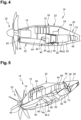
- an aircraft 10 comprises at least one wing 12 and several electric propulsion units 14 fixed under the wing 12.
- the invention is not limited to this embodiment for the positioning of the electric propulsion units 14.
- each electric propulsion unit 14 comprises at least one electric power system 16 such as a set of fuel cells for example, at least one electric motor 18 powered by the electric power system 16, a propeller 20 driven in rotation by the electric motor 18 as well as a nacelle 22 housing the electric power system 16 and the electric motor 18.
- electric power system 16 such as a set of fuel cells for example
- a propeller 20 driven in rotation by the electric motor 18 as well as a nacelle 22 housing the electric power system 16 and the electric motor 18.
- the electric motor 18 includes an output shaft A18 supporting the propeller 20.
- the propeller 20 comprises several blades P20.
- a longitudinal direction D1 is a direction parallel to the output shaft A18.
- a transverse plane is a plane perpendicular to the longitudinal direction D1.
- a vertical median plane P1 is a plane passing through the output shaft A18, vertical when the aircraft is on the ground.
- front and rear refer to the direction of the air flow around the electric propulsion unit 14 in flight, the latter flowing from front to rear.
- the electric propulsion unit 14 may include at least one auxiliary equipment 24, such as a tank for example.
- the nacelle 22 comprises a primary structure 26 supporting the electric power system 16 and the electric motor 18 as well as a secondary structure comprising a fairing 28, supported by the primary structure 26, enveloping the primary structure 26, the electric power system 16 and the electric motor 18 contributing to the aerodynamic performance of the aircraft 10.
- the fairing 28 comprises a central fairing 32 with a substantially constant cross section in the longitudinal direction D1, an approximately conical front fairing 34 which extends from the central fairing 32 to a front end 34.1 and an approximately conical rear fairing 36 which extends from the central fairing 32 to a rear end 36.1.
- the electric motor 18 is positioned in the front fairing 34 and the electric power system 16 in the central fairing 32.
- the central fairing 32 comprises two side faces 32.1, 32.2 which are substantially plane and parallel to the vertical median plane P1.
- the front end 34.1 of the front fairing 34 comprises a hole crossed by the output shaft A18.
- the electric propulsion unit 14 includes a cooling system to remove the heat produced by the electric power system 16.
- Said cooling system comprises a main cooling circuit 40 which comprises, from front to rear, a main air inlet 42, at least one intake duct 44, at least one main heat exchanger 46, at least an exhaust duct 48 and a main air outlet 50.
- Said main cooling circuit 40 is substantially symmetrical with respect to the vertical median plane P1.
- the front fairing 34 comprises a protrude 52 positioned in the lower part of the front fairing 34, said protrude 52 having a front face 54 located approximately in the same transverse plane as the front end 34.1 of the front fairing 34.
- the front face 54 is located just behind the blades P20 of the propeller 20.
- the main air inlet 42 is positioned on the front face 54, at least a part of the intake duct 44 being housed in said protrude 52.
- Positioning the main air inlet 42 just behind the propeller 20 allows air flow to be generated in the main cooling circuit 40 without the need for a fan. Additionally, this positioning does not significantly impact the aerodynamics of the electric propulsion unit 14.
- the main air inlet 42 occupies the entire front face 54.
- the main air outlet 50 is positioned just behind the central fairing 32, in the lower part of the rear fairing 36.
- the main air outlet 50 being positioning in the rear fairing 36, it is configured to eject an air flow substantially parallel to the longitudinal direction D1 generating additional thrust.
- the main air outlet 20 comprises at least a main flap 56 configured to at least partially close the main air outlet 50.
- the main flap 56 is movable between a closed position in which it completely closes the main air outlet 50 and a fully open position in which it completely clears the main air outlet 50.
- the main flap 56 can occupy different intermediate positions between the closed and fully open positions.
- the position of the main flap 56 is adjustable in order to adjust an air mass flow in the main cooling circuit 40.
- the cooling system comprises a control for controlling the position of the main flap 56.
- the main heat exchanger 46 comprises an inlet face 46.1 and an outlet face 46.2, substantially parallel to the inlet face 46.1.
- the intake duct 44 connects the main air inlet 42 and the inlet face 46.1 of the main heat exchanger 46.
- the exhaust duct 48 connects the outlet face 46.2 of the main heat exchanger 46 and the main air outlet 50.
- the inlet and outlet faces 46.1, 46.2 of the main heat exchanger 46 are not parallel to a transverse plane but inclined. According to an embodiment, the inlet and outlet faces 46.1, 46.2 of the main heat exchanger 46 form an angle greater than 30° with a transverse plane. This configuration makes it possible to increase the section of the main heat exchanger 46 and therefore the exchange surface by limiting the increase in the cross section of the central fairing 32.
- the main cooling circuit is sized for the cooling needs of the electric power system during the cruise flight. Consequently, it is undersized for the most important needs, especially during take-off.
- the sections of the main air inlet 42 and the main air outlet 50 are smaller than those of a cooling circuit of the prior art, what tends to reduce the impact on the aerodynamics of the aircraft.
- the cooling system comprises at least a secondary cooling circuit 58 which comprises, from front to rear, a secondary air inlet 60, at least one intake duct 62, at least one secondary heat exchanger 64, at least an exhaust duct 66 and a secondary air outlet 68.
- the secondary air inlet 60 is positioned on one of the side faces 32.1, 32.2 of the central fairing 32.
- the secondary air inlet 60 is flush with the outside surface of the nacelle to limit its impact on the aerodynamics of the aircraft.
- the secondary air outlet 68 is positioned in the lower part of the rear fairing 36 between the main air outlet 50 and the rear end 36.1 of the rear fairing 36.
- the secondary air outlet 68 being positioned in the rear fairing 36, it is configured to eject an air flow substantially parallel to the longitudinal direction D1, generating additional thrust.
- the secondary cooling circuit 58 comprises a fan 70, positioned in the exhaust duct 66, to regulate an air mass flow in the secondary cooling circuit 58 according to the cooling needs of the electric power system 16.
- the secondary air inlet 60 comprises a secondary flap 72 movable between a closed position, visible in the upper part of figure 3 , in which it completely closes the secondary air inlet 60 and an at least partially open position, visible in the lower part of figure 3 , in which it at least partially clears the secondary air inlet 60.
- the secondary flap 72 can occupy different intermediate positions between the closed and partially open positions.
- the position of the secondary flap 72 is adjustable in order to adjust an air mass flow in the secondary cooling circuit 58. When the secondary flap 72 is in the closed position, it greatly reduces the impact of the secondary air inlet 60 on the aerodynamics of the aircraft.
- the cooling system comprises a control for controlling the position of the secondary flap 72 which can be the same as that of the main flap 56.
- the secondary air outlet 68 comprises a movable flap 74 to close it when the secondary cooling circuit 58 is not used in order to limit the impact of said secondary air outlet 68 on the aerodynamics of the aircraft.
- the secondary cooling circuit 58 is sized to increase the cooling capacity of the main cooling circuit 40 and meet the most important cooling needs of the power supply system 16 during certain phases of flight such as take-offs.
- the cooling system comprises only one secondary cooling circuit 58.
- the cooling system comprises two secondary cooling circuits 58, 58', arranged on either side of the vertical median plane P1, approximately symmetrical with respect to this vertical median plane P1.
- the main and secondary cooling circuits 40, 58 operate simultaneously during the take-off and climb flight phases when the cooling needs are the greatest.
- the secondary cooling circuit 58 is deactivated, the secondary flaps 72 being in the closed position during the cruising and descent flight phases. Only the main cooling circuit 40, sized for these phases of flight, operates.
- the invention makes it possible to optimize the cooling capacity according to the cooling needs, what contributes to reduce the drag during certain phases of flight such as the cruising phase.
- Optimizing the cooling capacity makes it possible to reduce the section of the nacelle and thus to optimize the thrust of the propeller 20.
Landscapes
- Engineering & Computer Science (AREA)
- Aviation & Aerospace Engineering (AREA)
- Mechanical Engineering (AREA)
- Chemical & Material Sciences (AREA)
- Combustion & Propulsion (AREA)
- Motor Or Generator Cooling System (AREA)
Claims (11)
- Elektrische Antriebseinheit eines Luftfahrzeugs mit:- wenigstens einem elektrischen Energiesystem (16),- wenigstens einem Elektromotor (18) mit einer Abtriebswelle (A18), der von dem elektrischen Energiesystem (16) angetrieben ist,- einem Propeller (20), der durch den Elektromotor (18) in Drehung versetzt ist,- einem Kühlsystem für das elektrische Energiesystem (16) mit einem Hauptkühlkreislauf (40), der umfasst:o einen Hauptlufteinlass (42),o wenigstens einen Ansaugkanal (44),o wenigstens einen Hauptwärmetauscher (46),o wenigstens einen Abluftkanal (48),o einen Hauptluftauslass (50),- einer Gondel (22), in der das elektrische Energiesystem (16) und der Elektromotor (18) untergebracht sind und die umfasst:wobei die vordere Verkleidung (34) einen Vorsprung (52) aufweist, der in einem unteren Teil der vorderen Verkleidung (34) angeordnet ist, wobei der Vorsprung (52) eine vordere Fläche (54) aufweist, die in einer zur Abtriebswelle (A18) rechtwinkligen Querebene angeordnet ist, wobei der Hauptlufteinlass (42) an der vorderen Fläche (54) angeordnet ist, wobei der Hauptkühlkreislauf (40) für den Kühlbedarf des elektrischen Energiesystems (16) während des Reisefluges ausgelegt ist und wobei das Kühlsystem wenigstens einen sekundären Kühlkreislauf (58) aufweist, der einen sekundären Lufteinlass (60), wenigstens einen Einlasskanal (62), wenigstens einen sekundären Wärmetauscher (64), wenigstens einen Auslasskanal (66) und einen sekundären Luftauslass (66) umfasst, wobei der wenigstens eine sekundäre Kühlkreislauf (58) so ausgelegt ist, dass er die Kühlkapazität des Hauptkühlkreislaufs (40) erhöht.o eine zentrale Verkleidung (32),o eine vordere Verkleidung (34), die sich von der zentralen Verkleidung (32) zu einem vorderen Ende (34.1) erstreckt, undo eine hintere Verkleidung (36), die sich von der mittleren Verkleidung (32) zu einem hinteren Ende (36.1) erstreckt,
- Elektrische Antriebseinheit nach Anspruch 1, wobei die vordere Fläche (54) in derselben Querebene liegt wie das vordere Ende (34.1) der vorderen Verkleidung (34).
- Elektrische Antriebseinheit nach einem der vorhergehenden Ansprüche, wobei der Hauptlufteinlass (42) die gesamte vordere Fläche (54) einnimmt.
- Elektrische Antriebseinheit nach einem der vorhergehenden Ansprüche, wobei der Hauptluftauslass (50) an der hinteren Verkleidung (36) angeordnet und so eingerichtet ist, dass er einen Luftstrom ausstößt, der einen zusätzlichen Schub erzeugt.
- Elektrische Antriebseinheit nach einem der vorhergehenden Ansprüche, wobei der Hauptluftauslass (50) wenigstens eine Hauptklappe (56) aufweist, die verstellbar ist, um einen Luftmassenstrom im Hauptkühlkreislauf (40) einzustellen.
- Elektrische Antriebseinheit nach einem der vorhergehenden Ansprüche, wobei der Hauptwärmetauscher (46) eine mit dem Einlasskanal (44) verbundene Einlassfläche (46.1) und eine im Wesentlichen parallel zur Einlassfläche (46.1) verlaufende, mit dem Auslasskanal (48) verbundene Auslassfläche (46.2) aufweist, wobei die Einlass- und Auslassflächen (46.1, 46.2) des Hauptwärmetauschers (46) in Bezug auf eine zur Abtriebswelle (A18) rechtwinklige Querebene geneigt sind.
- Elektrische Antriebseinheit nach einem der vorhergehenden Ansprüche, wobei die zentrale Verkleidung (32) zwei Seitenflächen (32.1, 32.2) aufweist und wobei der sekundäre Lufteinlass (60) an einer der Seitenflächen (32.1, 32.2) der zentralen Verkleidung (32) angeordnet ist, wobei der sekundäre Lufteinlass (60) vorzugsweise bündig ausgebildet ist.
- Elektrische Antriebseinheit nach einem der vorhergehenden Ansprüche, wobei der sekundäre Lufteinlass (60) eine Sekundärklappe (72) aufweist, die zwischen einer geschlossenen Stellung, in der die Sekundärklappe (72) den sekundären Lufteinlass (60) vollständig verschließt, und einer zumindest teilweise geöffneten Stellung, in der die Sekundärklappe (72) den sekundären Lufteinlass (60) zumindest teilweise freigibt, beweglich ist.
- Elektrische Antriebseinheit nach einem der vorhergehenden Ansprüche, wobei der sekundäre Kühlkreislauf (58) ein Gebläse (70) zur Regelung eines Luftmassenstroms im sekundären Kühlkreislauf (58) aufweist.
- Elektrische Antriebseinheit nach einem der vorhergehenden Ansprüche, wobei der sekundäre Luftauslass (68) an einem unteren Teil der hinteren Verkleidung (36) zwischen dem Hauptluftauslass (50) und dem hinteren Ende (36.1) der hinteren Verkleidung (36) angeordnet ist und so eingerichtet ist, dass er einen Luftstrom ausstößt, der einen zusätzlichen Schub erzeugt.
- Luftfahrzeug mit wenigstens einer elektrischen Antriebseinheit nach einem der vorhergehenden Ansprüche.
Priority Applications (2)
| Application Number | Priority Date | Filing Date | Title |
|---|---|---|---|
| EP21172646.8A EP4086176B1 (de) | 2021-05-07 | 2021-05-07 | Elektrische antriebseinheit eines flugzeugs mit einem kühlsystem mit mindestens einem frontlufteinlass und flugzeug mit mindestens einer solchen elektrischen antriebseinheit |
| US17/737,134 US11952134B2 (en) | 2021-05-07 | 2022-05-05 | Electric propulsion unit of an aircraft comprising a cooling system incorporating at least one front air inlet and aircraft comprising at least one such electric propulsion unit |
Applications Claiming Priority (1)
| Application Number | Priority Date | Filing Date | Title |
|---|---|---|---|
| EP21172646.8A EP4086176B1 (de) | 2021-05-07 | 2021-05-07 | Elektrische antriebseinheit eines flugzeugs mit einem kühlsystem mit mindestens einem frontlufteinlass und flugzeug mit mindestens einer solchen elektrischen antriebseinheit |
Publications (2)
| Publication Number | Publication Date |
|---|---|
| EP4086176A1 EP4086176A1 (de) | 2022-11-09 |
| EP4086176B1 true EP4086176B1 (de) | 2025-03-05 |
Family
ID=75870399
Family Applications (1)
| Application Number | Title | Priority Date | Filing Date |
|---|---|---|---|
| EP21172646.8A Active EP4086176B1 (de) | 2021-05-07 | 2021-05-07 | Elektrische antriebseinheit eines flugzeugs mit einem kühlsystem mit mindestens einem frontlufteinlass und flugzeug mit mindestens einer solchen elektrischen antriebseinheit |
Country Status (2)
| Country | Link |
|---|---|
| US (1) | US11952134B2 (de) |
| EP (1) | EP4086176B1 (de) |
Families Citing this family (13)
| Publication number | Priority date | Publication date | Assignee | Title |
|---|---|---|---|---|
| US12054266B2 (en) * | 2021-03-29 | 2024-08-06 | Aurora Flight Sciences Corporation | Integrated electric nacelle system and method |
| CN115750439B (zh) * | 2022-11-16 | 2023-06-16 | 南昌航空大学 | 一种基于边界层摄入的风冷一体化涵道风扇 |
| KR102827094B1 (ko) * | 2022-12-08 | 2025-07-01 | 한국항공우주연구원 | 양방향 냉각 유로를 갖는 틸트로터 항공기 |
| US12240615B2 (en) * | 2022-12-12 | 2025-03-04 | General Electric Company | Electric propulsor with electric machine in thermal communication with a heat exchanger |
| DE102023106282A1 (de) * | 2023-03-14 | 2024-09-19 | Rolls-Royce Deutschland Ltd & Co Kg | Antriebseinheit für ein Luftfahrzeug mit Haupt- und Hilfskühlsystem |
| US20250058889A1 (en) * | 2023-08-14 | 2025-02-20 | The Boeing Company | Configuration for a LH2 Fuel Cell Aircraft with Distributed Systems |
| US12497188B2 (en) | 2023-08-14 | 2025-12-16 | The Boeing Company | Liquid hydrogen feed system for fuel cell powered aircraft |
| US20250059933A1 (en) * | 2023-08-14 | 2025-02-20 | The Boeing Company | Method of Nacelle Air Heat Exchanger Integration for a Hydrogen Fueled Fuel Cell Powered Aircraft |
| GB2634207A (en) * | 2023-09-26 | 2025-04-09 | Gkn Aerospace Services Ltd | Apparatus |
| USD1080503S1 (en) * | 2023-12-29 | 2025-06-24 | Aerojones Aviation Technology Co., Ltd. | Front shell for an aircraft |
| FR3158953A1 (fr) | 2024-02-05 | 2025-08-08 | Airbus Operations | Ensemble propulsif pour aéronef comportant un ventilateur d’extraction |
| FR3161418B1 (fr) * | 2024-04-17 | 2026-03-13 | Safran | Procede de controle d’un groupe propulsif d’aeronef |
| FR3161417B1 (fr) * | 2024-04-17 | 2026-04-03 | Safran | Groupe propulsif d’aeronef comprenant une pile a combustible |
Family Cites Families (15)
| Publication number | Priority date | Publication date | Assignee | Title |
|---|---|---|---|---|
| US2543112A (en) * | 1946-07-05 | 1951-02-27 | Bendix Aviat Corp | Cowl flap control for aircraft |
| US5284012A (en) * | 1991-05-16 | 1994-02-08 | General Electric Company | Nacelle cooling and ventilation system |
| US7434765B2 (en) * | 2005-02-16 | 2008-10-14 | The Boeing Company | Heat exchanger systems and associated systems and methods for cooling aircraft starter/generators |
| DE102012217469A1 (de) * | 2012-09-26 | 2014-03-27 | Siemens Aktiengesellschaft | Kühlsystem für Komponenten in (Luft-)Fahrzeugstrukturen |
| FR3018503B1 (fr) * | 2014-03-13 | 2017-10-13 | Snecma | Nacelle comprenant un echangeur pour refroidir un flux d'air |
| US10240522B2 (en) * | 2015-08-07 | 2019-03-26 | Pratt & Whitney Canada Corp. | Auxiliary power unit with combined cooling of generator |
| WO2018042703A1 (ja) * | 2016-09-01 | 2018-03-08 | 株式会社Ihi | 航空機搭載発電機の排熱システム |
| US10850841B2 (en) * | 2018-06-20 | 2020-12-01 | Intel Corporation | Unmanned aerial vehicle and method for operating an unmanned aerial vehicle |
| GB201811040D0 (en) | 2018-07-05 | 2018-08-22 | Rolls Royce Plc | Cooling |
| US11628942B2 (en) * | 2019-03-01 | 2023-04-18 | Pratt & Whitney Canada Corp. | Torque ripple control for an aircraft power train |
| US11427344B2 (en) * | 2019-03-01 | 2022-08-30 | Pratt & Whitney Canada Corp. | Cooling system configurations for an aircraft having hybrid-electric propulsion system |
| GB2587669A (en) * | 2019-10-02 | 2021-04-07 | Advanced Mobility Res And Development Ltd | Systems and methods for aircraft |
| US11603800B2 (en) * | 2019-12-03 | 2023-03-14 | Rohr, Inc. | Firewall assemblies for hybrid electric aircraft powerplants |
| JP2022053627A (ja) * | 2020-09-25 | 2022-04-06 | 本田技研工業株式会社 | 推進システム |
| US12054266B2 (en) * | 2021-03-29 | 2024-08-06 | Aurora Flight Sciences Corporation | Integrated electric nacelle system and method |
-
2021
- 2021-05-07 EP EP21172646.8A patent/EP4086176B1/de active Active
-
2022
- 2022-05-05 US US17/737,134 patent/US11952134B2/en active Active
Also Published As
| Publication number | Publication date |
|---|---|
| US20220355943A1 (en) | 2022-11-10 |
| EP4086176A1 (de) | 2022-11-09 |
| US11952134B2 (en) | 2024-04-09 |
Similar Documents
| Publication | Publication Date | Title |
|---|---|---|
| EP4086176B1 (de) | Elektrische antriebseinheit eines flugzeugs mit einem kühlsystem mit mindestens einem frontlufteinlass und flugzeug mit mindestens einer solchen elektrischen antriebseinheit | |
| US7188802B2 (en) | Convertible aircraft provided with two tilt fans on either side of the fuselage, and with a non-tilting fan inserted in the fuselage | |
| US20050223694A1 (en) | Ducted air power plant | |
| US5996935A (en) | Power plants | |
| US5012646A (en) | Turbine engine having combustor air precooler | |
| US11472560B2 (en) | System for an aircraft | |
| EP3323730A1 (de) | Flugzeug mit winkelmontiertem turboproptriebwerk | |
| JP2008518828A (ja) | 高揚力の分散型アクティブフローコントロールシステムおよび方法 | |
| EP1141522A2 (de) | Ummanteltes stauluftturbine-generator-system und dessen kühlung | |
| US12172750B2 (en) | Engine comprising a movable aerodynamic component | |
| EP2272758B1 (de) | Klappe für einen Staulufteinlass | |
| CN114508423A (zh) | 燃气涡轮发动机 | |
| US7364118B2 (en) | Propulsion arrangement | |
| US3212731A (en) | Fan powered aircraft | |
| CA2605518A1 (en) | Engine propulsion system and methods of assembling the same | |
| US12545400B2 (en) | Parallel and series multi-stage electric fan | |
| EP2564051B1 (de) | Flugzeug-turbofan-triebwerk | |
| KR20050016643A (ko) | 덕트형 공기 동력 장치 | |
| US12503219B2 (en) | Aeronautical propulsion system having electric fans | |
| US11867135B1 (en) | Vectoring exhaust nozzle for an aircraft powerplant | |
| JP7372225B2 (ja) | ガスタービン発電機 | |
| RU2332332C2 (ru) | Самолет с вертикальными взлетом и посадкой | |
| EP4387893A1 (de) | System zum heben, antreiben und steuern eines luftfahrzeugs | |
| Nichols | Dual cycle aircraft turbine engine |
Legal Events
| Date | Code | Title | Description |
|---|---|---|---|
| PUAI | Public reference made under article 153(3) epc to a published international application that has entered the european phase |
Free format text: ORIGINAL CODE: 0009012 |
|
| STAA | Information on the status of an ep patent application or granted ep patent |
Free format text: STATUS: THE APPLICATION HAS BEEN PUBLISHED |
|
| AK | Designated contracting states |
Kind code of ref document: A1 Designated state(s): AL AT BE BG CH CY CZ DE DK EE ES FI FR GB GR HR HU IE IS IT LI LT LU LV MC MK MT NL NO PL PT RO RS SE SI SK SM TR |
|
| STAA | Information on the status of an ep patent application or granted ep patent |
Free format text: STATUS: REQUEST FOR EXAMINATION WAS MADE |
|
| 17P | Request for examination filed |
Effective date: 20230427 |
|
| RBV | Designated contracting states (corrected) |
Designated state(s): AL AT BE BG CH CY CZ DE DK EE ES FI FR GB GR HR HU IE IS IT LI LT LU LV MC MK MT NL NO PL PT RO RS SE SI SK SM TR |
|
| REG | Reference to a national code |
Ref country code: DE Ref legal event code: R079 Free format text: PREVIOUS MAIN CLASS: B64D0027240000 Ipc: B64D0033100000 Ref document number: 602021027014 Country of ref document: DE |
|
| GRAP | Despatch of communication of intention to grant a patent |
Free format text: ORIGINAL CODE: EPIDOSNIGR1 |
|
| STAA | Information on the status of an ep patent application or granted ep patent |
Free format text: STATUS: GRANT OF PATENT IS INTENDED |
|
| RIC1 | Information provided on ipc code assigned before grant |
Ipc: B64D 29/00 20060101ALI20240909BHEP Ipc: B64D 27/24 20060101ALI20240909BHEP Ipc: B64D 33/10 20060101AFI20240909BHEP |
|
| INTG | Intention to grant announced |
Effective date: 20241011 |
|
| GRAS | Grant fee paid |
Free format text: ORIGINAL CODE: EPIDOSNIGR3 |
|
| GRAA | (expected) grant |
Free format text: ORIGINAL CODE: 0009210 |
|
| STAA | Information on the status of an ep patent application or granted ep patent |
Free format text: STATUS: THE PATENT HAS BEEN GRANTED |
|
| AK | Designated contracting states |
Kind code of ref document: B1 Designated state(s): AL AT BE BG CH CY CZ DE DK EE ES FI FR GB GR HR HU IE IS IT LI LT LU LV MC MK MT NL NO PL PT RO RS SE SI SK SM TR |
|
| REG | Reference to a national code |
Ref country code: GB Ref legal event code: FG4D |
|
| REG | Reference to a national code |
Ref country code: CH Ref legal event code: EP |
|
| REG | Reference to a national code |
Ref country code: DE Ref legal event code: R096 Ref document number: 602021027014 Country of ref document: DE |
|
| REG | Reference to a national code |
Ref country code: IE Ref legal event code: FG4D |
|
| PG25 | Lapsed in a contracting state [announced via postgrant information from national office to epo] |
Ref country code: RS Free format text: LAPSE BECAUSE OF FAILURE TO SUBMIT A TRANSLATION OF THE DESCRIPTION OR TO PAY THE FEE WITHIN THE PRESCRIBED TIME-LIMIT Effective date: 20250605 |
|
| PG25 | Lapsed in a contracting state [announced via postgrant information from national office to epo] |
Ref country code: FI Free format text: LAPSE BECAUSE OF FAILURE TO SUBMIT A TRANSLATION OF THE DESCRIPTION OR TO PAY THE FEE WITHIN THE PRESCRIBED TIME-LIMIT Effective date: 20250305 |
|
| PGFP | Annual fee paid to national office [announced via postgrant information from national office to epo] |
Ref country code: DE Payment date: 20250521 Year of fee payment: 5 |
|
| REG | Reference to a national code |
Ref country code: NL Ref legal event code: MP Effective date: 20250305 |
|
| PG25 | Lapsed in a contracting state [announced via postgrant information from national office to epo] |
Ref country code: ES Free format text: LAPSE BECAUSE OF FAILURE TO SUBMIT A TRANSLATION OF THE DESCRIPTION OR TO PAY THE FEE WITHIN THE PRESCRIBED TIME-LIMIT Effective date: 20250305 |
|
| PGFP | Annual fee paid to national office [announced via postgrant information from national office to epo] |
Ref country code: GB Payment date: 20250527 Year of fee payment: 5 |
|
| REG | Reference to a national code |
Ref country code: LT Ref legal event code: MG9D |
|
| PG25 | Lapsed in a contracting state [announced via postgrant information from national office to epo] |
Ref country code: NO Free format text: LAPSE BECAUSE OF FAILURE TO SUBMIT A TRANSLATION OF THE DESCRIPTION OR TO PAY THE FEE WITHIN THE PRESCRIBED TIME-LIMIT Effective date: 20250605 |
|
| PG25 | Lapsed in a contracting state [announced via postgrant information from national office to epo] |
Ref country code: HR Free format text: LAPSE BECAUSE OF FAILURE TO SUBMIT A TRANSLATION OF THE DESCRIPTION OR TO PAY THE FEE WITHIN THE PRESCRIBED TIME-LIMIT Effective date: 20250305 |
|
| PG25 | Lapsed in a contracting state [announced via postgrant information from national office to epo] |
Ref country code: LV Free format text: LAPSE BECAUSE OF FAILURE TO SUBMIT A TRANSLATION OF THE DESCRIPTION OR TO PAY THE FEE WITHIN THE PRESCRIBED TIME-LIMIT Effective date: 20250305 |
|
| PGFP | Annual fee paid to national office [announced via postgrant information from national office to epo] |
Ref country code: FR Payment date: 20250528 Year of fee payment: 5 |
|
| PG25 | Lapsed in a contracting state [announced via postgrant information from national office to epo] |
Ref country code: BG Free format text: LAPSE BECAUSE OF FAILURE TO SUBMIT A TRANSLATION OF THE DESCRIPTION OR TO PAY THE FEE WITHIN THE PRESCRIBED TIME-LIMIT Effective date: 20250305 Ref country code: GR Free format text: LAPSE BECAUSE OF FAILURE TO SUBMIT A TRANSLATION OF THE DESCRIPTION OR TO PAY THE FEE WITHIN THE PRESCRIBED TIME-LIMIT Effective date: 20250606 |
|
| REG | Reference to a national code |
Ref country code: AT Ref legal event code: MK05 Ref document number: 1772768 Country of ref document: AT Kind code of ref document: T Effective date: 20250305 |
|
| PG25 | Lapsed in a contracting state [announced via postgrant information from national office to epo] |
Ref country code: NL Free format text: LAPSE BECAUSE OF FAILURE TO SUBMIT A TRANSLATION OF THE DESCRIPTION OR TO PAY THE FEE WITHIN THE PRESCRIBED TIME-LIMIT Effective date: 20250305 |
|
| PG25 | Lapsed in a contracting state [announced via postgrant information from national office to epo] |
Ref country code: SE Free format text: LAPSE BECAUSE OF FAILURE TO SUBMIT A TRANSLATION OF THE DESCRIPTION OR TO PAY THE FEE WITHIN THE PRESCRIBED TIME-LIMIT Effective date: 20250305 |
|
| PG25 | Lapsed in a contracting state [announced via postgrant information from national office to epo] |
Ref country code: SM Free format text: LAPSE BECAUSE OF FAILURE TO SUBMIT A TRANSLATION OF THE DESCRIPTION OR TO PAY THE FEE WITHIN THE PRESCRIBED TIME-LIMIT Effective date: 20250305 |
|
| PG25 | Lapsed in a contracting state [announced via postgrant information from national office to epo] |
Ref country code: PT Free format text: LAPSE BECAUSE OF FAILURE TO SUBMIT A TRANSLATION OF THE DESCRIPTION OR TO PAY THE FEE WITHIN THE PRESCRIBED TIME-LIMIT Effective date: 20250707 |
|
| PG25 | Lapsed in a contracting state [announced via postgrant information from national office to epo] |
Ref country code: IT Free format text: LAPSE BECAUSE OF FAILURE TO SUBMIT A TRANSLATION OF THE DESCRIPTION OR TO PAY THE FEE WITHIN THE PRESCRIBED TIME-LIMIT Effective date: 20250305 Ref country code: PL Free format text: LAPSE BECAUSE OF FAILURE TO SUBMIT A TRANSLATION OF THE DESCRIPTION OR TO PAY THE FEE WITHIN THE PRESCRIBED TIME-LIMIT Effective date: 20250305 |
|
| PG25 | Lapsed in a contracting state [announced via postgrant information from national office to epo] |
Ref country code: AT Free format text: LAPSE BECAUSE OF FAILURE TO SUBMIT A TRANSLATION OF THE DESCRIPTION OR TO PAY THE FEE WITHIN THE PRESCRIBED TIME-LIMIT Effective date: 20250305 |
|
| PG25 | Lapsed in a contracting state [announced via postgrant information from national office to epo] |
Ref country code: CZ Free format text: LAPSE BECAUSE OF FAILURE TO SUBMIT A TRANSLATION OF THE DESCRIPTION OR TO PAY THE FEE WITHIN THE PRESCRIBED TIME-LIMIT Effective date: 20250305 Ref country code: EE Free format text: LAPSE BECAUSE OF FAILURE TO SUBMIT A TRANSLATION OF THE DESCRIPTION OR TO PAY THE FEE WITHIN THE PRESCRIBED TIME-LIMIT Effective date: 20250305 |
|
| PG25 | Lapsed in a contracting state [announced via postgrant information from national office to epo] |
Ref country code: RO Free format text: LAPSE BECAUSE OF FAILURE TO SUBMIT A TRANSLATION OF THE DESCRIPTION OR TO PAY THE FEE WITHIN THE PRESCRIBED TIME-LIMIT Effective date: 20250305 |
|
| PG25 | Lapsed in a contracting state [announced via postgrant information from national office to epo] |
Ref country code: SK Free format text: LAPSE BECAUSE OF FAILURE TO SUBMIT A TRANSLATION OF THE DESCRIPTION OR TO PAY THE FEE WITHIN THE PRESCRIBED TIME-LIMIT Effective date: 20250305 |
|
| PG25 | Lapsed in a contracting state [announced via postgrant information from national office to epo] |
Ref country code: IS Free format text: LAPSE BECAUSE OF FAILURE TO SUBMIT A TRANSLATION OF THE DESCRIPTION OR TO PAY THE FEE WITHIN THE PRESCRIBED TIME-LIMIT Effective date: 20250705 |
|
| REG | Reference to a national code |
Ref country code: DE Ref legal event code: R097 Ref document number: 602021027014 Country of ref document: DE |
|
| REG | Reference to a national code |
Ref country code: CH Ref legal event code: H13 Free format text: ST27 STATUS EVENT CODE: U-0-0-H10-H13 (AS PROVIDED BY THE NATIONAL OFFICE) Effective date: 20251223 |
|
| PLBE | No opposition filed within time limit |
Free format text: ORIGINAL CODE: 0009261 |
|
| STAA | Information on the status of an ep patent application or granted ep patent |
Free format text: STATUS: NO OPPOSITION FILED WITHIN TIME LIMIT |
|
| PG25 | Lapsed in a contracting state [announced via postgrant information from national office to epo] |
Ref country code: DK Free format text: LAPSE BECAUSE OF FAILURE TO SUBMIT A TRANSLATION OF THE DESCRIPTION OR TO PAY THE FEE WITHIN THE PRESCRIBED TIME-LIMIT Effective date: 20250305 |
|
| REG | Reference to a national code |
Ref country code: CH Ref legal event code: L10 Free format text: ST27 STATUS EVENT CODE: U-0-0-L10-L00 (AS PROVIDED BY THE NATIONAL OFFICE) Effective date: 20260114 |
|
| PG25 | Lapsed in a contracting state [announced via postgrant information from national office to epo] |
Ref country code: LU Free format text: LAPSE BECAUSE OF NON-PAYMENT OF DUE FEES Effective date: 20250507 |
|
| PG25 | Lapsed in a contracting state [announced via postgrant information from national office to epo] |
Ref country code: CH Free format text: LAPSE BECAUSE OF NON-PAYMENT OF DUE FEES Effective date: 20250531 |
|
| REG | Reference to a national code |
Ref country code: BE Ref legal event code: MM Effective date: 20250531 |
|
| PG25 | Lapsed in a contracting state [announced via postgrant information from national office to epo] |
Ref country code: MC Free format text: LAPSE BECAUSE OF FAILURE TO SUBMIT A TRANSLATION OF THE DESCRIPTION OR TO PAY THE FEE WITHIN THE PRESCRIBED TIME-LIMIT Effective date: 20250305 |
|
| 26N | No opposition filed |
Effective date: 20251208 |
|
| PG25 | Lapsed in a contracting state [announced via postgrant information from national office to epo] |
Ref country code: IE Free format text: LAPSE BECAUSE OF NON-PAYMENT OF DUE FEES Effective date: 20250507 |
|
| PG25 | Lapsed in a contracting state [announced via postgrant information from national office to epo] |
Ref country code: BE Free format text: LAPSE BECAUSE OF NON-PAYMENT OF DUE FEES Effective date: 20250531 |