EP4086151A1 - Oscillation system of the swingarm of a wheel with respect to the frame of a vehicle - Google Patents
Oscillation system of the swingarm of a wheel with respect to the frame of a vehicle Download PDFInfo
- Publication number
- EP4086151A1 EP4086151A1 EP22166849.4A EP22166849A EP4086151A1 EP 4086151 A1 EP4086151 A1 EP 4086151A1 EP 22166849 A EP22166849 A EP 22166849A EP 4086151 A1 EP4086151 A1 EP 4086151A1
- Authority
- EP
- European Patent Office
- Prior art keywords
- chamber
- crank
- dividing wall
- connecting rod
- cylinder
- Prior art date
- Legal status (The legal status is an assumption and is not a legal conclusion. Google has not performed a legal analysis and makes no representation as to the accuracy of the status listed.)
- Granted
Links
Images


Classifications
-
- B—PERFORMING OPERATIONS; TRANSPORTING
- B62—LAND VEHICLES FOR TRAVELLING OTHERWISE THAN ON RAILS
- B62K—CYCLES; CYCLE FRAMES; CYCLE STEERING DEVICES; RIDER-OPERATED TERMINAL CONTROLS SPECIALLY ADAPTED FOR CYCLES; CYCLE AXLE SUSPENSIONS; CYCLE SIDECARS, FORECARS, OR THE LIKE
- B62K25/00—Axle suspensions
- B62K25/04—Axle suspensions for mounting axles resiliently on cycle frame or fork
- B62K25/28—Axle suspensions for mounting axles resiliently on cycle frame or fork with pivoted chain-stay
- B62K25/286—Axle suspensions for mounting axles resiliently on cycle frame or fork with pivoted chain-stay the shock absorber being connected to the chain-stay via a linkage mechanism
-
- B—PERFORMING OPERATIONS; TRANSPORTING
- B60—VEHICLES IN GENERAL
- B60G—VEHICLE SUSPENSION ARRANGEMENTS
- B60G11/00—Resilient suspensions characterised by arrangement, location or kind of springs
- B60G11/26—Resilient suspensions characterised by arrangement, location or kind of springs having fluid springs only, e.g. hydropneumatic springs
- B60G11/265—Resilient suspensions characterised by arrangement, location or kind of springs having fluid springs only, e.g. hydropneumatic springs hydraulic springs
-
- B—PERFORMING OPERATIONS; TRANSPORTING
- B60—VEHICLES IN GENERAL
- B60G—VEHICLE SUSPENSION ARRANGEMENTS
- B60G11/00—Resilient suspensions characterised by arrangement, location or kind of springs
- B60G11/32—Resilient suspensions characterised by arrangement, location or kind of springs having springs of different kinds
- B60G11/48—Resilient suspensions characterised by arrangement, location or kind of springs having springs of different kinds not including leaf springs
- B60G11/56—Resilient suspensions characterised by arrangement, location or kind of springs having springs of different kinds not including leaf springs having helical, spiral or coil springs, and also fluid springs
-
- B—PERFORMING OPERATIONS; TRANSPORTING
- B60—VEHICLES IN GENERAL
- B60G—VEHICLE SUSPENSION ARRANGEMENTS
- B60G15/00—Resilient suspensions characterised by arrangement, location or type of combined spring and vibration damper, e.g. telescopic type
- B60G15/08—Resilient suspensions characterised by arrangement, location or type of combined spring and vibration damper, e.g. telescopic type having fluid spring
- B60G15/12—Resilient suspensions characterised by arrangement, location or type of combined spring and vibration damper, e.g. telescopic type having fluid spring and fluid damper
-
- B—PERFORMING OPERATIONS; TRANSPORTING
- B60—VEHICLES IN GENERAL
- B60G—VEHICLE SUSPENSION ARRANGEMENTS
- B60G17/00—Resilient suspensions having means for adjusting the spring or vibration-damper characteristics, for regulating the distance between a supporting surface and a sprung part of vehicle or for locking suspension during use to meet varying vehicular or surface conditions, e.g. due to speed or load
- B60G17/02—Spring characteristics, e.g. mechanical springs and mechanical adjusting means
- B60G17/04—Spring characteristics, e.g. mechanical springs and mechanical adjusting means fluid spring characteristics
-
- B—PERFORMING OPERATIONS; TRANSPORTING
- B60—VEHICLES IN GENERAL
- B60G—VEHICLE SUSPENSION ARRANGEMENTS
- B60G3/00—Resilient suspensions for a single wheel
- B60G3/02—Resilient suspensions for a single wheel with a single pivoted arm
- B60G3/12—Resilient suspensions for a single wheel with a single pivoted arm the arm being essentially parallel to the longitudinal axis of the vehicle
- B60G3/14—Resilient suspensions for a single wheel with a single pivoted arm the arm being essentially parallel to the longitudinal axis of the vehicle the arm being rigid
-
- B—PERFORMING OPERATIONS; TRANSPORTING
- B60—VEHICLES IN GENERAL
- B60G—VEHICLE SUSPENSION ARRANGEMENTS
- B60G3/00—Resilient suspensions for a single wheel
- B60G3/18—Resilient suspensions for a single wheel with two or more pivoted arms, e.g. parallelogram
- B60G3/20—Resilient suspensions for a single wheel with two or more pivoted arms, e.g. parallelogram all arms being rigid
- B60G3/207—Resilient suspensions for a single wheel with two or more pivoted arms, e.g. parallelogram all arms being rigid the arms being essentially parallel to the longitudinal axis of the vehicle
-
- B—PERFORMING OPERATIONS; TRANSPORTING
- B62—LAND VEHICLES FOR TRAVELLING OTHERWISE THAN ON RAILS
- B62K—CYCLES; CYCLE FRAMES; CYCLE STEERING DEVICES; RIDER-OPERATED TERMINAL CONTROLS SPECIALLY ADAPTED FOR CYCLES; CYCLE AXLE SUSPENSIONS; CYCLE SIDECARS, FORECARS, OR THE LIKE
- B62K25/00—Axle suspensions
- B62K25/04—Axle suspensions for mounting axles resiliently on cycle frame or fork
- B62K25/28—Axle suspensions for mounting axles resiliently on cycle frame or fork with pivoted chain-stay
- B62K25/283—Axle suspensions for mounting axles resiliently on cycle frame or fork with pivoted chain-stay for cycles without a pedal crank, e.g. motorcycles
-
- F—MECHANICAL ENGINEERING; LIGHTING; HEATING; WEAPONS; BLASTING
- F16—ENGINEERING ELEMENTS AND UNITS; GENERAL MEASURES FOR PRODUCING AND MAINTAINING EFFECTIVE FUNCTIONING OF MACHINES OR INSTALLATIONS; THERMAL INSULATION IN GENERAL
- F16F—SPRINGS; SHOCK-ABSORBERS; MEANS FOR DAMPING VIBRATION
- F16F9/00—Springs, vibration-dampers, shock-absorbers, or similarly-constructed movement-dampers using a fluid or the equivalent as damping medium
- F16F9/06—Springs, vibration-dampers, shock-absorbers, or similarly-constructed movement-dampers using a fluid or the equivalent as damping medium using both gas and liquid
- F16F9/063—Springs, vibration-dampers, shock-absorbers, or similarly-constructed movement-dampers using a fluid or the equivalent as damping medium using both gas and liquid comprising a hollow piston rod
-
- B—PERFORMING OPERATIONS; TRANSPORTING
- B60—VEHICLES IN GENERAL
- B60G—VEHICLE SUSPENSION ARRANGEMENTS
- B60G2200/00—Indexing codes relating to suspension types
- B60G2200/10—Independent suspensions
- B60G2200/13—Independent suspensions with longitudinal arms only
-
- B—PERFORMING OPERATIONS; TRANSPORTING
- B60—VEHICLES IN GENERAL
- B60G—VEHICLE SUSPENSION ARRANGEMENTS
- B60G2200/00—Indexing codes relating to suspension types
- B60G2200/10—Independent suspensions
- B60G2200/13—Independent suspensions with longitudinal arms only
- B60G2200/132—Independent suspensions with longitudinal arms only with a single trailing arm
-
- B—PERFORMING OPERATIONS; TRANSPORTING
- B60—VEHICLES IN GENERAL
- B60G—VEHICLE SUSPENSION ARRANGEMENTS
- B60G2202/00—Indexing codes relating to the type of spring, damper or actuator
- B60G2202/10—Type of spring
- B60G2202/15—Fluid spring
- B60G2202/154—Fluid spring with an accumulator
-
- B—PERFORMING OPERATIONS; TRANSPORTING
- B60—VEHICLES IN GENERAL
- B60G—VEHICLE SUSPENSION ARRANGEMENTS
- B60G2202/00—Indexing codes relating to the type of spring, damper or actuator
- B60G2202/30—Spring/Damper and/or actuator Units
-
- B—PERFORMING OPERATIONS; TRANSPORTING
- B60—VEHICLES IN GENERAL
- B60G—VEHICLE SUSPENSION ARRANGEMENTS
- B60G2202/00—Indexing codes relating to the type of spring, damper or actuator
- B60G2202/40—Type of actuator
- B60G2202/41—Fluid actuator
- B60G2202/416—Fluid actuator using a pump, e.g. in the line connecting the lower chamber to the upper chamber of the actuator
-
- B—PERFORMING OPERATIONS; TRANSPORTING
- B60—VEHICLES IN GENERAL
- B60G—VEHICLE SUSPENSION ARRANGEMENTS
- B60G2204/00—Indexing codes related to suspensions per se or to auxiliary parts
- B60G2204/40—Auxiliary suspension parts; Adjustment of suspensions
- B60G2204/421—Pivoted lever mechanisms for mounting suspension elements, e.g. Watt linkage
-
- B—PERFORMING OPERATIONS; TRANSPORTING
- B60—VEHICLES IN GENERAL
- B60G—VEHICLE SUSPENSION ARRANGEMENTS
- B60G2300/00—Indexing codes relating to the type of vehicle
- B60G2300/12—Cycles; Motorcycles
-
- B—PERFORMING OPERATIONS; TRANSPORTING
- B60—VEHICLES IN GENERAL
- B60G—VEHICLE SUSPENSION ARRANGEMENTS
- B60G2500/00—Indexing codes relating to the regulated action or device
- B60G2500/20—Spring action or springs
- B60G2500/206—Variable pressure accumulators for hydropneumatic suspensions
- B60G2500/2062—Variable pressure accumulators for hydropneumatic suspensions by varying the air-pressure of the accumulator
-
- B—PERFORMING OPERATIONS; TRANSPORTING
- B60—VEHICLES IN GENERAL
- B60G—VEHICLE SUSPENSION ARRANGEMENTS
- B60G2500/00—Indexing codes relating to the regulated action or device
- B60G2500/30—Height or ground clearance
-
- B—PERFORMING OPERATIONS; TRANSPORTING
- B62—LAND VEHICLES FOR TRAVELLING OTHERWISE THAN ON RAILS
- B62K—CYCLES; CYCLE FRAMES; CYCLE STEERING DEVICES; RIDER-OPERATED TERMINAL CONTROLS SPECIALLY ADAPTED FOR CYCLES; CYCLE AXLE SUSPENSIONS; CYCLE SIDECARS, FORECARS, OR THE LIKE
- B62K25/00—Axle suspensions
- B62K25/04—Axle suspensions for mounting axles resiliently on cycle frame or fork
- B62K2025/044—Suspensions with automatic adjustment
-
- B—PERFORMING OPERATIONS; TRANSPORTING
- B62—LAND VEHICLES FOR TRAVELLING OTHERWISE THAN ON RAILS
- B62K—CYCLES; CYCLE FRAMES; CYCLE STEERING DEVICES; RIDER-OPERATED TERMINAL CONTROLS SPECIALLY ADAPTED FOR CYCLES; CYCLE AXLE SUSPENSIONS; CYCLE SIDECARS, FORECARS, OR THE LIKE
- B62K25/00—Axle suspensions
- B62K25/04—Axle suspensions for mounting axles resiliently on cycle frame or fork
- B62K2025/045—Suspensions with ride-height adjustment
-
- B—PERFORMING OPERATIONS; TRANSPORTING
- B62—LAND VEHICLES FOR TRAVELLING OTHERWISE THAN ON RAILS
- B62K—CYCLES; CYCLE FRAMES; CYCLE STEERING DEVICES; RIDER-OPERATED TERMINAL CONTROLS SPECIALLY ADAPTED FOR CYCLES; CYCLE AXLE SUSPENSIONS; CYCLE SIDECARS, FORECARS, OR THE LIKE
- B62K2201/00—Springs used in cycle frames or parts thereof
- B62K2201/08—Fluid springs
Definitions
- the present invention concerns an oscillation system of the swingarm of a wheel with respect to the frame of a vehicle, in particular of the two-wheeled type.
- Such oscillation system is used for the oscillation of the back wheel of a motorcycle, or anyhow of a two-wheeled vehicle, and is part of the suspension device of the two-wheeled vehicle.
- Suspensions comprising a fluidic damper constrained, directly or indirectly, between the wheel and the frame of the vehicle, which fluidic damper is equipped with a cylinder and a piston sliding within said cylinder, and an elastic element, such as a coil spring, combinable with said fluidic damper generally in coaxial position with respect to the latter, and which produces a variable force according to the variation of the relative position between the piston and the cylinder, are known in the field of motorcycles. It is also known that the suspensions of a vehicle must be able to fulfill different functions. In detail, the suspensions must simultaneously reach the following purposes:
- the optimal characteristics in terms of the elasticity and damping of the spring and damper depend on which of these functions is most relevant in the specific application. For example, racing vehicles favor the stability of the attitude and the rapidity of the load transfers, thus like best high stiffness and damping values to the detriment of comfort, and vice versa, tourism vehicles will favor damping and stiffness values that favor the isolation of the vibrations.
- Various systems for adjusting the elastic and damping characteristics applied directly to the damper and the coil spring both adjustable by the user and electronic, are known in order to be able to adapt the characteristics of the suspension to the ground and to the different driving and load conditions. Such devices directly vary the elastic and damping characteristics on the devices themselves. For example, methods for allowing to pre-compress the coil spring or to obstruct or free an oil passage by means of conical pins through the piston of the damper are known.
- a classic system of oscillation of the swingarm of the wheel with respect to the frame of the motorcycle in which the swingarm is rotatably constrained to the frame at a first pin, comprises a connecting rod and a crank to form, together with a portion of the swingarm, a sort of four-bar linkage.
- the connecting rod comprises a first end rotatably connected to the frame and a second end rotatably constrained to the crank at a further first end of the crank, while the crank comprises a further second end rotatably constrained to the swingarm at a second pin distinct from the first pin.
- the damper can comprise a first end thereof connected directly or indirectly in a rotatable manner to the frame and a second end thereof connected directly or indirectly in a rotatable manner to the crank, in a position distinct from the further first end and from the further second end of the crank.
- the crank comprises the same damper which thus has a first end thereof connected directly or indirectly in a rotatable manner to the connecting rod, at the second end of the latter, and a second end thereof connected directly or indirectly in a rotatable manner to the swingarm at a point different from the first pivot pin.
- the swingarm length comprised between the first pivot pin and the second pivot pin in practice is a further connecting rod which, together with the crank which is in some cases replaced by the damper, and together with the connecting rod connected to the frame, constitutes an articulated system.
- the patent EP1535828 in the name of Showa Corp describes a suspension apparatus of a vehicle in which a shock absorber assembly is provided between a body of the vehicle and a swinging swingarm.
- the patent JPS6018476 in the name of Hyundai motor Co LTD concerns a height-adjustment device for a motorcycle.
- the patent WO2017/115393 in the name of Berti concerns the motorcycle field. More in detail, the solution described in WO2017/115393 concerns a motorcycle with a multi-configuration frame comprising kinematic assemblies by means of which it is possible to modify the configuration of the motorcycle.
- Object of the present invention is to implement an oscillation system of the wheel of a vehicle, in particular a two-wheeled one, which allows to adjust the attitude of the vehicle in a simple, quick and dynamic way.
- Further object of the present invention is to implement an oscillation system of the wheel of a vehicle that does not require to disassemble or replace components of the oscillation system itself or that is electronically controllable.
- object of the present invention is to implement an oscillation system of the wheel of a vehicle that contributes, together with the suspension, to ensure the correct adherence of the tires to the road surface, to ensure the desired attitude of the motorcycle in its different conditions of use and to improve the comfort of the user or the stability of the vehicle.
- the oscillation system of the swingarm of a wheel preferably a back wheel one, with respect to the frame of a vehicle, preferably a two-wheeled one, more preferably a motorcycle, according to claim 1.
- said swingarm is rotatably constrainable to said frame at a first pin
- said oscillation system comprising at least one connecting rod and at least one crank, wherein said connecting rod comprises a first end connectable to said frame and a second end rotatably constrained to said crank at a further first end of said crank, and wherein said crank comprises a further second end rotatably constrained to said swingarm at a second pin distinct from said first pin
- said connecting rod and/or said crank comprise(s) means to vary the distance in a static and/or dynamic manner between said first end and said second end of said connecting rod, respectively, and/or between said further first end and said further second end of said crank.
- the oscillation system of the wheel of a vehicle according to the invention allows to adjust the attitude of the motorcycle in a simple, quick and dynamic way.
- the distance variation means it is possible to vary both the static height of the vehicle and the kinematic chain that adjusts the movement of the wheel with respect to the frame, and consequently the load transmission laws between said wheel and said frame, according to a wide range of possible configurations.
- the connecting rod, or the crank By extending or shortening the connecting rod, or the crank, it is possible to modify the final geometry of the suspension and to thus achieve a high number of distinct attitudes. Moreover, the same distance adjustment means can be used to increase the comfort of the user, the adherence of the tire to the road, also dynamically, i.e. the stability of the vehicle.
- the oscillation system comprises a first fluidic damper having a third end connected directly, or indirectly, in a rotatable manner to said frame and a fourth end connected directly or indirectly in a rotatable manner to said connecting rod, or to said crank, in a position distinct from said first end and said second end, or from said further first end and said further second end, said connecting rod being also rotatably constrained to said frame at said first end.
- said crank comprises a first damper having a third end connected directly or indirectly in a rotatable manner to said connecting rod at said second end, and a fourth end connected directly or indirectly in a rotatable manner to said swingarm at a distinct point from said first pivot pin.
- the damper together with the distance adjustment means, ensures an increased level of comfort and adherence of the tire with respect to the oscillation systems of the swingarm of known art. Moreover, the oscillation system thus made has greater adjustability than that of the oscillation systems of known art.
- said static and/or dynamic variation means comprise a fluid-transfer device; said fluid-transfer device comprises a cylinder having a first chamber and a second chamber, and a piston which slides within said cylinder thus varying the dimensions of said first chamber and said second chamber, wherein said cylinder is integral to a first portion of said connecting rod and/or said crank, and said piston is directly or indirectly integral to a second portion of said connecting rod and/or said crank.
- said distance variation means can also comprise at least one elastic element functionally combined with said fluid-transfer device and acting for at least part of the stroke of said piston with respect to said cylinder.
- the distance variation means can also comprise at least one gas spring functionally combined with said at least one second chamber and/or said at least one first chamber of said cylinder.
- said gas spring in turn comprises at least one third chamber and one fourth chamber, said at least one third chamber containing a gas, wherein said at least one third chamber and said at least one fourth chamber are separated from each other, directly or indirectly, by at least one dividing wall which is sliding, or deformable, in such a way to vary the volume of said third chamber and said fourth chamber depending on the position of said piston with respect to said cylinder to vary the volume, or pressure, of the gas within said at least one third chamber.
- said at least one fourth chamber is in fluidic communication with said at least second chamber; said at least one fourth chamber and said at least one second chamber contain an incompressible fluid that is transferred between said at least one second chamber and said at least one fourth chamber and vice versa, as the position of said piston with respect to said cylinder varies.
- Said at least one dividing wall is also sliding or deformable depending on the volume of incompressible fluid transferred from said at least one second chamber to said at least one fourth chamber, and vice versa.
- said at least one third chamber and said at least one fourth chamber are formed inside a tank and said at least one dividing wall is slidable or deformable within said tank to define said at least one third chamber and said at least one fourth chamber.
- said transfer device comprises at least one duct for fluidically connecting said at least one fourth chamber to said at least one second chamber for transferring said incompressible fluid between said at least one second chamber and said at least one fourth chamber, and vice versa.
- said transfer device comprises a rod integrally combined with said piston and able to slide said piston within said cylinder; said rod is provided with an inner housing that accommodates said gas spring.
- said housing comprises said at least one third chamber, said at least one fourth chamber and said dividing wall. Said duct is thus formed at least partially within said rod and/or said piston to fluidically connect said at least one second chamber to said at least one fourth chamber.
- said first chamber of said cylinder is fluidically separated from said second chamber.
- said at least one first chamber contains air and is fluidically connected to the outer environment.
- said at least one first chamber of said cylinder is fluidically connected to said at least one second chamber.
- the cylinder and the piston of the transfer device are of the double-acting type.
- said at least one gas spring comprises first adjustment means to adjust the pressure of said gas inside said at least one third chamber. This can be done both with the vehicle, i.e. motorcycle, stopped or running.
- said housing comprises a hole and said gas spring comprises a fifth chamber and at least one second dividing wall to separate said at least one third chamber from said at least one fifth chamber; said second dividing wall is sliding or deformable, so as to vary the volume of said third chamber and said fifth chamber, wherein said fifth chamber and said second dividing wall are arranged within said hole.
- the fifth chamber and the second dividing wall are arranged within the tank outside of the fluid-transfer device.
- said first adjustment means also comprise a sixth chamber fluidically connected to said fifth chamber, wherein said at least one sixth chamber and said at least one fifth chamber contain an incompressible fluid transferred by said first adjustment means between said at least one fifth chamber and said sixth chamber, and vice versa.
- Said at least one second dividing wall is also sliding or deformable depending on the volume of incompressible fluid transferred from said at least one fifth chamber to said at least one sixth chamber, and vice versa.
- said gas spring also comprises a further chamber arranged between said third chamber and said fourth chamber and at least one further dividing wall to separate said further chamber from said fourth chamber.
- Said gas spring also comprises at least one elastic spring having a first end resting on said first dividing wall and a second end resting on said further dividing wall.
- the elastic spring is in series with the third chamber, where the gas of the gas spring is contained.
- said first means comprise an actuator for fluidically connecting said sixth chamber to said fifth chamber and to said fourth chamber and/or said first chamber, and at least one valve for distributing said incompressible fluid between said fifth chamber and said fourth chamber and/or said first chamber.
- said transfer device comprises second means to adjust the pressure of the incompressible fluid of said at least one first and/or said at least one second chamber and/or, directly or indirectly, the pressure of said gas within said third chamber.
- a two-wheeled vehicle in particular, but without limitations, a motorcycle (or motorbike), comprising a frame, at least one wheel, preferably a back wheel one, a swingarm for said wheel and an oscillation system of the swingarm with respect to said frame according to one or more of claims 1 to 18.
- the two-wheeled vehicle can also be a bicycle.
- 1 denotes the oscillation system of the swingarm of a wheel according to the invention.
- swingarm 1 is used for the back wheel 3 of a two-wheeled vehicle such as, for example, a motorcycle.
- the oscillation system 1 of the swingarm 2 of a wheel 3 with respect to the frame 4 of a vehicle, in particular of a motorcycle (or motorbike), wherein the swingarm 2 is rotatably constrained to the frame 4 at a first pin 5, comprises a connecting rod 6 and a crank 7, wherein the connecting rod 6 in turn comprises a first end 6a connected to the frame 4 and a second end 6b rotatably constrained to the crank 7 at a further first end 7a of the crank 7, and wherein the crank 7 comprises a further second end 7b rotatably constrained to the swingarm 2 at a second pin 8 distinct from the first pin 5.
- oscillation system 1 is usable more widely for the back wheel, such oscillation system 1 could however also be used on the front wheel of a two-wheeled vehicle, without thereby departing from the protection scope of the present invention.
- the connecting rod 6 comprises means 11 to vary the distance D in a static and/or dynamic way respectively between the first end 6a and the second end 6b of the connecting rod 6.
- the system 1 comprises a fluidic damper 10 having a third end 10a connected indirectly, in this case, in a rotatable manner to the frame 4 and a fourth end 10b connected directly in a rotatable manner to the crank 7, in a position distinct from the first further end 7a and the second further end 7b.
- the connecting rod 6 is also rotatably constrained to the frame 4 at its first end 6a.
- the distance variation means 11 allow the user to obtain multiple variations of the attitude of the motorcycle, simply by increasing or decreasing the distance between the two ends 6a, 6b of the connecting rod 6. Moreover, the distance variation D between the two ends 6a, 6b also allows to raise or lower the height of the motorcycle at the will of the user, depending on his needs and on the road to be traveled.
- the distance variation means 11 also act as a sort of additional suspension with respect to the damper 10 by implementing a series of functions, as will become clearer from the description of the various distance adjustment means 11 described in figures 5 to 9b .
- the adjustment means 11 can be operated with the motorcycle stopped without the possibility to be able to modify the distance of the two ends 6a, 6b while the motorcycle is running, or can work dynamically while the motorcycle is running, both following an activation by means of outer supply sources (i.e. electric motor) or following the compression of elastic elements contained inside the adjustment means (as will become clearer in the description hereunder).
- the fourth end 10b of the fluidic damper 10 can be connected directly or indirectly in a rotatable manner to the same connecting rod 6, in a position distinct from the first end 6a and the second end 6b.
- crank 7 comprises means 11 to vary the distance D in a static and/or dynamic way respectively between the further first end 7a and further second end 7b of the crank.
- the damper 10 has a third end 10a connected indirectly in a rotatable manner to the frame 4 and a fourth end 10b connected directly or indirectly in a rotatable manner to the connecting rod 6, in a position distinct from the first end 6a and second end 6b. Also in this case, the connecting rod 6 is also rotatably constrained to the frame 4 at the first end 6a.
- the fourth end 10b of the fluidic damper 10 can be connected directly in a rotatable manner to the same crank 7, in a position distinct from the further first end 7a and further second end 7b.
- the crank 7 comprises a first damper 10 having a third end 10a connected directly or indirectly in a rotatable manner to the connecting rod 6 at the second end 6b, and a fourth end 10b connected directly or indirectly in a rotatable manner to the swingarm 2 at a point different from the first pivot pin 5.
- the crank 7 is in fact the damper 10 and, thus, the further first end 7a coincides with the third end 10a, while the further second end 7b coincides with the fourth end 10b.
- the distance variation means 11 are thus arranged at the connecting element 6.
- the connecting rod 6 comprises the variation means 11 of the distance D.
- the crank 7 comprises the damper 10 and the end points 7a, 7b of the crank 7 thus correspond to the end points 10a, 10b of the damper 10.
- crank 7 must be understood as an element, or a second connecting rod, able to ensure the operation of the kinematic system in which it is inserted.
- the distance variation means 11 comprise a fluid-transfer device 20.
- Such fluid-transfer device 20 comprises a cylinder 21 having a first chamber 22 and a second chamber 23 and a piston 24 which slides within the cylinder 21 thus varying the dimensions of the first chamber 22 and the second chamber 23.
- the cylinder 21 is also directly or indirectly integral with a first portion 25a of the connecting rod 6, in the case of the first and third embodiments of the invention, or of the crank 7, in the case of the second embodiment of the invention, and the piston 24 is directly or indirectly integral with a second portion 25b of the connecting rod 6, in the case of the first and third embodiments of the invention, or of the crank 7, in the case of the second embodiment of the invention.
- the piston 24 is integral with the first portion 25a and the cylinder 21 is integral with the second portion 25b, the solution thus obtained would anyhow fall within the protection scope of the present invention.
- said distance variation means 11 can also comprise at least one elastic element functionally combined with the transfer device 20 and acting for at least part of the stroke of the piston 24 with respect to said cylinder 21.
- such elastic element is a spring coaxial to the cylinder 21 of the transfer device 20, or also an elastomer or other similar means.
- the distance variation means 11 comprise a gas spring 26 functionally combined with the second chamber 23 and/or the first chamber 22 of the cylinder 21.
- the gas spring 26 in turn comprises a third chamber 27 and a fourth chamber 28.
- Such third chamber 27 contains a gas such as, for example, air.
- the third chamber 27 and the fourth chamber 28 are separated from each other, directly or indirectly, by a dividing wall 29 which is sliding, or deformable, in such a way to vary the volume of the third chamber 27 and fourth chamber 28 depending on the position of the piston 24 with respect to the cylinder 21 to vary the volume, or pressure, of the gas within the third chamber 27.
- the fourth chamber 28 is in fluidic communication with the second chamber 23.
- the fourth chamber 28 and the second chamber 23 contain an incompressible fluid that is transferred between the second chamber 23 and the fourth chamber 24, and vice versa, according to the variation of the position of the piston 24 with respect to the cylinder 21.
- the dividing wall 29 is also sliding or deformable depending on the volume of incompressible fluid transferred from the second chamber 23 to the fourth chamber 28 and vice versa (see figures 4 and 5 ).
- the third chamber 27 and the fourth chamber 28 are formed inside a tank 100 and the dividing wall 29 is slidable, or deformable, within the tank 100 to define the extent of the third chamber 27 and the fourth chamber 28.
- the gas spring 26 is separated from the transfer device 20.
- a limit stop 43 able to impede the displacement of the dividing wall 29 whenever the gas inside the third chamber increases in pressure, is also present inside the tank 100.
- Such limit stop 43 is arranged at about half the tank 100. This ensures the possibility to pre-compress the gas, the length of the cylinder 21 of the fluid-transfer device 20 being the same.
- the transfer device 20 comprises a duct 31 for fluidically connecting the fourth chamber 28 to the second chamber 23 for transferring the incompressible fluid between the second chamber 23 and the fourth chamber 28, and vice versa.
- duct 31 is outside both the transfer device 20 and the gas spring 26.
- Such solution allows to make the distance adjustment means 11 work so as to constitute, in addition to a system for easily varying the static geometries of the suspension of the motorcycle, a system for varying the overall stiffness of the suspension depending on the load, in particular for significantly decreasing the stiffness at the exceeding of the load produced by the pressure of the gas contained within the third chamber 27 and acting on the membrane or separator 29.
- the gas spring 26 also comprises a further chamber 70 connected by means of the hole 75 to the outer environment and arranged between the third chamber 27 and the fourth chamber 28, and at least one further dividing wall 71 to separate the further chamber 70 from the fourth chamber 28.
- the gas spring 26 also comprises an elastic spring 80 having a first end 81 resting on the first dividing wall 29 and a second end 82 resting on the further dividing wall 71.
- the further chamber 70 and the further dividing wall are in turn arranged within the tank 100.
- the hole 75 may also not be present, without thereby departing from the protection scope of the present invention.
- the elastic spring 80 replaces a possible elastic element combined with the fluid-transfer device 20, thus making the solution even more compact.
- the gas spring 26 comprises a fifth chamber 60 and a second dividing wall 61 to separate the third chamber 27 from the fifth chamber 60
- the second dividing wall 61 is sliding, or deformable, in such a way to vary the volume of the third chamber 27 and of the fifth chamber 60.
- the fifth chamber 60 and the second dividing wall 61 are in turn arranged within the tank 100.
- the gas spring 26 can comprise first means 50 to adjust the pressure of the gas within the third chamber 27.
- first adjustment means 50 also comprise at least one sixth chamber 62 fluidically connected to the fifth chamber 60 is on the other hand shown in figure 7 .
- the sixth chamber 62 and the fifth chamber 60 contain an incompressible fluid. Such incompressible fluid is transferred by the first adjustment means 50 between the fifth chamber 60 and the sixth chamber 62, and vice versa.
- the second dividing wall 61 is also sliding, or deformable, depending on the volume of incompressible fluid transferred from the fifth chamber to the sixth chamber, and vice versa.
- the first means 50 comprise an actuator for fluidically connecting the sixth chamber 62, the fifth chamber 60 and the fourth chamber 28 to each other, and a three-way valve 64 for distributing the incompressible fluid between the fifth chamber 60 and the fourth chamber 28.
- an actuator for fluidically connecting the sixth chamber 62, the fifth chamber 60 and the fourth chamber 28 to each other, and a three-way valve 64 for distributing the incompressible fluid between the fifth chamber 60 and the fourth chamber 28.
- the transfer device 10 comprises second means 90 for adjusting the pressure of the incompressible fluid contained within the second chamber 23 (and thus also within the fourth chamber 28), whereas the first means 50 would thus only adjust the pressure of the fluid contained within the third chamber 27 (also see figures 9a and 9b ).
- the first chamber 22 of the transfer device 20 can contain air and be fluidically connected to the outer environment.
- the transfer device 20 comprises a rod 40 integrally combined with the piston 24 and adapted to make the piston 24 slide inside the cylinder 21.
- the end 6a of the rod is also the end of the connecting element 6.
- the rod 40 is provided with an inner housing 32.
- Such inner housing 32 comprises the third chamber 27, the fourth chamber 28 and the dividing wall 29 of the aforementioned gas spring 26.
- the gas spring 26 is thus not outside the fluid-transfer device 20 but inside it, thus significantly reducing the volume of the adjustment means 11.
- the duct 31 is made at least partially within the rod 40 and the piston 24 to fluidically connect the second chamber 23 to the fourth chamber 28.
- the housing 32 has a limit stop 43 able to impede the displacement of the dividing wall 29 whenever the gas inside the third chamber 27 increases in pressure.
- Such limit stop 43 is arranged at an end of the housing 32.
- the first chamber 22 of the transfer device 20 can contain air and be fluidically connected to the outer environment. Moreover, the first chamber 22 of the cylinder 21 is fluidically separated from the second chamber 23. Although not shown herein, the housing 32 could contain a gas spring 26 of the type shown in figure 6 and described above therein.
- the first adjustment means 50 can comprise an actuator 51 that adjusts the pressure of the incompressible liquid within the first chamber 23 and thus within the fourth chamber 28 and, ultimately, also the pressure of the gas within the third chamber 27.
- the housing 32 in an alternative manner, could contain a gas spring 26 of the type shown in figure 7 and described above with the presence of first means 50 that comprise an actuator for fluidically connecting the sixth chamber 62, the fifth chamber 60 and the fourth chamber 28 to each other, and a three-way valve 64 for distributing the incompressible fluid between the fifth chamber 60 and the fourth chamber 28.
- the adjustment means 11 can comprise second means 90 for adjusting the pressure of the incompressible fluid contained within the second chamber 23 (and thus also within the fourth chamber 28), whereas the first means 50 would thus only adjust the pressure of the fluid contained within the fifth chamber 60 and thus ultimately within the third chamber 27.
- the first adjustment means 50 and the second adjustment means 90 would be independent of each other.
- the first chamber 22 contains air and is fluidically connected to the outer environment.
- the first chamber 22 of the cylinder 21 is this time fluidically connected to the second chamber 23 by means of the duct 31.
- the housing 32 comprises a hole 34 formed within the rod 40.
- the distance adjustment means 11 comprise first means 50 to adjust the gas pressure within the third chamber 27.
- the gas spring 26 of figures 9a and 9b comprises a fifth chamber 60 and a second dividing wall 61 to separate the third chamber 27 from the fifth chamber 60.
- the second dividing wall 61 is thus sliding, or deformable, so as to vary the volume of the third chamber 27 and of the fifth chamber 60.
- the fifth chamber 60 and the second dividing wall 61 are arranged within the hole formed in the housing 32.
- the housing 32 thus also has a second limit stop 44 arranged at a precise distance from the end of the housing 32. This ensures the possibility to pre-compress the gas, the length of the cylinder 21 of the fluid-transfer device 20 being the same.
- the first adjustment means 50 also comprise a sixth chamber 62 fluidically connected to the fifth chamber 60.
- the sixth chamber 62 and the fifth chamber 60 contain an incompressible fluid that is transferred by the first adjustment means 50 between the fifth chamber 60 and the sixth chamber 62 and vice versa.
- the second dividing wall 61 is further sliding or deformable, depending on the volume of incompressible fluid transferred from the fifth chamber 60 to the sixth chamber 62, and vice versa.
- the transfer device 10 also comprises second means 90 for adjusting the pressure of the incompressible fluid of the first 22 and second 23 chambers.
- Figure 9b shows how the first adjustment means 50, once activated, have caused the reduction of the third chamber 27, i.e. the compression of the gas of the gas spring 26.
- the second means 90 are activated so as to introduce oil both into the first chamber 22 and the second chamber 23. This causes the increase of the distance D both between the two ends 6a, 6b of the connecting element 6, whenever it is provided with distance adjustment means 11, or between the two ends 7a, 7b of the crank 7, whenever the latter is provided with means 11 for adjusting the distance 11.
- the first adjustment means 50 also comprise a sixth chamber 62 fluidically connected to the fifth chamber 60.
- the sixth chamber 62 and the fifth chamber 60 contain an incompressible fluid that is transferred by the first adjustment means 50 between the fifth chamber 60 and the sixth chamber 62 and vice versa.
- the second dividing wall 61 is further sliding or deformable, depending on the volume of incompressible fluid transferred from the fifth chamber 60 to the sixth chamber 62, and vice versa.
- the gas spring 26 can also comprise a further chamber 70 connected to the outer environment and arranged between the third chamber 27 and the fourth chamber 28 and at least one further dividing wall 71 to separate the further chamber 70 from the fourth chamber 28.
- the gas spring 26 also comprises an elastic spring 80 having a first end 81 resting on the first dividing wall 29 and a second end 82 resting on the further dividing wall 71.
Landscapes
- Engineering & Computer Science (AREA)
- Mechanical Engineering (AREA)
- General Engineering & Computer Science (AREA)
- Fluid-Damping Devices (AREA)
- Vehicle Body Suspensions (AREA)
- Vibration Prevention Devices (AREA)
Abstract
Description
- The present invention concerns an oscillation system of the swingarm of a wheel with respect to the frame of a vehicle, in particular of the two-wheeled type. Such oscillation system is used for the oscillation of the back wheel of a motorcycle, or anyhow of a two-wheeled vehicle, and is part of the suspension device of the two-wheeled vehicle.
- Suspensions comprising a fluidic damper constrained, directly or indirectly, between the wheel and the frame of the vehicle, which fluidic damper is equipped with a cylinder and a piston sliding within said cylinder, and an elastic element, such as a coil spring, combinable with said fluidic damper generally in coaxial position with respect to the latter, and which produces a variable force according to the variation of the relative position between the piston and the cylinder, are known in the field of motorcycles. It is also known that the suspensions of a vehicle must be able to fulfill different functions. In detail, the suspensions must simultaneously reach the following purposes:
- ensuring the correct adherence of the tires to the road surface so as to optimally transfer the traction, braking and lateral acceleration forces imposed by the vehicle;
- ensuring the desired attitude of the motorcycle in its different conditions of use;
- performing a correct isolation of the sprung masses from the vibrations arising from the interaction of the tires with the ground, so as to ensure comfort and adherence of the tires with the ground.
- The optimal characteristics in terms of the elasticity and damping of the spring and damper depend on which of these functions is most relevant in the specific application. For example, racing vehicles favor the stability of the attitude and the rapidity of the load transfers, thus like best high stiffness and damping values to the detriment of comfort, and vice versa, tourism vehicles will favor damping and stiffness values that favor the isolation of the vibrations. Various systems for adjusting the elastic and damping characteristics applied directly to the damper and the coil spring, both adjustable by the user and electronic, are known in order to be able to adapt the characteristics of the suspension to the ground and to the different driving and load conditions. Such devices directly vary the elastic and damping characteristics on the devices themselves. For example, methods for allowing to pre-compress the coil spring or to obstruct or free an oil passage by means of conical pins through the piston of the damper are known.
- It is also possible to vary the elastic and damping characteristics acting on the wheel and the frame by acting on the mechanical systems that connect the piston and said cylinder to them. Such mechanical systems are able to vary the transmission of the loads generated by the spring and the damper according to the position of the piston with respect to the cylinder of the damper. The performance of this variation depends on the relative position and couplings of the transmission members that connect the damper to the wheel and frame.
- In this regard, systems that allow the oscillation of the swingarm of the wheel with respect to the frame, in particular for the back wheel, are known.
- For example, a classic system of oscillation of the swingarm of the wheel with respect to the frame of the motorcycle, in which the swingarm is rotatably constrained to the frame at a first pin, comprises a connecting rod and a crank to form, together with a portion of the swingarm, a sort of four-bar linkage. The connecting rod comprises a first end rotatably connected to the frame and a second end rotatably constrained to the crank at a further first end of the crank, while the crank comprises a further second end rotatably constrained to the swingarm at a second pin distinct from the first pin. In the different embodiments of known oscillation systems, the damper can comprise a first end thereof connected directly or indirectly in a rotatable manner to the frame and a second end thereof connected directly or indirectly in a rotatable manner to the crank, in a position distinct from the further first end and from the further second end of the crank. In other known oscillation systems, the crank comprises the same damper which thus has a first end thereof connected directly or indirectly in a rotatable manner to the connecting rod, at the second end of the latter, and a second end thereof connected directly or indirectly in a rotatable manner to the swingarm at a point different from the first pivot pin. In the embodiments described above, the swingarm length comprised between the first pivot pin and the second pivot pin in practice is a further connecting rod which, together with the crank which is in some cases replaced by the damper, and together with the connecting rod connected to the frame, constitutes an articulated system.
- Such oscillation systems are not easily adjustable. In fact, the only way to vary the configuration of the wheel, thus the possible raising or lowering of the motorcycle with respect to the ground depending on the attitude to be given to the motorcycle, is to replace the connecting rod with a longer or shorter one or - in less common cases - to replace the crank.
- The patent
EP1535828 in the name of Showa Corp describes a suspension apparatus of a vehicle in which a shock absorber assembly is provided between a body of the vehicle and a swinging swingarm. - The patent JPS6018476 in the name of Yamaha motor Co LTD concerns a height-adjustment device for a motorcycle.
- The patent
US2006/196741A1 in the name of Kindblom Sven concerns a shock absorber. - The patent
WO2017/115393 in the name of Berti concerns the motorcycle field. More in detail, the solution described inWO2017/115393 concerns a motorcycle with a multi-configuration frame comprising kinematic assemblies by means of which it is possible to modify the configuration of the motorcycle. - Object of the present invention is to implement an oscillation system of the wheel of a vehicle, in particular a two-wheeled one, which allows to adjust the attitude of the vehicle in a simple, quick and dynamic way.
- Further object of the present invention is to implement an oscillation system of the wheel of a vehicle that does not require to disassemble or replace components of the oscillation system itself or that is electronically controllable.
- Finally, object of the present invention is to implement an oscillation system of the wheel of a vehicle that contributes, together with the suspension, to ensure the correct adherence of the tires to the road surface, to ensure the desired attitude of the motorcycle in its different conditions of use and to improve the comfort of the user or the stability of the vehicle.
- These and further objects are achieved by the oscillation system of the swingarm of a wheel, preferably a back wheel one, with respect to the frame of a vehicle, preferably a two-wheeled one, more preferably a motorcycle, according to
claim 1. In particular, in such oscillation system of the swingarm of a wheel with respect to the frame of a vehicle, said swingarm is rotatably constrainable to said frame at a first pin, said oscillation system comprising at least one connecting rod and at least one crank, wherein said connecting rod comprises a first end connectable to said frame and a second end rotatably constrained to said crank at a further first end of said crank, and wherein said crank comprises a further second end rotatably constrained to said swingarm at a second pin distinct from said first pin, characterized in that said connecting rod and/or said crank comprise(s) means to vary the distance in a static and/or dynamic manner between said first end and said second end of said connecting rod, respectively, and/or between said further first end and said further second end of said crank. - Thanks to such solution, the oscillation system of the wheel of a vehicle according to the invention, in particular for the back wheel of a motorcycle, allows to adjust the attitude of the motorcycle in a simple, quick and dynamic way. In fact, by using the distance variation means, it is possible to vary both the static height of the vehicle and the kinematic chain that adjusts the movement of the wheel with respect to the frame, and consequently the load transmission laws between said wheel and said frame, according to a wide range of possible configurations. For example, it will be sufficient to use the distance variation means to raise or lower the two-wheeled vehicle without moreover having to disassemble or replace components of the suspension. Moreover, by extending or shortening the connecting rod, or the crank, it is possible to modify the final geometry of the suspension and to thus achieve a high number of distinct attitudes. Moreover, the same distance adjustment means can be used to increase the comfort of the user, the adherence of the tire to the road, also dynamically, i.e. the stability of the vehicle.
- Always according to the invention, the oscillation system comprises a first fluidic damper having a third end connected directly, or indirectly, in a rotatable manner to said frame and a fourth end connected directly or indirectly in a rotatable manner to said connecting rod, or to said crank, in a position distinct from said first end and said second end, or from said further first end and said further second end, said connecting rod being also rotatably constrained to said frame at said first end.
- According to a further embodiment of the invention, said crank comprises a first damper having a third end connected directly or indirectly in a rotatable manner to said connecting rod at said second end, and a fourth end connected directly or indirectly in a rotatable manner to said swingarm at a distinct point from said first pivot pin.
- In the two embodiments described above, the damper, together with the distance adjustment means, ensures an increased level of comfort and adherence of the tire with respect to the oscillation systems of the swingarm of known art. Moreover, the oscillation system thus made has greater adjustability than that of the oscillation systems of known art.
- According to a preferred aspect of the invention, said static and/or dynamic variation means comprise a fluid-transfer device; said fluid-transfer device comprises a cylinder having a first chamber and a second chamber, and a piston which slides within said cylinder thus varying the dimensions of said first chamber and said second chamber, wherein said cylinder is integral to a first portion of said connecting rod and/or said crank, and said piston is directly or indirectly integral to a second portion of said connecting rod and/or said crank.
- In particular, said distance variation means can also comprise at least one elastic element functionally combined with said fluid-transfer device and acting for at least part of the stroke of said piston with respect to said cylinder.
- Always according to the invention, the distance variation means can also comprise at least one gas spring functionally combined with said at least one second chamber and/or said at least one first chamber of said cylinder.
- Advantageously, said gas spring in turn comprises at least one third chamber and one fourth chamber, said at least one third chamber containing a gas, wherein said at least one third chamber and said at least one fourth chamber are separated from each other, directly or indirectly, by at least one dividing wall which is sliding, or deformable, in such a way to vary the volume of said third chamber and said fourth chamber depending on the position of said piston with respect to said cylinder to vary the volume, or pressure, of the gas within said at least one third chamber.
- Still, said at least one fourth chamber is in fluidic communication with said at least second chamber; said at least one fourth chamber and said at least one second chamber contain an incompressible fluid that is transferred between said at least one second chamber and said at least one fourth chamber and vice versa, as the position of said piston with respect to said cylinder varies. Said at least one dividing wall is also sliding or deformable depending on the volume of incompressible fluid transferred from said at least one second chamber to said at least one fourth chamber, and vice versa.
- According to an embodiment of the invention, said at least one third chamber and said at least one fourth chamber are formed inside a tank and said at least one dividing wall is slidable or deformable within said tank to define said at least one third chamber and said at least one fourth chamber.
- In particular, said transfer device comprises at least one duct for fluidically connecting said at least one fourth chamber to said at least one second chamber for transferring said incompressible fluid between said at least one second chamber and said at least one fourth chamber, and vice versa.
- According to a preferred embodiment of the invention, said transfer device comprises a rod integrally combined with said piston and able to slide said piston within said cylinder; said rod is provided with an inner housing that accommodates said gas spring. In particular, said housing comprises said at least one third chamber, said at least one fourth chamber and said dividing wall. Said duct is thus formed at least partially within said rod and/or said piston to fluidically connect said at least one second chamber to said at least one fourth chamber. Such embodiment thus allows to decrease the volume of the transfer device, since the gas spring is inside the rod that moves the piston. In practice, the tank mentioned above and which comprises the third and fourth chambers of the gas spring is replaced by the housing within the rod of the piston.
- In particular, said first chamber of said cylinder is fluidically separated from said second chamber.
- In such embodiment, said at least one first chamber contains air and is fluidically connected to the outer environment.
- In another embodiment, said at least one first chamber of said cylinder is fluidically connected to said at least one second chamber. In this case, the cylinder and the piston of the transfer device are of the double-acting type.
- In the embodiments described above, said at least one gas spring comprises first adjustment means to adjust the pressure of said gas inside said at least one third chamber. This can be done both with the vehicle, i.e. motorcycle, stopped or running.
- In the embodiment with the double-acting transmission device, said housing comprises a hole and said gas spring comprises a fifth chamber and at least one second dividing wall to separate said at least one third chamber from said at least one fifth chamber; said second dividing wall is sliding or deformable, so as to vary the volume of said third chamber and said fifth chamber, wherein said fifth chamber and said second dividing wall are arranged within said hole.
- In a similar embodiment, the fifth chamber and the second dividing wall are arranged within the tank outside of the fluid-transfer device.
- According to such embodiment, said first adjustment means also comprise a sixth chamber fluidically connected to said fifth chamber, wherein said at least one sixth chamber and said at least one fifth chamber contain an incompressible fluid transferred by said first adjustment means between said at least one fifth chamber and said sixth chamber, and vice versa. Said at least one second dividing wall is also sliding or deformable depending on the volume of incompressible fluid transferred from said at least one fifth chamber to said at least one sixth chamber, and vice versa.
- According to a further embodiment of the invention, said gas spring also comprises a further chamber arranged between said third chamber and said fourth chamber and at least one further dividing wall to separate said further chamber from said fourth chamber. Said gas spring also comprises at least one elastic spring having a first end resting on said first dividing wall and a second end resting on said further dividing wall. In practice, the elastic spring is in series with the third chamber, where the gas of the gas spring is contained.
- Still, said first means comprise an actuator for fluidically connecting said sixth chamber to said fifth chamber and to said fourth chamber and/or said first chamber, and at least one valve for distributing said incompressible fluid between said fifth chamber and said fourth chamber and/or said first chamber.
- Finally, said transfer device comprises second means to adjust the pressure of the incompressible fluid of said at least one first and/or said at least one second chamber and/or, directly or indirectly, the pressure of said gas within said third chamber.
- Still, the objects are achieved by means of a two-wheeled vehicle, in particular, but without limitations, a motorcycle (or motorbike), comprising a frame, at least one wheel, preferably a back wheel one, a swingarm for said wheel and an oscillation system of the swingarm with respect to said frame according to one or more of
claims 1 to 18. - The two-wheeled vehicle can also be a bicycle.
- Several particular embodiments of the present invention will now be described by way of example only and without limitations with reference to the accompanying figures, in which:
-
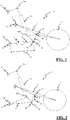
figure 1 is a schematic view of a first embodiment of the oscillation device according to the invention; -
figure 2 is a schematic view of a second embodiment of the oscillation device according to the invention; -
figure 3 is a schematic view of a third embodiment of the oscillation device according to the invention; -
figure 4 is a schematic view of the means to vary the distance in a static and/or dynamic manner, provided in the embodiments offigures 1, 2 and3 ; -
figures 5, 6 and 7 are schematic longitudinal sectional views of three different gas springs used with the distance variation means shown infigure 4 ; -
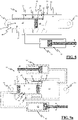
figure 8 shows a longitudinal sectional view of distance variation means according to a further embodiment of the invention; -
figure 9a shows a longitudinal sectional view of distance variation means according to an embodiment different from the one shown infigure 8 ; -
figure 9b shows a longitudinal sectional view of distance variation means according tofigure 9a in a different position of the dividing wall and of the further dividing wall. - With particular reference to such
figures, 1 denotes the oscillation system of the swingarm of a wheel according to the invention. In particular, in the embodiments of the invention described hereunder,such swingarm 1 is used for theback wheel 3 of a two-wheeled vehicle such as, for example, a motorcycle. - With reference to
figure 1 , according to a first embodiment of the invention, theoscillation system 1 of theswingarm 2 of awheel 3 with respect to theframe 4 of a vehicle, in particular of a motorcycle (or motorbike), wherein theswingarm 2 is rotatably constrained to theframe 4 at afirst pin 5, comprises a connectingrod 6 and acrank 7, wherein the connectingrod 6 in turn comprises afirst end 6a connected to theframe 4 and asecond end 6b rotatably constrained to the crank 7 at a furtherfirst end 7a of thecrank 7, and wherein thecrank 7 comprises a furthersecond end 7b rotatably constrained to theswingarm 2 at a second pin 8 distinct from thefirst pin 5. - It should be noted that such solution is adapted for any two-wheeled vehicle. Thus, in addition to being adapted for a motorcycle, it is also adapted for a bicycle, more specifically of the type known under the English name mountain bike.
- It should further be set forth that, although the
oscillation system 1 is usable more widely for the back wheel,such oscillation system 1 could however also be used on the front wheel of a two-wheeled vehicle, without thereby departing from the protection scope of the present invention. - According to the invention, the connecting
rod 6 comprises means 11 to vary the distance D in a static and/or dynamic way respectively between thefirst end 6a and thesecond end 6b of the connectingrod 6. - Moreover, in such embodiment, the
system 1 comprises afluidic damper 10 having athird end 10a connected indirectly, in this case, in a rotatable manner to theframe 4 and afourth end 10b connected directly in a rotatable manner to the crank 7, in a position distinct from the firstfurther end 7a and the secondfurther end 7b. Still, the connectingrod 6 is also rotatably constrained to theframe 4 at itsfirst end 6a. - In such configuration, the distance variation means 11 allow the user to obtain multiple variations of the attitude of the motorcycle, simply by increasing or decreasing the distance between the two
ends rod 6. Moreover, the distance variation D between the twoends - Moreover, the distance variation means 11 also act as a sort of additional suspension with respect to the
damper 10 by implementing a series of functions, as will become clearer from the description of the various distance adjustment means 11 described infigures 5 to 9b . In practice, the adjustment means 11 can be operated with the motorcycle stopped without the possibility to be able to modify the distance of the twoends - Although not shown in
figure 1 , in an alternative embodiment, thefourth end 10b of thefluidic damper 10 can be connected directly or indirectly in a rotatable manner to the same connectingrod 6, in a position distinct from thefirst end 6a and thesecond end 6b. - A further embodiment of the invention is shown in
figure 2 . Unlike the first embodiment, in this embodiment thecrank 7 comprises means 11 to vary the distance D in a static and/or dynamic way respectively between the furtherfirst end 7a and furthersecond end 7b of the crank. - In this embodiment, the
damper 10 has athird end 10a connected indirectly in a rotatable manner to theframe 4 and afourth end 10b connected directly or indirectly in a rotatable manner to the connectingrod 6, in a position distinct from thefirst end 6a andsecond end 6b. Also in this case, the connectingrod 6 is also rotatably constrained to theframe 4 at thefirst end 6a. - Although not shown in
figure 2 , in an alternative embodiment thefourth end 10b of thefluidic damper 10 can be connected directly in a rotatable manner to the same crank 7, in a position distinct from the furtherfirst end 7a and furthersecond end 7b. - In a third embodiment of the invention shown in
figure 3 , thecrank 7 comprises afirst damper 10 having athird end 10a connected directly or indirectly in a rotatable manner to the connectingrod 6 at thesecond end 6b, and afourth end 10b connected directly or indirectly in a rotatable manner to theswingarm 2 at a point different from thefirst pivot pin 5. Thus, in particular, thecrank 7 is in fact thedamper 10 and, thus, the furtherfirst end 7a coincides with thethird end 10a, while the furthersecond end 7b coincides with thefourth end 10b. The distance variation means 11 are thus arranged at the connectingelement 6. The connectingrod 6 comprises the variation means 11 of the distance D. In practice, thecrank 7 comprises thedamper 10 and theend points crank 7 thus correspond to theend points damper 10. - It should be noted that the term crank 7 must be understood as an element, or a second connecting rod, able to ensure the operation of the kinematic system in which it is inserted.
- In all other embodiments of the invention described above, the distance variation means 11 comprise a fluid-
transfer device 20. Such fluid-transfer device 20 comprises acylinder 21 having afirst chamber 22 and asecond chamber 23 and apiston 24 which slides within thecylinder 21 thus varying the dimensions of thefirst chamber 22 and thesecond chamber 23. Thecylinder 21 is also directly or indirectly integral with afirst portion 25a of the connectingrod 6, in the case of the first and third embodiments of the invention, or of thecrank 7, in the case of the second embodiment of the invention, and thepiston 24 is directly or indirectly integral with asecond portion 25b of the connectingrod 6, in the case of the first and third embodiments of the invention, or of thecrank 7, in the case of the second embodiment of the invention. It should be noted that whenever thepiston 24 is integral with thefirst portion 25a and thecylinder 21 is integral with thesecond portion 25b, the solution thus obtained would anyhow fall within the protection scope of the present invention. - Still, although not shown herein, said distance variation means 11 can also comprise at least one elastic element functionally combined with the
transfer device 20 and acting for at least part of the stroke of thepiston 24 with respect to saidcylinder 21. According to such embodiment not shown, such elastic element is a spring coaxial to thecylinder 21 of thetransfer device 20, or also an elastomer or other similar means. - According to the embodiments described in
figures 5 to 9b , the distance variation means 11 comprise agas spring 26 functionally combined with thesecond chamber 23 and/or thefirst chamber 22 of thecylinder 21. Thegas spring 26 in turn comprises athird chamber 27 and afourth chamber 28. Suchthird chamber 27 contains a gas such as, for example, air. Moreover, thethird chamber 27 and thefourth chamber 28 are separated from each other, directly or indirectly, by a dividingwall 29 which is sliding, or deformable, in such a way to vary the volume of thethird chamber 27 andfourth chamber 28 depending on the position of thepiston 24 with respect to thecylinder 21 to vary the volume, or pressure, of the gas within thethird chamber 27. - Still, the
fourth chamber 28 is in fluidic communication with thesecond chamber 23. Thefourth chamber 28 and thesecond chamber 23 contain an incompressible fluid that is transferred between thesecond chamber 23 and thefourth chamber 24, and vice versa, according to the variation of the position of thepiston 24 with respect to thecylinder 21. The dividingwall 29 is also sliding or deformable depending on the volume of incompressible fluid transferred from thesecond chamber 23 to thefourth chamber 28 and vice versa (seefigures 4 and5 ). - According to the embodiment described in
figure 5 , thethird chamber 27 and thefourth chamber 28 are formed inside atank 100 and the dividingwall 29 is slidable, or deformable, within thetank 100 to define the extent of thethird chamber 27 and thefourth chamber 28. In practice, thegas spring 26 is separated from thetransfer device 20. - A
limit stop 43, able to impede the displacement of the dividingwall 29 whenever the gas inside the third chamber increases in pressure, is also present inside thetank 100.Such limit stop 43 is arranged at about half thetank 100. This ensures the possibility to pre-compress the gas, the length of thecylinder 21 of the fluid-transfer device 20 being the same. - In this embodiment, the
transfer device 20 comprises aduct 31 for fluidically connecting thefourth chamber 28 to thesecond chamber 23 for transferring the incompressible fluid between thesecond chamber 23 and thefourth chamber 28, and vice versa.Such duct 31 is outside both thetransfer device 20 and thegas spring 26. - Such solution allows to make the distance adjustment means 11 work so as to constitute, in addition to a system for easily varying the static geometries of the suspension of the motorcycle, a system for varying the overall stiffness of the suspension depending on the load, in particular for significantly decreasing the stiffness at the exceeding of the load produced by the pressure of the gas contained within the
third chamber 27 and acting on the membrane orseparator 29. - An embodiment similar to that of
figure 5 is shown infigure 6 . In this solution, thegas spring 26 also comprises afurther chamber 70 connected by means of thehole 75 to the outer environment and arranged between thethird chamber 27 and thefourth chamber 28, and at least one further dividingwall 71 to separate thefurther chamber 70 from thefourth chamber 28. Thegas spring 26 also comprises anelastic spring 80 having afirst end 81 resting on thefirst dividing wall 29 and asecond end 82 resting on the further dividingwall 71. Thefurther chamber 70 and the further dividing wall are in turn arranged within thetank 100. - It should be noted that in another embodiment not shown herein, the
hole 75 may also not be present, without thereby departing from the protection scope of the present invention. - In this solution, the
elastic spring 80 replaces a possible elastic element combined with the fluid-transfer device 20, thus making the solution even more compact. - Another embodiment of the invention, in which the
gas spring 26 comprises afifth chamber 60 and asecond dividing wall 61 to separate thethird chamber 27 from thefifth chamber 60, is shown infigure 7 . Thesecond dividing wall 61 is sliding, or deformable, in such a way to vary the volume of thethird chamber 27 and of thefifth chamber 60. Thefifth chamber 60 and thesecond dividing wall 61 are in turn arranged within thetank 100. - In the embodiments described above, the
gas spring 26 can comprise first means 50 to adjust the pressure of the gas within thethird chamber 27. - In particular, such embodiment is shown only in
figure 7 but can however also be implemented in the solutions shown infigures 5 and 6 . - An embodiment in which the first adjustment means 50 also comprise at least one
sixth chamber 62 fluidically connected to thefifth chamber 60 is on the other hand shown infigure 7 . Thesixth chamber 62 and thefifth chamber 60 contain an incompressible fluid. Such incompressible fluid is transferred by the first adjustment means 50 between thefifth chamber 60 and thesixth chamber 62, and vice versa. Thesecond dividing wall 61 is also sliding, or deformable, depending on the volume of incompressible fluid transferred from the fifth chamber to the sixth chamber, and vice versa. - In such embodiment, the first means 50 comprise an actuator for fluidically connecting the
sixth chamber 62, thefifth chamber 60 and thefourth chamber 28 to each other, and a three-way valve 64 for distributing the incompressible fluid between thefifth chamber 60 and thefourth chamber 28. Such solution allows to control the pressure changes of the incompressible liquid present within thefifth chamber 60 and thefourth chamber 28, as well as the pressure of the gas present within thethird chamber 27, with a single actuator. In the light of this, the characteristics of pressure and volume of the gas contained within thethird chamber 27 are closely connected to the characteristics of the fluid contained within thefourth chamber 28 or thesecond chamber 23, since the latter is fluidically connected to the fourth chamber. - Such solution thus allows to adjust the following characteristics of the adjustment device independently: static length D between the
ends chamber 27, which instead regulate the dynamic characteristics of the suspension as a whole. - In alternative to the embodiment described above, the
transfer device 10 comprises second means 90 for adjusting the pressure of the incompressible fluid contained within the second chamber 23 (and thus also within the fourth chamber 28), whereas the first means 50 would thus only adjust the pressure of the fluid contained within the third chamber 27 (also seefigures 9a and9b ). - In the embodiments described above, the
first chamber 22 of thetransfer device 20 can contain air and be fluidically connected to the outer environment. - According to the embodiment described in
figure 8 , thetransfer device 20 comprises arod 40 integrally combined with thepiston 24 and adapted to make thepiston 24 slide inside thecylinder 21. Theend 6a of the rod is also the end of the connectingelement 6. Therod 40 is provided with aninner housing 32. Suchinner housing 32 comprises thethird chamber 27, thefourth chamber 28 and the dividingwall 29 of theaforementioned gas spring 26. This way, thegas spring 26 is thus not outside the fluid-transfer device 20 but inside it, thus significantly reducing the volume of the adjustment means 11. Moreover, theduct 31 is made at least partially within therod 40 and thepiston 24 to fluidically connect thesecond chamber 23 to thefourth chamber 28. - As described above, also in this case, the
housing 32 has alimit stop 43 able to impede the displacement of the dividingwall 29 whenever the gas inside thethird chamber 27 increases in pressure.Such limit stop 43 is arranged at an end of thehousing 32. - Also in such embodiment, the
first chamber 22 of thetransfer device 20 can contain air and be fluidically connected to the outer environment. Moreover, thefirst chamber 22 of thecylinder 21 is fluidically separated from thesecond chamber 23. Although not shown herein, thehousing 32 could contain agas spring 26 of the type shown infigure 6 and described above therein. The first adjustment means 50 can comprise anactuator 51 that adjusts the pressure of the incompressible liquid within thefirst chamber 23 and thus within thefourth chamber 28 and, ultimately, also the pressure of the gas within thethird chamber 27. - Still, the
housing 32, in an alternative manner, could contain agas spring 26 of the type shown infigure 7 and described above with the presence of first means 50 that comprise an actuator for fluidically connecting thesixth chamber 62, thefifth chamber 60 and thefourth chamber 28 to each other, and a three-way valve 64 for distributing the incompressible fluid between thefifth chamber 60 and thefourth chamber 28. - In alternative to the embodiment described above, the adjustment means 11 can comprise second means 90 for adjusting the pressure of the incompressible fluid contained within the second chamber 23 (and thus also within the fourth chamber 28), whereas the first means 50 would thus only adjust the pressure of the fluid contained within the
fifth chamber 60 and thus ultimately within thethird chamber 27. This way, the first adjustment means 50 and the second adjustment means 90 would be independent of each other. - Also in this embodiment, the
first chamber 22 contains air and is fluidically connected to the outer environment. - According to a further embodiment of the invention shown in
figures 9a and9b , thefirst chamber 22 of thecylinder 21 is this time fluidically connected to thesecond chamber 23 by means of theduct 31. - Also in this embodiment, the
housing 32 comprises ahole 34 formed within therod 40. Moreover, the distance adjustment means 11 comprise first means 50 to adjust the gas pressure within thethird chamber 27. In this regard, thegas spring 26 offigures 9a and9b comprises afifth chamber 60 and asecond dividing wall 61 to separate thethird chamber 27 from thefifth chamber 60. Thesecond dividing wall 61 is thus sliding, or deformable, so as to vary the volume of thethird chamber 27 and of thefifth chamber 60. Thefifth chamber 60 and thesecond dividing wall 61 are arranged within the hole formed in thehousing 32. - The
housing 32 thus also has asecond limit stop 44 arranged at a precise distance from the end of thehousing 32. This ensures the possibility to pre-compress the gas, the length of thecylinder 21 of the fluid-transfer device 20 being the same. - The first adjustment means 50 also comprise a
sixth chamber 62 fluidically connected to thefifth chamber 60. Thesixth chamber 62 and thefifth chamber 60 contain an incompressible fluid that is transferred by the first adjustment means 50 between thefifth chamber 60 and thesixth chamber 62 and vice versa. Thesecond dividing wall 61 is further sliding or deformable, depending on the volume of incompressible fluid transferred from thefifth chamber 60 to thesixth chamber 62, and vice versa. - The
transfer device 10 also comprises second means 90 for adjusting the pressure of the incompressible fluid of the first 22 and second 23 chambers. -
Figure 9b shows how the first adjustment means 50, once activated, have caused the reduction of thethird chamber 27, i.e. the compression of the gas of thegas spring 26. Simultaneously, the second means 90 are activated so as to introduce oil both into thefirst chamber 22 and thesecond chamber 23. This causes the increase of the distance D both between the twoends element 6, whenever it is provided with distance adjustment means 11, or between the twoends crank 7, whenever the latter is provided withmeans 11 for adjusting thedistance 11. - The first adjustment means 50 also comprise a
sixth chamber 62 fluidically connected to thefifth chamber 60. Thesixth chamber 62 and thefifth chamber 60 contain an incompressible fluid that is transferred by the first adjustment means 50 between thefifth chamber 60 and thesixth chamber 62 and vice versa. Thesecond dividing wall 61 is further sliding or deformable, depending on the volume of incompressible fluid transferred from thefifth chamber 60 to thesixth chamber 62, and vice versa. - In an embodiment not shown herein, alternative to the one described above and shown in
figure 9a , thegas spring 26 can also comprise afurther chamber 70 connected to the outer environment and arranged between thethird chamber 27 and thefourth chamber 28 and at least one further dividingwall 71 to separate thefurther chamber 70 from thefourth chamber 28. Thegas spring 26 also comprises anelastic spring 80 having afirst end 81 resting on thefirst dividing wall 29 and asecond end 82 resting on the further dividingwall 71.
Claims (19)
- Oscillation system (1) of the swingarm (2) of a wheel (3), preferably a back wheel, with respect to the frame (4) of a vehicle, preferably a two-wheeled one, even more preferably a motorcycle, wherein said swingarm is rotatably constrainable to said frame at a first pin (5), said system comprising at least one connecting rod (6) and at least one crank (7), wherein said connecting rod (6) comprises a first end (6a) connectable to said frame and a second end (6b) rotatably constrained to said crank (7) at a further first end (7a) of said crank (7), and wherein said crank (7) comprises a further second end (7b) rotatably constrained to said swingarm at a second pin (8) distinct from said first pin (5), wherein in said connecting rod (6) and/or said crank (7) comprise(s) means (11) to vary the distance (D) in a static and/or dynamic manner between said first end (6a) and said second end (6b) of said connecting rod (6), respectively, and/or between said further first end (7a) and said further second end (7b) of said crank (7), said distance variation means (11) comprising at least one fluid-transfer device (20), said fluid-transfer device comprising a cylinder (21) having a first chamber (22) and a second chamber (23), and a piston (24) sliding within said cylinder (21) thus varying the dimensions of said first chamber and said second chamber, and wherein said cylinder (21) is directly or indirectly integral with a first portion (25a) of said connecting rod (6), or of said crank (7), and said piston (24) is directly or indirectly integral with a second portion (25b) of said connecting rod (6), or of said crank (7), and wherein said distance variation means (11) comprise a gas spring (26) functionally combined with said at least one second chamber (23) and/or with said at least one first chamber (22) of said cylinder (21).
- System according to claim 1, characterized in that it comprises a first damper (10) having a third end (10a) connectable directly, or indirectly, in a rotatable manner to said frame (4) and a fourth end (10b) connected directly or indirectly in a rotatable manner to said connecting rod (6), or to said crank (7), in a position distinct from said first end and said second end, or from said further first end and said further second end, said connecting rod (6) being further rotatably constrainable to said frame (4) at said first end (6a).
- System according to claim 1, characterized in that said crank (7) comprises a first damper (10) having a third end (10a) connected directly or indirectly in a rotatable manner to said connecting rod (6) at said second end, and a fourth end (10b) connected directly or indirectly in a rotatable manner to said swingarm (2) at a point different from said first pivot pin (5).
- System according to one or more of claims 1 to 3, characterized in that said gas spring comprises at least one third chamber (27) and one fourth chamber (28), said at least one third chamber (27) containing a gas, wherein said at least one third chamber (27) and said at least one fourth chamber (28) are separated from each other, directly or indirectly, by at least one dividing wall (29) which is sliding, or deformable, in such a way to vary the volume of said third chamber (27) and said fourth chamber (28) depending on the position of said piston (24) with respect to said cylinder (21) to vary the volume, or pressure, of the gas within said at least one third chamber (27).
- System according to one or more of claims 1 to 4, characterized in that said at least one fourth chamber (28) is in fluidic communication with said at least second chamber (23), said at least one fourth chamber (28) and said at least one second chamber (23) containing an incompressible fluid, said incompressible fluid being transferred between said at least one second chamber (23) and said at least one fourth chamber (28) and vice versa, as the position of said piston (24) with respect to said cylinder (21) varies, said at least one dividing wall (29) also being sliding or deformable depending on the volume of incompressible fluid transferred from said at least one second chamber (23) to said at least one fourth chamber (28) and vice versa.
- System according to claim 4 or 5, characterized in that said at least one third chamber (27) and said at least one fourth chamber (28) are formed inside a tank (100) and that said at least one dividing wall (29) is slidable, or deformable, within said tank to define said at least one third chamber (27) and said at least one fourth chamber (28).
- System according to claim 5 or 6, characterized in that said transfer device (20) comprises at least one duct (31) for fluidically connecting said at least one fourth chamber (28) to said at least one second chamber (23) for transferring said incompressible fluid between said at least one second chamber (23) and said at least one fourth chamber (28), and vice versa.
- System according to claim 7, characterized in that said transfer device (20) comprises a rod (40) integrally combined with said piston (24) and adapted to slide said piston within said cylinder (21), said rod (40) being provided with an inner housing (32), said inner housing comprising said at least one third chamber (27), said at least one fourth chamber (28) and said dividing wall (29), said duct (31) being made at least partially within said rod and/or said piston (24) to fluidically connect said at least one second chamber (23) to said at least one fourth chamber (28).
- System according to claim 8, characterized in that said first chamber of said cylinder is fluidically separated from said second chamber.
- System (1) according to one or more of claims 1 to 9, characterized in that said at least one first chamber (22) contains air and is fluidically connected to the outer environment.
- System according to claim 8, characterized in that said at least one first chamber (22) of said cylinder (21) is fluidically connected to said at least one second chamber (23) by means of said duct (31).
- System (1) according to one or more of claims 4 to 11, characterized in that said at least one gas spring comprises first means (50) for adjusting the pressure of said gas within said at least one third chamber (27).
- System according to one or more of claims 8 to 12, characterized in that said housing (32) comprises a hole (34) formed within said rod (40).
- System according to one or more of claims 6 to 13, characterized in that said gas spring comprises a fifth chamber (60) and at least one second dividing wall (61) to separate said at least one third chamber (27) from said at least fifth chamber (60), said second dividing wall (61) being sliding or deformable, so as to vary the volume of said third chamber (27) and said fifth chamber (60), said fifth chamber (60) and said second dividing wall (61) being arranged within said hole (34) or within said tank (100).
- System (1) according to at least claims 12 and 14, characterized in that said first adjustment means (50) also comprising at least one sixth chamber (62) fluidically connected to said fifth chamber (60), said at least one sixth chamber (62) and said at least one fifth chamber (60) containing an incompressible fluid, said incompressible fluid being transferred by said first adjustment means (50) between said at least one fifth chamber (60) and said sixth chamber (62) and vice versa, said at least one second dividing wall (61) being further sliding or deformable, depending on the volume of incompressible fluid transferred from said at least one fifth chamber to said at least one sixth chamber, and vice versa.
- System (1) according to one or more of claims 4 to 15, characterized in that said gas spring also comprises a further chamber (70), preferably connected to the outer environment, arranged between said third chamber (27) and said fourth chamber (28) and at least one further dividing wall (71) to separate said further chamber (70) from said fourth chamber (28), said gas spring also comprising at least one elastic spring (80) having a first end (81) resting on said first dividing wall (29) and a second end (82) resting on said further dividing wall (71).
- System (1) according to one or more of claims 12 to 16, characterized in that said first means (50) comprise an actuator for fluidically connecting said sixth chamber (62) to said fifth chamber (60) and to said fourth chamber (28) and/or said first chamber (22), and at least one valve (64) for distributing said incompressible fluid between said fifth chamber (60) and said fourth chamber (28) and/or said first chamber (22).
- System (1) according to one or more of claims 4 to 9 and 11 to 15, characterized in that said transfer device (10) comprises second means (90) to adjust the pressure of the incompressible fluid of said at least one first chamber (22) and/or said at least one second chamber (23) and/or, directly or indirectly, the pressure of said gas within said third chamber (27).
- Two-wheeled vehicle comprising a frame (4), at least one wheel (3), preferably a back wheel, a swingarm (2) for said wheel (3) and an oscillation system of the swingarm (2) with respect to said frame (4) according to one or more of claims 1 to 18.
Applications Claiming Priority (1)
| Application Number | Priority Date | Filing Date | Title |
|---|---|---|---|
| IT102021000008522A IT202100008522A1 (en) | 2021-04-06 | 2021-04-06 | OSCILLATION SYSTEM OF THE SWINGARM OF A WHEEL WITH RESPECT TO THE FRAME OF A VEHICLE. |
Publications (3)
| Publication Number | Publication Date |
|---|---|
| EP4086151A1 true EP4086151A1 (en) | 2022-11-09 |
| EP4086151C0 EP4086151C0 (en) | 2025-07-16 |
| EP4086151B1 EP4086151B1 (en) | 2025-07-16 |
Family
ID=77021750
Family Applications (1)
| Application Number | Title | Priority Date | Filing Date |
|---|---|---|---|
| EP22166849.4A Active EP4086151B1 (en) | 2021-04-06 | 2022-04-05 | Oscillation system of the swingarm of a wheel with respect to the frame of a vehicle |
Country Status (2)
| Country | Link |
|---|---|
| EP (1) | EP4086151B1 (en) |
| IT (1) | IT202100008522A1 (en) |
Cited By (2)
| Publication number | Priority date | Publication date | Assignee | Title |
|---|---|---|---|---|
| EP4403386A1 (en) * | 2023-01-18 | 2024-07-24 | BAE SYSTEMS plc | Suspension strut assembly |
| WO2024153911A1 (en) * | 2023-01-18 | 2024-07-25 | Bae Systems Plc | Suspension strut assembly |
Citations (6)
| Publication number | Priority date | Publication date | Assignee | Title |
|---|---|---|---|---|
| JPS5923710A (en) * | 1982-07-29 | 1984-02-07 | Yamaha Motor Co Ltd | Pressure governor of air spring for vehicle |
| JPS6018476A (en) * | 1983-07-12 | 1985-01-30 | ヤマハ発動機株式会社 | Regulator for car height of motorcycle |
| JPS6078804A (en) * | 1983-10-04 | 1985-05-04 | Yamaha Motor Co Ltd | Pneumatic spring type car height adjuster |
| EP1535828A2 (en) | 2003-11-27 | 2005-06-01 | Showa Corporation | Suspension apparatus of vehicle |
| US20060196741A1 (en) | 2003-03-25 | 2006-09-07 | Sven Kindblom | Shock absorber for height adjustment |
| WO2017115393A2 (en) | 2015-12-31 | 2017-07-06 | Berti Giacomo | Motorcycle with multi-configuration chassis |
Family Cites Families (4)
| Publication number | Priority date | Publication date | Assignee | Title |
|---|---|---|---|---|
| DE3044016A1 (en) * | 1980-11-22 | 1982-06-24 | Fichtel & Sachs Ag, 8720 Schweinfurt | Temp. corrected hydropneumatic damper - has limited flow connection to high pressure reservoir |
| DE10114262A1 (en) * | 2001-03-22 | 2002-09-26 | Denk Engineering Gmbh | Hydraulic shock absorber has piston attached to tubular piston rod which acts as oil reservoir, oil being sucked into working chamber between it and working cylinder when shock absorber is compressed |
| RU2006121127A (en) * | 2003-08-12 | 2008-01-20 | РОБЕРТСОН Грэм К (AU) | SHOCK ABSORBER ASSEMBLY |
| EP3753763B1 (en) * | 2019-06-20 | 2022-10-19 | The Dynamic Engineering Solution Pty Ltd | Vehicle suspension system |
-
2021
- 2021-04-06 IT IT102021000008522A patent/IT202100008522A1/en unknown
-
2022
- 2022-04-05 EP EP22166849.4A patent/EP4086151B1/en active Active
Patent Citations (6)
| Publication number | Priority date | Publication date | Assignee | Title |
|---|---|---|---|---|
| JPS5923710A (en) * | 1982-07-29 | 1984-02-07 | Yamaha Motor Co Ltd | Pressure governor of air spring for vehicle |
| JPS6018476A (en) * | 1983-07-12 | 1985-01-30 | ヤマハ発動機株式会社 | Regulator for car height of motorcycle |
| JPS6078804A (en) * | 1983-10-04 | 1985-05-04 | Yamaha Motor Co Ltd | Pneumatic spring type car height adjuster |
| US20060196741A1 (en) | 2003-03-25 | 2006-09-07 | Sven Kindblom | Shock absorber for height adjustment |
| EP1535828A2 (en) | 2003-11-27 | 2005-06-01 | Showa Corporation | Suspension apparatus of vehicle |
| WO2017115393A2 (en) | 2015-12-31 | 2017-07-06 | Berti Giacomo | Motorcycle with multi-configuration chassis |
Cited By (2)
| Publication number | Priority date | Publication date | Assignee | Title |
|---|---|---|---|---|
| EP4403386A1 (en) * | 2023-01-18 | 2024-07-24 | BAE SYSTEMS plc | Suspension strut assembly |
| WO2024153911A1 (en) * | 2023-01-18 | 2024-07-25 | Bae Systems Plc | Suspension strut assembly |
Also Published As
| Publication number | Publication date |
|---|---|
| IT202100008522A1 (en) | 2022-10-06 |
| EP4086151C0 (en) | 2025-07-16 |
| EP4086151B1 (en) | 2025-07-16 |
Similar Documents
| Publication | Publication Date | Title |
|---|---|---|
| AU2005221449C1 (en) | Vehicular suspension system | |
| US7686309B2 (en) | Hydraulic system for a vehicle suspension | |
| CN101287926B (en) | Damping valve with controllable amplitude | |
| US6290035B1 (en) | Acceleration sensitive damping for automotive dampers | |
| US10202166B2 (en) | Integrated and self-contained suspension assembly having an on-the-fly adjustable air spring | |
| US6460664B1 (en) | Independently tunable variable bleed orifice | |
| US9238489B2 (en) | Driver's cab suspension device with roll stabilizing means | |
| US7331627B2 (en) | Lateral control rod for a cab suspension system | |
| CN111379811A (en) | Damper with control valve | |
| US6311961B1 (en) | Hydro-pneumatic suspension unit for land-vehicles | |
| EP2046589B1 (en) | System to control the trim of motorcycles with three or four wheels | |
| US20050218573A1 (en) | ATV coil spring preload equalizing adjuster | |
| EP4086151B1 (en) | Oscillation system of the swingarm of a wheel with respect to the frame of a vehicle | |
| WO2007098559A1 (en) | Hydraulic system for a vehicle suspension | |
| US6382372B1 (en) | Ported disc variable bleed orifice | |
| US10696353B2 (en) | Motorcycle having a fluid-actuated lowering device | |
| AU2005266861B2 (en) | Hydraulic vehicle suspension system | |
| CN112424501A (en) | Spring rate adjuster | |
| EP4070974A1 (en) | Shock absorber for wheeled vehicles | |
| EP2643611B1 (en) | Frequency dependent damping | |
| US20040256186A1 (en) | Spring-less monotube shock absorber |
Legal Events
| Date | Code | Title | Description |
|---|---|---|---|
| PUAI | Public reference made under article 153(3) epc to a published international application that has entered the european phase |
Free format text: ORIGINAL CODE: 0009012 |
|
| STAA | Information on the status of an ep patent application or granted ep patent |
Free format text: STATUS: THE APPLICATION HAS BEEN PUBLISHED |
|
| AK | Designated contracting states |
Kind code of ref document: A1 Designated state(s): AL AT BE BG CH CY CZ DE DK EE ES FI FR GB GR HR HU IE IS IT LI LT LU LV MC MK MT NL NO PL PT RO RS SE SI SK SM TR |
|
| STAA | Information on the status of an ep patent application or granted ep patent |
Free format text: STATUS: REQUEST FOR EXAMINATION WAS MADE |
|
| 17P | Request for examination filed |
Effective date: 20230509 |
|
| RBV | Designated contracting states (corrected) |
Designated state(s): AL AT BE BG CH CY CZ DE DK EE ES FI FR GB GR HR HU IE IS IT LI LT LU LV MC MK MT NL NO PL PT RO RS SE SI SK SM TR |
|
| RIC1 | Information provided on ipc code assigned before grant |
Ipc: B62K 25/04 20060101ALN20230814BHEP Ipc: B60G 15/12 20060101ALI20230814BHEP Ipc: B60G 17/04 20060101ALI20230814BHEP Ipc: B60G 11/56 20060101ALI20230814BHEP Ipc: B60G 11/26 20060101ALI20230814BHEP Ipc: B60G 3/20 20060101ALI20230814BHEP Ipc: B60G 3/14 20060101ALI20230814BHEP Ipc: B62K 25/28 20060101AFI20230814BHEP |
|
| STAA | Information on the status of an ep patent application or granted ep patent |
Free format text: STATUS: EXAMINATION IS IN PROGRESS |
|
| 17Q | First examination report despatched |
Effective date: 20231011 |
|
| RAP3 | Party data changed (applicant data changed or rights of an application transferred) |
Owner name: UMBRIA KINETICS SRL |
|
| GRAP | Despatch of communication of intention to grant a patent |
Free format text: ORIGINAL CODE: EPIDOSNIGR1 |
|
| STAA | Information on the status of an ep patent application or granted ep patent |
Free format text: STATUS: GRANT OF PATENT IS INTENDED |
|
| RIC1 | Information provided on ipc code assigned before grant |
Ipc: B62K 25/04 20060101ALN20250123BHEP Ipc: F16F 9/06 20060101ALI20250123BHEP Ipc: B60G 15/12 20060101ALI20250123BHEP Ipc: B60G 17/04 20060101ALI20250123BHEP Ipc: B60G 11/56 20060101ALI20250123BHEP Ipc: B60G 11/26 20060101ALI20250123BHEP Ipc: B60G 3/20 20060101ALI20250123BHEP Ipc: B60G 3/14 20060101ALI20250123BHEP Ipc: B62K 25/28 20060101AFI20250123BHEP |
|
| INTG | Intention to grant announced |
Effective date: 20250211 |
|
| RIN1 | Information on inventor provided before grant (corrected) |
Inventor name: GIULIANI, FEDERICO |
|
| GRAS | Grant fee paid |
Free format text: ORIGINAL CODE: EPIDOSNIGR3 |
|
| GRAA | (expected) grant |
Free format text: ORIGINAL CODE: 0009210 |
|
| STAA | Information on the status of an ep patent application or granted ep patent |
Free format text: STATUS: THE PATENT HAS BEEN GRANTED |
|
| AK | Designated contracting states |
Kind code of ref document: B1 Designated state(s): AL AT BE BG CH CY CZ DE DK EE ES FI FR GB GR HR HU IE IS IT LI LT LU LV MC MK MT NL NO PL PT RO RS SE SI SK SM TR |
|
| REG | Reference to a national code |
Ref country code: GB Ref legal event code: FG4D |
|
| REG | Reference to a national code |
Ref country code: CH Ref legal event code: EP Ref country code: DE Ref legal event code: R096 Ref document number: 602022017525 Country of ref document: DE |
|
| REG | Reference to a national code |
Ref country code: IE Ref legal event code: FG4D |
|
| U01 | Request for unitary effect filed |
Effective date: 20250813 |
|
| U07 | Unitary effect registered |
Designated state(s): AT BE BG DE DK EE FI FR IT LT LU LV MT NL PT RO SE SI Effective date: 20250821 |
|
| PG25 | Lapsed in a contracting state [announced via postgrant information from national office to epo] |
Ref country code: IS Free format text: LAPSE BECAUSE OF FAILURE TO SUBMIT A TRANSLATION OF THE DESCRIPTION OR TO PAY THE FEE WITHIN THE PRESCRIBED TIME-LIMIT Effective date: 20251116 |
|
| PG25 | Lapsed in a contracting state [announced via postgrant information from national office to epo] |
Ref country code: NO Free format text: LAPSE BECAUSE OF FAILURE TO SUBMIT A TRANSLATION OF THE DESCRIPTION OR TO PAY THE FEE WITHIN THE PRESCRIBED TIME-LIMIT Effective date: 20251016 |
|
| PG25 | Lapsed in a contracting state [announced via postgrant information from national office to epo] |
Ref country code: HR Free format text: LAPSE BECAUSE OF FAILURE TO SUBMIT A TRANSLATION OF THE DESCRIPTION OR TO PAY THE FEE WITHIN THE PRESCRIBED TIME-LIMIT Effective date: 20250716 |
|
| PG25 | Lapsed in a contracting state [announced via postgrant information from national office to epo] |
Ref country code: GR Free format text: LAPSE BECAUSE OF FAILURE TO SUBMIT A TRANSLATION OF THE DESCRIPTION OR TO PAY THE FEE WITHIN THE PRESCRIBED TIME-LIMIT Effective date: 20251017 |
|
| PG25 | Lapsed in a contracting state [announced via postgrant information from national office to epo] |
Ref country code: PL Free format text: LAPSE BECAUSE OF FAILURE TO SUBMIT A TRANSLATION OF THE DESCRIPTION OR TO PAY THE FEE WITHIN THE PRESCRIBED TIME-LIMIT Effective date: 20250716 |
|
| PG25 | Lapsed in a contracting state [announced via postgrant information from national office to epo] |
Ref country code: RS Free format text: LAPSE BECAUSE OF FAILURE TO SUBMIT A TRANSLATION OF THE DESCRIPTION OR TO PAY THE FEE WITHIN THE PRESCRIBED TIME-LIMIT Effective date: 20251016 |
|
| PG25 | Lapsed in a contracting state [announced via postgrant information from national office to epo] |
Ref country code: ES Free format text: LAPSE BECAUSE OF FAILURE TO SUBMIT A TRANSLATION OF THE DESCRIPTION OR TO PAY THE FEE WITHIN THE PRESCRIBED TIME-LIMIT Effective date: 20250716 |
|
| PG25 | Lapsed in a contracting state [announced via postgrant information from national office to epo] |
Ref country code: SM Free format text: LAPSE BECAUSE OF FAILURE TO SUBMIT A TRANSLATION OF THE DESCRIPTION OR TO PAY THE FEE WITHIN THE PRESCRIBED TIME-LIMIT Effective date: 20250716 |
|
| PG25 | Lapsed in a contracting state [announced via postgrant information from national office to epo] |
Ref country code: CZ Free format text: LAPSE BECAUSE OF FAILURE TO SUBMIT A TRANSLATION OF THE DESCRIPTION OR TO PAY THE FEE WITHIN THE PRESCRIBED TIME-LIMIT Effective date: 20250716 |
|
| PG25 | Lapsed in a contracting state [announced via postgrant information from national office to epo] |
Ref country code: SK Free format text: LAPSE BECAUSE OF FAILURE TO SUBMIT A TRANSLATION OF THE DESCRIPTION OR TO PAY THE FEE WITHIN THE PRESCRIBED TIME-LIMIT Effective date: 20250716 |