EP4086087A1 - Tire tread and tire - Google Patents
Tire tread and tire Download PDFInfo
- Publication number
- EP4086087A1 EP4086087A1 EP22170552.8A EP22170552A EP4086087A1 EP 4086087 A1 EP4086087 A1 EP 4086087A1 EP 22170552 A EP22170552 A EP 22170552A EP 4086087 A1 EP4086087 A1 EP 4086087A1
- Authority
- EP
- European Patent Office
- Prior art keywords
- shoulder
- grooves
- circumferential
- groove
- axially
- Prior art date
- Legal status (The legal status is an assumption and is not a legal conclusion. Google has not performed a legal analysis and makes no representation as to the accuracy of the status listed.)
- Withdrawn
Links
Images



Classifications
-
- B—PERFORMING OPERATIONS; TRANSPORTING
- B60—VEHICLES IN GENERAL
- B60C—VEHICLE TYRES; TYRE INFLATION; TYRE CHANGING; CONNECTING VALVES TO INFLATABLE ELASTIC BODIES IN GENERAL; DEVICES OR ARRANGEMENTS RELATED TO TYRES
- B60C11/00—Tyre tread bands; Tread patterns; Anti-skid inserts
- B60C11/03—Tread patterns
- B60C11/032—Patterns comprising isolated recesses
-
- B—PERFORMING OPERATIONS; TRANSPORTING
- B60—VEHICLES IN GENERAL
- B60C—VEHICLE TYRES; TYRE INFLATION; TYRE CHANGING; CONNECTING VALVES TO INFLATABLE ELASTIC BODIES IN GENERAL; DEVICES OR ARRANGEMENTS RELATED TO TYRES
- B60C11/00—Tyre tread bands; Tread patterns; Anti-skid inserts
- B60C11/03—Tread patterns
- B60C11/0306—Patterns comprising block rows or discontinuous ribs
- B60C11/0309—Patterns comprising block rows or discontinuous ribs further characterised by the groove cross-section
-
- B—PERFORMING OPERATIONS; TRANSPORTING
- B60—VEHICLES IN GENERAL
- B60C—VEHICLE TYRES; TYRE INFLATION; TYRE CHANGING; CONNECTING VALVES TO INFLATABLE ELASTIC BODIES IN GENERAL; DEVICES OR ARRANGEMENTS RELATED TO TYRES
- B60C11/00—Tyre tread bands; Tread patterns; Anti-skid inserts
- B60C11/01—Shape of the shoulders between tread and sidewall, e.g. rounded, stepped or cantilevered
-
- B—PERFORMING OPERATIONS; TRANSPORTING
- B60—VEHICLES IN GENERAL
- B60C—VEHICLE TYRES; TYRE INFLATION; TYRE CHANGING; CONNECTING VALVES TO INFLATABLE ELASTIC BODIES IN GENERAL; DEVICES OR ARRANGEMENTS RELATED TO TYRES
- B60C11/00—Tyre tread bands; Tread patterns; Anti-skid inserts
- B60C11/03—Tread patterns
- B60C11/0304—Asymmetric patterns
-
- B—PERFORMING OPERATIONS; TRANSPORTING
- B60—VEHICLES IN GENERAL
- B60C—VEHICLE TYRES; TYRE INFLATION; TYRE CHANGING; CONNECTING VALVES TO INFLATABLE ELASTIC BODIES IN GENERAL; DEVICES OR ARRANGEMENTS RELATED TO TYRES
- B60C11/00—Tyre tread bands; Tread patterns; Anti-skid inserts
- B60C11/03—Tread patterns
- B60C11/0306—Patterns comprising block rows or discontinuous ribs
-
- B—PERFORMING OPERATIONS; TRANSPORTING
- B60—VEHICLES IN GENERAL
- B60C—VEHICLE TYRES; TYRE INFLATION; TYRE CHANGING; CONNECTING VALVES TO INFLATABLE ELASTIC BODIES IN GENERAL; DEVICES OR ARRANGEMENTS RELATED TO TYRES
- B60C11/00—Tyre tread bands; Tread patterns; Anti-skid inserts
- B60C11/03—Tread patterns
- B60C11/12—Tread patterns characterised by the use of narrow slits or incisions, e.g. sipes
- B60C11/1204—Tread patterns characterised by the use of narrow slits or incisions, e.g. sipes with special shape of the sipe
-
- B—PERFORMING OPERATIONS; TRANSPORTING
- B60—VEHICLES IN GENERAL
- B60C—VEHICLE TYRES; TYRE INFLATION; TYRE CHANGING; CONNECTING VALVES TO INFLATABLE ELASTIC BODIES IN GENERAL; DEVICES OR ARRANGEMENTS RELATED TO TYRES
- B60C11/00—Tyre tread bands; Tread patterns; Anti-skid inserts
- B60C11/03—Tread patterns
- B60C11/12—Tread patterns characterised by the use of narrow slits or incisions, e.g. sipes
- B60C11/1236—Tread patterns characterised by the use of narrow slits or incisions, e.g. sipes with special arrangements in the tread pattern
-
- B—PERFORMING OPERATIONS; TRANSPORTING
- B60—VEHICLES IN GENERAL
- B60C—VEHICLE TYRES; TYRE INFLATION; TYRE CHANGING; CONNECTING VALVES TO INFLATABLE ELASTIC BODIES IN GENERAL; DEVICES OR ARRANGEMENTS RELATED TO TYRES
- B60C11/00—Tyre tread bands; Tread patterns; Anti-skid inserts
- B60C11/03—Tread patterns
- B60C11/13—Tread patterns characterised by the groove cross-section, e.g. for buttressing or preventing stone-trapping
-
- B—PERFORMING OPERATIONS; TRANSPORTING
- B60—VEHICLES IN GENERAL
- B60C—VEHICLE TYRES; TYRE INFLATION; TYRE CHANGING; CONNECTING VALVES TO INFLATABLE ELASTIC BODIES IN GENERAL; DEVICES OR ARRANGEMENTS RELATED TO TYRES
- B60C11/00—Tyre tread bands; Tread patterns; Anti-skid inserts
- B60C11/01—Shape of the shoulders between tread and sidewall, e.g. rounded, stepped or cantilevered
- B60C2011/013—Shape of the shoulders between tread and sidewall, e.g. rounded, stepped or cantilevered provided with a recessed portion
-
- B—PERFORMING OPERATIONS; TRANSPORTING
- B60—VEHICLES IN GENERAL
- B60C—VEHICLE TYRES; TYRE INFLATION; TYRE CHANGING; CONNECTING VALVES TO INFLATABLE ELASTIC BODIES IN GENERAL; DEVICES OR ARRANGEMENTS RELATED TO TYRES
- B60C11/00—Tyre tread bands; Tread patterns; Anti-skid inserts
- B60C11/03—Tread patterns
- B60C2011/0337—Tread patterns characterised by particular design features of the pattern
- B60C2011/0339—Grooves
- B60C2011/0341—Circumferential grooves
-
- B—PERFORMING OPERATIONS; TRANSPORTING
- B60—VEHICLES IN GENERAL
- B60C—VEHICLE TYRES; TYRE INFLATION; TYRE CHANGING; CONNECTING VALVES TO INFLATABLE ELASTIC BODIES IN GENERAL; DEVICES OR ARRANGEMENTS RELATED TO TYRES
- B60C11/00—Tyre tread bands; Tread patterns; Anti-skid inserts
- B60C11/03—Tread patterns
- B60C2011/0337—Tread patterns characterised by particular design features of the pattern
- B60C2011/0339—Grooves
- B60C2011/0341—Circumferential grooves
- B60C2011/0348—Narrow grooves, i.e. having a width of less than 4 mm
-
- B—PERFORMING OPERATIONS; TRANSPORTING
- B60—VEHICLES IN GENERAL
- B60C—VEHICLE TYRES; TYRE INFLATION; TYRE CHANGING; CONNECTING VALVES TO INFLATABLE ELASTIC BODIES IN GENERAL; DEVICES OR ARRANGEMENTS RELATED TO TYRES
- B60C11/00—Tyre tread bands; Tread patterns; Anti-skid inserts
- B60C11/03—Tread patterns
- B60C2011/0337—Tread patterns characterised by particular design features of the pattern
- B60C2011/0339—Grooves
- B60C2011/0381—Blind or isolated grooves
-
- B—PERFORMING OPERATIONS; TRANSPORTING
- B60—VEHICLES IN GENERAL
- B60C—VEHICLE TYRES; TYRE INFLATION; TYRE CHANGING; CONNECTING VALVES TO INFLATABLE ELASTIC BODIES IN GENERAL; DEVICES OR ARRANGEMENTS RELATED TO TYRES
- B60C11/00—Tyre tread bands; Tread patterns; Anti-skid inserts
- B60C11/03—Tread patterns
- B60C11/12—Tread patterns characterised by the use of narrow slits or incisions, e.g. sipes
- B60C11/1204—Tread patterns characterised by the use of narrow slits or incisions, e.g. sipes with special shape of the sipe
- B60C2011/1213—Tread patterns characterised by the use of narrow slits or incisions, e.g. sipes with special shape of the sipe sinusoidal or zigzag at the tread surface
-
- B—PERFORMING OPERATIONS; TRANSPORTING
- B60—VEHICLES IN GENERAL
- B60C—VEHICLE TYRES; TYRE INFLATION; TYRE CHANGING; CONNECTING VALVES TO INFLATABLE ELASTIC BODIES IN GENERAL; DEVICES OR ARRANGEMENTS RELATED TO TYRES
- B60C11/00—Tyre tread bands; Tread patterns; Anti-skid inserts
- B60C11/03—Tread patterns
- B60C11/12—Tread patterns characterised by the use of narrow slits or incisions, e.g. sipes
- B60C11/1236—Tread patterns characterised by the use of narrow slits or incisions, e.g. sipes with special arrangements in the tread pattern
- B60C2011/1254—Tread patterns characterised by the use of narrow slits or incisions, e.g. sipes with special arrangements in the tread pattern with closed sipe, i.e. not extending to a groove
Definitions
- the present invention relates to a tire, preferably a pneumatic tire, that exhibits excellent snow performance while maintaining other performance characteristics.
- pneumatic tire treads may have circumferential and lateral sipes on a tread surface in order to demonstrate favorable functional characteristics (e.g., snow traction, noise generation, rolling resistance, dry traction, durability, etc.).
- An objective of the present invention is to provide performance of the tire tread on snow, in particular grip.
- the invention relates to a tire tread in accordance with claim 1, and to a tire in accordance with claim 15.
- a first tire tread in accordance with a preferred aspect of the present invention includes a plurality of circumferential grooves, each of the plurality extending continuously in a tire circumferential direction.
- the plurality of circumferential grooves define a circumferentially extending shoulder rib.
- the shoulder rib has a plurality of shoulder elements.
- Each shoulder element is defined by two lateral shoulder grooves.
- Each shoulder element has an axially outer shoulder element and a corresponding axially adjacent and axially inner shoulder element separated by a circumferential groove.
- the axially outer shoulder elements each have a pair of angled outer lateral S-shaped blind grooves extending axially away from the inner shoulder elements.
- each of the outer lateral S-shaped blind grooves has a straight circumferential sipe extending circumferentially to a lateral shoulder groove.
- each of the axially inner shoulder elements has two spaced apart inner lateral S-shaped blind grooves extending axially outward from one of the circumferential grooves.
- each inner lateral S-shaped blind groove has a straight circumferential sipe extending circumferentially to the lateral shoulder groove.
- the axial widths of the circumferential grooves narrow as the circumferential grooves extend radially inward.
- a second tire tread in accordance with a preferred aspect of the present invention includes a plurality of circumferential grooves. Each of the plurality extending continuously in a tire circumferential direction.
- the plurality of circumferential grooves define two circumferentially extending shoulder ribs.
- the shoulder ribs each has a plurality of shoulder elements. Each shoulder element is defined by two lateral shoulder grooves.
- Each shoulder element has an axially outer shoulder element and a corresponding axially adjacent and axially inner shoulder element separated by a circumferential groove.
- the axially outer shoulder elements each have a pair of outer lateral S-shaped grooves extending axially away from the inner shoulder elements.
- each of the outer lateral S-shaped grooves has a straight circumferential sipe extending circumferentially to a lateral shoulder groove.
- each of the axially inner shoulder elements has two spaced apart inner lateral S-shaped grooves extending axially outward from one of the circumferential grooves.
- each inner lateral S-shaped blind groove has a straight circumferential sipe extending circumferentially to the lateral shoulder groove.
- the axial widths of the circumferential grooves narrow as the circumferential grooves extend radially inward.
- a third tread for a tire in accordance with a preferred aspect of the present invention includes a plurality of circumferential grooves. Each of the plurality extends in a tire circumferential direction.
- the plurality of circumferential grooves define a circumferentially extending shoulder rib.
- the shoulder rib has a plurality of shoulder elements. Each shoulder element is defined by two lateral shoulder grooves.
- Each shoulder element has an axially outer shoulder element and a corresponding axially adjacent and axially inner shoulder element separated by a circumferential groove.
- the axially outer shoulder elements each have a pair of angled outer lateral S-shaped blind grooves extending axially away from the inner shoulder elements.
- One of the axially inner shoulder elements defines two spaced apart L-shaped grooves extending axially and circumferentially.
- the L-shaped grooves have a straight portion extending circumferentially to a lateral shoulder groove.
- each S-shaped blind groove has a straight portion extending circumferentially to the lateral shoulder groove.
- each of the outer lateral S-shaped blind grooves has a straight circumferential sipe extending circumferentially to the lateral shoulder groove.
- another of the axially inner shoulder elements has two spaced apart inner lateral S-shaped blind grooves extending axially outward from one of the circumferential grooves.
- the inner lateral S-shaped blind groove has a straight circumferential sipe extending circumferentially to the lateral shoulder groove.
- the axial widths of the circumferential grooves narrow as the circumferential grooves extend radially inward.
- a “blind" groove or sipe means a groove or sipe having at least one dead end.
- the other end may be joint or open out into or end in a groove or may also be a dead end.
- the "blind" groove or sipe may thus optionally be a double-blind groove or sipe having two dead ends.
- groove means an elongated void area in a tread that may extend circumferentially or laterally about the tread in a straight curved, or zigzag manner. Circumferentially and laterally extending grooves sometimes have common portions and may be sub classified as “wide”, “narrow”, or “sipe”.
- a sipe typically is formed by steel blades inserted into a cast or machined mold or tread ring therefor.
- a “sipe” is a groove having a width in the range from 0.2 percent to 0.8 percent of the tread width or a width in a range of from 0.3 mm to 1.5 mm, preferably 0.5 to 1 mm.
- the "groove width” or “sipe width” is equal to tread surface area occupied by a groove/sipe or groove/sipe portion, the width of which is in question, divided by the length of such groove/sipe or groove/sipe portion; thus, the groove/sipe width is its average width over its length. Grooves and sipes may be of varying depths in a tire.
- an example non-pneumatic or pneumatic tire 1 may be a tire mounted in a designated direction on a vehicle.
- the right side of the tire 1 in FIG. 1 may be set as the outer side when it is mounted on a vehicle with the left side in FIG. 1 being the inner side.
- the tire 1 may be asymmetrical about a tire equator C.
- the tire 1 may be used for a passenger car, for example.
- a tread 2 of the tire 1 may have a pair of shoulder grooves 3, 4 and a pair of intermediate grooves 5, 6 ( FIGS. 1 & 3 ).
- the shoulder grooves 3, 4 may be positioned on each side of tire equator C and closest to either footprint edge Te, Te extending continuously in a circumferential direction.
- the shoulder and intermediate grooves 3, 4, 5, 6 may extend circumferentially and linearly in a substantially straight line at a substantially constant groove width.
- the grooves 3, 4, 5, 6 may define five circumferentially extending ribs: a center rib 11, a pair of intermediate ribs 13, 15, and a pair of shoulder ribs 17, 19. Each rib 11, 13, 15, 17, 19 may be spaced from an axially adjacent rib by the circumferentially continuous grooves 3, 4, 5, 6.
- the tread elements 131 of the first intermediate rib 13, separated by lateral intermediate grooves 133, may define a circumferential array of spaced apart angled lateral blind grooves or sipes 132 extending from the first shoulder groove 3 and toward the first intermediate groove 5.
- the continuous center rib 11 may have a circumferential array of alternating lateral straight grooves 111 and lateral S-shaped grooves 112 extending from the first intermediate groove 5 to the second intermediate groove 6.
- the tread elements 151 of the second intermediate rib 15, separated by lateral intermediate grooves 153, may define a circumferential array of spaced apart angled lateral blind grooves or sipes 152 extending toward the second intermediate groove 6 and toward the second shoulder groove 4.
- the first shoulder rib 17 may include a plurality of axially outer shoulder elements 171 and corresponding axially adjacent and axially inner shoulder elements 172.
- the axially outer shoulder elements 171 and axially inner shoulder elements 172 may be axially separated by circumferential grooves 177.
- the outer shoulder elements 171 may extend axially outward to and over the tread edge Te and be circumferentially separated by lateral shoulder grooves 173.
- the axially outer shoulder elements 171 may each have a pair of angled lateral S-shaped blind grooves or sipes 178 extending axially away from the inner shoulder elements 172. Any or all of the S-shaped blind grooves or sipes 178 may have a straight circumferential groove or sipe 179 extending circumferentially to one of the lateral shoulder grooves 173.
- the axially inner shoulder elements 172 may each define two spaced apart angled lateral S-shaped blind grooves or sipes 174 extending axially outward from the first shoulder groove 3.
- the S-shaped blind grooves or sipes 174 may each have a straight circumferential groove or sipe 175 extending circumferentially to one of the lateral shoulder grooves 173.
- the second shoulder rib 19 may include a plurality of axially outer shoulder elements 191 and corresponding axially adjacent and axially inner shoulder elements 192.
- the axially outer shoulder elements 191 and axially inner shoulder elements 192 may be axially separated by circumferential grooves 197.
- the outer shoulder elements 191 may extend axially outward to and over the tread edge Te and be circumferentially separated by lateral shoulder grooves 193.
- the axially outer shoulder elements 191 may each have a pair of angled lateral S-shaped blind grooves or sipes 198 extending axially away from the inner shoulder elements 192.
- any or all of the S-shaped blind grooves or sipes 198 may have a straight circumferential groove or sipe 199 extending circumferentially to one of the lateral shoulder grooves 193, similar to the circumferential grooves or sipes 179 of the first shoulder rib 17.
- the axially inner shoulder elements 192 may each define two spaced apart angled lateral S-shaped blind grooves or sipes 194 extending axially outward from the second shoulder groove 4.
- the S-shaped blind grooves or sipes 194 may each have a straight circumferential groove or sipe 195 extending circumferentially to one of the lateral shoulder grooves 193.
- tire 1 As shown in FIGS. 3-4 , another example non-pneumatic or pneumatic tire 1 according to the present invention (hereinafter may be referred to simply as "tire”) may be a tire mounted in a designated direction on a vehicle.
- the right side of the tire 1 in FIG. 3 may be set as the outer side when it is mounted on a vehicle with the left side in FIG. 3 being the inner side.
- the tire 1 may be asymmetrical about a tire equator C.
- the tire 1 may be used for a passenger car, for example.
- the axially outer shoulder elements 171 of FIGS. 3-4 may have a pair of angled lateral S-shaped blind grooves or sipes 178 extending axially away from the inner shoulder elements 172. Any or all of the S-shaped blind grooves or sipes 178 may form or be joint with a L-shaped groove or sipe 278 with a straight portion extending circumferentially to one of the lateral shoulder grooves 173.
- the axially inner shoulder elements 172, also circumferentially separated by the lateral shoulder grooves 173, may each define two spaced apart L-shaped grooves or sipes 279 extending axially and circumferentially.
- the L-shaped grooves or sipes 279 may each have a straight portion extending circumferentially to one of the lateral shoulder grooves 173.
- the axially outer shoulder elements 191 of FIGS. 3-4 may have a pair of angled lateral S-shaped blind grooves or sipes 198 extending axially away from the inner shoulder elements 192.
- Any or all of the S-shaped blind grooves or sipes may form or be joint with a L-shaped sipe 298 with a straight portion extending circumferentially to one of the lateral shoulder grooves 193.
- the axially inner shoulder elements 192, also circumferentially separated by the lateral shoulder grooves 193, may each define two spaced apart L-shaped grooves or sipes 299 extending axially and circumferentially.
- the L-shaped grooves or sipes 298 may each have a straight portion extending circumferentially to one of the lateral shoulder grooves 173.
Landscapes
- Engineering & Computer Science (AREA)
- Mechanical Engineering (AREA)
- Tires In General (AREA)
Abstract
Description
- The present invention relates to a tire, preferably a pneumatic tire, that exhibits excellent snow performance while maintaining other performance characteristics.
- Conventionally, in addition to circumferential main grooves and lateral grooves, pneumatic tire treads may have circumferential and lateral sipes on a tread surface in order to demonstrate favorable functional characteristics (e.g., snow traction, noise generation, rolling resistance, dry traction, durability, etc.). An objective of the present invention is to provide performance of the tire tread on snow, in particular grip.
- The invention relates to a tire tread in accordance with claim 1, and to a tire in accordance with
claim 15. - Dependent claims refer to preferred embodiments of the invention.
- A first tire tread in accordance with a preferred aspect of the present invention includes a plurality of circumferential grooves, each of the plurality extending continuously in a tire circumferential direction. The plurality of circumferential grooves define a circumferentially extending shoulder rib. The shoulder rib has a plurality of shoulder elements. Each shoulder element is defined by two lateral shoulder grooves. Each shoulder element has an axially outer shoulder element and a corresponding axially adjacent and axially inner shoulder element separated by a circumferential groove. The axially outer shoulder elements each have a pair of angled outer lateral S-shaped blind grooves extending axially away from the inner shoulder elements.
- According to another preferred aspect of the first tire tread, each of the outer lateral S-shaped blind grooves has a straight circumferential sipe extending circumferentially to a lateral shoulder groove.
- According to still another preferred aspect of the first tire tread, each of the axially inner shoulder elements has two spaced apart inner lateral S-shaped blind grooves extending axially outward from one of the circumferential grooves.
- According to yet another preferred aspect of the first tire tread, each inner lateral S-shaped blind groove has a straight circumferential sipe extending circumferentially to the lateral shoulder groove.
- According to still another preferred aspect of the first tire tread, the axial widths of the circumferential grooves narrow as the circumferential grooves extend radially inward.
- A second tire tread in accordance with a preferred aspect of the present invention includes a plurality of circumferential grooves. Each of the plurality extending continuously in a tire circumferential direction. The plurality of circumferential grooves define two circumferentially extending shoulder ribs. The shoulder ribs each has a plurality of shoulder elements. Each shoulder element is defined by two lateral shoulder grooves. Each shoulder element has an axially outer shoulder element and a corresponding axially adjacent and axially inner shoulder element separated by a circumferential groove. The axially outer shoulder elements each have a pair of outer lateral S-shaped grooves extending axially away from the inner shoulder elements.
- According to another preferred aspect of the second tire tread, each of the outer lateral S-shaped grooves has a straight circumferential sipe extending circumferentially to a lateral shoulder groove.
- According to still another preferred aspect of the second tire tread, each of the axially inner shoulder elements has two spaced apart inner lateral S-shaped grooves extending axially outward from one of the circumferential grooves.
- According to yet another preferred aspect of the second tire tread, each inner lateral S-shaped blind groove has a straight circumferential sipe extending circumferentially to the lateral shoulder groove.
- According to still another preferred aspect of the second tire tread, the axial widths of the circumferential grooves narrow as the circumferential grooves extend radially inward.
- A third tread for a tire in accordance with a preferred aspect of the present invention includes a plurality of circumferential grooves. Each of the plurality extends in a tire circumferential direction. The plurality of circumferential grooves define a circumferentially extending shoulder rib. The shoulder rib has a plurality of shoulder elements. Each shoulder element is defined by two lateral shoulder grooves. Each shoulder element has an axially outer shoulder element and a corresponding axially adjacent and axially inner shoulder element separated by a circumferential groove. The axially outer shoulder elements each have a pair of angled outer lateral S-shaped blind grooves extending axially away from the inner shoulder elements. One of the axially inner shoulder elements defines two spaced apart L-shaped grooves extending axially and circumferentially. The L-shaped grooves have a straight portion extending circumferentially to a lateral shoulder groove.
- According to another preferred aspect of the third tread, each S-shaped blind groove has a straight portion extending circumferentially to the lateral shoulder groove.
- According to still another preferred aspect of the third tread, each of the outer lateral S-shaped blind grooves has a straight circumferential sipe extending circumferentially to the lateral shoulder groove.
- According to yet another preferred aspect of the third tread, another of the axially inner shoulder elements has two spaced apart inner lateral S-shaped blind grooves extending axially outward from one of the circumferential grooves.
- According to still another preferred aspect of the third tread, the inner lateral S-shaped blind groove has a straight circumferential sipe extending circumferentially to the lateral shoulder groove.
- According to yet another preferred aspect of the third tread, the axial widths of the circumferential grooves narrow as the circumferential grooves extend radially inward.
- In this application, a "blind" groove or sipe means a groove or sipe having at least one dead end. The other end may be joint or open out into or end in a groove or may also be a dead end. The "blind" groove or sipe may thus optionally be a double-blind groove or sipe having two dead ends.
- In this application, "groove" means an elongated void area in a tread that may extend circumferentially or laterally about the tread in a straight curved, or zigzag manner. Circumferentially and laterally extending grooves sometimes have common portions and may be sub classified as "wide", "narrow", or "sipe". A sipe typically is formed by steel blades inserted into a cast or machined mold or tread ring therefor. A "sipe" is a groove having a width in the range from 0.2 percent to 0.8 percent of the tread width or a width in a range of from 0.3 mm to 1.5 mm, preferably 0.5 to 1 mm. The "groove width" or "sipe width" is equal to tread surface area occupied by a groove/sipe or groove/sipe portion, the width of which is in question, divided by the length of such groove/sipe or groove/sipe portion; thus, the groove/sipe width is its average width over its length. Grooves and sipes may be of varying depths in a tire.
- A more complete appreciation of the present invention and many of the attendant advantages thereof will be readily ascertained as the same becomes better understood by reference to the following detailed description when considered in connection with the accompanying drawings, wherein:
-
FIG. 1 schematically shows an enlarged orthogonal front view of an example tire tread in accordance with the present invention; -
FIG. 2 schematically shows a section view of part of the tire tread ofFIG. 1 ; -
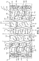
FIG. 3 schematically shows an enlarged orthogonal front view of another example tire tread in accordance with the present invention; and -
FIG. 4 schematically shows a section view of part of the tire tread ofFIG. 3 . - Examples of the present invention may be below described with reference to the accompanying drawings, wherein like reference numerals designate corresponding and/or identical elements throughout
FIGS. 1-4 . - As shown in
FIGS. 1-2 , an example non-pneumatic or pneumatic tire 1 according to the present invention (hereinafter may be referred to simply as "tire") may be a tire mounted in a designated direction on a vehicle. The right side of the tire 1 inFIG. 1 may be set as the outer side when it is mounted on a vehicle with the left side inFIG. 1 being the inner side. The tire 1 may be asymmetrical about a tire equator C. The tire 1 may be used for a passenger car, for example. - A
tread 2 of the tire 1 may have a pair ofshoulder grooves intermediate grooves 5, 6 (FIGS. 1 &3 ). Theshoulder grooves intermediate grooves - The
grooves center rib 11, a pair ofintermediate ribs shoulder ribs rib continuous grooves - The
tread elements 131 of the firstintermediate rib 13, separated by lateralintermediate grooves 133, may define a circumferential array of spaced apart angled lateral blind grooves orsipes 132 extending from thefirst shoulder groove 3 and toward the firstintermediate groove 5. Thecontinuous center rib 11 may have a circumferential array of alternating lateralstraight grooves 111 and lateral S-shapedgrooves 112 extending from the firstintermediate groove 5 to the secondintermediate groove 6. Thetread elements 151 of the secondintermediate rib 15, separated by lateralintermediate grooves 153, may define a circumferential array of spaced apart angled lateral blind grooves orsipes 152 extending toward the secondintermediate groove 6 and toward thesecond shoulder groove 4. - The
first shoulder rib 17 may include a plurality of axiallyouter shoulder elements 171 and corresponding axially adjacent and axiallyinner shoulder elements 172. The axiallyouter shoulder elements 171 and axiallyinner shoulder elements 172 may be axially separated bycircumferential grooves 177. Theouter shoulder elements 171 may extend axially outward to and over the tread edge Te and be circumferentially separated bylateral shoulder grooves 173. The axiallyouter shoulder elements 171 may each have a pair of angled lateral S-shaped blind grooves orsipes 178 extending axially away from theinner shoulder elements 172. Any or all of the S-shaped blind grooves orsipes 178 may have a straight circumferential groove orsipe 179 extending circumferentially to one of thelateral shoulder grooves 173. - The axially
inner shoulder elements 172, also circumferentially separated by thelateral shoulder grooves 173, may each define two spaced apart angled lateral S-shaped blind grooves orsipes 174 extending axially outward from thefirst shoulder groove 3. The S-shaped blind grooves orsipes 174 may each have a straight circumferential groove orsipe 175 extending circumferentially to one of thelateral shoulder grooves 173. - The
second shoulder rib 19 may include a plurality of axiallyouter shoulder elements 191 and corresponding axially adjacent and axiallyinner shoulder elements 192. The axiallyouter shoulder elements 191 and axiallyinner shoulder elements 192 may be axially separated bycircumferential grooves 197. Theouter shoulder elements 191 may extend axially outward to and over the tread edge Te and be circumferentially separated bylateral shoulder grooves 193. The axiallyouter shoulder elements 191 may each have a pair of angled lateral S-shaped blind grooves orsipes 198 extending axially away from theinner shoulder elements 192. Any or all of the S-shaped blind grooves orsipes 198 may have a straight circumferential groove orsipe 199 extending circumferentially to one of thelateral shoulder grooves 193, similar to the circumferential grooves orsipes 179 of thefirst shoulder rib 17. - The axially
inner shoulder elements 192, also circumferentially separated by thelateral shoulder grooves 193, may each define two spaced apart angled lateral S-shaped blind grooves orsipes 194 extending axially outward from thesecond shoulder groove 4. The S-shaped blind grooves orsipes 194 may each have a straight circumferential groove orsipe 195 extending circumferentially to one of thelateral shoulder grooves 193. - As shown in
FIGS. 3-4 , another example non-pneumatic or pneumatic tire 1 according to the present invention (hereinafter may be referred to simply as "tire") may be a tire mounted in a designated direction on a vehicle. The right side of the tire 1 inFIG. 3 may be set as the outer side when it is mounted on a vehicle with the left side inFIG. 3 being the inner side. The tire 1 may be asymmetrical about a tire equator C. The tire 1 may be used for a passenger car, for example. - As in
FIGS. 1-2 , the axiallyouter shoulder elements 171 ofFIGS. 3-4 may have a pair of angled lateral S-shaped blind grooves orsipes 178 extending axially away from theinner shoulder elements 172. Any or all of the S-shaped blind grooves orsipes 178 may form or be joint with a L-shaped groove orsipe 278 with a straight portion extending circumferentially to one of thelateral shoulder grooves 173. The axiallyinner shoulder elements 172, also circumferentially separated by thelateral shoulder grooves 173, may each define two spaced apart L-shaped grooves orsipes 279 extending axially and circumferentially. The L-shaped grooves orsipes 279 may each have a straight portion extending circumferentially to one of thelateral shoulder grooves 173. - Again, as in
FIGS. 1-2 , the axiallyouter shoulder elements 191 ofFIGS. 3-4 may have a pair of angled lateral S-shaped blind grooves orsipes 198 extending axially away from theinner shoulder elements 192. Any or all of the S-shaped blind grooves or sipes may form or be joint with a L-shapedsipe 298 with a straight portion extending circumferentially to one of thelateral shoulder grooves 193. The axiallyinner shoulder elements 192, also circumferentially separated by thelateral shoulder grooves 193, may each define two spaced apart L-shaped grooves orsipes 299 extending axially and circumferentially. The L-shaped grooves orsipes 298 may each have a straight portion extending circumferentially to one of thelateral shoulder grooves 173.
Claims (15)
- A tire tread comprising a plurality of circumferential grooves (3, 4, 5, 6), each of the plurality of circumferential grooves (3, 4, 5, 6) extending continuously in a tire circumferential direction, the plurality of circumferential grooves (3, 4, 5, 6) comprising a first circumferential shoulder groove (3) limiting a first circumferentially extending shoulder rib (17) on the axially inner side of the shoulder rib (17), the first shoulder rib (17) having a plurality of first shoulder elements, each first shoulder element being limited by two lateral shoulder grooves (173) and each first shoulder element having an axially outer first shoulder element (171) and a corresponding axially adjacent and axially inner first shoulder element (172) separated by a circumferential groove (177), the axially outer first shoulder elements (171) each having a pair of angled outer lateral S-shaped blind grooves or sipes (178) extending axially away from the inner first shoulder elements (172).
- The tire tread of claim 1 wherein the tire tread further comprises a second circumferential shoulder groove (3) limiting a second circumferentially extending shoulder rib (19) on the axially inner side of the shoulder rib (19), the second shoulder rib (19) having a plurality of second shoulder elements, each second shoulder element being limited by two lateral shoulder grooves (193) and each second shoulder element having an axially outer second shoulder element (191) and a corresponding axially adjacent and axially inner second shoulder element (192) separated by a circumferential groove (197), the axially outer second shoulder elements (191) each having a pair of angled outer lateral S-shaped blind grooves or sipes (198) extending axially away from the inner second shoulder elements (192).
- The tire tread of claim 1 or 2 wherein each of the outer lateral S-shaped blind grooves or sipes (178) of the axially outer first shoulder elements (171) is joint with a straight circumferential groove or sipe (179) extending circumferentially to a lateral shoulder groove (173).
- The tire tread of at least one of the previous claims wherein each of the outer lateral S-shaped blind grooves or sipes (198) of the axially outer second shoulder elements (191) is joint with a straight circumferential groove or sipe (199) extending circumferentially to a lateral shoulder groove (193).
- The tire tread of at least one of the previous claims wherein the axially inner first shoulder elements (172) each have two spaced apart inner lateral S-shaped blind grooves or sipes (174) extending axially outward from the respective circumferential shoulder groove (3, 5).
- The tire tread of claim 5 wherein each said inner lateral S-shaped blind groove or sipe (174) is joint with a straight circumferential groove or sipe extending circumferentially to a lateral shoulder groove (173).
- The tire tread of at least one of the previous claims wherein the axially inner second shoulder elements (192) each have two spaced apart inner lateral S-shaped blind grooves or sipes (194) extending axially outward from the respective circumferential shoulder groove (3, 5).
- The tire tread of claim 7 wherein each said inner lateral S-shaped blind groove or sipe (194) is joint with a straight circumferential groove or sipe extending circumferentially to a lateral shoulder groove (193).
- The tire tread of at least one of the previous claims wherein the axial widths of the circumferential grooves (3, 4, 5, 6) narrow as the circumferential grooves (3, 4, 5, 6) extend from a respective axially outer side of the tread (1) radially inward toward the tire tread equatorial plane (C).
- The tire tread of at least one of the previous claims wherein one or more or all of the axially inner first shoulder elements (172) define two spaced apart L-shaped grooves or sipes (279) extending axially and circumferentially, the L-shaped grooves or sipes (279) having a straight portion extending circumferentially to a lateral shoulder groove (173).
- The tire tread of at least one of the previous claims wherein one or more or all of the axially inner second shoulder elements (192) define two spaced apart L-shaped grooves or sipes (299) extending axially and circumferentially, the L-shaped grooves or sipes (299) having a straight portion extending circumferentially to a lateral shoulder groove (193).
- The tire tread of at least one of the previous claims having four circumferential grooves, namely said first and second circumferential shoulder grooves (3, 4) and a first and second intermediate circumferential groove (5, 6), the first and second intermediate circumferential groove (5, 6) defining a circumferentially extending center rib (11), the first circumferential shoulder groove (3) and the first intermediate circumferential groove (5) defining a circumferentially extending a first intermediate rib (13), and the second circumferential shoulder groove (4) and the second intermediate circumferential groove (6) defining a circumferentially extending a second intermediate rib (15).
- The tire of claim 12 wherein said circumferentially extending center rib (11) comprises laterally extending sipes or grooves (111, 112).
- The tire of claim 13 wherein said circumferentially extending center rib (11) comprises laterally extending circumferentially alternating straight and S-shaped sipes or grooves (111, 112).
- A tire having a tread (2) in accordance with at least one of the previous claims.
Applications Claiming Priority (1)
| Application Number | Priority Date | Filing Date | Title |
|---|---|---|---|
| US17/308,192 US12420591B2 (en) | 2021-05-05 | 2021-05-05 | Tire tread |
Publications (1)
| Publication Number | Publication Date |
|---|---|
| EP4086087A1 true EP4086087A1 (en) | 2022-11-09 |
Family
ID=81392791
Family Applications (1)
| Application Number | Title | Priority Date | Filing Date |
|---|---|---|---|
| EP22170552.8A Withdrawn EP4086087A1 (en) | 2021-05-05 | 2022-04-28 | Tire tread and tire |
Country Status (3)
| Country | Link |
|---|---|
| US (1) | US12420591B2 (en) |
| EP (1) | EP4086087A1 (en) |
| CN (1) | CN115302987B (en) |
Families Citing this family (1)
| Publication number | Priority date | Publication date | Assignee | Title |
|---|---|---|---|---|
| JP2024097520A (en) * | 2023-01-06 | 2024-07-19 | Toyo Tire株式会社 | Pneumatic tires |
Citations (6)
| Publication number | Priority date | Publication date | Assignee | Title |
|---|---|---|---|---|
| JPH07290908A (en) * | 1994-04-28 | 1995-11-07 | Toyo Tire & Rubber Co Ltd | studless tire |
| US20140360639A1 (en) * | 2013-06-10 | 2014-12-11 | Toyo Tire & Rubber Co., Ltd. | Pneumatic tire |
| EP3375643A1 (en) * | 2015-11-12 | 2018-09-19 | Bridgestone Corporation | Tire |
| JP2019131152A (en) * | 2018-02-02 | 2019-08-08 | 横浜ゴム株式会社 | Pneumatic tire |
| JP2019151151A (en) * | 2018-02-28 | 2019-09-12 | 横浜ゴム株式会社 | Pneumatic tire |
| US20200298627A1 (en) * | 2019-03-18 | 2020-09-24 | Toyo Tire Corporation | Pneumatic tire |
Family Cites Families (39)
| Publication number | Priority date | Publication date | Assignee | Title |
|---|---|---|---|---|
| JPH0443104A (en) | 1990-06-11 | 1992-02-13 | Bridgestone Corp | Tire for new traffic vehicle |
| JP3380605B2 (en) | 1993-05-20 | 2003-02-24 | 株式会社ブリヂストン | Pneumatic tire |
| AT402178B (en) * | 1994-02-25 | 1997-02-25 | Semperit Ag | TIRE TIRE FOR A VEHICLE AIR TIRE |
| JP2905704B2 (en) | 1994-09-28 | 1999-06-14 | 住友ゴム工業株式会社 | Heavy duty pneumatic tires |
| US5833780A (en) | 1995-06-21 | 1998-11-10 | The Yokohama Rubber Co., Ltd. | Pneumatic radial tire for heavy loads |
| JP3079026B2 (en) | 1995-11-15 | 2000-08-21 | 住友ゴム工業株式会社 | studless tire |
| JPH09156316A (en) * | 1995-12-04 | 1997-06-17 | Yokohama Rubber Co Ltd:The | Pneumatic radial tire |
| JP3717617B2 (en) | 1996-02-02 | 2005-11-16 | 株式会社ブリヂストン | Pneumatic radial tire |
| JP3515296B2 (en) | 1996-10-28 | 2004-04-05 | 横浜ゴム株式会社 | Heavy duty pneumatic tires |
| DE19753819B4 (en) * | 1997-12-04 | 2004-04-01 | Continental Aktiengesellschaft | Tread pattern of a winter tire |
| US6102092A (en) | 1998-06-17 | 2000-08-15 | Michelin Recherche Et Technique S.A. | Tire having sacrificial bridging |
| KR100839139B1 (en) | 1998-10-30 | 2008-06-19 | 피렐리 타이어 소시에떼 퍼 아찌오니 | Motor vehicle tires, especially for trucks and vans |
| US6467517B1 (en) | 1999-06-15 | 2002-10-22 | Michelin Recherche Et Technique S.A. | Tire having sacrificial bridging |
| US20020092591A1 (en) * | 2001-01-17 | 2002-07-18 | Max Cortes | Tapered tire groove configuration |
| RU20485U1 (en) | 2001-07-10 | 2001-11-10 | Государственное унитарное предприятие "Научно-исследовательский институт шинной промышленности" | PNEUMATIC TIRE PROTECTOR |
| WO2004041556A1 (en) | 2002-11-06 | 2004-05-21 | Bridgestone Corporation | Pneumatic tire |
| JP4276614B2 (en) | 2004-11-25 | 2009-06-10 | 住友ゴム工業株式会社 | Pneumatic tire |
| JP4392339B2 (en) | 2004-12-24 | 2009-12-24 | 住友ゴム工業株式会社 | Pneumatic tire |
| JP2007216871A (en) | 2006-02-17 | 2007-08-30 | Bridgestone Corp | Pneumatic tire |
| JP4406455B2 (en) | 2007-12-18 | 2010-01-27 | 住友ゴム工業株式会社 | Pneumatic tire |
| JP5311841B2 (en) | 2008-02-19 | 2013-10-09 | 株式会社ブリヂストン | Pneumatic tire |
| USD610068S1 (en) | 2008-07-24 | 2010-02-16 | Sumitomo Rubber Industries, Ltd. | Tire for automobile |
| JP4755709B2 (en) | 2009-08-03 | 2011-08-24 | 住友ゴム工業株式会社 | Pneumatic tire |
| FR2955289B1 (en) | 2010-01-19 | 2012-01-27 | Soc Tech Michelin | TIRE TREAD COMPRISING AN IMPROVED NOISE REDUCING DEVICE |
| JP5185983B2 (en) | 2010-08-10 | 2013-04-17 | 住友ゴム工業株式会社 | Heavy duty pneumatic tire |
| JP5250016B2 (en) * | 2010-11-12 | 2013-07-31 | 住友ゴム工業株式会社 | Pneumatic tire |
| FR2968242B1 (en) | 2010-12-02 | 2013-01-04 | Michelin Soc Tech | ANTI-NOISE DEVICE FOR BEING REPORTED IN A BEARING OF THE BEARING BAND OF A PNEUMATIC AND TIRE COMPRISING A DEVICE OF THIS TYPE. |
| JP5852608B2 (en) | 2013-01-28 | 2016-02-03 | 住友ゴム工業株式会社 | Pneumatic tire |
| JP5873457B2 (en) | 2013-04-12 | 2016-03-01 | 住友ゴム工業株式会社 | Pneumatic tire |
| US20180072104A1 (en) * | 2014-03-07 | 2018-03-15 | Bridgestone Americas Tire Operations, Llc | Tire tread featuring a sipe |
| JP6412461B2 (en) * | 2015-04-15 | 2018-10-24 | 株式会社ブリヂストン | Run flat tire |
| EP3375640B1 (en) * | 2015-11-12 | 2020-10-07 | Bridgestone Corporation | Tire |
| JP6711171B2 (en) * | 2016-06-27 | 2020-06-17 | 住友ゴム工業株式会社 | tire |
| JP6885176B2 (en) | 2017-04-18 | 2021-06-09 | 住友ゴム工業株式会社 | tire |
| US10807416B2 (en) | 2018-02-23 | 2020-10-20 | The Goodyear Tire & Rubber Company | Tire tread |
| JP7035740B2 (en) * | 2018-04-06 | 2022-03-15 | 住友ゴム工業株式会社 | tire |
| USD937187S1 (en) * | 2019-12-04 | 2021-11-30 | The Goodyear Tire & Rubber Company | Tire |
| JP7431573B2 (en) * | 2019-12-19 | 2024-02-15 | 株式会社ブリヂストン | tire |
| USD944187S1 (en) * | 2020-05-27 | 2022-02-22 | The Goodyear Tire & Rubber Company | Tire |
-
2021
- 2021-05-05 US US17/308,192 patent/US12420591B2/en active Active
-
2022
- 2022-04-28 EP EP22170552.8A patent/EP4086087A1/en not_active Withdrawn
- 2022-05-05 CN CN202210480729.8A patent/CN115302987B/en active Active
Patent Citations (6)
| Publication number | Priority date | Publication date | Assignee | Title |
|---|---|---|---|---|
| JPH07290908A (en) * | 1994-04-28 | 1995-11-07 | Toyo Tire & Rubber Co Ltd | studless tire |
| US20140360639A1 (en) * | 2013-06-10 | 2014-12-11 | Toyo Tire & Rubber Co., Ltd. | Pneumatic tire |
| EP3375643A1 (en) * | 2015-11-12 | 2018-09-19 | Bridgestone Corporation | Tire |
| JP2019131152A (en) * | 2018-02-02 | 2019-08-08 | 横浜ゴム株式会社 | Pneumatic tire |
| JP2019151151A (en) * | 2018-02-28 | 2019-09-12 | 横浜ゴム株式会社 | Pneumatic tire |
| US20200298627A1 (en) * | 2019-03-18 | 2020-09-24 | Toyo Tire Corporation | Pneumatic tire |
Also Published As
| Publication number | Publication date |
|---|---|
| CN115302987A (en) | 2022-11-08 |
| US12420591B2 (en) | 2025-09-23 |
| CN115302987B (en) | 2025-05-30 |
| US20220355622A1 (en) | 2022-11-10 |
Similar Documents
| Publication | Publication Date | Title |
|---|---|---|
| EP1987965B1 (en) | Pneumatic tire | |
| EP3656580B1 (en) | Pneumatic tire | |
| EP3496958B1 (en) | Apparatuses and methods for improving chunking and cracking resistance of tires | |
| EP1995080B1 (en) | Pneumatic tire | |
| KR101101042B1 (en) | Tread for pneumatic tires | |
| EP3521067B1 (en) | Tread for a tire | |
| JP5443923B2 (en) | Pneumatic tire | |
| EP1008465A2 (en) | Vehicle tyre | |
| EP1935671A2 (en) | Pneumatic tire | |
| EP0282252B1 (en) | Radial tyre | |
| EP1935670B1 (en) | Pneumatic tire | |
| CN112124008B (en) | pneumatic tire | |
| EP3368351B1 (en) | Twisted sipes | |
| EP3444129A1 (en) | Pneumatic tire | |
| RU2531435C2 (en) | Winter tire | |
| EP3666551A1 (en) | Tire tread | |
| WO2017141912A1 (en) | Pneumatic tire | |
| EP3670209B1 (en) | Tread for a pneumatic tire | |
| EP4265442B1 (en) | TIRE | |
| US12420591B2 (en) | Tire tread | |
| EP3530489A1 (en) | Tire tread | |
| US20200101796A1 (en) | Snow vice channels | |
| EP4438336A1 (en) | Tire with an improved tread pattern | |
| US12409684B2 (en) | Bi-directional sipe and/or slot | |
| US11807045B2 (en) | Tire with hybrid sipe pattern |
Legal Events
| Date | Code | Title | Description |
|---|---|---|---|
| PUAI | Public reference made under article 153(3) epc to a published international application that has entered the european phase |
Free format text: ORIGINAL CODE: 0009012 |
|
| STAA | Information on the status of an ep patent application or granted ep patent |
Free format text: STATUS: THE APPLICATION HAS BEEN PUBLISHED |
|
| AK | Designated contracting states |
Kind code of ref document: A1 Designated state(s): AL AT BE BG CH CY CZ DE DK EE ES FI FR GB GR HR HU IE IS IT LI LT LU LV MC MK MT NL NO PL PT RO RS SE SI SK SM TR |
|
| STAA | Information on the status of an ep patent application or granted ep patent |
Free format text: STATUS: REQUEST FOR EXAMINATION WAS MADE |
|
| 17P | Request for examination filed |
Effective date: 20230509 |
|
| RBV | Designated contracting states (corrected) |
Designated state(s): AL AT BE BG CH CY CZ DE DK EE ES FI FR GB GR HR HU IE IS IT LI LT LU LV MC MK MT NL NO PL PT RO RS SE SI SK SM TR |
|
| GRAP | Despatch of communication of intention to grant a patent |
Free format text: ORIGINAL CODE: EPIDOSNIGR1 |
|
| STAA | Information on the status of an ep patent application or granted ep patent |
Free format text: STATUS: GRANT OF PATENT IS INTENDED |
|
| INTG | Intention to grant announced |
Effective date: 20240125 |
|
| STAA | Information on the status of an ep patent application or granted ep patent |
Free format text: STATUS: THE APPLICATION IS DEEMED TO BE WITHDRAWN |
|
| 18D | Application deemed to be withdrawn |
Effective date: 20240528 |