EP3530489A1 - Tire tread - Google Patents
Tire tread Download PDFInfo
- Publication number
- EP3530489A1 EP3530489A1 EP19156335.2A EP19156335A EP3530489A1 EP 3530489 A1 EP3530489 A1 EP 3530489A1 EP 19156335 A EP19156335 A EP 19156335A EP 3530489 A1 EP3530489 A1 EP 3530489A1
- Authority
- EP
- European Patent Office
- Prior art keywords
- groove
- curtain
- tire
- axial width
- tread
- Prior art date
- Legal status (The legal status is an assumption and is not a legal conclusion. Google has not performed a legal analysis and makes no representation as to the accuracy of the status listed.)
- Withdrawn
Links
Images

Classifications
-
- B—PERFORMING OPERATIONS; TRANSPORTING
- B60—VEHICLES IN GENERAL
- B60C—VEHICLE TYRES; TYRE INFLATION; TYRE CHANGING; CONNECTING VALVES TO INFLATABLE ELASTIC BODIES IN GENERAL; DEVICES OR ARRANGEMENTS RELATED TO TYRES
- B60C11/00—Tyre tread bands; Tread patterns; Anti-skid inserts
- B60C11/03—Tread patterns
- B60C11/0304—Asymmetric patterns
-
- B—PERFORMING OPERATIONS; TRANSPORTING
- B60—VEHICLES IN GENERAL
- B60C—VEHICLE TYRES; TYRE INFLATION; TYRE CHANGING; CONNECTING VALVES TO INFLATABLE ELASTIC BODIES IN GENERAL; DEVICES OR ARRANGEMENTS RELATED TO TYRES
- B60C11/00—Tyre tread bands; Tread patterns; Anti-skid inserts
- B60C11/03—Tread patterns
- B60C11/0302—Tread patterns directional pattern, i.e. with main rolling direction
-
- B—PERFORMING OPERATIONS; TRANSPORTING
- B60—VEHICLES IN GENERAL
- B60C—VEHICLE TYRES; TYRE INFLATION; TYRE CHANGING; CONNECTING VALVES TO INFLATABLE ELASTIC BODIES IN GENERAL; DEVICES OR ARRANGEMENTS RELATED TO TYRES
- B60C11/00—Tyre tread bands; Tread patterns; Anti-skid inserts
- B60C11/03—Tread patterns
- B60C11/0306—Patterns comprising block rows or discontinuous ribs
- B60C11/0309—Patterns comprising block rows or discontinuous ribs further characterised by the groove cross-section
-
- B—PERFORMING OPERATIONS; TRANSPORTING
- B60—VEHICLES IN GENERAL
- B60C—VEHICLE TYRES; TYRE INFLATION; TYRE CHANGING; CONNECTING VALVES TO INFLATABLE ELASTIC BODIES IN GENERAL; DEVICES OR ARRANGEMENTS RELATED TO TYRES
- B60C11/00—Tyre tread bands; Tread patterns; Anti-skid inserts
- B60C11/03—Tread patterns
- B60C11/04—Tread patterns in which the raised area of the pattern consists only of continuous circumferential ribs, e.g. zig-zag
-
- B—PERFORMING OPERATIONS; TRANSPORTING
- B60—VEHICLES IN GENERAL
- B60C—VEHICLE TYRES; TYRE INFLATION; TYRE CHANGING; CONNECTING VALVES TO INFLATABLE ELASTIC BODIES IN GENERAL; DEVICES OR ARRANGEMENTS RELATED TO TYRES
- B60C11/00—Tyre tread bands; Tread patterns; Anti-skid inserts
- B60C11/03—Tread patterns
- B60C11/12—Tread patterns characterised by the use of narrow slits or incisions, e.g. sipes
-
- B—PERFORMING OPERATIONS; TRANSPORTING
- B60—VEHICLES IN GENERAL
- B60C—VEHICLE TYRES; TYRE INFLATION; TYRE CHANGING; CONNECTING VALVES TO INFLATABLE ELASTIC BODIES IN GENERAL; DEVICES OR ARRANGEMENTS RELATED TO TYRES
- B60C11/00—Tyre tread bands; Tread patterns; Anti-skid inserts
- B60C11/03—Tread patterns
- B60C11/13—Tread patterns characterised by the groove cross-section, e.g. for buttressing or preventing stone-trapping
- B60C11/1307—Tread patterns characterised by the groove cross-section, e.g. for buttressing or preventing stone-trapping with special features of the groove walls
- B60C11/1323—Tread patterns characterised by the groove cross-section, e.g. for buttressing or preventing stone-trapping with special features of the groove walls asymmetric
-
- B—PERFORMING OPERATIONS; TRANSPORTING
- B60—VEHICLES IN GENERAL
- B60C—VEHICLE TYRES; TYRE INFLATION; TYRE CHANGING; CONNECTING VALVES TO INFLATABLE ELASTIC BODIES IN GENERAL; DEVICES OR ARRANGEMENTS RELATED TO TYRES
- B60C11/00—Tyre tread bands; Tread patterns; Anti-skid inserts
- B60C11/03—Tread patterns
- B60C2011/0337—Tread patterns characterised by particular design features of the pattern
- B60C2011/0339—Grooves
- B60C2011/0341—Circumferential grooves
- B60C2011/0348—Narrow grooves, i.e. having a width of less than 4 mm
-
- B—PERFORMING OPERATIONS; TRANSPORTING
- B60—VEHICLES IN GENERAL
- B60C—VEHICLE TYRES; TYRE INFLATION; TYRE CHANGING; CONNECTING VALVES TO INFLATABLE ELASTIC BODIES IN GENERAL; DEVICES OR ARRANGEMENTS RELATED TO TYRES
- B60C11/00—Tyre tread bands; Tread patterns; Anti-skid inserts
- B60C11/03—Tread patterns
- B60C2011/0337—Tread patterns characterised by particular design features of the pattern
- B60C2011/0339—Grooves
- B60C2011/0341—Circumferential grooves
- B60C2011/0353—Circumferential grooves characterised by width
-
- B—PERFORMING OPERATIONS; TRANSPORTING
- B60—VEHICLES IN GENERAL
- B60C—VEHICLE TYRES; TYRE INFLATION; TYRE CHANGING; CONNECTING VALVES TO INFLATABLE ELASTIC BODIES IN GENERAL; DEVICES OR ARRANGEMENTS RELATED TO TYRES
- B60C11/00—Tyre tread bands; Tread patterns; Anti-skid inserts
- B60C11/03—Tread patterns
- B60C2011/0337—Tread patterns characterised by particular design features of the pattern
- B60C2011/0339—Grooves
- B60C2011/0381—Blind or isolated grooves
- B60C2011/0383—Blind or isolated grooves at the centre of the tread
-
- B—PERFORMING OPERATIONS; TRANSPORTING
- B60—VEHICLES IN GENERAL
- B60C—VEHICLE TYRES; TYRE INFLATION; TYRE CHANGING; CONNECTING VALVES TO INFLATABLE ELASTIC BODIES IN GENERAL; DEVICES OR ARRANGEMENTS RELATED TO TYRES
- B60C11/00—Tyre tread bands; Tread patterns; Anti-skid inserts
- B60C11/03—Tread patterns
- B60C2011/0337—Tread patterns characterised by particular design features of the pattern
- B60C2011/0386—Continuous ribs
- B60C2011/0388—Continuous ribs provided at the equatorial plane
-
- B—PERFORMING OPERATIONS; TRANSPORTING
- B60—VEHICLES IN GENERAL
- B60C—VEHICLE TYRES; TYRE INFLATION; TYRE CHANGING; CONNECTING VALVES TO INFLATABLE ELASTIC BODIES IN GENERAL; DEVICES OR ARRANGEMENTS RELATED TO TYRES
- B60C11/00—Tyre tread bands; Tread patterns; Anti-skid inserts
- B60C11/03—Tread patterns
- B60C2011/0337—Tread patterns characterised by particular design features of the pattern
- B60C2011/0386—Continuous ribs
- B60C2011/0393—Narrow ribs, i.e. having a rib width of less than 8 mm
-
- B—PERFORMING OPERATIONS; TRANSPORTING
- B60—VEHICLES IN GENERAL
- B60C—VEHICLE TYRES; TYRE INFLATION; TYRE CHANGING; CONNECTING VALVES TO INFLATABLE ELASTIC BODIES IN GENERAL; DEVICES OR ARRANGEMENTS RELATED TO TYRES
- B60C2200/00—Tyres specially adapted for particular applications
- B60C2200/04—Tyres specially adapted for particular applications for road vehicles, e.g. passenger cars
Abstract
A tire tread (2) is disclosed comprising a plurality of circumferential grooves (3, 5, 102) including a main circumferential groove (5). Each of the plurality of circumferential grooves (5, 6, 102) extends continuously in a tire circumferential direction when the tire tread (2) is used on a tire (1). The plurality of circumferential grooves (3, 5, 102) defines a circumferentially extending main rib (13) and a circumferentially extending curtain rib (101) axially separated by a curtain groove (102) from the circumferentially extending main rib (13). The main groove (5) is disposed axially opposite the curtain groove (102) and adjacent to the curtain rib (101). The curtain groove (102) has: (i) an axial width in a range of from 4% to 40% of a minimum axial width of the main groove (5) of the plurality of circumferential grooves (3, 5, 102); and/or (ii) an axial width in a range of from 0.5 to 1.5 mm. Also, a tire (1) having such a tread (2) is disclosed.
Description
- The present invention relates to a tire tread for use with pneumatic tire that exhibits excellent noise performance while maintaining wet performance.
- Conventionally, in addition to circumferential main grooves and lateral grooves, pneumatic tire treads may have sipes on a tread surface in order to demonstrate favorable functional characteristics (e.g., low noise generation, low rolling resistance, good traction, good durability, etc.).
- The invention relates to a tire tread in accordance with
claim 1 and to a tire in accordance withclaim 13. - Dependent claims refer to preferred embodiments of the invention.
- A tread in accordance with a preferred aspect of the present invention includes a plurality of circumferential grooves. Each of the plurality extends continuously in a tire circumferential direction. The plurality of circumferential grooves defining a circumferentially extending main rib and a circumferentially extending curtain rib axially separated by a curtain groove. The curtain groove having an axial width between 4% and 40% of a minimum axial width of a main groove of the plurality of circumferential grooves. The main groove is disposed axially opposite the curtain groove and adjacent to the curtain rib.
- According to another aspect preferred of the tread, the curtain groove has a radial depth less than or equal to the main groove.
- According to still another preferred aspect of the tread, the axial width of the curtain groove narrows as the curtain groove extends radially inward.
- According to yet another preferred aspect of the tread, the curtain rib has a uniform axial width between 0.5 mm and 3.5 mm.
- According to still another preferred aspect of the tread, the curtain rib has a uniform axial width of 2.0 mm.
- According to yet another preferred aspect of the tread, the main rib has a circumferential array of axially extending lateral grooves, the lateral grooves extending from one of the plurality of circumferential grooves other than the main groove.
- According to still another preferred aspect of the tread, one end of each of the lateral grooves joins the curtain groove.
- According to yet another preferred aspect of the tread, one end of the lateral grooves intersects with the curtain groove.
- According to still another preferred aspect of the tread, the curtain groove tapers radially inward to an axial width between 0.2 mm and 0.5 mm.
- According to yet another preferred aspect of the tread, the curtain groove tapers radially inward to an axial width less than an axial width of the curtain groove at an outer surface of the tread.
- A tire tread in accordance with another preferred aspect of the present invention includes a plurality of annular grooves. Each of the plurality extends continuously in a tire circumferential direction. The plurality of annular grooves defines a circumferentially extending main rib and a circumferentially extending curtain rib axially separated by a curtain groove. The curtain groove has an axial width between 4% and 10% of a minimum axial width of a main groove of the plurality of annular grooves. The main groove is located axially opposite the curtain groove and axially adjacent to the curtain rib.
- According to another preferred aspect of the tire tread, the curtain groove has a radial depth equal to the main groove.
- According to still another preferred aspect of the tire tread, the axial width of the curtain groove narrows as the curtain groove extends radially inward.
- According to yet another preferred aspect of the tire tread, the curtain rib has an axial width between 1.0 mm and 2.0 mm.
- According to still another preferred aspect of the tire tread, the curtain rib has an axial width of 1.0 mm.
- According to yet another preferred aspect of the tire tread, the main rib has a circumferential array of axially extending lateral grooves, the lateral grooves extending from one of the plurality of circumferential grooves other than the main groove.
- According to still another preferred aspect of the tire tread, one end of each of the lateral grooves joins the curtain groove.
- According to yet another preferred aspect of the tire tread, one end of the lateral grooves intersects with the curtain groove.
- According to still another preferred aspect of the tire tread, the curtain groove tapers radially inward to an axial width between 0.5 mm and 0.7 mm.
- According to yet another preferred aspect of the tire tread, the curtain groove tapers radially inward to an axial width less than an axial width of the curtain groove at an outer surface of the tread.
- A more complete appreciation of the present invention and many of the attendant advantages thereof will be readily ascertained as the same becomes better understood by reference to the following detailed description when considered in connection with the accompanying drawings, wherein:
-
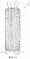
FIG. 1 schematically shows an orthogonal front view of an example tire tread in accordance with the present invention; -
FIG. 2 schematically shows a detail view of part of the tire tread ofFIG. 1 ; and -
FIG. 3 schematically shows a section view taken along line 3-3 inFIG. 2 . - Examples of the present invention may be below described with reference to the accompanying drawings, wherein like reference numerals designate corresponding and/or identical elements throughout
FIGS. 1-3 . - As shown in
FIGS. 1-2 , an example non-pneumatic orpneumatic tire 1 according to the present invention (hereinafter may be referred to simply as "tire") is a tire that can be mounted in a designated direction on a vehicle. The right side of thetire 1 inFIG. 1 is preferably set as the outer side when it is mounted on a vehicle. Thetire 1 is preferably asymmetrical about a tire equator C. Thetire 1 is preferably used for a passenger car, for example. - A
tread 2 oftire 1 preferably has a pair ofshoulder grooves intermediate grooves shoulder grooves intermediate grooves - The
grooves center rib 11, a pair ofintermediate ribs shoulder ribs rib continuous grooves - The
tread elements 131 of the firstintermediate rib 13 preferably define a circumferential array of spaced apart downwardly angledlateral grooves 132 extending from thefirst shoulder groove 3 toward the firstintermediate groove 5. - The
continuous center rib 11 preferably has a circumferential array of widely spaced apart downwardly angled blindlateral grooves 112 extending at a downward angle from the firstintermediate groove 5. - The continuous second
intermediate rib 15 preferably have a circumferential array of widely spaced apart shorter blindlateral grooves 152 extending from the secondintermediate groove 6. - The
tread elements 171 of thefirst shoulder rib 17 preferably define a circumferential array of downwardly archedlateral grooves 172 extending from the outer edge Te to thefirst shoulder groove 3. - The
tread elements 191 of thesecond shoulder rib 19 preferably define a circumferential array of upwardly arched lateral grooves 192 extending from the outer edge Te to thefirst shoulder groove 4. - Various
other sipes 9 may be located across theribs tread 2, as specifically shown inFIG. 2 . -
FIG. 3 shows a cross-sectional view taken at "3-3" inFIG. 2 . In accordance with the present invention, theexample tread 2 defines a circumferentially extending rib, orcurtain 101, coupled with one or more or all of theribs tire 1 under load. Thecurtain 101 may be coupled to therib example tire 1 andtread 2 ofFIGS. 1-3 , anarrow curtain 101 and the firstintermediate rib 13 are coupled by a narrowcircumferential curtain groove 102. In one embodiment, thecurtain 101 has the same radial height as the firstintermediate rib 13 and has a uniform axial width between 0.5 mm and 3.5 mm or 0.5 mm and 1.5 mm. The axial width of the of thecurtain groove 102 at anouter surface 103 of thetread 2 is preferably between 0.5 mm and 3.5 mm. - As the
curtain groove 102 extends radially inward, the axial width may lessen, or taper, to an axial width between 0.5 mm and 0.2 mm (FIG. 3 ). The radial depth of thecurtain groove 102 is preferably less than or equal to the radial depth of the firstintermediate groove 5 or the correspondingcircumferential groove - The
circumferential grooves - Thus, the axial width of the
curtain groove 102 may be between 4% and 20% or 4% and 40% the minimum axial width of the firstintermediate groove 5. - In one set of examples, the axial width of the
curtain groove 102 at theouter surface 103 of thetread 2 is 1.0 mm tapering to a 0.3 mm axial width at the radially innermost end of the curtain groove and the minimum axial width of the firstintermediate groove 5 may be 5.0 mm, 11.0 mm, or 7.0 mm. In these examples, the axial width of thecurtain groove 102 is 20%, 9%, or 14% of the minimum axial width of the firstintermediate groove 5. - In another set of examples, the axial width of the of the
curtain groove 102 at theouter surface 103 of thetread 2 is 1.0 mm tapering to a 0.3 mm axial width at the radially innermost end of the curtain groove and the minimum axial width of the firstintermediate groove 5 is 5.1 mm, 10.8 mm, or 6.7 mm. In these examples, the axial width of thecurtain groove 102 is approximately 20%, 9%, or 15% the minimum axial width of the firstintermediate groove 5. - In the example of
FIGS. 1-3 , thelateral grooves 132 of the firstintermediate rib 13 may extend and join thecurtain groove 102 in order to further suppress noise propagation. - The tread and tire in accordance with the invention shows reduced noise propagation and/or reduced airborne tread/tire noise. The example presented above of a
narrow curtain 101 and anarrow curtain groove 102 advantageously have very little, if any, effect on other tire characteristics, such as handling, wear, rolling resistance, and/or traction. The addition of thecurtain groove 102 also allows however to lessen tire weight and material costs.
Claims (15)
- A tire tread comprising a plurality of circumferential grooves (3, 5, 102) including a main circumferential groove (5), each of the plurality of circumferential grooves (5, 6, 102) extending continuously in a tire circumferential direction when the tire tread (2) is used on a tire (1), the plurality of circumferential grooves (3, 5, 102) defining a circumferentially extending main rib (13) and a circumferentially extending curtain rib (101) axially separated by a curtain groove (102) from the circumferentially extending main rib (13), the main groove (5) being disposed axially opposite the curtain groove (102) and adjacent to the curtain rib (101), the curtain groove (102) having: (i) an axial width in a range of from 4% to 40% of a minimum axial width of the main groove (5) of the plurality of circumferential grooves (3, 5, 102); and/or (ii) an axial width in a range of from 0.5 to 1.5 mm.
- The tire tread of claim 1 wherin the curtain groove (102) has an axial width in a range of from 4% to 20% of a minimum axial width of the main groove (5) of the plurality of circumferential grooves (3, 5, 102).
- The tire tread as set forth in claim 1 or 2 wherein the curtain groove (102) has a radial depth less than or equal to the radial depth of the main groove (5).
- The tire tread as set forth in at least one of the previous claims wherein the axial width of the curtain groove (102) narrows or tapers as the curtain groove (102) extends radially inward, preferably to an axial width in a range of from 0.5 mm to 0.2 mm.
- The tire tread as set forth in claim 1, 2 or 3 wherein the curtain rib (13) has a uniform axial width in a range of from 0.5 mm to 3.5 mm, preferably in a range of from 1 mm to 2 mm or of 2 mm.
- The tire tread as set forth in at least one of the previous claims wherein the main rib (13) has a circumferential array of axially extending lateral grooves (132), the lateral grooves (132) extending from one of the plurality of circumferential grooves (3, 5, 102) other than the main groove (5).
- The tire treed as set forth in claim 6 wherein one end of at least one or of each of the lateral grooves (132) joins the curtain groove (102).
- The tire tread as set forth in claim 6 or 7 wherein one end of at least one or of each the lateral grooves (132) intersects with the curtain groove (102).
- The tire tread as set forth in at least one of the previous claims wherein the curtain groove (102) tapers radially inward to an axial width less than an axial width of the curtain groove (102) at a radially outermost surface of the tread (2).
- The tire tread as set forth in at least one of the previous claims wherein the curtain groove (102) has a radial depth equal to a radial depth of the main groove (5).
- The tire tread as set forth in at least one of the previous claims wherein the curtain rib (101) has an axial width in a range of from 1.0 mm to 3.0 mm or of 1 mm.
- The tire tread as set forth in at least one of the previous claims wherein the axial width of the curtain groove (102) narrows or tapers as the curtain groove (102) extends radially inward to an axial width in a range of from 0.5 mm to 0.7 mm.
- A pneumatic tire having a tread (2) in accordance with at least one of the previous claims.
- The pneumatic tire of claim 13, wherein the tire (1) is a passenger tire.
- The pneumatic tire of claim 13 or 14, wherein the tire (1) has an asymmetric tread pattern with respect to the equatorial plane (C) of the tire (1).
Applications Claiming Priority (1)
| Application Number | Priority Date | Filing Date | Title |
|---|---|---|---|
| US15/903,060 US10807416B2 (en) | 2018-02-23 | 2018-02-23 | Tire tread |
Publications (1)
| Publication Number | Publication Date |
|---|---|
| EP3530489A1 true EP3530489A1 (en) | 2019-08-28 |
Family
ID=65408909
Family Applications (1)
| Application Number | Title | Priority Date | Filing Date |
|---|---|---|---|
| EP19156335.2A Withdrawn EP3530489A1 (en) | 2018-02-23 | 2019-02-11 | Tire tread |
Country Status (2)
| Country | Link |
|---|---|
| US (1) | US10807416B2 (en) |
| EP (1) | EP3530489A1 (en) |
Citations (5)
| Publication number | Priority date | Publication date | Assignee | Title |
|---|---|---|---|---|
| US5665184A (en) * | 1994-09-28 | 1997-09-09 | Sumitomo Rubber Industries, Ltd. | Heavy duty pneumatic tire |
| US5833780A (en) * | 1995-06-21 | 1998-11-10 | The Yokohama Rubber Co., Ltd. | Pneumatic radial tire for heavy loads |
| US5891276A (en) * | 1996-10-28 | 1999-04-06 | The Yokohama Rubber Co., Ltd. | Pneumatic tire for heavy duty including narrow block |
| JP2009149124A (en) * | 2007-12-18 | 2009-07-09 | Sumitomo Rubber Ind Ltd | Pneumatic tire |
| EP2281698A1 (en) * | 2009-08-03 | 2011-02-09 | Sumitomo Rubber Industries, Ltd. | Pneumatic tire |
Family Cites Families (16)
| Publication number | Priority date | Publication date | Assignee | Title |
|---|---|---|---|---|
| JPH0443104A (en) * | 1990-06-11 | 1992-02-13 | Bridgestone Corp | Tire for new traffic vehicle |
| JP3380605B2 (en) | 1993-05-20 | 2003-02-24 | 株式会社ブリヂストン | Pneumatic tire |
| JP3079026B2 (en) | 1995-11-15 | 2000-08-21 | 住友ゴム工業株式会社 | studless tire |
| JP3717617B2 (en) * | 1996-02-02 | 2005-11-16 | 株式会社ブリヂストン | Pneumatic radial tire |
| US6102092A (en) | 1998-06-17 | 2000-08-15 | Michelin Recherche Et Technique S.A. | Tire having sacrificial bridging |
| KR100839139B1 (en) | 1998-10-30 | 2008-06-19 | 피렐리 타이어 소시에떼 퍼 아찌오니 | Motor Vehicle Tyre, Particularly For Lorries And The Like |
| US6467517B1 (en) | 1999-06-15 | 2002-10-22 | Michelin Recherche Et Technique S.A. | Tire having sacrificial bridging |
| JP4295728B2 (en) | 2002-11-06 | 2009-07-15 | 株式会社ブリヂストン | Pneumatic tire |
| JP4276614B2 (en) | 2004-11-25 | 2009-06-10 | 住友ゴム工業株式会社 | Pneumatic tire |
| JP4392339B2 (en) | 2004-12-24 | 2009-12-24 | 住友ゴム工業株式会社 | Pneumatic tire |
| JP5311841B2 (en) | 2008-02-19 | 2013-10-09 | 株式会社ブリヂストン | Pneumatic tire |
| USD610068S1 (en) | 2008-07-24 | 2010-02-16 | Sumitomo Rubber Industries, Ltd. | Tire for automobile |
| FR2955289B1 (en) | 2010-01-19 | 2012-01-27 | Soc Tech Michelin | TIRE TREAD COMPRISING AN IMPROVED NOISE REDUCING DEVICE |
| JP5185983B2 (en) * | 2010-08-10 | 2013-04-17 | 住友ゴム工業株式会社 | Heavy duty pneumatic tire |
| FR2968242B1 (en) | 2010-12-02 | 2013-01-04 | Michelin Soc Tech | ANTI-NOISE DEVICE FOR BEING REPORTED IN A BEARING OF THE BEARING BAND OF A PNEUMATIC AND TIRE COMPRISING A DEVICE OF THIS TYPE. |
| JP5873457B2 (en) | 2013-04-12 | 2016-03-01 | 住友ゴム工業株式会社 | Pneumatic tire |
-
2018
- 2018-02-23 US US15/903,060 patent/US10807416B2/en active Active
-
2019
- 2019-02-11 EP EP19156335.2A patent/EP3530489A1/en not_active Withdrawn
Patent Citations (5)
| Publication number | Priority date | Publication date | Assignee | Title |
|---|---|---|---|---|
| US5665184A (en) * | 1994-09-28 | 1997-09-09 | Sumitomo Rubber Industries, Ltd. | Heavy duty pneumatic tire |
| US5833780A (en) * | 1995-06-21 | 1998-11-10 | The Yokohama Rubber Co., Ltd. | Pneumatic radial tire for heavy loads |
| US5891276A (en) * | 1996-10-28 | 1999-04-06 | The Yokohama Rubber Co., Ltd. | Pneumatic tire for heavy duty including narrow block |
| JP2009149124A (en) * | 2007-12-18 | 2009-07-09 | Sumitomo Rubber Ind Ltd | Pneumatic tire |
| EP2281698A1 (en) * | 2009-08-03 | 2011-02-09 | Sumitomo Rubber Industries, Ltd. | Pneumatic tire |
Also Published As
| Publication number | Publication date |
|---|---|
| US20190263186A1 (en) | 2019-08-29 |
| US10807416B2 (en) | 2020-10-20 |
Similar Documents
| Publication | Publication Date | Title |
|---|---|---|
| EP3397512B1 (en) | A tyre for vehicle wheels | |
| US8550133B2 (en) | Pneumatic tire with asymmetric tread pattern | |
| US5240053A (en) | Tire tread with spaced central tread narrow grooves | |
| JP5971280B2 (en) | Pneumatic tire | |
| US20170100965A1 (en) | Tire | |
| EP1987965B1 (en) | Pneumatic tire | |
| EP3621823B1 (en) | Tyre for vehicle wheels | |
| JP5200520B2 (en) | Pneumatic tire | |
| EP3498497B1 (en) | Tyre | |
| EP1498290B1 (en) | Tire tread | |
| EP1995080A2 (en) | Pneumatic tire | |
| US20050241738A1 (en) | Pneumatic tire | |
| WO2018150746A1 (en) | Pneumatic tire | |
| US11148472B2 (en) | Tyre | |
| CN107667017A (en) | Tire tread | |
| EP0282252A2 (en) | Radial tyre | |
| US10427468B2 (en) | Pneumatic tire | |
| US20170210177A1 (en) | Pneumatic tire | |
| EP3530489A1 (en) | Tire tread | |
| JP6411947B2 (en) | tire | |
| CN111433050B (en) | Pneumatic tire for vehicle | |
| EP3444129A1 (en) | Pneumatic tire | |
| US20190054770A1 (en) | Off the road tire | |
| JP2000043514A (en) | Pneumatic tire | |
| EP3670209B1 (en) | Tread for a pneumatic tire |
Legal Events
| Date | Code | Title | Description |
|---|---|---|---|
| PUAI | Public reference made under article 153(3) epc to a published international application that has entered the european phase |
Free format text: ORIGINAL CODE: 0009012 |
|
| AK | Designated contracting states |
Kind code of ref document: A1 Designated state(s): AL AT BE BG CH CY CZ DE DK EE ES FI FR GB GR HR HU IE IS IT LI LT LU LV MC MK MT NL NO PL PT RO RS SE SI SK SM TR |
|
| AX | Request for extension of the european patent |
Extension state: BA ME |
|
| STAA | Information on the status of an ep patent application or granted ep patent |
Free format text: STATUS: THE APPLICATION IS DEEMED TO BE WITHDRAWN |
|
| 18D | Application deemed to be withdrawn |
Effective date: 20200229 |