EP4086007A1 - Düse zur erzeugung von einem pulsierenden flüssigkeitsstrahl - Google Patents
Düse zur erzeugung von einem pulsierenden flüssigkeitsstrahl Download PDFInfo
- Publication number
- EP4086007A1 EP4086007A1 EP21172887.8A EP21172887A EP4086007A1 EP 4086007 A1 EP4086007 A1 EP 4086007A1 EP 21172887 A EP21172887 A EP 21172887A EP 4086007 A1 EP4086007 A1 EP 4086007A1
- Authority
- EP
- European Patent Office
- Prior art keywords
- nozzle
- splitter
- outlet
- shell
- fluid
- Prior art date
- Legal status (The legal status is an assumption and is not a legal conclusion. Google has not performed a legal analysis and makes no representation as to the accuracy of the status listed.)
- Withdrawn
Links
Images



Classifications
-
- A—HUMAN NECESSITIES
- A61—MEDICAL OR VETERINARY SCIENCE; HYGIENE
- A61C—DENTISTRY; APPARATUS OR METHODS FOR ORAL OR DENTAL HYGIENE
- A61C17/00—Devices for cleaning, polishing, rinsing or drying teeth, teeth cavities or prostheses; Saliva removers; Dental appliances for receiving spittle
- A61C17/02—Rinsing or air-blowing devices, e.g. using fluid jets or comprising liquid medication
-
- B—PERFORMING OPERATIONS; TRANSPORTING
- B05—SPRAYING OR ATOMISING IN GENERAL; APPLYING FLUENT MATERIALS TO SURFACES, IN GENERAL
- B05B—SPRAYING APPARATUS; ATOMISING APPARATUS; NOZZLES
- B05B3/00—Spraying or sprinkling apparatus with moving outlet elements or moving deflecting elements
- B05B3/02—Spraying or sprinkling apparatus with moving outlet elements or moving deflecting elements with rotating elements
- B05B3/04—Spraying or sprinkling apparatus with moving outlet elements or moving deflecting elements with rotating elements driven by the liquid or other fluent material discharged, e.g. the liquid actuating a motor before passing to the outlet
- B05B3/0417—Spraying or sprinkling apparatus with moving outlet elements or moving deflecting elements with rotating elements driven by the liquid or other fluent material discharged, e.g. the liquid actuating a motor before passing to the outlet comprising a liquid driven rotor, e.g. a turbine
- B05B3/0446—Spraying or sprinkling apparatus with moving outlet elements or moving deflecting elements with rotating elements driven by the liquid or other fluent material discharged, e.g. the liquid actuating a motor before passing to the outlet comprising a liquid driven rotor, e.g. a turbine with automatic means for regulating the discharged jet
-
- B—PERFORMING OPERATIONS; TRANSPORTING
- B05—SPRAYING OR ATOMISING IN GENERAL; APPLYING FLUENT MATERIALS TO SURFACES, IN GENERAL
- B05B—SPRAYING APPARATUS; ATOMISING APPARATUS; NOZZLES
- B05B1/00—Nozzles, spray heads or other outlets, with or without auxiliary devices such as valves, heating means
- B05B1/02—Nozzles, spray heads or other outlets, with or without auxiliary devices such as valves, heating means designed to produce a jet, spray, or other discharge of particular shape or nature, e.g. in single drops, or having an outlet of particular shape
- B05B1/08—Nozzles, spray heads or other outlets, with or without auxiliary devices such as valves, heating means designed to produce a jet, spray, or other discharge of particular shape or nature, e.g. in single drops, or having an outlet of particular shape of pulsating nature, e.g. delivering liquid in successive separate quantities
- B05B1/083—Nozzles, spray heads or other outlets, with or without auxiliary devices such as valves, heating means designed to produce a jet, spray, or other discharge of particular shape or nature, e.g. in single drops, or having an outlet of particular shape of pulsating nature, e.g. delivering liquid in successive separate quantities the pulsating mechanism comprising movable parts
- B05B1/085—Nozzles, spray heads or other outlets, with or without auxiliary devices such as valves, heating means designed to produce a jet, spray, or other discharge of particular shape or nature, e.g. in single drops, or having an outlet of particular shape of pulsating nature, e.g. delivering liquid in successive separate quantities the pulsating mechanism comprising movable parts rotated by the liquid or other fluent material discharged, e.g. liquid rotated turbines
-
- B—PERFORMING OPERATIONS; TRANSPORTING
- B05—SPRAYING OR ATOMISING IN GENERAL; APPLYING FLUENT MATERIALS TO SURFACES, IN GENERAL
- B05B—SPRAYING APPARATUS; ATOMISING APPARATUS; NOZZLES
- B05B3/00—Spraying or sprinkling apparatus with moving outlet elements or moving deflecting elements
- B05B3/14—Spraying or sprinkling apparatus with moving outlet elements or moving deflecting elements with oscillating elements; with intermittent operation
- B05B3/16—Spraying or sprinkling apparatus with moving outlet elements or moving deflecting elements with oscillating elements; with intermittent operation driven or controlled by the liquid or other fluent material discharged, e.g. the liquid actuating a motor before passing to the outlet
-
- A—HUMAN NECESSITIES
- A47—FURNITURE; DOMESTIC ARTICLES OR APPLIANCES; COFFEE MILLS; SPICE MILLS; SUCTION CLEANERS IN GENERAL
- A47L—DOMESTIC WASHING OR CLEANING; SUCTION CLEANERS IN GENERAL
- A47L15/00—Washing or rinsing machines for crockery or tableware
- A47L15/42—Details
- A47L15/4278—Nozzles
- A47L15/428—Rotary nozzles
Definitions
- the present invention generally relates to a nozzle for the production of a pulsatile jet of fluid.
- the housing is designed as a splittable shell which houses a passive pulsation generator module (PGM) that generally consists of a guide vane (stator) and a combined rotor and shutter element used to sequentially cover and obstruct orifices communicating with the multiple tube outlets, causing pulsation.
- PGM passive pulsation generator module
- the guide vane (stator) generates a swirl and provides a radial component for the inner flow of fluid onto the rotor.
- a shaft connects the rotor to the shutter element, which in effect rotates along with the rotor to form a single rotational element.
- Four different types of rotational elements are contemplated, namely (i) an axial wheel, (ii) a radial wheel, (iii) a swirl body, and (iv) rotational spheres.
- a general aim of the invention is to provide an improved nozzle suitable for the production of a pulsatile jet of fluid.
- an aim of the present invention is to provide such a solution that can adequately be operated in a passive manner, namely using the incoming supply of fluid as the sole source of energy for generating the desired pulsatile jet of fluid.
- a further aim of the invention is to provide such a solution that is reasonably simple and cost-efficient to implement.
- Another aim of the invention is to provide such as a solution that is both robust and reliable.
- Yet another aim of the invention is to provide such a solution that can especially be used for suitably carrying removal of residues adhering on surfaces, be it for sanitary or hygienic purposes or other purposes such as surgical, medical, dental or veterinary purposes.
- a nozzle the features of which are recited in claim 1, namely a nozzle with a nozzle inlet and a nozzle outlet, comprising:
- the rotor element comprises a plurality of peripheral helical grooves configured to permit passage of the fluid flow and cause rotation of the rotor element about the rotation axis.
- the splitter element comprises a plurality of splitter openings communicating with a downstream end of the plurality of peripheral helical grooves of the rotor element to cause splitting and modulation of the fluid flow as a function of rotation of the rotor element with respect to the stationary splitter element.
- the nozzle further comprises flow conditioning elements located inside the shell, downstream of the splitter openings, and configured to cause recombination of the fluid flow, split and modulated by the splitter element, into a pulsatile jet of fluid projecting from the nozzle outlet.
- the flow conditioning elements are further configured to impart a three-dimensional spiralling effect to the pulsatile jet of fluid projecting from the nozzle outlet.
- the flow conditioning elements include a plurality of outlet conduits and each splitter opening opens into a corresponding one of the outlet conduits.
- the outlet conduits may especially open in an outlet surface of the nozzle and be arranged to produce converging, modulated jets of fluid at the nozzle outlet that recombine to form the pulsatile jet of fluid downstream of the nozzle outlet.
- the outlet surface is preferably a concave surface.
- outlet conduits form an integral part of the splitter element.
- the shell may include a front shell element comprising the nozzle inlet and a rear shell element comprising the nozzle outlet.
- the splitter element preferably forms an integral part of the rear shell element.
- the flow conditioning elements include a plurality of turning vanes and a corresponding one of the turning vanes is provided downstream of each splitter opening.
- the turning vanes may be arranged to cause recombination of the fluid flow, split and modulated by the splitter element, upstream of the nozzle outlet.
- the turning vanes form an integral part of the splitter element.
- the splitter element is distinct from the shell and secured therein to remain stationary.
- the rotor element may advantageously be rotatably supported onto the splitter element.
- the plurality of peripheral helical grooves consists of three peripheral helical grooves distributed evenly about a circumference of the rotor element and the plurality of splitter openings consists of two diametrically opposed splitter openings.
- the nozzle inlet and outlets include inlet and outlet apertures that are aligned along or distributed about an axis coinciding substantially with the rotation axis of the rotor element.
- an outer peripheral surface of the rotor element is delineated by a generally conical or ogival surface of revolution.
- a device designed to produce a pulsatile jet of fluid comprising a fluid supply coupled to the nozzle inlet of a nozzle in accordance with the invention.
- Possible applications of such a device include application of the device as a surgical, medical, dental or veterinary instrument, such as a hydropulsator for dental cleaning and/or treatment or a cleaning device to clean wounds using e.g. a sterile saline solution.
- Other applications may include application of the device as a sanitary or hygiene instrument, such as a handheld shower head or integrated shower head for bidet toilets, or as cleaning nozzles for e.g. dishwashers.
- Embodiments of the nozzle will especially be described hereinafter in the particular context of a use thereof for producing a jet of water for sanitary or hygienic purposes e.g. in bidet toilets or as a handheld shower head.
- the nozzle of the invention may however serve a large variety of purposes and uses, including but not limited to applications for surgical, medical, dental or veterinary purpose.
- fluids other than water could be contemplated, such as e.g. a sterile saline solution.
- the fluid could be air or any other gaseous composition.
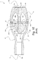
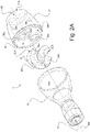
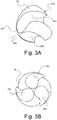
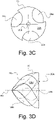
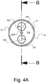
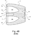
- Figures 1A-E to 4A-E are illustrative of a first, preferred embodiment of the invention. More specifically, there is shown a nozzle, generally identified by reference numeral 1, with a nozzle inlet 1A having a single inlet aperture (visible in Figures 1A , 1C-E and 2A-B ) and a nozzle outlet 1B having a pair of outlet apertures (visible in Figures 1B-C , 1E and 2A-B ).
- the inlet aperture acting as nozzle inlet 1A and the pair of outlet apertures acting as nozzle outlet 1B are advantageously aligned along, respectively distributed about a same axis, identified by reference sign RA.
- nozzle 1 exhibits an essentially elongated shape, with the nozzle inlet 1A and nozzle outlet 1B being provided at two longitudinal ends of the nozzle 1.
- the nozzle inlet 1A is coupled to an adequate fluid supply (not shown), such as a water supply, using e.g. a flexible tubing or the like.
- the nozzle 1 is configured so as to allow fluid to flow from the nozzle inlet 1A, through the nozzle 1 and exit at the nozzle outlet 1B, namely as a pulsatile jet of fluid projecting from the nozzle outlet 1B.
- the pulsatile jet of fluid is produced passively thanks to a number of elements located inside a shell 10 of the nozzle 1 that interact with the fluid flow, which elements are specifically designed to turn the incoming fluid flow entering the nozzle 1A into the pulsatile jet of fluid projecting from the nozzle outlet 1B.
- nozzle 1 comprises a rotor element 20 and a stationary splitter element 30 that are located one after the other inside the shell 10, along the passage of the fluid flow.
- Rotor element 20 is configured to be driven into rotation about a rotation axis RA upon being subjected to the action of the fluid flow entering the nozzle inlet 1A and circulating through the nozzle 1.
- the axis along or about which the single inlet aperture acting as nozzle inlet 1A and the pair of outlet apertures acting as nozzle outlet 1B are respectively aligned and distributed coincides with the axis of rotation RA of the rotor element 20.
- the rotor element 20 is positioned in front of and allowed to rotate inside the shell 10 with respect to the stationary splitter element 30.
- the shell 10 advantageously includes a front shell element 11 (comprising the aforementioned nozzle inlet 1A) and a rear shell element 12 (comprising the aforementioned nozzle outlet 1B) that are assembled together to form the shell 10.
- front shell element 11 includes an inner cavity 11A that is configured and dimensioned to receive the rotor element 20 and allow it to rotate under the action of the fluid flow.
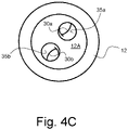
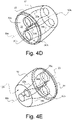
- Stationary splitter element 30 here advantageously forms an integral part of the rear shell element 12 (see also Figures 4A-E ) but may alternatively be designed as a separate element housed inside the rear shell element 12 and secured thereto to remain stationary.
- splitter element 30 and rear shell element 12 in effect form a combined, integral splitter and rear shell element.
- rotor element 20 comprises a plurality of (namely three) peripheral helical grooves 20a, 20b, 20c that are configured to permit passage of the fluid flow and cause rotation of the rotor element 20 about its rotation axis RA.
- peripheral helical grooves 20a, 20b, 20c are evenly distributed about the circumference of the rotor element, namely at 120° one from the other.
- Each peripheral helical groove 20a, 20b, 20c here exhibits a substantially hemi-circular groove profile but other groove profiles could be contemplated.
- the outer peripheral surface of the rotor element 20 is delineated by a generally ogival surface of revolution.
- the pointed end of the rotor element 20 is oriented towards the nozzle inlet 1A so that fluid flows around the rotor element 20 and through the peripheral helical grooves 20a, 20b, 20c, driving rotor element 20 into rotation in the process.
- the rear surface 20A of rotor element 20 is substantially flat and faces the front surface 30A of the stationary splitter element 30, which front surface 30A is likewise substantially flat.
- rotor element 20 is rotatably supported onto the splitter element 30.
- Such rotatable support may be realized in a variety of different ways.
- rotor element 20 and splitter element 30 both include a blind hole 20B, resp. 30B, configured and dimensioned to receive a shaft (not shown) providing rotatable support of the rotor element 20 onto the splitter element 30.
- Rotatable support may be ensured by a simple plain bearing (e.g. through direct interaction of the shaft with one or the other of the relevant blind holes 20B, 30B) or by any other adequate means, including e.g. ball bearings.
- splitter element 30 comprises a plurality of (namely two) splitter openings 30a, 30b communicating with a downstream end of the plurality of peripheral helical grooves 20a, 20b, 20c of the rotor element 20 to cause splitting and modulation of the fluid flow as a function of rotation of the rotor element 20 with respect to the stationary splitter element 30.
- splitter openings 30a, 30b are in effect circular openings formed in a front portion 31 of splitter element 30, in diametrically opposed positions.
- openings 30a, 30b are dimensioned and positioned to communicate with the relevant open portions on the rear surface 20A of the rotor element 20 that coincide with the downstream end of the peripheral helical grooves 20a, 20b, 20c, the rear surface 20A selectively acting as obturator for the splitter openings 30a, 30b depending on the rotational position of the rotor element 20.
- Fluid flow is in effect split between the splitter openings 30a, 30b as a function of the rotational position of the rotor element 20 with respect to the splitter element 30 and the amount of fluid allowed to flow through each splitter opening 30a, 30b is modulated as a function of such rotational position.
- splitting and modulation will depend in particular on the relevant numbers, positions and dimensions of the peripheral helical grooves on the rotor element 20 and of the splitter openings on the splitter element 30.
- the amount of fluid allowed to enter each splitter opening 30a, 30b is repeatedly modulated between a low value and a high value, with repeating modulation cycles each corresponding to a relative angular displacement of the rotor element 20 of 120° with respect to the splitter element 30 (corresponding to the relevant angle separating the peripheral helical grooves 20a, 20b, 20c). Furthermore, modulation of the amount of fluid allowed to enter the first splitter opening 30a is out of phase compared to modulation of the amount of fluid allowed to enter the second splitter opening 30b, owing to the fact that the angle separating the splitter openings 30a, 30b is of 180° in the present instance. In the illustrated example, the phase difference corresponds to a relative angular displacement of the rotor element 20 of 60° with respect to the splitter element 30. In other words, fluid is allowed to flow through the splitter openings 30a, 30b in an alternate manner.
- nozzle 1 further comprises flow conditioning elements located inside the shell 10, downstream of the splitter openings 30a, 30b. These flow conditioning elements are configured to cause recombination of the fluid flow, split and modulated by the splitter element 30, into a pulsatile jet of fluid projecting from the nozzle outlet 1B. More specifically, in the illustrated embodiment, the flow conditioning elements include a plurality of (namely two) outlet conduits 35a, 35b associated to the splitter openings 30a, 30b. That is, each splitter opening 30a, 30b opens into a corresponding one of the outlet conduits 35a, 35b, namely splitter opening 30a opens into outlet conduit 35a, while splitter opening 30b opens into outlet conduit 35b.
- outlet conduits 35a, 35b advantageously form an integral part of the splitter element 30 (and of the rear shell element 12), each outlet conduit 35a, 35b extending from the associated splitter opening 30a, resp. 30b, to the rear end of the nozzle 1. More specifically, outlet conduits 35a, 35b open in an outlet surface 12A (see Figures 1B , 1E , 2A and 4B-E ), which outlet surface is concavely shaped as shown. Outlet conduits 35a, 35b are here arranged to produce converging, modulated jets of fluid at the nozzle outlet 1B that recombine to form the pulsatile jet of fluid downstream of the nozzle outlet 1B.
- the outlet conduits 35a, 35b advantageously have a twisted configuration, which imparts a three-dimensional spiralling effect (or rotational spin) to the pulsatile jet of fluid.
- Tests carried by the Applicant using the nozzle 1 of Figures 1A-E to 4A-E have demonstrated superior ability to clean surfaces from residues, which first embodiment accordingly constitutes a particularly advantageous embodiment of the invention for applications making use of the pulsatile jet of fluid as a cleaning medium.
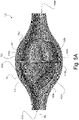
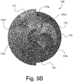
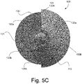
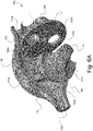
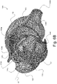
- Figures 5A-C and 6A-B are illustrative of a second embodiment of the invention. More specifically, there is shown a nozzle, generally identified by reference numeral 100, with a nozzle inlet 100A having a single inlet aperture (visible in Figures 5A-B and 6A ) and a nozzle outlet 100B likewise having a single outlet aperture (visible in Figures 5A , 5C and 6B ).
- the inlet aperture acting as nozzle inlet 100A and the outlet aperture acting as nozzle outlet 100B are likewise advantageously aligned along a same axis which coincides with the axis of rotation RA of the rotor element, designated by reference numeral 120.
- Nozzle 100 once again exhibits an essentially elongated shape, here with a central bulged portion, with the nozzle inlet 100A and nozzle outlet 100B being provided at two longitudinal ends of the nozzle 100.
- the nozzle inlet 100A is likewise coupled to an adequate fluid supply (not shown), nozzle 100 being configured so as to allow fluid to flow from the nozzle inlet 100A, through the nozzle 100 and exit at the nozzle outlet 100B as a pulsatile jet of fluid projecting from the nozzle outlet 100B.
- Nozzle 100 likewise includes a shell 110 (one half of which being omitted in the illustrations of Figures 5A-C and 6A-B for the sake illustration) housing the rotor element 120 and associated stationary splitter element, designated by reference numeral 130. More specifically, shell 110 includes a bulged inner cavity 110A that is here configured and dimensioned to receive not only the rotor element 120 but also the splitter element 130. The front portion of the splitter element 130 is here shaped as an essentially circular splitter plate 131 that is held and secured into a corresponding inner peripheral groove 110B formed inside the shell 110.
- splitter element 130 does not form an integral part of the shell 110 but is rather distinct from the shell 110 and secured therein to remain stationary.
- Rotor element 120 is basically similar to rotor element 20 described previously.
- the outer peripheral surface thereof is once again delineated by a generally ogival surface of revolution, with the pointed end of the rotor element 120 being oriented towards the nozzle inlet 100A so that fluid flows around the rotor element 120 and through a plurality of (namely three) peripheral helical grooves 120a, 120b, 120c, driving rotor element 120 into rotation in the process.
- the rear surface 120A of rotor element 120 faces the front surface 130A of the splitter element 130 in a manner similar to the first embodiment described above to likewise selectively act as obturator for the splitter openings provided on the splitter element 130, depending on the rotational position of the rotor element 120.
- Rotor element 120 is likewise advantageously supported onto the splitter element 130 by means of suitable bearing arrangement (not shown).
- splitter element 130 comprises a plurality of (namely two) splitter openings 130a, 130b (visible in Figures 5C and 6A-B ) communicating with a downstream end of the plurality of peripheral helical grooves 120a, 120b, 120c of the rotor element 120 to cause splitting and modulation of the fluid flow as a function of rotation of the rotor element 120 with respect to the stationary splitter element 130.
- Splitting and modulation of fluid flow occurs in the same manner as previously described in connection with the first embodiment.
- Nozzle 100 likewise further comprises flow conditioning elements located inside the shell 110, downstream of the splitter openings 130a, 130b, which flow conditioning elements are configured to cause recombination of the fluid flow, split and modulated by the splitter element 130, into a pulsatile jet of fluid projecting from the nozzle outlet 100B.
- the flow conditioning elements include a plurality of (namely two) turning vanes 135a, 135b associated to the splitter openings 130a, 130b.
- a corresponding one of the turning vanes 135a, 135b is provided downstream of each splitter opening 130a, 130b, namely turning vane 135a is provided downstream of splitter opening 130a, while turning vane 135b is provided downstream of splitter opening 130b.
- turning vanes 135a, 135b advantageously form an integral part of the splitter element 130.
- Turning vanes 135a, 135b are here arranged to cause recombination of the fluid flow, split and modulated by the splitter element 130, upstream of the nozzle outlet 100B to form the desired pulsatile jet of fluid. This is once again made possible thanks to the aforementioned splitting and modulation of the fluid flow by the splitter element 130, causing fluid to be fed alternately to the turning vanes 135a, 135b to produce two, out-of-phase, modulated jets of fluid that recombine, here upstream of the nozzle outlet 100B.
- a three-dimensional spiralling effect can likewise be imparted to the pulsatile jet of fluid projecting from the nozzle outlet 100B.
- the nozzle of the invention may be made of any suitable materials. With respect to nozzles that are intended to be used for sanitary or hygienic purposes, suitable plastic materials may especially come into consideration. Part or all of the nozzle components could however be formed in other materials, including but not limited to stainless steel or aluminium.
- the nozzle of the invention may be incorporated into any suitable device generally comprising a fluid supply coupled to the nozzle inlet of the nozzle of the invention.
- the nozzle inlet could in particular be coupled to the fluid supply via a valve (such as a mechanically or electrically actuated valve) configured to selective close or open the connection to the fluid supply depending on operational requirements.
- the rotor element may exhibit any adequate shape and configuration. While a generally ogival surface of revolution is preferred, the outer peripheral surface of the rotor element could for instance be delineated by a generally conical surface of revolution.
- the number of peripheral helical grooves may in that respect differ from three.
- the number of splitter openings provided on the splitter element may differ from two.
- the exterior shape of the nozzle of the invention may further differ in practice from the elongated shape shown in Figures 1A-E to 4A-E or the bulged shape shown in Figures 5A-C to 6A-B . In effect, any adequate exterior shape could be contemplated.
- one or multiple inlets could be contemplated as nozzle inlet in order to feed the nozzle with fluid and cause rotation of the rotor element.
- the stationary splitter element may indifferently form an integral part of the shell or be distinct from the shell and secured therein to remain stationary.
- flow conditioning elements described in connection with the first and second embodiments discussed previously preferably form an integral part of the splitter element, such flow conditioning elements could potentially be formed onto a distinct element secured inside the shell in a fixed relationship with respect to the splitter element.
Landscapes
- Health & Medical Sciences (AREA)
- Dentistry (AREA)
- Epidemiology (AREA)
- Life Sciences & Earth Sciences (AREA)
- Animal Behavior & Ethology (AREA)
- General Health & Medical Sciences (AREA)
- Public Health (AREA)
- Veterinary Medicine (AREA)
- Nozzles (AREA)
Priority Applications (7)
| Application Number | Priority Date | Filing Date | Title |
|---|---|---|---|
| EP21172887.8A EP4086007A1 (de) | 2021-05-07 | 2021-05-07 | Düse zur erzeugung von einem pulsierenden flüssigkeitsstrahl |
| CA3216994A CA3216994A1 (en) | 2021-05-07 | 2022-05-02 | Nozzle for the production of a pulsatile jet of fluid |
| US18/289,456 US20240253069A1 (en) | 2021-05-07 | 2022-05-02 | Nozzle for the production of a pulsatile jet of fluid |
| ES22726509T ES2977868T3 (es) | 2021-05-07 | 2022-05-02 | Boquilla para la producción de un chorro pulsátil de fluido |
| CN202280032413.0A CN117241893A (zh) | 2021-05-07 | 2022-05-02 | 用于产生流体的脉动射流的喷嘴 |
| PCT/IB2022/054038 WO2022234432A1 (en) | 2021-05-07 | 2022-05-02 | Nozzle for the production of a pulsatile jet of fluid |
| EP22726509.7A EP4164806B1 (de) | 2021-05-07 | 2022-05-02 | Düse zur erzeugung eines pulsatilen flüssigkeitsstrahls |
Applications Claiming Priority (1)
| Application Number | Priority Date | Filing Date | Title |
|---|---|---|---|
| EP21172887.8A EP4086007A1 (de) | 2021-05-07 | 2021-05-07 | Düse zur erzeugung von einem pulsierenden flüssigkeitsstrahl |
Publications (1)
| Publication Number | Publication Date |
|---|---|
| EP4086007A1 true EP4086007A1 (de) | 2022-11-09 |
Family
ID=75887824
Family Applications (2)
| Application Number | Title | Priority Date | Filing Date |
|---|---|---|---|
| EP21172887.8A Withdrawn EP4086007A1 (de) | 2021-05-07 | 2021-05-07 | Düse zur erzeugung von einem pulsierenden flüssigkeitsstrahl |
| EP22726509.7A Active EP4164806B1 (de) | 2021-05-07 | 2022-05-02 | Düse zur erzeugung eines pulsatilen flüssigkeitsstrahls |
Family Applications After (1)
| Application Number | Title | Priority Date | Filing Date |
|---|---|---|---|
| EP22726509.7A Active EP4164806B1 (de) | 2021-05-07 | 2022-05-02 | Düse zur erzeugung eines pulsatilen flüssigkeitsstrahls |
Country Status (6)
| Country | Link |
|---|---|
| US (1) | US20240253069A1 (de) |
| EP (2) | EP4086007A1 (de) |
| CN (1) | CN117241893A (de) |
| CA (1) | CA3216994A1 (de) |
| ES (1) | ES2977868T3 (de) |
| WO (1) | WO2022234432A1 (de) |
Cited By (1)
| Publication number | Priority date | Publication date | Assignee | Title |
|---|---|---|---|---|
| WO2025093399A1 (de) * | 2023-10-31 | 2025-05-08 | Udo Zehe | Reinigungsdüse, set, verwendung einer reinigungsdüse, verfahren zur herstellung eines rotationskörpers und verfahren zur nachrüstung einer druckluftleitung |
Citations (6)
| Publication number | Priority date | Publication date | Assignee | Title |
|---|---|---|---|---|
| US3004719A (en) * | 1957-09-26 | 1961-10-17 | Phillips Petroleum Co | Apparatus for spraying viscous liquids |
| US4098461A (en) * | 1976-07-09 | 1978-07-04 | Franz Scheffer Ohg | Pipe nipple for the discharge of a solid water jet |
| US5444879A (en) * | 1993-04-27 | 1995-08-29 | B&S Plastics, Inc. | Pulsating water injection system and valve for hydrotherapy spa with helical water distribution groove |
| US6003534A (en) * | 1996-02-12 | 1999-12-21 | The Minister Of Agriculture For The State Of New South Wales | Anhydrous ammonia distributor |
| US6375088B1 (en) * | 1999-08-11 | 2002-04-23 | International Business Machines Corp. | Fluid delivery device with pulsating linear discharge and fluid cleaning method |
| US6997400B1 (en) * | 2002-07-17 | 2006-02-14 | Iowa State University Research Foundation, Inc. | Apparatus and method for reducing anhydrous ammonia application by optimizing distribution |
Family Cites Families (9)
| Publication number | Priority date | Publication date | Assignee | Title |
|---|---|---|---|---|
| DE2755893C3 (de) * | 1977-12-15 | 1988-07-07 | Friedrich Grohe Armaturenfabrik Gmbh & Co, 5870 Hemer | Abdeckscheibe für Sprühdüsen oder dergleichen |
| US4508665A (en) * | 1983-06-20 | 1985-04-02 | Kdi American Products, Inc. | Retrofit pulsator apparatus and method for an air/water mixer of a swimming pool, therapy tub, spa or the like |
| US5920925A (en) * | 1998-04-01 | 1999-07-13 | B&S Plastics, Inc. | Pulsating hydrotherapy jet system |
| US6942164B2 (en) * | 2003-02-28 | 2005-09-13 | Rain Bird Corporation | Rotating stream sprinkler with turbine speed governor |
| CN102091678B (zh) * | 2010-12-21 | 2012-11-14 | 常州力马干燥工程有限公司 | 气流式雾化器 |
| US11511289B2 (en) * | 2017-07-13 | 2022-11-29 | Rain Bird Corporation | Rotary full circle nozzles and deflectors |
| US11185874B2 (en) * | 2018-07-11 | 2021-11-30 | Phoenix Closures, Inc. | Nozzle tips with neck portions for reduced cleaning times |
| KR102269686B1 (ko) * | 2019-01-14 | 2021-06-24 | 이준범 | 원주경사방향으로 회오리 치게 분사되는 세척노즐 |
| US11980900B2 (en) * | 2019-03-11 | 2024-05-14 | Kristy LaMariana | Adjustable nozzle |
-
2021
- 2021-05-07 EP EP21172887.8A patent/EP4086007A1/de not_active Withdrawn
-
2022
- 2022-05-02 US US18/289,456 patent/US20240253069A1/en active Pending
- 2022-05-02 CN CN202280032413.0A patent/CN117241893A/zh active Pending
- 2022-05-02 EP EP22726509.7A patent/EP4164806B1/de active Active
- 2022-05-02 ES ES22726509T patent/ES2977868T3/es active Active
- 2022-05-02 WO PCT/IB2022/054038 patent/WO2022234432A1/en not_active Ceased
- 2022-05-02 CA CA3216994A patent/CA3216994A1/en active Pending
Patent Citations (6)
| Publication number | Priority date | Publication date | Assignee | Title |
|---|---|---|---|---|
| US3004719A (en) * | 1957-09-26 | 1961-10-17 | Phillips Petroleum Co | Apparatus for spraying viscous liquids |
| US4098461A (en) * | 1976-07-09 | 1978-07-04 | Franz Scheffer Ohg | Pipe nipple for the discharge of a solid water jet |
| US5444879A (en) * | 1993-04-27 | 1995-08-29 | B&S Plastics, Inc. | Pulsating water injection system and valve for hydrotherapy spa with helical water distribution groove |
| US6003534A (en) * | 1996-02-12 | 1999-12-21 | The Minister Of Agriculture For The State Of New South Wales | Anhydrous ammonia distributor |
| US6375088B1 (en) * | 1999-08-11 | 2002-04-23 | International Business Machines Corp. | Fluid delivery device with pulsating linear discharge and fluid cleaning method |
| US6997400B1 (en) * | 2002-07-17 | 2006-02-14 | Iowa State University Research Foundation, Inc. | Apparatus and method for reducing anhydrous ammonia application by optimizing distribution |
Non-Patent Citations (1)
| Title |
|---|
| ENNO SABELBERG ET AL.: "Design, development, and validation of concepts for generating passive pulsation in cooling nozzles", CASE STUDIES IN THERMAL ENGINEERING, vol. 7, March 2016 (2016-03-01), pages 103 - 108, Retrieved from the Internet <URL:https:/Idoi.orq/10.1016/i.csite.2016.03.005> |
Cited By (1)
| Publication number | Priority date | Publication date | Assignee | Title |
|---|---|---|---|---|
| WO2025093399A1 (de) * | 2023-10-31 | 2025-05-08 | Udo Zehe | Reinigungsdüse, set, verwendung einer reinigungsdüse, verfahren zur herstellung eines rotationskörpers und verfahren zur nachrüstung einer druckluftleitung |
Also Published As
| Publication number | Publication date |
|---|---|
| CN117241893A (zh) | 2023-12-15 |
| EP4164806B1 (de) | 2024-02-28 |
| EP4164806C0 (de) | 2024-02-28 |
| US20240253069A1 (en) | 2024-08-01 |
| WO2022234432A1 (en) | 2022-11-10 |
| ES2977868T3 (es) | 2024-09-02 |
| EP4164806A1 (de) | 2023-04-19 |
| CA3216994A1 (en) | 2022-11-10 |
Similar Documents
| Publication | Publication Date | Title |
|---|---|---|
| US6254014B1 (en) | Fluid delivery apparatus | |
| US8794543B2 (en) | Low-speed pulsating showerhead | |
| US6360967B1 (en) | Shower head for a sanitary shower | |
| US10138907B2 (en) | Rotary energy recovery device | |
| US11213837B2 (en) | Kinetic water delivery devices | |
| AU690345B2 (en) | Gear-type rotary sprinkler | |
| WO2008083229A2 (en) | Low speed pulsating showerhead | |
| EP4164806B1 (de) | Düse zur erzeugung eines pulsatilen flüssigkeitsstrahls | |
| US4081135A (en) | Pulsating shower head | |
| US12090497B2 (en) | Showerhead with multiple pairs of nozzles that actuate sequentially in a loop | |
| US11583872B2 (en) | Showerhead engine for rotating spray | |
| US3753435A (en) | Multi-jet massager | |
| CN102861685A (zh) | 旋转喷嘴系统 | |
| US6988676B2 (en) | Turbine drive rotary spray cleaner | |
| JP2006158971A (ja) | 回転可能末端内視鏡ヘッドを備えた内視鏡 | |
| US8814061B1 (en) | Rotary nozzle cleaning apparatus with improved stem | |
| CN101516521A (zh) | 用于花洒和手持喷头的脉动喷水按摩组件 | |
| CN117960417A (zh) | 出水装置及淋浴设备 | |
| CN108714493B (zh) | 一种间歇出水的出水装置 | |
| ES2526914T3 (es) | Dispositivo de limpieza de recipientes | |
| CN105268568B (zh) | 一种可360度旋转的节能装置 | |
| KR20030024930A (ko) | 샤워기용 샤워 헤드 | |
| CN222829853U (zh) | 一种间歇出水机构、间歇出水装置和花洒 | |
| CN121016977A (zh) | 一种灯泡动态水结构以及出水装置 | |
| RU2271871C2 (ru) | Душевая головка для сантехнического душа |
Legal Events
| Date | Code | Title | Description |
|---|---|---|---|
| PUAI | Public reference made under article 153(3) epc to a published international application that has entered the european phase |
Free format text: ORIGINAL CODE: 0009012 |
|
| STAA | Information on the status of an ep patent application or granted ep patent |
Free format text: STATUS: THE APPLICATION HAS BEEN PUBLISHED |
|
| AK | Designated contracting states |
Kind code of ref document: A1 Designated state(s): AL AT BE BG CH CY CZ DE DK EE ES FI FR GB GR HR HU IE IS IT LI LT LU LV MC MK MT NL NO PL PT RO RS SE SI SK SM TR |
|
| STAA | Information on the status of an ep patent application or granted ep patent |
Free format text: STATUS: THE APPLICATION IS DEEMED TO BE WITHDRAWN |
|
| 18D | Application deemed to be withdrawn |
Effective date: 20230510 |