EP4085745B1 - Verbesserte navigation für ein robotisches arbeitswerkzeug - Google Patents
Verbesserte navigation für ein robotisches arbeitswerkzeug Download PDFInfo
- Publication number
- EP4085745B1 EP4085745B1 EP22166422.0A EP22166422A EP4085745B1 EP 4085745 B1 EP4085745 B1 EP 4085745B1 EP 22166422 A EP22166422 A EP 22166422A EP 4085745 B1 EP4085745 B1 EP 4085745B1
- Authority
- EP
- European Patent Office
- Prior art keywords
- work tool
- robotic
- robotic work
- boundary
- work area
- Prior art date
- Legal status (The legal status is an assumption and is not a legal conclusion. Google has not performed a legal analysis and makes no representation as to the accuracy of the status listed.)
- Active
Links
Images


Classifications
-
- G—PHYSICS
- G05—CONTROLLING; REGULATING
- G05D—SYSTEMS FOR CONTROLLING OR REGULATING NON-ELECTRIC VARIABLES
- G05D1/00—Control of position, course, altitude or attitude of land, water, air or space vehicles, e.g. using automatic pilots
- G05D1/02—Control of position or course in two dimensions
- G05D1/021—Control of position or course in two dimensions specially adapted to land vehicles
- G05D1/0259—Control of position or course in two dimensions specially adapted to land vehicles using magnetic or electromagnetic means
-
- A—HUMAN NECESSITIES
- A01—AGRICULTURE; FORESTRY; ANIMAL HUSBANDRY; HUNTING; TRAPPING; FISHING
- A01D—HARVESTING; MOWING
- A01D34/00—Mowers; Mowing apparatus of harvesters
- A01D34/006—Control or measuring arrangements
- A01D34/008—Control or measuring arrangements for automated or remotely controlled operation
-
- G—PHYSICS
- G05—CONTROLLING; REGULATING
- G05D—SYSTEMS FOR CONTROLLING OR REGULATING NON-ELECTRIC VARIABLES
- G05D1/00—Control of position, course, altitude or attitude of land, water, air or space vehicles, e.g. using automatic pilots
- G05D1/02—Control of position or course in two dimensions
- G05D1/021—Control of position or course in two dimensions specially adapted to land vehicles
- G05D1/0259—Control of position or course in two dimensions specially adapted to land vehicles using magnetic or electromagnetic means
- G05D1/0265—Control of position or course in two dimensions specially adapted to land vehicles using magnetic or electromagnetic means using buried wires
-
- G—PHYSICS
- G05—CONTROLLING; REGULATING
- G05D—SYSTEMS FOR CONTROLLING OR REGULATING NON-ELECTRIC VARIABLES
- G05D1/00—Control of position, course, altitude or attitude of land, water, air or space vehicles, e.g. using automatic pilots
- G05D1/02—Control of position or course in two dimensions
- G05D1/021—Control of position or course in two dimensions specially adapted to land vehicles
- G05D1/0276—Control of position or course in two dimensions specially adapted to land vehicles using signals provided by a source external to the vehicle
- G05D1/0278—Control of position or course in two dimensions specially adapted to land vehicles using signals provided by a source external to the vehicle using satellite positioning signals, e.g. GPS
-
- G—PHYSICS
- G05—CONTROLLING; REGULATING
- G05D—SYSTEMS FOR CONTROLLING OR REGULATING NON-ELECTRIC VARIABLES
- G05D1/00—Control of position, course, altitude or attitude of land, water, air or space vehicles, e.g. using automatic pilots
- G05D1/02—Control of position or course in two dimensions
- G05D1/021—Control of position or course in two dimensions specially adapted to land vehicles
- G05D1/0276—Control of position or course in two dimensions specially adapted to land vehicles using signals provided by a source external to the vehicle
- G05D1/028—Control of position or course in two dimensions specially adapted to land vehicles using signals provided by a source external to the vehicle using a RF signal
-
- G—PHYSICS
- G05—CONTROLLING; REGULATING
- G05D—SYSTEMS FOR CONTROLLING OR REGULATING NON-ELECTRIC VARIABLES
- G05D1/00—Control of position, course, altitude or attitude of land, water, air or space vehicles, e.g. using automatic pilots
- G05D1/20—Control system inputs
- G05D1/24—Arrangements for determining position or orientation
- G05D1/242—Means based on the reflection of waves generated by the vehicle
-
- G—PHYSICS
- G05—CONTROLLING; REGULATING
- G05D—SYSTEMS FOR CONTROLLING OR REGULATING NON-ELECTRIC VARIABLES
- G05D1/00—Control of position, course, altitude or attitude of land, water, air or space vehicles, e.g. using automatic pilots
- G05D1/20—Control system inputs
- G05D1/24—Arrangements for determining position or orientation
- G05D1/247—Arrangements for determining position or orientation using signals provided by artificial sources external to the vehicle, e.g. navigation beacons
-
- G—PHYSICS
- G05—CONTROLLING; REGULATING
- G05D—SYSTEMS FOR CONTROLLING OR REGULATING NON-ELECTRIC VARIABLES
- G05D1/00—Control of position, course, altitude or attitude of land, water, air or space vehicles, e.g. using automatic pilots
- G05D1/60—Intended control result
- G05D1/648—Performing a task within a working area or space, e.g. cleaning
-
- G—PHYSICS
- G05—CONTROLLING; REGULATING
- G05D—SYSTEMS FOR CONTROLLING OR REGULATING NON-ELECTRIC VARIABLES
- G05D1/00—Control of position, course, altitude or attitude of land, water, air or space vehicles, e.g. using automatic pilots
- G05D1/02—Control of position or course in two dimensions
- G05D1/021—Control of position or course in two dimensions specially adapted to land vehicles
- G05D1/0212—Control of position or course in two dimensions specially adapted to land vehicles with means for defining a desired trajectory
- G05D1/0219—Control of position or course in two dimensions specially adapted to land vehicles with means for defining a desired trajectory ensuring the processing of the whole working surface
-
- G—PHYSICS
- G05—CONTROLLING; REGULATING
- G05D—SYSTEMS FOR CONTROLLING OR REGULATING NON-ELECTRIC VARIABLES
- G05D1/00—Control of position, course, altitude or attitude of land, water, air or space vehicles, e.g. using automatic pilots
- G05D1/40—Control within particular dimensions
- G05D1/43—Control of position or course in two dimensions [2D]
-
- G—PHYSICS
- G05—CONTROLLING; REGULATING
- G05D—SYSTEMS FOR CONTROLLING OR REGULATING NON-ELECTRIC VARIABLES
- G05D2105/00—Specific applications of the controlled vehicles
- G05D2105/15—Specific applications of the controlled vehicles for harvesting, sowing or mowing in agriculture or forestry
-
- G—PHYSICS
- G05—CONTROLLING; REGULATING
- G05D—SYSTEMS FOR CONTROLLING OR REGULATING NON-ELECTRIC VARIABLES
- G05D2107/00—Specific environments of the controlled vehicles
- G05D2107/10—Outdoor regulated spaces
-
- G—PHYSICS
- G05—CONTROLLING; REGULATING
- G05D—SYSTEMS FOR CONTROLLING OR REGULATING NON-ELECTRIC VARIABLES
- G05D2107/00—Specific environments of the controlled vehicles
- G05D2107/20—Land use
- G05D2107/23—Gardens or lawns
-
- G—PHYSICS
- G05—CONTROLLING; REGULATING
- G05D—SYSTEMS FOR CONTROLLING OR REGULATING NON-ELECTRIC VARIABLES
- G05D2109/00—Types of controlled vehicles
- G05D2109/10—Land vehicles
-
- G—PHYSICS
- G05—CONTROLLING; REGULATING
- G05D—SYSTEMS FOR CONTROLLING OR REGULATING NON-ELECTRIC VARIABLES
- G05D2111/00—Details of signals used for control of position, course, altitude or attitude of land, water, air or space vehicles
- G05D2111/30—Radio signals
Definitions
- This application relates to robotic work tools and in particular to a system and a method for providing an improved servicing, such as exiting a service station for a robotic work tool, such as a lawnmower.
- Automated or robotic power tools such as robotic lawnmowers are becoming increasingly more popular.
- a work area such as a garden
- the work area is enclosed by a boundary with the purpose of keeping the robotic lawnmower inside the work area.
- many robotic work tools are arranged to operate and navigate using a satellite navigations system, such as GNSS or GPS.
- the robotic work tool may also or alternatively be arranged to operate or navigate utilizing a beacon-based navigation system, such as UWB, or through combined systems such as RTK.
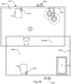
- Figure 1A shows a schematic view of an example of a typical work area 105, being a garden, in which a robotic work tool 10, such as a robotic lawnmower, is set to operate.
- the garden contains a number of obstacles, exemplified herein by a number (2) of trees (T), a stone (S) and a house structure (H).
- the trees are marked both with respect to their trunks (filled lines) and the extension of their foliage (dashed lines).
- the garden is enclosed by a boundary wire 120 through which a control signal 125 is transmitted by a signal generator 115 housed in a charging station 110, the control signal 125 generating a magnetic field that can be sensed by the robotic work tool 10.
- the garden may also comprise or be in the line of sight of at least one signal navigation device such as a beacon(s) or a satellite(s) (not explicitly shown in figure 1A , but shown and referenced 330 in figure 3A ).
- a virtual boundary 120' is indicated in figure 1A by the dotted line. From hereon there will be made no difference between the boundary being defined by the boundary wire 120 or as a virtual boundary 120' and the boundary of the work area 105 will hereafter simply be referred to as the boundary 120, unless otherwise specifically mentioned.
- FIG. 1A there is a further or second work area 105B - as opposed to the first work area 105A.
- This work area is also bounded by boundary 120B.
- the second boundary 120B may be provided through a boundary wire, or through a beacon or satellites.
- beacons have a limited range
- boundary-based systems also have a limited size
- This also allows for one and the same (set of) robotic work tool(s) to operate in two different work areas.
- the robotic work tool will prevent itself from crossing the boundary as is indicated in figure 1A , by the robotic work tool 10 stopping by the boundary 120A.
- Figure 1B shows a similar situation, but for overlapping work areas, where the overlap is referenced 105A/B.
- a robotic work tool 10 may even get stuck in the overlapping area 105A/B as it has to cross a boundary wire to get out of it, which it will prevent itself from doing.
- WO2020256619A1 discloses a robotic working tool system comprising a signal generator a robotic work tool, the signal generator including a signal pick-up and a controller, the controller being configured to receive information from the signal pick- up sensor, the information indicating an environment; determine a control signal to be used based on the information indicating the environment; cause the selected control signal to be generated and transmitted to the robotic work tool for controlling the operation of the robotic work tool.
- controller is further configured to travel along a transport path to the crossing zone.
- the crossing zone is located in the second work area.
- controller is further configured to travel along a transport path from the crossing zone into the second work area.
- controller is further configured to travel along the transport path from the crossing zone to a second crossing zone in the second work area.
- controller is further configured to operate in a transport mode while travelling along the transport path.
- the controller is further configured to determine that the robotic work tool is in the crossing zone based on a position of the robotic work tool and a known location of the crossing zone.
- controller is further configured to determine that the robotic work tool is in the crossing zone based on a sensing of the first boundary and/or the second boundary.
- the crossing zone is in range of the beacon.
- first crossing zone in the first work area there is a first crossing zone in the first work area and a second crossing zone in the second work area, wherein the first crossing zone in the first work area is connected to the second crossing zone in the second work area by a transport path.
- the robotic work tool further comprises a satellite signal navigation sensor and wherein the controller is configured to travel along the transport path connecting the first crossing zone in the first work area and the second crossing zone in the second work area navigating based on satellite navigation.
- the robotic work tool is configured to ignore the second boundary when operating in the first domain mode.
- the robotic work tool is configured to ignore the first boundary when operating in the second domain mode.
- the robotic work tool is configured for operating in a work area comprising an uneven surface, where objects are of a similar appearance to the surface and/or overhanging obstacles.
- the robotic work tool is a robotic lawnmower.
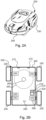
- Figure 2A shows a perspective view of a robotic work tool 200, here exemplified by a robotic lawnmower 200, having a body 240 and a plurality of wheels 230 (only one side is shown).
- the robotic work tool 200 may be a multi-chassis type or a mono-chassis type (as in figure 2A ).
- a multi-chassis type comprises more than one main body parts that are movable with respect to one another.
- a mono-chassis type comprises only one main body part.
- the robotic work tool is a self-propelled robotic work tool, capable of autonomous navigation within a work area, where the robotic work tool propels itself across or around the work area in a pattern (random or predetermined).
- FIG. 2B shows a schematic overview of the robotic work tool 200, also exemplified here by a robotic lawnmower 200.
- the robotic lawnmower 200 is of a mono-chassis type, having a main body part 240.
- the main body part 240 substantially houses all components of the robotic lawnmower 200.
- the robotic lawnmower 200 has a plurality of wheels 230.
- the robotic lawnmower 200 has four wheels 230, two front wheels and two rear wheels. At least some of the wheels 230 are drivably connected to at least one electric motor 250. It should be noted that even if the description herein is focused on electric motors, combustion engines may alternatively be used, possibly in combination with an electric motor.
- each of the wheels 230 is connected to a common or to a respective electric motor 255 for driving the wheels 230 to navigate the robotic lawnmower 200 in different manners.
- the wheels, the motor 255 and possibly the battery 250 are thus examples of components making up a propulsion device.
- the propulsion device may be controlled to propel the robotic lawnmower 200 in a desired manner, and the propulsion device will therefore be seen as synonymous with the motor(s) 250.
- the robotic lawnmower 200 also comprises a controller 210 and a computer readable storage medium or memory 220.
- the controller 210 may be implemented using instructions that enable hardware functionality, for example, by using executable computer program instructions in a general-purpose or special-purpose processor that may be stored on the memory 220 to be executed by such a processor.
- the controller 210 is configured to read instructions from the memory 220 and execute these instructions to control the operation of the robotic lawnmower 200 including, but not being limited to, the propulsion and navigation of the robotic lawnmower.
- the controller 210 in combination with the electric motor 255 and the wheels 230 forms the base of a navigation system (possibly comprising further components) for the robotic lawnmower, enabling it to be self-propelled as discussed under figure 2A ,
- the controller 210 may be implemented using any suitable, available processor or Programmable Logic Circuit (PLC).
- the memory 220 may be implemented using any commonly known technology for computer-readable memories such as ROM, RAM, SRAM, DRAM, FLASH, DDR, SDRAM or some other memory technology.
- the robotic lawnmower 200 may further be arranged with a wireless communication interface 215 for communicating with other devices, such as a server, a personal computer or smartphone, the charging station, and/or other robotic work tools. Examples of such wireless communication devices are Bluetooth ® , WiFi ® (IEEE802.1 1b), Global System Mobile (GSM) and LTE (Long Term Evolution), to name a few.
- the robotic lawnmower 200 also comprises a grass cutting device 260, such as a rotating blade 260 driven by a cutter motor 265.
- the grass cutting device being an example of a work tool 260 for a robotic work tool 200.
- the cutter motor 265 is accompanied or supplemented by various other components, such as a drive shaft to enable the driving of the grass cutting device, taken to be understood as included in the cutter motor 265.
- the cutter motor 265 will therefore be seen as representing a cutting assembly 265 or in the case of another work tool, a work tool assembly 265.
- the robotic lawnmower 200 further comprises at least one (signal) navigation sensor, such as an optical navigation sensor, an ultrasound sensor, a beacon navigation sensor and/or a satellite navigation sensor 290.
- the optical navigation sensor may be a camera-based sensor and/or a laser-based sensor.
- the beacon navigation sensor may be a Radio Frequency receiver, such as an Ultra Wide Band (UWB) receiver or sensor, configured to receive signals from a Radio Frequency beacon, such as a UWB beacon.
- the beacon navigation sensor may be an optical receiver configured to receive signals from an optical beacon.
- the satellite navigation sensor may be a GPS (Global Positioning System) device or other Global Navigation Satellite System (GNSS) device.
- GPS Global Positioning System
- GNSS Global Navigation Satellite System
- the magnetic sensors 270 as will be discussed below are optional.
- the work area may be specified as a virtual work area in a map application stored in the memory 220 of the robotic lawnmower 200.
- the virtual work area may be defined by a virtual boundary.
- the navigation sensor is a satellite navigation sensor, such as GPS, GNSS or a supplemental satellite navigation sensor such as RTK.
- the robotic lawnmower 200 also comprises deduced reckoning sensors 280.
- the deduced reckoning sensors may be odometers, accelerometer or other deduced reckoning sensors.
- the deduced reckoning sensors are comprised in the propulsion device, wherein a deduced reckoning navigation may be provided by knowing the current supplied to a motor and the time the current is supplied, which will give an indication of the speed and thereby distance for the corresponding wheel.
- the robotic lawnmower 200 is, in some embodiments, further configured to have at least one magnetic field sensor 270 arranged to detect the magnetic field and for detecting the boundary wire and/or for receiving (and possibly also sending) information to/from a signal generator (will be discussed with reference to figure 1 ).
- the sensors 270 may be connected to the controller 210, possibly via filters and an amplifier, and the controller 210 may be configured to process and evaluate any signals received from the sensors 270.
- the sensor signals are caused by the magnetic field being generated by the control signal being transmitted through the boundary wire. This enables the controller 210 to determine whether the robotic lawnmower 200 is close to or crossing the boundary wire, or inside or outside an area enclosed by the boundary wire.
- the robotic lawnmower 200 is arranged to operate according to a map of the work area 105, 305 (and possibly the surroundings of the work area 105) (referenced 305 in figure 3A and onwards) stored in the memory 220 of the robotic lawnmower 200.
- the map may be generated or supplemented as the robotic lawnmower 200 operates or otherwise moves around in the work area 105, 305.
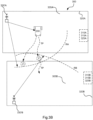
- Figure 3A shows a robotic work tool system 300 in some embodiments.
- the schematic view is not to scale.
- the robotic work tool system 300 of figure 3A corresponds in many aspects to the robotic work tool system 100 of figure 1A , except that the robotic work tool system 300 of figure 3A comprises a robotic work tool 200 according to the teachings herein.
- the work area shown in figure 3A is simplified for illustrative purposes but may contain some or all of the features of the work area of figure 1A , and even other and/or further features as will be hinted at below.
- the robotic work tool is exemplified by a robotic lawnmower, whereby the robotic work tool system may be a robotic lawnmower system or a system comprising a combinations of robotic work tools, one being a robotic lawnmower, but the teachings herein may also be applied to other robotic work tools adapted to operate within a work area.
- the robotic work tool system may be a robotic lawnmower system or a system comprising a combinations of robotic work tools, one being a robotic lawnmower, but the teachings herein may also be applied to other robotic work tools adapted to operate within a work area.
- the robotic work tool system 300 comprises a first work area 305A and a second work area 305B.
- the work areas have a charging station 310 which in some embodiments is arranged with a signal generator (not shown explicitly but seen as part of the charging station and referenced 315) for providing a control signal (not shown explicitly but seen as part of the charging station and referenced 325) through a boundary wire 320.
- the robotic work tool system 300 may comprise or be arranged to utilize at least one signal navigation device 330.
- a first being at least one satellite 330 (only one shown, but it should be clear that a minimum of three are needed for an accurate three 2 dimensional location).
- the second option being at least one beacon, such as an RTK base station (or beacon) or a UWB beacon 330'A, 330'B (only one shown for each work area).
- the work area 305 is in this application exemplified as a garden, but can also be other work areas as would be understood.
- the garden may contain a number of obstacles, for example a number of trees, stones, slopes and houses or other structures.
- the robotic work tool is arranged or configured to traverse and operate in a work area that is not essentially flat, but contains terrain that is of varying altitude, such as undulating, comprising hills or slopes or such.
- the ground of such terrain is not flat and it is not straightforward how to determine an angle between a sensor mounted on the robotic work tool and the ground.
- the robotic work tool is also or alternatively arranged or configured to traverse and operate in a work area that contains obstacles that are not easily discerned from the ground. Examples of such are grass or moss covered rocks, roots or other obstacles that are close to ground and of a similar colour or texture as the ground.
- the robotic work tool is also or alternatively arranged or configured to traverse and operate in a work area that contains obstacles that are overhanging, i.e. obstacles that may not be detectable from the ground up, such as low hanging branches of trees or bushes. Such a garden is thus not simply a flat lawn to be mowed or similar, but a work area of unpredictable structure and characteristics.
- the work area 305 exemplified with referenced to figure 3 may thus be such a non-uniform work area as disclosed in this paragraph that the robotic work tool is arranged to traverse and/or operate in.
- the robotic work tool 200 or rather the controller 210 of the robotic work tool 200 is configured to operate in two (or more) domain modes, where each domain mode is associated with a work area. As shown in figure 3A , the controller 210 is thus configured to operate in a first domain mode associated with the first work area 305A, in which first domain mode, the controller is configured to operate according to the first boundary 320A, and in a second domain mode associated with the second work area 305B, in which second domain mode, the controller is configured to operate according to the second boundary 320B. In some embodiments, the robotic work tool 200 is configured to ignore the second boundary 320B when operating in the first domain mode. In some embodiments, the robotic work tool 200 is configured to ignore the first boundary 320A when operating in the second domain mode.
- the first boundary 320A is in some embodiments associated with a first control signal 325A, that the controller is thus configured to sense with magnetic sensors 270 and operate according to when in the first domain mode.
- the first boundary 320A is in some embodiments associated with a first beacon 330'A, that the controller is thus configured to sense with navigation sensor 290 and operate according to when in the first domain mode.
- the second boundary 320B is in some embodiments associated with a second control signal 325B, that the controller is thus configured to sense with magnetic sensors 270 and operate according to when in the second domain mode.
- the second boundary 320B is in some embodiments associated with a second beacon 330'B, that the controller is thus configured to sense with navigation sensor 290 and operate according to when in the second domain mode.
- the robotic work tool is configured to determine that it is in a crossing zone referenced Z in figure 3A , and as the robotic work tool determines that the robotic work tool is in the crossing zone, the robotic work tool switches from one domain mode to another.
- the robotic work tool 200 when the robotic work tool 200 is thus in the crossing zone Z, it may switch from the first domain mode to the second domain mode.
- the first domain mode allowed the robotic work tool to navigate to the crossing zone inside the first work area 305A operating according to the first boundary 305A
- the second domain mode enables the robotic work tool to leave the first work area 305A and continue operating in the second work area 305B according to the second boundary 320B.
- the crossing zone Z thus indicates a point or area where it is safe to switch from operating according to one boundary to operating according to another boundary.
- the robotic work tool is configured to store a location of the crossing zone in the memory 220, and to navigate towards the crossing zone, using any known and available navigation technique. In some such embodiments the robotic work tool is thus configured to determine that it is in the crossing zone, based on determining the location of the robotic work tool and comparing it to the location of the crossing zone.
- the robotic work tool is configured to navigate towards the crossing zone along a transport path TP.
- the transport path may be a pre-specified path, or it may be a path that has been travelled previously. IN any case, the transport path is assumed to be safe for the robotic work tool to travel along as regards to avoiding obstacles and/or having a good reception of some boundary or other navigation means so as to avoid escaping or getting lost.
- the robotic work tool is configured to determine that the robotic work tool is in the crossing zone by comparing the reception of the two (or more) boundaries 320A, 320B. If both boundaries are reliably received, as in that they are received at a signal level and/or quality where they can be determined correctly, the robotic work tool determines that it is in a (safe) crossing zone. For overlapping work areas, the whole overlap may thus be a crossing zone Z.
- Figure 3A shows an example where the boundaries 320A, 320B are based on boundary wires.
- Figure 3B shows a similar example, but where the boundaries are based on other navigation techniques, such as based on signals from beacons 330'A, 330'B.
- a beacon may be a UWB beacon (or other beacon) or a base station for use with a RTK system.
- the range of the first work areas beacon 330'A is indicated RA and the range of the second work areas beacon 330'B is indicated RB.
- a crossing zone Z (or several) may be arranged in area(s) where signals are reliable received from both the first beacon(s) 330'A and the second beacon(s) 330'B, i.e. within range of both the first beacon(s) 330'A and the second beacon(s) 330'B.
- the crossing zone Z is inside a work area, where no specified further transportation path is needed.
- the crossing zone Z maybe outside a work area, where a specified further transportation path may be needed for guiding the robotic work tool 200 inside the work area being crossed over in to.
- the transport path guiding a robotic work tool 200 into a work area may in some embodiments simply be that the robotic work tool is aware of the boundary of the work are and navigates into it using any available navigation technique.
- the transport path guiding a robotic work tool 200 into a work area may in some embodiments, be a path that is (as discussed above) known to be reliable.
- Figure 3C shows an example similar to the examples of figures 3A and 3B , but in the example of figure 3C , the first boundary 320A is based on beacons 330'A sensed by the navigation sensor 290 and the second boundary 320B is based on a boundary wire sensed by the sensors 270.
- This example serves to show that a combination of boundaries is possible, and the domain mode may thus also include indications of which sensors to use for detecting a boundary.
- FIG 3D shows a further example where two work areas 305A and 305B are not adjacent one another.
- each work area 305A, 305B has a crossing zone Z', Z" which are connected by a transport path TP.
- the robotic work tool 200 is configured to propel itself to the first crossing zone Z' (i.e. the crossing zone of the first work area 305A).
- the robotic work tool travels along the travel path to the second crossing zone Z"(i.e. the crossing zone of the second work area 305B).
- the robotic work tool 200 is configured to determine that the robotic work tool 200 is in a crossing zone based on comparing the current position of the robotic work tool 200 with a known location for the crossing zone Z.
- the robotic work tool 200 is configured to determine that the robotic work tool 200 is in a crossing zone based on sensing surrounding signals such as the boundary 320A, 320B.
- the robotic work tool 200 is configured to switch from the first domain mode as it determines that the robotic work tool is in the first crossing zone.
- the robotic work tool 200 is configured to switch to the second operating mode and may navigate along the transport path using any available navigation technique.
- the second domain mode will allow the robotic work tool to enter the second work area, while not stop the robotic work tool 100 from leaving the first work area.
- the robotic work tool 200 is configured to switch to a transport mode, where the robotic work tool is configured to navigate regardless of the boundaries 320A, 320B. This allows the robotic work tool to both exit and enter any work area. In such embodiments the robotic work tool 200 is configured to switch to the second domain mode as the second crossing zone is reached.
- the robotic work tool travels along the robotic work tool based on the navigation sensor 290, receiving signals from the satellite 330 and/or form any of the beacons 330'A, 330'B.
- the robotic work tool is configured to deactivate the work tool 160 when travelling along a transport path.
- Figure 4 shows a flowchart for a general method according to herein.
- the method is for use in a robotic work tool as disclosed herein.
- the method comprises the robotic work tool 200 being in a first work area 305A and operating 400 in a first domain mode according to a first boundary 320A.
- the robotic work tool 200 determines 430 that the robotic work tool is in a crossing zone Z and in response thereto switches 440 domain mode and operates 470 in a second domain mode according to a second boundary 320B in a second work area 305B.
- the robotic work tool 200 is configured to determine 410 that it is to cross from the first work area 305A to the second work area 305B and in response thereto travel 420 to the crossing zone Z, possibly along a transport path.
- the robotic work tool 200 is configured to travel 450 from the crossing zone Z, possibly along a transport path, to the second work area 305B. In some embodiments, the robotic work tool 200 travels 460 along the transport path to a second crossing zone in the second work area 305B.
- the transport path is realized through a guide wire that emits a magnetic field (when in use) that may be sensed by the robotic work tool 200.
- the transport path is realized through a (series of) coordinates that the robotic work tool 200 may travel along using any available navigation technique capable of travelling along coordinates, for example using deduced reckoning, beacon navigation or satellite navigation.
Landscapes
- Engineering & Computer Science (AREA)
- Physics & Mathematics (AREA)
- Radar, Positioning & Navigation (AREA)
- Remote Sensing (AREA)
- Aviation & Aerospace Engineering (AREA)
- General Physics & Mathematics (AREA)
- Automation & Control Theory (AREA)
- Electromagnetism (AREA)
- Life Sciences & Earth Sciences (AREA)
- Environmental Sciences (AREA)
- Control Of Position, Course, Altitude, Or Attitude Of Moving Bodies (AREA)
- Manipulator (AREA)
Claims (15)
- Roboterarbeitswerkzeugsystem (300), umfassend einen ersten Arbeitsbereich (305A), der durch eine erste Begrenzung (320A) begrenzt ist, einen zweiten Arbeitsbereich (305B), der durch eine zweite Begrenzung (320B) begrenzt ist, und ein Roboterarbeitswerkzeug (200), umfassend eine Steuerung, wobeidas Roboterarbeitswerkzeugsystem (300) ferner einen Begrenzungsdraht (320), der eine oder beide der ersten und der zweiten Begrenzung markiert, umfasst und das Roboterarbeitswerkzeug (200) ferner einen Magnetsensor (270) umfasst, und/oderdas Roboterarbeitswerkzeugsystem (300) ferner eine Bake (330), die eine oder beide der ersten und der zweiten Begrenzung markiert, umfasst und das Roboterarbeitswerkzeug (200) ferner einen Navigationssensor (290) umfasst;wobei die Steuerung konfiguriert ist zum:dadurch gekennzeichnet ist, dass die Steuerung ferner konfiguriert, um zu ermöglichen, dass das Roboterarbeitswerkzeug (200) zu einer Kreuzungszone (Z) innerhalb des ersten Arbeitsbereichs (305A) navigiert, wobei sie gemäß der ersten Begrenzung (320A) in dem ersten Domänenmodus in Betrieb ist, zu bestimmen, dass sich das Roboterarbeitswerkzeug (200) in der Kreuzungszone (Z) befindet, und dann von dem ersten Domänenmodus in den zweiten Domänenmodus zu wechseln und um den ersten Arbeitsbereich (305A) zu verlassen, wobei sie basierend auf dem zweiten Domänenmodus in Betrieb ist, und weiterhin gemäß der zweiten Begrenzung (320B) in dem zweiten Arbeitsbereich (305B) in Betrieb zu sein.Inbetriebsein in einem ersten Domänenmodus in dem ersten Arbeitsbereich (305A) gemäß der ersten Begrenzung (320A) undInbetriebsein in einem zweiten Domänenmodus in dem zweiten Arbeitsbereich (305B) gemäß der zweiten Begrenzung (320B),wobei die Steuerung ferner konfiguriert ist, um in einem Domänenmodus für einen oder beide des ersten oder des zweiten Arbeitsbereichs in Betrieb zu sein, gemäß eines Erfassens eines Magnetfelds, das von dem Begrenzungskabel (320) ausgesendet wird, durch den Magnetsensor und/oder gemäß des Erfassens eines Signals, das von der Bake (330) ausgesendet wird, durch den Navigationssensor, und wobei das Roboterarbeitswerkzeugsystem (300)
- Roboterarbeitswerkzeugsystem (300) nach Anspruch 1, wobei die Steuerung ferner konfiguriert ist, um das Roboterarbeitswerkzeug (200) zu veranlassen, sich entlang eines Transportpfads (TP) zu der Kreuzungszone (Z) zu bewegen.
- Roboterarbeitswerkzeugsystem (300) nach Anspruch 1 oder 2, wobei die Steuerung ferner konfiguriert ist, um das Roboterarbeitswerkzeug (200) zu veranlassen, sich entlang eines Transportpfads (TP) von der Kreuzungszone (Z) in den zweiten Arbeitsbereich (305B) hinein zu bewegen.
- Roboterarbeitswerkzeugsystem (300) nach Anspruch 3, wobei die Steuerung ferner konfiguriert ist, um das Roboterarbeitswerkzeug (200) zu veranlassen, sich entlang des Transportpfads (TP) von der Kreuzungszone (Z') zu einer zweiten Kreuzungszone (Z") in dem zweiten Arbeitsbereich (305B) zu bewegen.
- Roboterarbeitswerkzeugsystem (300) nach einem der Ansprüche 2 bis 4, wobei die Steuerung ferner konfiguriert ist, um während eines Bewegens entlang des Transportpfads (TP) in einem Transportmodus in Betrieb zu sein.
- Roboterarbeitswerkzeugsystem (300) nach einem der vorstehenden Ansprüche, wobei die Steuerung ferner konfiguriert ist, um basierend auf einer Position des Roboterarbeitswerkzeugs (200) und einer bekannten Stelle der Kreuzungszone (Z) zu bestimmen, dass sich das Roboterarbeitswerkzeug (200) in der Kreuzungszone befindet.
- Roboterarbeitswerkzeugsystem (300) nach einem der vorstehenden Ansprüche, wobei die Steuerung ferner konfiguriert ist, um basierend auf dem Erfassen der ersten Begrenzung (320A) und/oder der zweiten Begrenzung (320B) zu bestimmen, dass sich das Roboterarbeitswerkzeug (200) in der Kreuzungszone befindet.
- Roboterarbeitswerkzeugsystem (300) nach Anspruch 1, wobei sich die Kreuzungszone (Z) in Reichweite der Bake (330) befindet.
- Roboterarbeitswerkzeugsystem (300) nach einem der vorstehenden Ansprüche, wobei es eine erste Kreuzungszone (Z) in dem ersten Arbeitsbereich (305A) und eine zweite Kreuzungszone (Z) in dem zweiten Arbeitsbereich (305B) gibt, wobei die erste Kreuzungszone (Z) in dem ersten Arbeitsbereich (305A) durch einen Transportpfad (TP) mit der zweiten Kreuzungszone (Z) in dem zweiten Arbeitsbereich (305B) verbunden ist.
- Roboterarbeitswerkzeugsystem (300) nach Anspruch 9, wobei das Roboterarbeitswerkzeug (200) ferner einen Satellitensignalnavigationssensor (290) umfasst und wobei die Steuerung konfiguriert ist, um sich entlang des Transportpfads zu bewegen, der die erste Kreuzungszone (Z) in dem ersten Arbeitsbereich (305A) und die zweite Kreuzungszone (Z) in dem zweiten Arbeitsbereich (305B) verbindet, wobei sie basierend auf einer Satellitennavigation navigiert.
- Roboterarbeitswerkzeugsystem (300) nach einem der vorstehenden Ansprüche, wobei das Roboterarbeitswerkzeug konfiguriert ist, um die zweite Begrenzung (320B) zu ignorieren, wenn es in dem ersten Domänenmodus in Betrieb ist.
- Roboterarbeitswerkzeugsystem (300) nach einem der vorstehenden Ansprüche, wobei das Roboterarbeitswerkzeug konfiguriert ist, um die erste Begrenzung (320A) zu ignorieren, wenn es in dem zweiten Domänenmodus in Betrieb ist.
- Roboterarbeitswerkzeugsystem (300) nach einem der vorstehenden Ansprüche, wobei das Roboterarbeitswerkzeug für das Inbetriebsein in einem Arbeitsbereich konfiguriert ist, umfassend eine unebene Oberfläche, wo Objekte ein ähnliches Aussehen wie die Oberfläche haben und/oder überhängende Hindernisse sind.
- Roboterarbeitswerkzeugsystem (300) nach einem der vorstehenden Ansprüche, wobei das Roboterarbeitswerkzeug ein Roboterrasenmäher ist.
- Verfahren zur Verwendung in einem Roboterarbeitswerkzeugsystem (300), umfassend einen ersten Arbeitsbereich (305A), der durch eine erste Begrenzung (320A) begrenzt ist, einen zweiten Arbeitsbereich (305B), der durch eine zweite Begrenzung (320B) begrenzt ist, und ein Roboterarbeitswerkzeug (200), wobeidas Roboterarbeitswerkzeugsystem (300) ferner einen Begrenzungsdraht (320), der eine oder beide der ersten und der zweiten Begrenzung markiert, umfasst und das Roboterarbeitswerkzeug (200) ferner einen Magnetsensor (270) umfasst, und/oderdas Roboterarbeitswerkzeugsystem (300) ferner eine Bake (330), die eine oder beide der ersten und der zweiten Begrenzung markiert, umfasst, wobei das Roboterarbeitswerkzeug (200) ferner einen Navigationssensor (290) umfasst;wobei das Verfahren umfasst:Betreiben des Roboterarbeitswerkzeugs (200) in einem ersten Domänenmodus in dem ersten Arbeitsbereich (305A) gemäß der ersten Begrenzung (320A) undBetreiben des Roboterarbeitswerkzeugs (200) in einem zweiten Domänenmodus in dem zweiten Arbeitsbereich (305B) gemäß der zweiten Begrenzung (320B),wobei das Verfahren ferner das Inbetriebsein des Roboterarbeitswerkzeugs (200) in einem Domänenmodus für einen oder beide des ersten oder des zweiten Arbeitsbereichs umfasst, gemäß des Erfassens eines Magnetfelds, das von dem Begrenzungsdraht (320) ausgesendet wird, durch den Magnetsensor und/oder gemäß des Erfassens eines Signals, das von der Bake (330) ausgesendet wird, durch den Navigationssensor, und wobei das Verfahren
dadurch gekennzeichnet ist, dass das Verfahren ferner umfasstErmöglichen, dass das Roboterarbeitswerkzeug (200) zu einer Kreuzungszone (Z) innerhalb des ersten Arbeitsbereichs (305A) navigiert, wobei es in dem ersten Domänenmodus gemäß der ersten Begrenzung (320A) in Betrieb ist,Bestimmen, dass sich das Roboterarbeitswerkzeug (200) in der Kreuzungszone (Z) befindet, und dann Wechseln von dem ersten Domänenmodus in den zweiten Domänenmodus,Inbetriebsein in dem ersten Domänenmodus gemäß der ersten Begrenzung (320A) und Verlassen des ersten Arbeitsbereichs (305A), wobei es basierend auf dem zweiten Domänenmodus in Betrieb ist, und weiterhin Inbetriebsein in dem zweiten Arbeitsbereich (305B) gemäß der zweiten Begrenzung (320B).
Priority Applications (1)
| Application Number | Priority Date | Filing Date | Title |
|---|---|---|---|
| EP24217134.6A EP4491003A3 (de) | 2021-05-03 | 2022-04-03 | Verbesserte navigation für ein robotisches arbeitswerkzeug |
Applications Claiming Priority (1)
| Application Number | Priority Date | Filing Date | Title |
|---|---|---|---|
| SE2150560A SE545830C2 (en) | 2021-05-03 | 2021-05-03 | System and method for operating a robotic work tool in a first and a second work area |
Related Child Applications (2)
| Application Number | Title | Priority Date | Filing Date |
|---|---|---|---|
| EP24217134.6A Division-Into EP4491003A3 (de) | 2021-05-03 | 2022-04-03 | Verbesserte navigation für ein robotisches arbeitswerkzeug |
| EP24217134.6A Division EP4491003A3 (de) | 2021-05-03 | 2022-04-03 | Verbesserte navigation für ein robotisches arbeitswerkzeug |
Publications (2)
| Publication Number | Publication Date |
|---|---|
| EP4085745A1 EP4085745A1 (de) | 2022-11-09 |
| EP4085745B1 true EP4085745B1 (de) | 2025-01-29 |
Family
ID=81328339
Family Applications (2)
| Application Number | Title | Priority Date | Filing Date |
|---|---|---|---|
| EP22166422.0A Active EP4085745B1 (de) | 2021-05-03 | 2022-04-03 | Verbesserte navigation für ein robotisches arbeitswerkzeug |
| EP24217134.6A Pending EP4491003A3 (de) | 2021-05-03 | 2022-04-03 | Verbesserte navigation für ein robotisches arbeitswerkzeug |
Family Applications After (1)
| Application Number | Title | Priority Date | Filing Date |
|---|---|---|---|
| EP24217134.6A Pending EP4491003A3 (de) | 2021-05-03 | 2022-04-03 | Verbesserte navigation für ein robotisches arbeitswerkzeug |
Country Status (3)
| Country | Link |
|---|---|
| US (1) | US20220350343A1 (de) |
| EP (2) | EP4085745B1 (de) |
| SE (2) | SE545830C2 (de) |
Family Cites Families (22)
| Publication number | Priority date | Publication date | Assignee | Title |
|---|---|---|---|---|
| EP1996987B1 (de) * | 2006-03-17 | 2018-10-31 | iRobot Corporation | Eingrenzung für roboter |
| US8306659B2 (en) * | 2006-12-06 | 2012-11-06 | F Robotics Acquisitions Ltd. | Autonomous robot |
| CA2760638C (en) * | 2009-05-01 | 2017-01-10 | The University Of Sydney | Method and system for regulating movement of an autonomous entity between zones |
| US8364309B1 (en) * | 2009-07-14 | 2013-01-29 | Bailey Bendrix L | User-assisted robot navigation system |
| US9072219B2 (en) * | 2013-06-20 | 2015-07-07 | Deere & Company | Robotic mower navigation system |
| DE102013107492A1 (de) * | 2013-07-15 | 2015-01-15 | Koubachi AG | System zur Überwachung und Steuerung von Aktivitäten zumindest eines Gartengeräts innerhalb zumindest eines Aktivitätsgebiets |
| WO2015072897A1 (en) * | 2013-11-12 | 2015-05-21 | Husqvarna Ab | Improved navigation for a robotic working tool |
| US9720417B2 (en) * | 2013-12-19 | 2017-08-01 | Husqvarna Ab | Navigation for a robotic working tool |
| US9538702B2 (en) * | 2014-12-22 | 2017-01-10 | Irobot Corporation | Robotic mowing of separated lawn areas |
| JP5917747B1 (ja) * | 2015-04-28 | 2016-05-18 | シャープ株式会社 | 自律型作業車 |
| US10649466B2 (en) * | 2015-12-02 | 2020-05-12 | Husqvarna Ab | Navigation for a vehicle by implementing two operating modes |
| WO2017177929A1 (zh) * | 2016-04-12 | 2017-10-19 | 苏州宝时得电动工具有限公司 | 自动工作系统自移动设备及其控制方法 |
| WO2018041146A1 (zh) * | 2016-08-31 | 2018-03-08 | 苏州宝时得电动工具有限公司 | 智能割草机、自移动设备及其识别障碍物的方法 |
| SE541842C2 (en) * | 2017-03-28 | 2019-12-27 | Husqvarna Ab | Improved perimeter marking for a robotic working tool |
| US11241791B1 (en) * | 2018-04-17 | 2022-02-08 | AI Incorporated | Method for tracking movement of a mobile robotic device |
| US11153503B1 (en) * | 2018-04-26 | 2021-10-19 | AI Incorporated | Method and apparatus for overexposing images captured by drones |
| WO2020032413A1 (en) * | 2018-08-05 | 2020-02-13 | Lg Electronics Inc. | Moving robot and controlling method thereof |
| CN120595785A (zh) * | 2018-08-08 | 2025-09-05 | 苏州宝时得电动工具有限公司 | 自移动设备、自动工作系统及其控制方法 |
| SE1950441A1 (en) * | 2019-04-09 | 2020-08-11 | Husqvarna Ab | System and method for signal reception for a robotic work tool |
| SE543343C2 (en) * | 2019-06-18 | 2020-12-08 | Husqvarna Ab | Control signal sensing for a robotic working tool |
| SE543576C2 (en) * | 2019-08-29 | 2021-04-06 | Husqvarna Ab | Energy efficient lawn care vehicle |
| CN112578779A (zh) * | 2019-09-29 | 2021-03-30 | 苏州宝时得电动工具有限公司 | 地图建立方法、自移动设备、自动工作系统 |
-
2021
- 2021-05-03 SE SE2150560A patent/SE545830C2/en unknown
-
2022
- 2022-04-03 EP EP22166422.0A patent/EP4085745B1/de active Active
- 2022-04-03 EP EP24217134.6A patent/EP4491003A3/de active Pending
- 2022-04-28 SE SE2250506A patent/SE545472C2/en unknown
- 2022-05-02 US US17/734,540 patent/US20220350343A1/en not_active Abandoned
Also Published As
| Publication number | Publication date |
|---|---|
| EP4491003A3 (de) | 2025-03-26 |
| EP4491003A2 (de) | 2025-01-15 |
| SE2150560A1 (en) | 2022-11-04 |
| SE2250506A1 (en) | 2022-11-04 |
| US20220350343A1 (en) | 2022-11-03 |
| SE545472C2 (en) | 2023-09-19 |
| SE545830C2 (en) | 2024-02-13 |
| EP4085745A1 (de) | 2022-11-09 |
Similar Documents
| Publication | Publication Date | Title |
|---|---|---|
| EP4118509B1 (de) | System und verfahren zur verbesserten navigation eines roboterarbeitswerkzeugs | |
| EP4068040A1 (de) | Verbesserte navigation für ein robotisches arbeitswerkzeug | |
| EP4419976B1 (de) | Verbesserte navigation für ein mähroboter | |
| EP4314974A1 (de) | Verbesserte navigation für ein robotisches arbeitswerkzeug | |
| EP4085745B1 (de) | Verbesserte navigation für ein robotisches arbeitswerkzeug | |
| EP4474938B1 (de) | Verbesserte navigation für ein robotisches rasenmähersystem | |
| EP4268565B1 (de) | Verbesserte navigation für ein robotisches arbeitswerkzeugsystem | |
| EP4474937A1 (de) | Verbesserte navigation für ein robotisches rasenmähersystem | |
| US12487604B2 (en) | Navigation for a robotic work tool system | |
| US20250130588A1 (en) | Navigation for a robotic work tool system | |
| SE545376C2 (en) | Navigation for a robotic work tool system | |
| WO2023121528A1 (en) | Improved navigation for a robotic work tool system | |
| EP4421532A1 (de) | Verbesserte satellitenauswahl für ein roboter-werkzeugsystem | |
| US20240407289A1 (en) | Navigation for a robotic lawnmower system | |
| US20240182074A1 (en) | Operation for a robotic work tool | |
| SE2250247A1 (en) | Improved navigation for a robotic work tool system | |
| SE2150497A1 (en) | Improved obstacle handling for a robotic work tool | |
| SE2250557A1 (en) | Navigation for a robotic work tool system | |
| WO2023167617A1 (en) | Improved operation for a robotic lawnmower system |
Legal Events
| Date | Code | Title | Description |
|---|---|---|---|
| PUAI | Public reference made under article 153(3) epc to a published international application that has entered the european phase |
Free format text: ORIGINAL CODE: 0009012 |
|
| STAA | Information on the status of an ep patent application or granted ep patent |
Free format text: STATUS: REQUEST FOR EXAMINATION WAS MADE |
|
| 17P | Request for examination filed |
Effective date: 20220403 |
|
| AK | Designated contracting states |
Kind code of ref document: A1 Designated state(s): AL AT BE BG CH CY CZ DE DK EE ES FI FR GB GR HR HU IE IS IT LI LT LU LV MC MK MT NL NO PL PT RO RS SE SI SK SM TR |
|
| STAA | Information on the status of an ep patent application or granted ep patent |
Free format text: STATUS: EXAMINATION IS IN PROGRESS |
|
| 17Q | First examination report despatched |
Effective date: 20241002 |
|
| GRAP | Despatch of communication of intention to grant a patent |
Free format text: ORIGINAL CODE: EPIDOSNIGR1 |
|
| STAA | Information on the status of an ep patent application or granted ep patent |
Free format text: STATUS: GRANT OF PATENT IS INTENDED |
|
| RIC1 | Information provided on ipc code assigned before grant |
Ipc: G05D 1/00 20060101ALN20241107BHEP Ipc: A01D 34/00 20060101AFI20241107BHEP |
|
| GRAS | Grant fee paid |
Free format text: ORIGINAL CODE: EPIDOSNIGR3 |
|
| INTG | Intention to grant announced |
Effective date: 20241118 |
|
| GRAA | (expected) grant |
Free format text: ORIGINAL CODE: 0009210 |
|
| STAA | Information on the status of an ep patent application or granted ep patent |
Free format text: STATUS: THE PATENT HAS BEEN GRANTED |
|
| P01 | Opt-out of the competence of the unified patent court (upc) registered |
Free format text: CASE NUMBER: APP_63012/2024 Effective date: 20241127 |
|
| AK | Designated contracting states |
Kind code of ref document: B1 Designated state(s): AL AT BE BG CH CY CZ DE DK EE ES FI FR GB GR HR HU IE IS IT LI LT LU LV MC MK MT NL NO PL PT RO RS SE SI SK SM TR |
|
| REG | Reference to a national code |
Ref country code: GB Ref legal event code: FG4D |
|
| REG | Reference to a national code |
Ref country code: CH Ref legal event code: EP |
|
| REG | Reference to a national code |
Ref country code: DE Ref legal event code: R096 Ref document number: 602022009940 Country of ref document: DE |
|
| REG | Reference to a national code |
Ref country code: IE Ref legal event code: FG4D |
|
| PGFP | Annual fee paid to national office [announced via postgrant information from national office to epo] |
Ref country code: FR Payment date: 20250314 Year of fee payment: 4 |
|
| REG | Reference to a national code |
Ref country code: NL Ref legal event code: MP Effective date: 20250129 |
|
| PG25 | Lapsed in a contracting state [announced via postgrant information from national office to epo] |
Ref country code: NL Free format text: LAPSE BECAUSE OF FAILURE TO SUBMIT A TRANSLATION OF THE DESCRIPTION OR TO PAY THE FEE WITHIN THE PRESCRIBED TIME-LIMIT Effective date: 20250129 |
|
| PG25 | Lapsed in a contracting state [announced via postgrant information from national office to epo] |
Ref country code: RS Free format text: LAPSE BECAUSE OF FAILURE TO SUBMIT A TRANSLATION OF THE DESCRIPTION OR TO PAY THE FEE WITHIN THE PRESCRIBED TIME-LIMIT Effective date: 20250429 |
|
| PG25 | Lapsed in a contracting state [announced via postgrant information from national office to epo] |
Ref country code: FI Free format text: LAPSE BECAUSE OF FAILURE TO SUBMIT A TRANSLATION OF THE DESCRIPTION OR TO PAY THE FEE WITHIN THE PRESCRIBED TIME-LIMIT Effective date: 20250129 |
|
| PG25 | Lapsed in a contracting state [announced via postgrant information from national office to epo] |
Ref country code: PL Free format text: LAPSE BECAUSE OF FAILURE TO SUBMIT A TRANSLATION OF THE DESCRIPTION OR TO PAY THE FEE WITHIN THE PRESCRIBED TIME-LIMIT Effective date: 20250129 |
|
| PGFP | Annual fee paid to national office [announced via postgrant information from national office to epo] |
Ref country code: DE Payment date: 20250313 Year of fee payment: 4 |
|
| PG25 | Lapsed in a contracting state [announced via postgrant information from national office to epo] |
Ref country code: ES Free format text: LAPSE BECAUSE OF FAILURE TO SUBMIT A TRANSLATION OF THE DESCRIPTION OR TO PAY THE FEE WITHIN THE PRESCRIBED TIME-LIMIT Effective date: 20250129 |
|
| REG | Reference to a national code |
Ref country code: LT Ref legal event code: MG9D |
|
| PG25 | Lapsed in a contracting state [announced via postgrant information from national office to epo] |
Ref country code: NO Free format text: LAPSE BECAUSE OF FAILURE TO SUBMIT A TRANSLATION OF THE DESCRIPTION OR TO PAY THE FEE WITHIN THE PRESCRIBED TIME-LIMIT Effective date: 20250429 Ref country code: IS Free format text: LAPSE BECAUSE OF FAILURE TO SUBMIT A TRANSLATION OF THE DESCRIPTION OR TO PAY THE FEE WITHIN THE PRESCRIBED TIME-LIMIT Effective date: 20250529 |
|
| REG | Reference to a national code |
Ref country code: AT Ref legal event code: MK05 Ref document number: 1762483 Country of ref document: AT Kind code of ref document: T Effective date: 20250129 |
|
| PG25 | Lapsed in a contracting state [announced via postgrant information from national office to epo] |
Ref country code: HR Free format text: LAPSE BECAUSE OF FAILURE TO SUBMIT A TRANSLATION OF THE DESCRIPTION OR TO PAY THE FEE WITHIN THE PRESCRIBED TIME-LIMIT Effective date: 20250129 |
|
| PG25 | Lapsed in a contracting state [announced via postgrant information from national office to epo] |
Ref country code: PT Free format text: LAPSE BECAUSE OF FAILURE TO SUBMIT A TRANSLATION OF THE DESCRIPTION OR TO PAY THE FEE WITHIN THE PRESCRIBED TIME-LIMIT Effective date: 20250529 Ref country code: LV Free format text: LAPSE BECAUSE OF FAILURE TO SUBMIT A TRANSLATION OF THE DESCRIPTION OR TO PAY THE FEE WITHIN THE PRESCRIBED TIME-LIMIT Effective date: 20250129 |
|
| PG25 | Lapsed in a contracting state [announced via postgrant information from national office to epo] |
Ref country code: GR Free format text: LAPSE BECAUSE OF FAILURE TO SUBMIT A TRANSLATION OF THE DESCRIPTION OR TO PAY THE FEE WITHIN THE PRESCRIBED TIME-LIMIT Effective date: 20250430 Ref country code: BG Free format text: LAPSE BECAUSE OF FAILURE TO SUBMIT A TRANSLATION OF THE DESCRIPTION OR TO PAY THE FEE WITHIN THE PRESCRIBED TIME-LIMIT Effective date: 20250129 |
|
| PG25 | Lapsed in a contracting state [announced via postgrant information from national office to epo] |
Ref country code: AT Free format text: LAPSE BECAUSE OF FAILURE TO SUBMIT A TRANSLATION OF THE DESCRIPTION OR TO PAY THE FEE WITHIN THE PRESCRIBED TIME-LIMIT Effective date: 20250129 |
|
| PG25 | Lapsed in a contracting state [announced via postgrant information from national office to epo] |
Ref country code: SE Free format text: LAPSE BECAUSE OF FAILURE TO SUBMIT A TRANSLATION OF THE DESCRIPTION OR TO PAY THE FEE WITHIN THE PRESCRIBED TIME-LIMIT Effective date: 20250129 |
|
| PG25 | Lapsed in a contracting state [announced via postgrant information from national office to epo] |
Ref country code: SM Free format text: LAPSE BECAUSE OF FAILURE TO SUBMIT A TRANSLATION OF THE DESCRIPTION OR TO PAY THE FEE WITHIN THE PRESCRIBED TIME-LIMIT Effective date: 20250129 |
|
| PG25 | Lapsed in a contracting state [announced via postgrant information from national office to epo] |
Ref country code: DK Free format text: LAPSE BECAUSE OF FAILURE TO SUBMIT A TRANSLATION OF THE DESCRIPTION OR TO PAY THE FEE WITHIN THE PRESCRIBED TIME-LIMIT Effective date: 20250129 |
|
| PG25 | Lapsed in a contracting state [announced via postgrant information from national office to epo] |
Ref country code: IT Free format text: LAPSE BECAUSE OF FAILURE TO SUBMIT A TRANSLATION OF THE DESCRIPTION OR TO PAY THE FEE WITHIN THE PRESCRIBED TIME-LIMIT Effective date: 20250129 |
|
| PG25 | Lapsed in a contracting state [announced via postgrant information from national office to epo] |
Ref country code: EE Free format text: LAPSE BECAUSE OF FAILURE TO SUBMIT A TRANSLATION OF THE DESCRIPTION OR TO PAY THE FEE WITHIN THE PRESCRIBED TIME-LIMIT Effective date: 20250129 Ref country code: CZ Free format text: LAPSE BECAUSE OF FAILURE TO SUBMIT A TRANSLATION OF THE DESCRIPTION OR TO PAY THE FEE WITHIN THE PRESCRIBED TIME-LIMIT Effective date: 20250129 |
|
| PG25 | Lapsed in a contracting state [announced via postgrant information from national office to epo] |
Ref country code: RO Free format text: LAPSE BECAUSE OF FAILURE TO SUBMIT A TRANSLATION OF THE DESCRIPTION OR TO PAY THE FEE WITHIN THE PRESCRIBED TIME-LIMIT Effective date: 20250129 |
|
| PG25 | Lapsed in a contracting state [announced via postgrant information from national office to epo] |
Ref country code: SK Free format text: LAPSE BECAUSE OF FAILURE TO SUBMIT A TRANSLATION OF THE DESCRIPTION OR TO PAY THE FEE WITHIN THE PRESCRIBED TIME-LIMIT Effective date: 20250129 |
|
| REG | Reference to a national code |
Ref country code: DE Ref legal event code: R097 Ref document number: 602022009940 Country of ref document: DE |
|
| REG | Reference to a national code |
Ref country code: CH Ref legal event code: H13 Free format text: ST27 STATUS EVENT CODE: U-0-0-H10-H13 (AS PROVIDED BY THE NATIONAL OFFICE) Effective date: 20251125 |
|
| PLBE | No opposition filed within time limit |
Free format text: ORIGINAL CODE: 0009261 |
|
| STAA | Information on the status of an ep patent application or granted ep patent |
Free format text: STATUS: NO OPPOSITION FILED WITHIN TIME LIMIT |
|
| PG25 | Lapsed in a contracting state [announced via postgrant information from national office to epo] |
Ref country code: LU Free format text: LAPSE BECAUSE OF NON-PAYMENT OF DUE FEES Effective date: 20250403 |
|
| PG25 | Lapsed in a contracting state [announced via postgrant information from national office to epo] |
Ref country code: MC Free format text: LAPSE BECAUSE OF FAILURE TO SUBMIT A TRANSLATION OF THE DESCRIPTION OR TO PAY THE FEE WITHIN THE PRESCRIBED TIME-LIMIT Effective date: 20250129 |
|
| REG | Reference to a national code |
Ref country code: BE Ref legal event code: MM Effective date: 20250430 |
|
| 26N | No opposition filed |
Effective date: 20251030 |
|
| PG25 | Lapsed in a contracting state [announced via postgrant information from national office to epo] |
Ref country code: BE Free format text: LAPSE BECAUSE OF NON-PAYMENT OF DUE FEES Effective date: 20250430 |
|
| PG25 | Lapsed in a contracting state [announced via postgrant information from national office to epo] |
Ref country code: CH Free format text: LAPSE BECAUSE OF NON-PAYMENT OF DUE FEES Effective date: 20250430 |
|
| PG25 | Lapsed in a contracting state [announced via postgrant information from national office to epo] |
Ref country code: IE Free format text: LAPSE BECAUSE OF NON-PAYMENT OF DUE FEES Effective date: 20250403 |