EP4085195B1 - Windturbinengenerator mit servicebühne und zugehöriges verfahren - Google Patents
Windturbinengenerator mit servicebühne und zugehöriges verfahren Download PDFInfo
- Publication number
- EP4085195B1 EP4085195B1 EP20838347.1A EP20838347A EP4085195B1 EP 4085195 B1 EP4085195 B1 EP 4085195B1 EP 20838347 A EP20838347 A EP 20838347A EP 4085195 B1 EP4085195 B1 EP 4085195B1
- Authority
- EP
- European Patent Office
- Prior art keywords
- nacelle
- transport
- service platform
- frame
- platform
- Prior art date
- Legal status (The legal status is an assumption and is not a legal conclusion. Google has not performed a legal analysis and makes no representation as to the accuracy of the status listed.)
- Active
Links
Images


Classifications
-
- F—MECHANICAL ENGINEERING; LIGHTING; HEATING; WEAPONS; BLASTING
- F03—MACHINES OR ENGINES FOR LIQUIDS; WIND, SPRING, OR WEIGHT MOTORS; PRODUCING MECHANICAL POWER OR A REACTIVE PROPULSIVE THRUST, NOT OTHERWISE PROVIDED FOR
- F03D—WIND MOTORS
- F03D13/00—Assembly, mounting or commissioning of wind motors; Arrangements specially adapted for transporting wind motor components
- F03D13/40—Arrangements or methods specially adapted for transporting wind motor components
-
- B—PERFORMING OPERATIONS; TRANSPORTING
- B66—HOISTING; LIFTING; HAULING
- B66C—CRANES; LOAD-ENGAGING ELEMENTS OR DEVICES FOR CRANES, CAPSTANS, WINCHES, OR TACKLES
- B66C23/00—Cranes comprising essentially a beam, boom, or triangular structure acting as a cantilever and mounted for translatory of swinging movements in vertical or horizontal planes or a combination of such movements, e.g. jib-cranes, derricks, tower cranes
- B66C23/18—Cranes comprising essentially a beam, boom, or triangular structure acting as a cantilever and mounted for translatory of swinging movements in vertical or horizontal planes or a combination of such movements, e.g. jib-cranes, derricks, tower cranes specially adapted for use in particular purposes
- B66C23/20—Cranes comprising essentially a beam, boom, or triangular structure acting as a cantilever and mounted for translatory of swinging movements in vertical or horizontal planes or a combination of such movements, e.g. jib-cranes, derricks, tower cranes specially adapted for use in particular purposes with supporting couples provided by walls of buildings or like structures
- B66C23/207—Cranes comprising essentially a beam, boom, or triangular structure acting as a cantilever and mounted for translatory of swinging movements in vertical or horizontal planes or a combination of such movements, e.g. jib-cranes, derricks, tower cranes specially adapted for use in particular purposes with supporting couples provided by walls of buildings or like structures with supporting couples provided by wind turbines
-
- E—FIXED CONSTRUCTIONS
- E04—BUILDING
- E04G—SCAFFOLDING; FORMS; SHUTTERING; BUILDING IMPLEMENTS OR AIDS, OR THEIR USE; HANDLING BUILDING MATERIALS ON THE SITE; REPAIRING, BREAKING-UP OR OTHER WORK ON EXISTING BUILDINGS
- E04G3/00—Scaffolds essentially supported by building constructions, e.g. adjustable in height
- E04G3/20—Scaffolds essentially supported by building constructions, e.g. adjustable in height supported by walls
-
- F—MECHANICAL ENGINEERING; LIGHTING; HEATING; WEAPONS; BLASTING
- F03—MACHINES OR ENGINES FOR LIQUIDS; WIND, SPRING, OR WEIGHT MOTORS; PRODUCING MECHANICAL POWER OR A REACTIVE PROPULSIVE THRUST, NOT OTHERWISE PROVIDED FOR
- F03D—WIND MOTORS
- F03D1/00—Wind motors with rotation axis substantially parallel to the air flow entering the rotor
- F03D1/06—Rotors
-
- F—MECHANICAL ENGINEERING; LIGHTING; HEATING; WEAPONS; BLASTING
- F05—INDEXING SCHEMES RELATING TO ENGINES OR PUMPS IN VARIOUS SUBCLASSES OF CLASSES F01-F04
- F05B—INDEXING SCHEME RELATING TO WIND, SPRING, WEIGHT, INERTIA OR LIKE MOTORS, TO MACHINES OR ENGINES FOR LIQUIDS COVERED BY SUBCLASSES F03B, F03D AND F03G
- F05B2240/00—Components
- F05B2240/10—Stators
- F05B2240/14—Casings, housings, nacelles, gondels or the like, protecting or supporting assemblies there within
-
- F—MECHANICAL ENGINEERING; LIGHTING; HEATING; WEAPONS; BLASTING
- F05—INDEXING SCHEMES RELATING TO ENGINES OR PUMPS IN VARIOUS SUBCLASSES OF CLASSES F01-F04
- F05B—INDEXING SCHEME RELATING TO WIND, SPRING, WEIGHT, INERTIA OR LIKE MOTORS, TO MACHINES OR ENGINES FOR LIQUIDS COVERED BY SUBCLASSES F03B, F03D AND F03G
- F05B2240/00—Components
- F05B2240/90—Mounting on supporting structures or systems
- F05B2240/91—Mounting on supporting structures or systems on a stationary structure
- F05B2240/916—Mounting on supporting structures or systems on a stationary structure with provision for hoisting onto the structure
-
- F—MECHANICAL ENGINEERING; LIGHTING; HEATING; WEAPONS; BLASTING
- F05—INDEXING SCHEMES RELATING TO ENGINES OR PUMPS IN VARIOUS SUBCLASSES OF CLASSES F01-F04
- F05B—INDEXING SCHEME RELATING TO WIND, SPRING, WEIGHT, INERTIA OR LIKE MOTORS, TO MACHINES OR ENGINES FOR LIQUIDS COVERED BY SUBCLASSES F03B, F03D AND F03G
- F05B2260/00—Function
- F05B2260/02—Transport, e.g. specific adaptations or devices for conveyance
-
- Y—GENERAL TAGGING OF NEW TECHNOLOGICAL DEVELOPMENTS; GENERAL TAGGING OF CROSS-SECTIONAL TECHNOLOGIES SPANNING OVER SEVERAL SECTIONS OF THE IPC; TECHNICAL SUBJECTS COVERED BY FORMER USPC CROSS-REFERENCE ART COLLECTIONS [XRACs] AND DIGESTS
- Y02—TECHNOLOGIES OR APPLICATIONS FOR MITIGATION OR ADAPTATION AGAINST CLIMATE CHANGE
- Y02E—REDUCTION OF GREENHOUSE GAS [GHG] EMISSIONS, RELATED TO ENERGY GENERATION, TRANSMISSION OR DISTRIBUTION
- Y02E10/00—Energy generation through renewable energy sources
- Y02E10/70—Wind energy
- Y02E10/72—Wind turbines with rotation axis in wind direction
-
- Y—GENERAL TAGGING OF NEW TECHNOLOGICAL DEVELOPMENTS; GENERAL TAGGING OF CROSS-SECTIONAL TECHNOLOGIES SPANNING OVER SEVERAL SECTIONS OF THE IPC; TECHNICAL SUBJECTS COVERED BY FORMER USPC CROSS-REFERENCE ART COLLECTIONS [XRACs] AND DIGESTS
- Y02—TECHNOLOGIES OR APPLICATIONS FOR MITIGATION OR ADAPTATION AGAINST CLIMATE CHANGE
- Y02E—REDUCTION OF GREENHOUSE GAS [GHG] EMISSIONS, RELATED TO ENERGY GENERATION, TRANSMISSION OR DISTRIBUTION
- Y02E10/00—Energy generation through renewable energy sources
- Y02E10/70—Wind energy
- Y02E10/728—Onshore wind turbines
Definitions
- This invention relates generally to wind turbines, and more particularly to service platforms for wind turbines.
- Wind turbine generators are used to produce electrical energy using a renewable resource and without combusting a fossil fuel.
- a wind turbine generator converts kinetic energy from the wind into electrical energy, and includes a tower, a nacelle mounted atop the tower, a rotor hub rotatably supported by the nacelle, and a plurality of rotor blades attached to the hub.
- the hub is coupled to a generator housed inside the nacelle. Consequently, as wind forces the blades to rotate, electrical energy is produced by the generator.
- One method of transporting the nacelle to a desired installation site involves the use of a so-called "world adapter transport solution".
- a transport solution is the subject of the assignee's U.S. Patent No. 7,775,753 .
- This transport solution mounts a removable transport interface frame to each of the forward and aft ends of the nacelle.
- the nacelle is supported between a first forward trailer and a second aft trailer.
- the first trailer includes a transport frame at its aft end which engages with the transport interface frame on the forward end of the nacelle
- the second trailer includes a transport frame on its forward end which engages with the transport interface frame on the aft end of the nacelle.
- the first trailer is towed by a towing vehicle.
- lifting elements associated with the transport frames lift the nacelle up off the ground for transport. Upon delivery to the installation site the lifting elements then lower the nacelle to the ground. Alternatively, the nacelle can be lifted and lowered by lifting and lowering the suspension systems of the two trailers.
- One method of positioning the generator and associated equipment such as the gearbox, as well as personnel, into the nacelle involves the use of an air ship to lower the payload through a hatch in the top of the nacelle. Such a method is disclosed in the assignee's U.S. Patent No. 9,103,319 .
- Personnel or service equipment may be lowered to the nacelle using e.g. an airship or helicopter or drone or other aerial means.
- US2007200103 relates to a wind turbine which has a nacelle frame and a first hoist substantially permanently mounted on the frame.
- a method comprises the processes of hoisting a second, more powerful hoist and crane on the frame with the first hoist; removably mounting the second hoist and the crane on the nacelle frame; hoisting a winch using the second hoist and the crane on the frame, and removably mounting the winch on said frame; performing operations involving handling heavy parts employing said winch; and removing and lowering said winch, crane, and second hoist from the frame.
- a wind turbine generator nacelle includes a nacelle frame having a first forward hub end and a second aft end, dedicated transport fittings at each of the ends of the nacelle frame, the fittings adapted to be engaged by transport frames on first and second transport trailers for supporting the nacelle frame for transport by the trailers, and a service platform mounted to the transport fittings on the aft end of the nacelle frame such that the service platform is cantilevered off of the aft end of the nacelle frame.
- the nacelle has an internal service floor and the service platform is substantially coplanar with the internal service floor, thereby facilitating movement of equipment from the service platform to the interior of the nacelle.
- the service platform floor may be generally L-shaped having a leg portion and a foot portion, the leg portion abutting a rear wall of the nacelle and the foot portion spaced away from the rear wall of the nacelle.
- the rear wall of the nacelle can have an access door therein positioned to communicate between the leg portion of the service platform and the internal service floor of the nacelle.
- the nacelle can further include a hoist configured to extend through the access door out of the nacelle and configured to be slewed so as to be capable of transferring loads horizontally from the service platform to the nacelle and vertically from a support surface (e.g., the ground, deck of a ship, or a service platform adjacent a lower end of the tower) upwardly between the foot portion of the service platform and the rear wall of the nacelle.
- a support surface e.g., the ground, deck of a ship, or a service platform adjacent a lower end of the tower
- the rear wall of the nacelle can have an access door therein positioned to communicate between the service platform and the internal service floor of the nacelle and wherein the service platform functions as an emergency evacuation platform.
- the rear wall of the nacelle can also have an electrical outlet accessible from the service platform. In this way, lights and other elements requiring electrical power may be used with the service platform.
- a method of transporting a wind turbine generator nacelle to an installation site and configuring it for use at the installation site includes providing a nacelle frame having a first forward hub end and a second aft end, providing dedicated transport fittings at each of the ends of the nacelle frame, engaging the transport fittings on the forward end of the nacelle frame with a first transport frame on a first transport trailer and engaging the transport fittings on the aft end of the nacelle frame with a second transport frame on a second transport trailer, supporting the nacelle frame above the ground with the first and second transport trailers, transporting the nacelle frame to the installation site with the first and second transport trailers, removing the nacelle frame from the first and second transport trailers, and mounting a service platform to the transport fittings on the aft end of the nacelle frame such that the service platform is cantilevered off of the aft end of the nacelle frame.
- a wind turbine generator in yet another embodiment, includes a tower, a nacelle mounted atop the tower, the nacelle having a first forward hub end and a second aft end, a rotor hub rotatably supported by the nacelle on the forward end, a plurality of rotor blades mounted to the hub, dedicated transport fittings at each of the ends of the nacelle, the fittings adapted to be engaged by transport frames on first and second transport trailers for supporting the nacelle for transport by the trailers, and a service platform mounted to the transport fittings on the aft end of the nacelle such that the service platform is cantilevered off of the aft end of the nacelle.
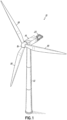
- a wind turbine generator 10 includes a tower 12, a nacelle 14 mounted atop the tower 12, a rotor hub 16 rotatably supported by the nacelle 14, and a plurality of rotor blades 18 mounted to the hub 16.
- the hub 16 is operatively coupled to a generator (not shown) housed inside the nacelle 14.
- the nacelle 14 also houses other components required for converting wind energy into electrical energy such as a gearbox, a transformer, a main shaft, a main shaft bearing, etc. (not shown).
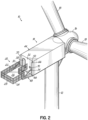
- a service platform 20, sometimes referred to as a "helihoist" is cantilevered off the aft end of the nacelle 14.
- the floor 26 of the service platform 20 may be generally L-shaped, when seen from above, having a leg portion 22 and a foot portion 24.
- the service platform 20 may have a mesh floor 26. It may have a mesh railing 28 extending around the periphery of the service platform 20, preferably, around its entire periphery.
- a gate 30 may be included in the mesh railing 28, preferably adjacent a rear wall 32 of the nacelle 14. The gate 30 may face an open area 34 between the foot portion 24 of the service platform 20 and the rear wall 32 of the nacelle 14.
- the gate may serve one or more purpose to be described below.
- the rear wall 32 of the nacelle 14 preferably has an access door 38 providing a means of ingress and egress to the nacelle 14 for workers and equipment, especially between the nacelle 14 and the platform 20.
- the nacelle 14 has an internal service floor 40 (e.g., see Figs. 4A and 4B ) that is preferably approximately coplanar with the floor 26 of the service platform 20, to facilitate such ingress and egress.
- the nacelle 14 has a frame 44 (either an exoskeleton frame or an endoskeleton frame) that includes dedicated transport fittings 46, for example tangs, ears, or lugs, on the aft end of the nacelle 14.
- the transport fittings 46 shown in the drawings are shown by way of example in the form tangs 46.
- the service platform 20 has a pair of trusses 48, one on each lateral side of the forward end of the service platform 20.
- Each truss 48 may comprise a generally upright post 50 and a lateral arm 45.
- the trusses 48 may have a generally upright L-shape when seen from the side.
- the trusses 48 connect the platform 20 to the nacelle 14.
- the trusses 48 thereby support the platform 20.
- the arms 45 of the L-shaped trusses 48 protrude in a direction away from the nacelle 14.
- the platform 20 is thereby supported aft of the nacelle 14 in such a way that it forms an extension of the nacelle 14 in a direction of the length of the nacelle 14, i.e. in what corresponds to the wind direction.
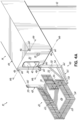
- Each truss 48 preferably has an upright post 50 and a transverse arm 45 which may comprise one or more generally lateral struts 52, 54, 56.
- An upright post 50 may be a vertical post 50.
- An arm 45 may be a generally horizontal arm 45 although one or more struts 52, 54, 56 may extend in a direction which defines an elevation angle to the arm 45. Alternatively or additionally, one or more struts 52, 54, 56 may extend in a direction which defines an declination angle to the arm 45. As illustrated, one strut 52 defines an elevation angle to the arm 45 while another strut 56 defines a declination angle to the arm 45. Still another strut 54 defines a generally horizontal direction of the arm 45.
- the floor 26 of the service platform 20 is predominantly supported on the arm, i.e. on said one or more lateral struts 52, 54, 56.
- the lateral arm of each truss 48 in turn is supported on an upright post 50.
- a support beam may extend between two trusses 48.
- a support beam may extend between the respective lateral arms of two trusses 48.
- Such a support beam may extend between one or more of the respective lateral struts 52, 54, 56 of two trusses 48.
- Such a support beam may extend between the respective lateral arms of two trusses 48 and beneath the platform floor 26.
- a support beam between two lateral arms of respective trusses 48 may thereby provide additional support or rigidity to the platform 20 construction.
- the tangs 46 and posts 50 may have respective holes 60, 62 through which pins or bolts 66 can be inserted to mount the service platform 20 to the nacelle 14.
- the tangs 46 may be in the form of so-called corner castings, e.g. ISO type corner castings.
- the posts 50 may also be provided with corresponding corner castings or the posts 50 may be provided such that they are connectable to corner castings.
- holes 60 may be corner casting holes, and the posts 50 may be connected to corner casting type tangs 46 using connectors 66 in the form of e.g. ISO type twistlock elements. Accordingly, the connection between the platform 20 and the nacelle 14 could be via corner castings on the nacelle 14, and using twistlock connectors 66 between the nacelle 14 and the platform 20.
- An electrical outlet 70 may be provided, e.g. mounted on the rear wall 32 of the nacelle 14, to provide a source of electrical power accessible to the service platform 20.
- Fig. 4A illustrates an example of a service platform 20 prior to assembly onto the nacelle 14.
- Fig. 4B illustrates a service platform 20 after assembly onto the nacelle 14.
- the service platform 20 is preferably assembled onto the nacelle 14 after the nacelle 14 is installed on the tower 12 at the installation site.
- the service platform 20 could just as well be assembled onto the nacelle 14 on the ground, first, and then the assembly of nacelle 14 and service platform 20 could be lifted up and installed, as a single unit, on the tower 12 at the installation site.
- the dedicated fittings, for example tangs, ears, or lugs 46 on the nacelle 14 serve a dual purpose: one, to attach the nacelle 14 (utilizing the tangs 46 on the forward and aft ends of the nacelle 14) to first and second transport trailers 80 towed by tow vehicle 82, and two, to attach the service platform 20 to the nacelle 14 (utilizing the tangs 46 on the aft end of the nacelle 14).
- the fittings 46 or tangs 46 may thus be referred to as nacelle transport tangs 46.
- each transport trailer 80 includes a transport frame 86 raiseable and lowerable via a lifter, for example hydraulic cylinder 88, operable between the transport frame 86 and a bed 90 of the transport trailer 80.
- Each transport frame 86 includes fittings, for example tangs, ears, or lugs 92 each with a hole 94 therethrough that, when aligned with holes 60 in tangs 46 on a respective end of the nacelle 14, can accept connectors 66 e.g. in the form of pins or bolts to secure the nacelle 14 to the transport trailers 80. Once so secured ( Fig.
- the lifters 88 can be energized to lift the nacelle 14 up off the ground or up off a supporting structure, for transport to the installation site ( Fig. 3B ). Additional details of a similar transport solution can be seen with reference to the assignee's U.S. Patent No. 7,775,753 , hereby incorporated by reference herein as if fully set forth in its entirety.
- the present disclosure envisages dual-purpose transport tangs 46 which, after transportation and delivery of a nacelle 14, e.g. to a construction site, using the transport tangs 46, are subsequently used as connection and support tangs 46 for a service platform 20 of the nacelle 14.
- a nacelle 14 between two trailers 80 each equipped with a transport frame 86 on which the nacelle 14 is supported by its transport tangs 46. Thereafter, - e.g. following delivery of the nacelle 14 to a delivery site, which may preferably or optionally be a wind turbine construction site - the nacelle 14 is disconnected from the transport trailers 80 and transport frames 86. Following this, the support trusses 48 of a service platform 20 are connected to the transport tangs 46 which are aft of the nacelle 14. The trusses 48 form a cantilever arrangement by which the platform 20 is supported. When in position at a nacelle 14, the service platform 20 is thereby supported primarily on the transport fittings 46 of the nacelle 14.
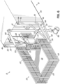
- the nacelle 14 can include a hoist 100.
- the hoist 100 may be configured to extend through the access door 38 in the rear wall 32 of the nacelle 14.
- the hoist 100 can thereby be used to transfer a load 102 horizontally from the service platform 20 into the nacelle 14 ( Fig. 5 ).
- the hoist 100 can also be configured to be slewed such that a load 102 can be transferred vertically upwardly from the ground.
- the load 102 can for example be brought up through the open area 34 between the foot portion of the service platform 20 and the rear wall 32 of the nacelle. Once the load 102 has cleared the level of the floor 26, the load 102 can be transferred horizontally, e.g.
- the hoist 100 can have a hoist arm 120 pivotally connected to a hoist base 122, and a lifter, for example a hydraulic cylinder 124, operable between the hoist arm 120 and the hoist base 122.
- the base 122 can be pivotable about a generally vertical axis to provide the slewing motion.
- Various means 126 known to those skilled in the art can be utilized to provide movement of the hoist 100 out of the nacelle 14 onto the service platform 20, such as rails, tracks, sliding or rolling floor sections, and the like.
- the service platform 20 can also function as a convenient emergency evacuation platform in the event that workers need to rapidly egress from the nacelle 14 for rescue by air ship, crane, helicopter, or the like.
- the access door 38 in the rear wall 32 may be opened such that personnel can escape to the service platform 20.
- the service platform 20 may contain other equipment, such as various chutes or escape pods (not shown), that allow personnel to evacuate from the nacelle 14 to the ground or platform adjacent the base of the tower 12.
- the nacelle and service platform of the present invention thus conveniently permit personnel and equipment to be either vertically lifted or lowered onto the service platform and then transferred horizontally from the service platform into the nacelle via the door in the rear wall of the nacelle.
- Personnel and equipment can be placed on the service platform with air ships, cranes (including self-hoisting cranes), helicopters, etc. The equipment can then be transferred horizontally from the service platform through the door in the rear wall of the nacelle and into the nacelle via the nacelle hoist.
- Personnel can simply walk from the service platform through the door in the rear wall of the nacelle and into the nacelle.
- Personnel and equipment are thus not required to be lowered down into the nacelle through a hatch in the top of the nacelle.
- the dedicated fittings of the nacelle or nacelle frame provide a convenient means of both transporting the nacelle as well as mounting the service platform on the nacelle.
- the various embodiments of the invention shown and described are merely for illustrative purposes only, as the drawings and the description are not intended to restrict or limit in any way the scope of the claims.
- the service platform may be generally rectangular, and a selectively openable/closable hatch or door may be provided in the service platform to facilitate the transport of equipment to or from the nacelle.
- the invention in its broader aspects is therefore not limited to the specific details and representative apparatus and methods shown and described.
Landscapes
- Engineering & Computer Science (AREA)
- Mechanical Engineering (AREA)
- Architecture (AREA)
- Life Sciences & Earth Sciences (AREA)
- Sustainable Development (AREA)
- Sustainable Energy (AREA)
- Chemical & Material Sciences (AREA)
- Combustion & Propulsion (AREA)
- General Engineering & Computer Science (AREA)
- Civil Engineering (AREA)
- Structural Engineering (AREA)
- Wind Motors (AREA)
Claims (13)
- Windkraftanlagengondel (14), umfassend:einen Gondelrahmen (44), der ein erstes vorderes Nabenende und ein zweites hinteres Ende aufweist;dedizierte Transportbeschläge (46) an jedem der Enden des Gondelrahmens (44), wobei die Beschläge (36) angepasst sind, um von Transportrahmen (86) an einem ersten und zweiten Transportanhänger (80) zum Halten des Gondelrahmens (44) für den Transport durch die Anhänger (80) in Eingriff genommen zu werden; undeine Serviceplattform (20), die an den Transportbeschlägen (46) am hinteren Ende des Gondelrahmens (44) montiert ist, sodass die Serviceplattform (20) vom hinteren Ende des Gondelrahmens (44) weg freitragend ist, wobei die Gondel (14) einen inneren Servicefußboden (40) aufweist und wobei ein Fußoden (26) der Serviceplattform (20) im Wesentlichen mit dem inneren Servicefußboden (40) komplanar ist.
- Gondel nach Anspruch 1, wobei ein Fußboden (26) der Serviceplattform (20) im Allgemeinen L-förmig ist, einen Schenkelabschnitt (22) und einen Fußabschnitt (24) aufweist, wobei der Schenkelabschnitt (22) an einer Rückwand (32) der Gondel (14) anliegt und der Fußabschnitt (24) von der Rückwand (32) der Gondel (14) beabstandet ist.
- Gondel nach Anspruch 2, wobei die Rückwand (32) der Gondel (14) eine Zugangstür (38) darin aufweist, die positioniert ist, um eine Verbindung zwischen der Serviceplattform (20) und dem inneren Servicefußboden (40) der Gondel (14) herzustellen, wobei die Serviceplattform (20) vorzugsweise als Notevakuierungsplattform fungiert.
- Gondel nach Anspruch 3, die weiter ein Hebezeug (100) umfasst, das konfiguriert ist, um sich durch die Zugangstür (38) hindurch aus der Gondel (14) heraus zu erstrecken, und konfiguriert ist, um geschwenkt zu werden, um zum Übertragen von Lasten (102) horizontal von der Serviceplattform (20) zur Gondel (14) und vertikal von einer Tragoberfläche nach oben zwischen dem Fußabschnitt (22) der Serviceplattform (20) und der Rückwand (32) der Gondel (14) imstande zu sein.
- Gondel nach einem vorstehenden Anspruch, wobei die Plattform (20) ein Paar Traversen (48) beinhaltet, von denen jede einen aufrechten Pfosten (50) und einen seitlichen Arm (45) aufweist, wobei der aufrechte Pfosten tragend mit den Transportbeschlägen (46) verbunden ist und wobei sich die Arme (45) von der Gondel 14 weg erstrecken, wodurch die Plattform (20) von den Traversen (48) getragen wird, die mit den Transportbeschlägen 46 verbunden sind und von diesen getragen werden.
- Gondel nach einem vorstehenden Anspruch, wobei die Rückwand (32) der Gondel (14) einen von der Serviceplattform (20) aus zugänglichen Stromanschluss (70) aufweist.
- Windkraftanlage (10), umfassend:einen Turm (12);eine Gondel (14) nach einem der Ansprüche 1-6, die oben auf dem Turm (12) montiert ist;eine Rotornabe (16), die von der Gondel (14) am vorderen Ende drehbar getragen wird; und eine Vielzahl von Rotorblättern (18), die an der Nabe (16) montiert sind.
- Verfahren zum Transportieren einer Windkraftanlagengondel (14) zu einem Aufstellungsort und Konfigurieren derselben zur Verwendung am Aufstellungsort, umfassend:Bereitstellen eines Gondelrahmens (44), der ein erstes vorderes Nabenende und ein zweites hinteres Ende aufweist;Bereitstellen von dedizierten Transportbeschlägen (46) an jedem der Enden des Gondelrahmens (44);Ineingriffbringen der Transportbeschläge (46) am vorderen Ende des Gondelrahmens (44) mit einem ersten Transportrahmen (86) an einem ersten Transportanhänger (80) und Ineingriffbringen der Transportbeschläge (46) am hinteren Ende des Gondelrahmens (44) mit einem zweiten Transportrahmen (86) an einem zweiten Transportanhänger (80);Halten des Gondelrahmens (44) über dem Boden mit dem ersten und zweiten Transportanhänger (80);Transportieren des Gondelrahmens (44) zum Aufstellungsort mit dem ersten und dem zweiten Transportanhänger (80);Entfernen des Gondelrahmens (44) vom ersten und zweiten Transportanhänger (80); undMontieren einer Serviceplattform (20) an den Transportbeschlägen (46) am hinteren Ende des Gondelrahmens (44), sodass die Serviceplattform (20) vom hinteren Ende des Gondelrahmens (44) weg freitragend ist, wobei die Gondel (14) einen inneren Servicefußboden (40) aufweist und wobei ein Fußboden (26) der Serviceplattform (20) im Wesentlichen mit dem inneren Servicefußboden (40) komplanar ist.
- Verfahren nach Anspruch 8, wobei ein Fußboden (26) der Serviceplattform (20) im Allgemeinen L-förmig ist und einen Schenkelabschnitt (22) und einen Fußabschnitt (24) aufweist, wobei der Schenkelabschnitt (22) an einer Rückwand (32) der Gondel (14) anliegt und der Fußabschnitt (24) von der Rückwand (32) der Gondel (14) beabstandet ist.
- Verfahren nach Anspruch 9, wobei die Rückwand (32) der Gondel (14) eine Zugangstür (38) darin aufweist, die positioniert ist, um eine Verbindung zwischen der Serviceplattform (20) und dem inneren Servicefußboden (40) der Gondel (14) herzustellen, wobei die Serviceplattform (20) vorzugsweise als Notevakuierungsplattform fungiert.
- Verfahren nach Anspruch 10, das weiter ein Hebezeug (100) umfasst, das konfiguriert ist, um sich durch die Zugangstür (38) hindurch aus der Gondel (14) heraus zu erstrecken, und konfiguriert ist, um geschwenkt zu werden, um zum Übertragen von Lasten (102) horizontal von der Serviceplattform (20) zur Gondel (14) und vertikal von einer Tragoberfläche nach oben zwischen dem Fußabschnitt (22) der Serviceplattform (20) und der Rückwand (32) der Gondel (14) imstande zu sein.
- Verfahren nach einem der Ansprüche 8-11, wobei die Plattform (20) ein Paar Traversen (48) beinhaltet, von denen jede einen aufrechten Pfosten (50) und einen seitlichen Arm (45) aufweist, wobei der aufrechte Pfosten tragend mit den Transportbeschlägen (46) verbunden ist und wobei sich die Arme (45) von der Gondel 14 weg erstrecken, wodurch die Plattform (20) von den Traversen (48) getragen wird, die mit den Transportbeschlägen 46 verbunden sind und von diesen getragen werden.
- Verfahren nach einem der Ansprüche 8-12, wobei die Rückwand (32) der Gondel (14) einen von der Serviceplattform (20) aus zugänglichen Stromanschluss (70) aufweist.
Applications Claiming Priority (2)
| Application Number | Priority Date | Filing Date | Title |
|---|---|---|---|
| DKPA201970842 | 2019-12-30 | ||
| PCT/DK2020/050399 WO2021136570A1 (en) | 2019-12-30 | 2020-12-21 | Wind turbine generator with service platform and associated method |
Publications (3)
| Publication Number | Publication Date |
|---|---|
| EP4085195A1 EP4085195A1 (de) | 2022-11-09 |
| EP4085195B1 true EP4085195B1 (de) | 2025-06-11 |
| EP4085195C0 EP4085195C0 (de) | 2025-06-11 |
Family
ID=74141239
Family Applications (1)
| Application Number | Title | Priority Date | Filing Date |
|---|---|---|---|
| EP20838347.1A Active EP4085195B1 (de) | 2019-12-30 | 2020-12-21 | Windturbinengenerator mit servicebühne und zugehöriges verfahren |
Country Status (4)
| Country | Link |
|---|---|
| US (1) | US12270375B2 (de) |
| EP (1) | EP4085195B1 (de) |
| ES (1) | ES3033057T3 (de) |
| WO (1) | WO2021136570A1 (de) |
Families Citing this family (6)
| Publication number | Priority date | Publication date | Assignee | Title |
|---|---|---|---|---|
| ES2947465T3 (es) * | 2018-11-15 | 2023-08-09 | Vestas Wind Sys As | Aerogenerador de rotor múltiple que comprende un sistema logístico |
| EP3885576A1 (de) * | 2020-03-27 | 2021-09-29 | Siemens Gamesa Renewable Energy A/S | Transportanordnung für windturbinenkomponenten |
| WO2023126039A1 (en) * | 2021-12-30 | 2023-07-06 | Vestas Wind Systems A/S | Tower crane for partially erecting a wind turbine and method of using same |
| WO2023126038A1 (en) * | 2021-12-30 | 2023-07-06 | Vestas Wind Systems A/S | Tower crane for partially erecting a wind turbine and method of using same |
| GB2619005B (en) | 2022-05-17 | 2024-11-27 | Subsea 7 Ltd | Mounting equipment on wind turbine structures |
| EP4306798A1 (de) | 2022-07-15 | 2024-01-17 | General Electric Renovables España S.L. | Kabinen und verfahren zur windturbinenwartung |
Family Cites Families (17)
| Publication number | Priority date | Publication date | Assignee | Title |
|---|---|---|---|---|
| US3804268A (en) * | 1970-03-16 | 1974-04-16 | Jackson Byron Inc | Marine platform structure |
| DE20205396U1 (de) * | 2001-12-29 | 2002-11-14 | Trisl, Klaus, 65197 Wiesbaden | Windmühlen-Helicopter-Landeplatz -WM-Helibase- |
| ATE415311T1 (de) | 2003-05-15 | 2008-12-15 | Vestas Wind Sys As | Transportsystem für ein windturbinenbauteil und verfahren zum transport eines windturbinenbauteils |
| CN101389855B (zh) * | 2006-02-27 | 2011-12-07 | 埃科泰克尼亚可再生能源有限公司 | 用于在风轮机上执行操作的方法和系统 |
| US20080266758A1 (en) * | 2007-04-25 | 2008-10-30 | Hurt Steven B | Mobile utilities station |
| CA2722748A1 (en) * | 2008-04-30 | 2009-11-05 | Multibrid Gmbh | Paneling of a nacelle of a wind energy installation |
| US8510943B2 (en) * | 2008-06-19 | 2013-08-20 | General Electric Company | Method for repairing a generator frame |
| EP2270330A1 (de) | 2009-06-30 | 2011-01-05 | Vestas Wind Systems A/S | Wartung einer Windturbine mittels Luftschiff |
| EP3296566B1 (de) * | 2011-02-07 | 2025-06-25 | Vestas Wind Systems A/S | Windturbine mit hubschrauberlandeplatzanordnung und verfahren zur verwendung davon |
| CN103492712B (zh) | 2011-03-30 | 2017-03-01 | 菱重维斯塔斯海上风力有限公司 | 用于风力涡轮机的机舱结构 |
| ITMI20111606A1 (it) | 2011-09-07 | 2013-03-08 | Wilic Sarl | Unita' ausiliaria per aerogeneratore |
| DE102013101239A1 (de) | 2013-02-07 | 2014-08-07 | 2-B Energy Holding B.V. | Windkraftanlage |
| WO2016164934A1 (en) * | 2015-04-09 | 2016-10-13 | Aquantis, Inc. | Floating, yawing spar current/tidal turbine |
| US9203257B1 (en) * | 2015-05-07 | 2015-12-01 | Mahmoud Mohammed Zaman | Portable wind and solar power generator |
| US10947959B2 (en) * | 2016-08-29 | 2021-03-16 | Mhi Vestas Offshore Wind A/S | Method and apparatus of performing maintenance on a wind turbine component |
| EP3372824A1 (de) * | 2017-03-07 | 2018-09-12 | Adwen GmbH | Gondelabdeckung für windturbinen |
| DK179935B1 (en) | 2017-08-29 | 2019-10-14 | Envision Energy (Denmark) Aps | Working platform system and a wind turbine and method for mounting a working platform system |
-
2020
- 2020-12-21 WO PCT/DK2020/050399 patent/WO2021136570A1/en not_active Ceased
- 2020-12-21 ES ES20838347T patent/ES3033057T3/es active Active
- 2020-12-21 EP EP20838347.1A patent/EP4085195B1/de active Active
- 2020-12-21 US US17/784,210 patent/US12270375B2/en active Active
Also Published As
| Publication number | Publication date |
|---|---|
| EP4085195A1 (de) | 2022-11-09 |
| ES3033057T3 (en) | 2025-07-30 |
| WO2021136570A1 (en) | 2021-07-08 |
| EP4085195C0 (de) | 2025-06-11 |
| US20230059355A1 (en) | 2023-02-23 |
| US12270375B2 (en) | 2025-04-08 |
Similar Documents
| Publication | Publication Date | Title |
|---|---|---|
| EP4085195B1 (de) | Windturbinengenerator mit servicebühne und zugehöriges verfahren | |
| EP3504149B1 (de) | Verfahren und vorrichtung zur durchführung von wartungsarbeiten an einer windturbinenkomponente | |
| CA2486779C (en) | Method for assembling/dismounting components of a wind power plant | |
| CN106414997B (zh) | 用于风轮发电机的包括提升设备的机舱 | |
| US8087896B2 (en) | Handling system for a wind turbine nacelle, method for vertical displacement and a wind turbine nacelle and a wind turbine nacelle | |
| EP2604850B1 (de) | Hebearm | |
| EP2433001B1 (de) | Nabe für eine windturbine | |
| CA2848822C (en) | Method and device for mounting a rotor of a wind energy plant | |
| JP6824914B2 (ja) | 風力タービンコンポーネントを移動させる方法、及び風力タービンコンポーネントを移動させる搬送システム | |
| CN1989341B (zh) | 用于风力涡轮发电机的可移动的独立起重系统 | |
| US10982659B2 (en) | Method for opening a cover portion of a wind turbine | |
| AU2003223939A1 (en) | Transportation system for a wind turbine component, vehicle for a transportation system, displacement system, method of establishing a transportation or displacement and use thereof | |
| EP3676492B1 (de) | Windturbine mit einem beweglichen behälter, in dem sich ein hebemechanismus befindet | |
| CN102464273A (zh) | 海上风机安装平台及其风机整体安装旋转抱举机构 | |
| CN105793560A (zh) | 用于维修风力涡轮机部件的固定装置 | |
| JP2020515484A (ja) | 風力タービン設置用巻き上げシステム | |
| WO2011134472A1 (en) | Handling of a crane for use in installation and service of wind turbine generator components | |
| EP2665674B1 (de) | Wartungskran für erhöhte flächen | |
| CN110217352A (zh) | 一种风电型海上登靠步桥 | |
| US20260028966A1 (en) | Service unit with crane for modular nacelle of a wind turbine and method of using same | |
| WO2025087489A1 (en) | Wind turbine having a hoisting system | |
| CN114945751A (zh) | 用于安装或移除风力涡轮机部件的方法 | |
| NZ536544A (en) | Method for assembling/dismounting components of a wind power plant |
Legal Events
| Date | Code | Title | Description |
|---|---|---|---|
| STAA | Information on the status of an ep patent application or granted ep patent |
Free format text: STATUS: UNKNOWN |
|
| STAA | Information on the status of an ep patent application or granted ep patent |
Free format text: STATUS: THE INTERNATIONAL PUBLICATION HAS BEEN MADE |
|
| PUAI | Public reference made under article 153(3) epc to a published international application that has entered the european phase |
Free format text: ORIGINAL CODE: 0009012 |
|
| STAA | Information on the status of an ep patent application or granted ep patent |
Free format text: STATUS: REQUEST FOR EXAMINATION WAS MADE |
|
| 17P | Request for examination filed |
Effective date: 20220705 |
|
| AK | Designated contracting states |
Kind code of ref document: A1 Designated state(s): AL AT BE BG CH CY CZ DE DK EE ES FI FR GB GR HR HU IE IS IT LI LT LU LV MC MK MT NL NO PL PT RO RS SE SI SK SM TR |
|
| DAV | Request for validation of the european patent (deleted) | ||
| DAX | Request for extension of the european patent (deleted) | ||
| GRAP | Despatch of communication of intention to grant a patent |
Free format text: ORIGINAL CODE: EPIDOSNIGR1 |
|
| STAA | Information on the status of an ep patent application or granted ep patent |
Free format text: STATUS: GRANT OF PATENT IS INTENDED |
|
| INTG | Intention to grant announced |
Effective date: 20250128 |
|
| GRAS | Grant fee paid |
Free format text: ORIGINAL CODE: EPIDOSNIGR3 |
|
| GRAA | (expected) grant |
Free format text: ORIGINAL CODE: 0009210 |
|
| STAA | Information on the status of an ep patent application or granted ep patent |
Free format text: STATUS: THE PATENT HAS BEEN GRANTED |
|
| AK | Designated contracting states |
Kind code of ref document: B1 Designated state(s): AL AT BE BG CH CY CZ DE DK EE ES FI FR GB GR HR HU IE IS IT LI LT LU LV MC MK MT NL NO PL PT RO RS SE SI SK SM TR |
|
| REG | Reference to a national code |
Ref country code: GB Ref legal event code: FG4D |
|
| REG | Reference to a national code |
Ref country code: CH Ref legal event code: EP |
|
| REG | Reference to a national code |
Ref country code: DE Ref legal event code: R096 Ref document number: 602020052712 Country of ref document: DE |
|
| REG | Reference to a national code |
Ref country code: IE Ref legal event code: FG4D |
|
| REG | Reference to a national code |
Ref country code: ES Ref legal event code: FG2A Ref document number: 3033057 Country of ref document: ES Kind code of ref document: T3 Effective date: 20250730 |
|
| U01 | Request for unitary effect filed |
Effective date: 20250624 |
|
| U07 | Unitary effect registered |
Designated state(s): AT BE BG DE DK EE FI FR IT LT LU LV MT NL PT RO SE SI Effective date: 20250701 |
|
| PG25 | Lapsed in a contracting state [announced via postgrant information from national office to epo] |
Ref country code: NO Free format text: LAPSE BECAUSE OF FAILURE TO SUBMIT A TRANSLATION OF THE DESCRIPTION OR TO PAY THE FEE WITHIN THE PRESCRIBED TIME-LIMIT Effective date: 20250911 Ref country code: GR Free format text: LAPSE BECAUSE OF FAILURE TO SUBMIT A TRANSLATION OF THE DESCRIPTION OR TO PAY THE FEE WITHIN THE PRESCRIBED TIME-LIMIT Effective date: 20250912 |
|
| PG25 | Lapsed in a contracting state [announced via postgrant information from national office to epo] |
Ref country code: HR Free format text: LAPSE BECAUSE OF FAILURE TO SUBMIT A TRANSLATION OF THE DESCRIPTION OR TO PAY THE FEE WITHIN THE PRESCRIBED TIME-LIMIT Effective date: 20250611 |
|
| PG25 | Lapsed in a contracting state [announced via postgrant information from national office to epo] |
Ref country code: RS Free format text: LAPSE BECAUSE OF FAILURE TO SUBMIT A TRANSLATION OF THE DESCRIPTION OR TO PAY THE FEE WITHIN THE PRESCRIBED TIME-LIMIT Effective date: 20250911 |
|
| PG25 | Lapsed in a contracting state [announced via postgrant information from national office to epo] |
Ref country code: IS Free format text: LAPSE BECAUSE OF FAILURE TO SUBMIT A TRANSLATION OF THE DESCRIPTION OR TO PAY THE FEE WITHIN THE PRESCRIBED TIME-LIMIT Effective date: 20251011 |
|
| PGFP | Annual fee paid to national office [announced via postgrant information from national office to epo] |
Ref country code: GB Payment date: 20251223 Year of fee payment: 6 |
|
| PG25 | Lapsed in a contracting state [announced via postgrant information from national office to epo] |
Ref country code: SM Free format text: LAPSE BECAUSE OF FAILURE TO SUBMIT A TRANSLATION OF THE DESCRIPTION OR TO PAY THE FEE WITHIN THE PRESCRIBED TIME-LIMIT Effective date: 20250611 |
|
| PG25 | Lapsed in a contracting state [announced via postgrant information from national office to epo] |
Ref country code: CZ Free format text: LAPSE BECAUSE OF FAILURE TO SUBMIT A TRANSLATION OF THE DESCRIPTION OR TO PAY THE FEE WITHIN THE PRESCRIBED TIME-LIMIT Effective date: 20250611 |
|
| PG25 | Lapsed in a contracting state [announced via postgrant information from national office to epo] |
Ref country code: PL Free format text: LAPSE BECAUSE OF FAILURE TO SUBMIT A TRANSLATION OF THE DESCRIPTION OR TO PAY THE FEE WITHIN THE PRESCRIBED TIME-LIMIT Effective date: 20250611 |
|
| PG25 | Lapsed in a contracting state [announced via postgrant information from national office to epo] |
Ref country code: SK Free format text: LAPSE BECAUSE OF FAILURE TO SUBMIT A TRANSLATION OF THE DESCRIPTION OR TO PAY THE FEE WITHIN THE PRESCRIBED TIME-LIMIT Effective date: 20250611 |
|
| U20 | Renewal fee for the european patent with unitary effect paid |
Year of fee payment: 6 Effective date: 20251223 |
|
| PGFP | Annual fee paid to national office [announced via postgrant information from national office to epo] |
Ref country code: ES Payment date: 20260122 Year of fee payment: 6 |
|
| PLBE | No opposition filed within time limit |
Free format text: ORIGINAL CODE: 0009261 |
|
| STAA | Information on the status of an ep patent application or granted ep patent |
Free format text: STATUS: NO OPPOSITION FILED WITHIN TIME LIMIT |
|
| REG | Reference to a national code |
Ref country code: CH Ref legal event code: L10 Free format text: ST27 STATUS EVENT CODE: U-0-0-L10-L00 (AS PROVIDED BY THE NATIONAL OFFICE) Effective date: 20260423 |