EP4084599B1 - System und verfahren zur genaueren bestimmung der gesamtqualität von ballenpflanzenmaterial - Google Patents
System und verfahren zur genaueren bestimmung der gesamtqualität von ballenpflanzenmaterial Download PDFInfo
- Publication number
- EP4084599B1 EP4084599B1 EP20793472.0A EP20793472A EP4084599B1 EP 4084599 B1 EP4084599 B1 EP 4084599B1 EP 20793472 A EP20793472 A EP 20793472A EP 4084599 B1 EP4084599 B1 EP 4084599B1
- Authority
- EP
- European Patent Office
- Prior art keywords
- plant material
- bale
- center rail
- rail structure
- infrared
- Prior art date
- Legal status (The legal status is an assumption and is not a legal conclusion. Google has not performed a legal analysis and makes no representation as to the accuracy of the status listed.)
- Active
Links
Images


Classifications
-
- G—PHYSICS
- G01—MEASURING; TESTING
- G01N—INVESTIGATING OR ANALYSING MATERIALS BY DETERMINING THEIR CHEMICAL OR PHYSICAL PROPERTIES
- G01N1/00—Sampling; Preparing specimens for investigation
- G01N1/28—Preparing specimens for investigation including physical details of (bio-)chemical methods covered elsewhere, e.g. G01N33/50, C12Q
- G01N1/286—Preparing specimens for investigation including physical details of (bio-)chemical methods covered elsewhere, e.g. G01N33/50, C12Q involving mechanical work, e.g. chopping, disintegrating, compacting, homogenising
-
- A—HUMAN NECESSITIES
- A01—AGRICULTURE; FORESTRY; ANIMAL HUSBANDRY; HUNTING; TRAPPING; FISHING
- A01F—PROCESSING OF HARVESTED PRODUCE; HAY OR STRAW PRESSES; DEVICES FOR STORING AGRICULTURAL OR HORTICULTURAL PRODUCE
- A01F15/00—Baling presses for straw, hay or the like
- A01F15/04—Plunger presses
- A01F15/042—Plungers
-
- A—HUMAN NECESSITIES
- A01—AGRICULTURE; FORESTRY; ANIMAL HUSBANDRY; HUNTING; TRAPPING; FISHING
- A01F—PROCESSING OF HARVESTED PRODUCE; HAY OR STRAW PRESSES; DEVICES FOR STORING AGRICULTURAL OR HORTICULTURAL PRODUCE
- A01F15/00—Baling presses for straw, hay or the like
- A01F15/04—Plunger presses
- A01F15/046—Plunger presses with press-boxes
-
- A—HUMAN NECESSITIES
- A01—AGRICULTURE; FORESTRY; ANIMAL HUSBANDRY; HUNTING; TRAPPING; FISHING
- A01F—PROCESSING OF HARVESTED PRODUCE; HAY OR STRAW PRESSES; DEVICES FOR STORING AGRICULTURAL OR HORTICULTURAL PRODUCE
- A01F15/00—Baling presses for straw, hay or the like
- A01F15/08—Details
-
- A—HUMAN NECESSITIES
- A01—AGRICULTURE; FORESTRY; ANIMAL HUSBANDRY; HUNTING; TRAPPING; FISHING
- A01F—PROCESSING OF HARVESTED PRODUCE; HAY OR STRAW PRESSES; DEVICES FOR STORING AGRICULTURAL OR HORTICULTURAL PRODUCE
- A01F15/00—Baling presses for straw, hay or the like
- A01F15/08—Details
- A01F15/0825—Regulating or controlling density or shape of the bale
-
- A—HUMAN NECESSITIES
- A01—AGRICULTURE; FORESTRY; ANIMAL HUSBANDRY; HUNTING; TRAPPING; FISHING
- A01F—PROCESSING OF HARVESTED PRODUCE; HAY OR STRAW PRESSES; DEVICES FOR STORING AGRICULTURAL OR HORTICULTURAL PRODUCE
- A01F29/00—Cutting apparatus specially adapted for cutting hay, straw or the like
- A01F29/09—Details
-
- G—PHYSICS
- G01—MEASURING; TESTING
- G01N—INVESTIGATING OR ANALYSING MATERIALS BY DETERMINING THEIR CHEMICAL OR PHYSICAL PROPERTIES
- G01N21/00—Investigating or analysing materials by the use of optical means, i.e. using sub-millimetre waves, infrared, visible or ultraviolet light
- G01N21/17—Systems in which incident light is modified in accordance with the properties of the material investigated
- G01N21/25—Colour; Spectral properties, i.e. comparison of effect of material on the light at two or more different wavelengths or wavelength bands
- G01N21/31—Investigating relative effect of material at wavelengths characteristic of specific elements or molecules, e.g. atomic absorption spectrometry
- G01N21/35—Investigating relative effect of material at wavelengths characteristic of specific elements or molecules, e.g. atomic absorption spectrometry using infrared light
- G01N21/3563—Investigating relative effect of material at wavelengths characteristic of specific elements or molecules, e.g. atomic absorption spectrometry using infrared light for analysing solids; Preparation of samples therefor
-
- G—PHYSICS
- G01—MEASURING; TESTING
- G01N—INVESTIGATING OR ANALYSING MATERIALS BY DETERMINING THEIR CHEMICAL OR PHYSICAL PROPERTIES
- G01N21/00—Investigating or analysing materials by the use of optical means, i.e. using sub-millimetre waves, infrared, visible or ultraviolet light
- G01N21/17—Systems in which incident light is modified in accordance with the properties of the material investigated
- G01N21/25—Colour; Spectral properties, i.e. comparison of effect of material on the light at two or more different wavelengths or wavelength bands
- G01N21/31—Investigating relative effect of material at wavelengths characteristic of specific elements or molecules, e.g. atomic absorption spectrometry
- G01N21/35—Investigating relative effect of material at wavelengths characteristic of specific elements or molecules, e.g. atomic absorption spectrometry using infrared light
- G01N21/359—Investigating relative effect of material at wavelengths characteristic of specific elements or molecules, e.g. atomic absorption spectrometry using infrared light using near infrared light
-
- G—PHYSICS
- G01—MEASURING; TESTING
- G01N—INVESTIGATING OR ANALYSING MATERIALS BY DETERMINING THEIR CHEMICAL OR PHYSICAL PROPERTIES
- G01N33/00—Investigating or analysing materials by specific methods not covered by groups G01N1/00 - G01N31/00
- G01N33/0098—Plants or trees
-
- G—PHYSICS
- G01—MEASURING; TESTING
- G01N—INVESTIGATING OR ANALYSING MATERIALS BY DETERMINING THEIR CHEMICAL OR PHYSICAL PROPERTIES
- G01N1/00—Sampling; Preparing specimens for investigation
- G01N1/28—Preparing specimens for investigation including physical details of (bio-)chemical methods covered elsewhere, e.g. G01N33/50, C12Q
- G01N1/286—Preparing specimens for investigation including physical details of (bio-)chemical methods covered elsewhere, e.g. G01N33/50, C12Q involving mechanical work, e.g. chopping, disintegrating, compacting, homogenising
- G01N2001/2873—Cutting or cleaving
-
- G—PHYSICS
- G01—MEASURING; TESTING
- G01N—INVESTIGATING OR ANALYSING MATERIALS BY DETERMINING THEIR CHEMICAL OR PHYSICAL PROPERTIES
- G01N21/00—Investigating or analysing materials by the use of optical means, i.e. using sub-millimetre waves, infrared, visible or ultraviolet light
- G01N21/17—Systems in which incident light is modified in accordance with the properties of the material investigated
- G01N21/25—Colour; Spectral properties, i.e. comparison of effect of material on the light at two or more different wavelengths or wavelength bands
- G01N21/31—Investigating relative effect of material at wavelengths characteristic of specific elements or molecules, e.g. atomic absorption spectrometry
- G01N21/35—Investigating relative effect of material at wavelengths characteristic of specific elements or molecules, e.g. atomic absorption spectrometry using infrared light
- G01N21/3563—Investigating relative effect of material at wavelengths characteristic of specific elements or molecules, e.g. atomic absorption spectrometry using infrared light for analysing solids; Preparation of samples therefor
- G01N2021/3572—Preparation of samples, e.g. salt matrices
Definitions
- the present invention relates to systems and methods for evaluating materials in bales, and more particularly, embodiments concern a system and method for preparing a sample area of a bale in order to more accurately evaluate the material incorporated into the bale.
- a swather, or windrower is an agricultural machine configured to cut plant material growing in a field and arrange the cut portions in windrows on the field in a swath to dry.
- An example swather is the Massey Ferguson WR9980 self-propelled windrower.
- the plant material may have approximately eighty-five percent moisture content.
- a rake machine may merge and turn the windrows to facilitate further drying in preparation for baling. It is common to package such plant material into bales for subsequent sale, transport, or other use.
- a baler is an agricultural machine configured to collect the windrowed and dried plant material, compress, shape, and secure it in the form of a bale.
- An example baler is the Massey Ferguson 2270XD square baler. At the time of baling, the plant material may have approximately twelve to eighteen percent moisture content.
- NIR near-infrared
- light having wavelengths between, e.g., 780 nm and 2500 nm is emitted by the instrument and at least a portion is reflected by the plant material; received, filtered, and converted to a voltage or current; and then analyzed to determine the properties of the plant material.
- NIR testing is highly dependent on the calibration methods applied to the spectra, and calibration methods and results are typically very well documented for NIR testing systems.
- Different calibration models used by different labs can be built using different wet chemistry testing procedures and results from one lab might vary as much as 30% to 50% compared to another lab which significantly effects the value and end use of the plant material.
- Another problem with this process is the long time required for the sample to reach the laboratory, the testing and analysis to be performed, and the results to be returned.
- Another problem is that the sample from one or even several bales from a field may not be representative of the quality of the many other bales from the same field. In some cases, hundreds of tons of plant material are presented by a mere fifty grams of it in the laboratory.
- bales on site It is increasingly desirable to test bales on site, but doing so requires associating calibration and filtering information with each bale and otherwise meeting the specific requirements of individual customers. For example, many larger customers, such as large dairy operations or other operations engaged in state, national, or international sales, require that testing be conducted by specific laboratories using specific processes in order to deliver a standardized product, which is not satisfied by generic calibration methods and results.
- an NIR sensor component of the NIR testing system is typically mounted either in a feeding mechanism or in a compression chamber of the baler. Due to the nature of the baling operation, the amount of time the NIR sensor is exposed to a given portion of the plant material will vary with such factors as the mass of the crop; the speed of the baler; encountering areas of the field previously baled (headlands); and the settings of the baler, such as the speed of a power take-off, the load, and a trip pressure of a stuffer. Similarly, part of the bale may be scanned as the bale exits the compression chamber, which results in a much lower sampling rate for that portion of the bale. As the aggregated plant material in an individual bale may not be homogenous in its properties, property values may be assigned to individual bales that do not reflect the actual overall quality of those bales.
- the NIR sensor component of the NIR testing system is typically positioned in the compression chamber and scans the finished bale so as to minimize effects of the baling process which may result in lower values for the properties of interest.
- NIR sensors scan an outer surface area of approximately twenty square millimeters to a depth of approximately four millimeters, which can produce unreliable results due to non-homogeneous particle size or otherwise poor representation of the overall plant material.
- Embodiments address the above-identified and other problems and limitation in the prior art by providing a system and method for preparing a sample area of a bale in order to more accurately evaluate the material incorporated into the bale.
- a system for preparing a sample area of a bale in order to more accurately evaluate the material incorporated into the bale.
- the system comprises a baler machine configured to receive a plant material and to compress, shape, and secure the plant material into a plurality of bales, and the system may include a cutter mechanism, a mixer mechanism, a compression chamber, and an NIR testing system.
- the cutter mechanism may be configured to cut a portion of the plant material in the bale into similarly-sized particles of the plant material.
- the mixer mechanism may be configured to mix the similarly-sized particles of the portion of the plant material into a homogenous aggregate of the portion of the plant material.
- the compression chamber may be configured to compress, shape and secure the homogenous aggregate of the portion of the plant material into the individual bale.
- the cutter mechanism may be positioned in the compression chamber so as to cut the portion of the plant material in the bale without damaging a binding material which secures the plant material into the bale.
- the NIR testing system may be configured to receive near-infrared radiation reflected by the homogenous aggregate of the portion of the plant material, analyze the near-infrared radiation, and generate evaluation data reflecting one or more properties of the plant material in the bale.
- the compression chamber may include a center rail structure, and the mixer mechanism may be a relief feature on the center rail structure which allows the plant material to expand and mix after cutting.
- a projecting feature on the center rail structure physically pushes against the bale to compress the homogenous aggregate of the portion of the plant material so as to present a substantially flattened surface to a near-infrared sensor of the near-infrared testing system.
- the near infrared sensor may be mounted to the center rail structure so as to cause the near-infrared sensor to exert a pressure against the surface of the bale.
- a method is provided preparing a sample area of a bale in order to more accurately evaluate the material incorporated into the bale.
- the method may be employed on a baler machine configured to receive a plant material and to compress, shape, and secure the plant material into a plurality of bales, and the method may include the following steps.
- a cutter mechanism may cut a portion of the plant material in the bale into similarly-sized particles of the plant material.
- a mixer mechanism may mix the similarly-sized particles of the portion of the plant material into a homogenous aggregate of the portion of the plant material.
- a compression mechanism may compress, shape and secure the homogenous aggregate of the portion of the plant material into the individual bale.
- the cutter mechanism may be positioned in the compression chamber so as to cut the portion of the plant material in the bale without damaging a binding material which secures the plant material into the bale.
- An NIR testing system may receive and analyze near-infrared radiation reflected by the homogenous aggregate of the portion of the plant material, and may generate evaluation data reflecting one or more properties of the plant material in the bale.
- the compression chamber may include a center rail structure, and the mixer mechanism is a relief feature on the center rail structure which is configured to allow the plant material to expand and mix after cutting.
- a projecting feature on the center rail structure physically pushes against the bale to compress the homogenous aggregate of the portion of the plant material so as to present a substantially flattened surface to a near-infrared sensor of the near-infrared testing system.
- the near infrared sensor may be mounted to the center rail structure so as to cause the near-infrared sensor to exert a pressure against the surface of the bale.
- the cutter mechanism may include one or more serrated knives mounted in a fixed position such that bale moves against and is cut by the one or more serrated knives.
- the serrated knives may be spring-loaded so as to control an amount of cutting force applied to the portion of the plant material in the bale.
- the relief feature may be further configured to allow any plant material falling from the cutter mechanism to be regathered and mixed.
- the NIR sensor may be located on a floating assembly mounted to the center rail and configured to allow for controlling the pressure exerted against the surface of the bale.
- references to “one embodiment,” “an embodiment,” or “embodiments” mean that the feature or features referred to are included in at least one embodiment of the invention.
- references to “one embodiment,” “an embodiment,” or “embodiments” in this description do not necessarily refer to the same embodiment and are not mutually exclusive unless so stated.
- a feature, component, action, step, etc. described in one embodiment may also be included in other embodiments, but is not necessarily included.
- particular implementations of the present invention can include a variety of combinations and/or integrations of the embodiments described herein.
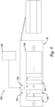
- an example baler machine 20 is shown into which embodiments of the present invention may be incorporated.
- the example baler 20 is a towed square baler, it will be appreciated that embodiments of the present invention may be incorporated into other types of balers (e.g., self-propelled, round) with few or no changes.
- the baler 20 may be configured to move over a field and collect previously cut plant material and to compress, shape, and secure the collected plant material into a plurality of bales.
- the baler 20 may generally include a pickup assembly 22, a stuffer chute assembly 24, a reciprocating plunger 26, and a baling (or compression) chamber 28.
- the pickup assembly 22 may be configured to collect the cut plant material from the field.
- the pickup assembly 22 may include a pair of ground wheels 30 that support the pickup assembly 22 as the baler 20 moves over the field.
- the stuffer chute assembly 24 may be configured to direct the collected plant material into position for incorporation into a bale.
- the stuffer chute assembly 24 may include a charge-forming duct 30 extending from an inlet opening adjacent to the pickup assembly 22 to an outlet opening into the baling chamber 28.
- the reciprocating plunger 26 may be configured to compress the plant material from the charge-forming duct 30 into a growing bale.
- the plunger 26 may be configured to reciprocate within the baling chamber 28 in repeating compression and retraction strokes across the outlet opening of the charge-forming duct 30.
- the baling chamber 28 may be configured to shape the growing bale and secure the compressed plant material in the individual bale.
- the finished bale may be ejected rearwardly to land on the field behind the baler for subsequent collection.
- the baler 20 may be hitched to a towing vehicle (not shown) by a tongue 32, and power for operating the various mechanisms (e.g., the reciprocating plunger 26) of the baler 20 may be supplied by a power take-off of the towing vehicle.
- Some embodiments may create and physically associate an identifying element containing a unique identifier with an individual bale of plant material, wherein the identifying element contains or the unique identifier can be used to find both calibration information for an NIR testing system used to evaluate one or more properties of interest of the particular plant material into the bale and the evaluation information which may be provided in terms of values for the one or more properties of interest.
- a customer for, inspector of, or other entity interested in the feedstuffs or other plant-based biomaterial incorporated into the bale can quickly and easily view the values for the one or more properties of interest for the individual bale, and can understand and be able to refute or accept these values based on how the information was processed for, e.g., a particular region or customer.
- the identifying element may be a radio-frequency identification (RFID) tag, including a microchip and an antenna, embedded or otherwise incorporated into a twine, strap, or other binding material securing the plant material into the bale.
- RFID radio-frequency identification
- the identifying element may take the form of a flat tag attached to the twine, strap, or other binding material.
- the identifying element may take the form of a bar code or similar technology.
- the identifying element may contain only the unique identifier, and the unique identifier can be used to look-up or otherwise find the calibration information and the evaluation information in one or more databases.
- the identifying element may contain the unique identifier and the calibration information and/or the evaluation information.
- the system may include an electronic transfer mechanism configured to electronically write or otherwise electronically transfer to the identifying element during the process of creating the bale the calibration and/or the evaluation information.
- the calibration information may include any one or more of an identification of a technician who calibrated the NIR testing system, a date on which the NIR testing system was calibrated, a date on which the current calibration expires, a treatment and filtering method, a calibration identifier, an intended type of plant material, and an identification of an employer of the technician, which may be AGCO Corporation or another commercial or public entity.
- Calibration information can be generated in different ways, and in particular, there are different ways to correlate spectral response and calibration.
- the NIR sensor may be an AGCO sensor and the calibration information may be generated using an AGCO calibration standard, while in another implementation, the NIR sensor may be a non-AGCO sensor and/or the calibration information may be generated using a non-AGCO calibration standard.
- the evaluation information may include any one or more of a protein content, a fiber content, a nitrate content, an ash content, a moisture content, and a relative feed value (RFV) for the plant material into the bale.
- an embodiment of a system 120 is shown for creating and physically associating an identifying element with an individual bale of plant material, wherein the identifying element includes a unique identifier and includes or can be used to find calibration and evaluation information.
- the system 120 is shown incorporated into an example operating environment.
- the system 120 may comprise some or all of the baler machine 20, an NIR testing system 122, and an identifying element securement system 124, which may function in accordance with the method 220 described below.
- the baler machine 20 may be configured to receive plant material and to compress, shape, and secure the plant material into a plurality of bales 126.
- the baler 20 may be otherwise substantially conventional in design, construction, and operation.
- the NIR testing system 122 may be configured to emit near-infrared radiation and receive a reflected response from the plant material in all or some (e.g., one of every five or fewer bales, or one of every ten or fewer bales) of the bales, analyze the near-infrared radiation, and generate evaluation information reflecting one or more properties of the plant material in each analyzed bale, and may be associated with calibration information which is relevant to the accuracy of the evaluation information.
- the NIR testing system 122 may include one or more NIR sensors 128 and a computer 130.
- the NIR sensor 128 may be mounted in or on or otherwise incorporated into the baling chamber 28 or other area of the baler 20, and may be configured to receive, filter, and convert to a voltage or current the near-infrared radiation reflected by the plant material in the bale 126, and transmit the voltage or current to the computer 130.
- the computer 130 may be located on or remotely from the baler 20, and may be configured to receive the voltage or current transmitted by the NIR sensor 128 and analyze the voltage or current to determine the properties of the plant material and generate the evaluation information reflecting those properties.
- the computer 130 may then assign a unique identifier to the bale 126, associate the calibration information for the NIR testing system 122 with the unique identifier for the bale 126, and associate the evaluation information for the bale 126 with the unique identifier for the bale 126.
- the unique identifier may be used to find the calibration information for the NIR testing system 122 in a first database 132, the unique identifier may be used to find the evaluation information in a second database 134, or the calibration and the evaluation information may be stored together in a single database.
- one or both of the calibration information and the evaluation information may be stored on a physical identifying element (described below) attached to the bale 126 by the identifying element securement system 124.
- the calibration information may include one or more of an identification of a technician who calibrated the individual NIR testing system 122, a date on which the NIR testing system 122 was calibrated, a treatment and filtering method, a calibration identifier, an intended type of plant material, and/or an identification of an employer of the technician.
- the evaluation information may include one or more of a protein content, a fiber content, a nitrate content, an ash content, a moisture content, and/or a relative feed value for the plant material in the bale 126.
- the identifying element securement 124 system may be mounted in or on or otherwise incorporated into the baling chamber 28 of the baler 20, and configured to physically secure to the individual bale 126 a physical identifying element 136 configured to physically associate the unique bale identifier with the bale 126, wherein, as discussed, the unique bale identifier is associated with and may be used to find the calibration information for the NIR testing system 122 and the evaluation information for the plant material in the bale 126.
- the physical identifying element 136 may be an RFID tag including an integrated circuit and an antenna embedded or otherwise incorporated into a top, front, or end center portion of a binding material 138 (e.g., twine, strap or similar material) which secures the bale 126.
- a binding material 138 e.g., twine, strap or similar material
- the physical identifying element 136 may take the form of a flat tag similarly attached to the binding material 138.
- the physical identifying element 136 already has the unique bale identifier stored thereon, and the identifying element securement mechanism 124 need only secure the physical identifying element 136 to the bale 126.
- the identifying element securement mechanism 124 may include an identifying element writing mechanism 140 configured to electronically write or otherwise transfer the unique bale identifier on the identifying element 136 prior to, simultaneous with, or subsequent to its securement to the bale 126.
- one or both of the calibration and the evaluation information may be stored on a physical identifying element 136, in which case the identifying element writing mechanism 140 may be further configured to electronically write or otherwise transfer one or both of the calibration information and the evaluation information to the physical identifying element 136, such that this information and/or information can be subsequently directly read from the physical identifying element 136 using, e.g., a hand-held reading device 142.
- the system 120 may include additional details discussed elsewhere herein, including those discussed below in describing the operating method 220.
- a method 220 for creating and physically associating an identifying element with an individual bale of plant material, wherein the identifying element includes a unique identifier and includes or can be used to find calibration and evaluation information.
- the method 220 may refer to an example operating environment.
- the method 220 may comprise some or all of the following steps, which may be implemented by components of the system 120 described above. As discussed, plant material may be received and compressed, shaped, and secured by a baler machine 20 into a plurality of bales 126, as shown in step 222.
- Near-infrared radiation emitted by an NIR testing system 122 and reflected by the plant material in the bale 126 may be received, filtered, and converted to a voltage or current by an NIR sensor 128 component of the NIR testing system 122, as shown in step 224, and the voltage or current may be transmitted to a computer 130 component of the NIR testing system 122, as shown in step 226.
- the NIR sensor 128 may be mounted in or on or otherwise incorporated into the baling chamber 28 or other area of the baler 20, and the computer 130 may be located on or remotely from the baler 20.
- one of every five or fewer bales may be subject to such testing, or one of every ten or fewer bales may be subject to such testing.
- the voltage or current transmitted by the NIR sensor 128 may be received and analyzed by the computer 130 to determine the properties of the plant material and generate evaluation information reflecting those properties, as shown in step 228.
- a unique identifier may be assigned by the computer 130 to the bale 126, as shown in step 230, and the calibration information for the NIR testing system 122 and the evaluation information for the bale 126 may be associated by the computer 130 with the unique identifier for the bale 126, as shown in step 232.
- the unique identifier may be used to find the calibration information for the NIR testing system 122 in a first database 132, the unique identifier may be used to find the evaluation information in a second database 134, or the calibration information and the evaluation information may be stored together in a single database.
- one or both of the calibration information and the evaluation information may be stored on a physical identifying element (described below) attached to the bale 126 by the identifying element securement system 124.
- the calibration information may include one or more of an identification of a technician who calibrated the individual NIR testing system 122, a date on which the NIR testing system 122 was calibrated, a treatment and filtering method, a calibration identifier, an intended type of plant material, and/or an identification of an employer of the technician.
- the evaluation information may include one or more of a protein content, a fiber content, a nitrate content, an ash content, a moisture content, and/or a relative feed value for the plant material in the bale 126.
- a physical identifying element 136 physically associating the unique bale identifier with the bale 126 may be physically secured to the individual bale 126 by an identifying element securement system 124, as shown in step 234.
- the identifying element securement system 124 may be mounted in or on or otherwise incorporated into the baling chamber 28 of the baler 20.
- the physical identifying element 136 may be a radio-frequency identification tag including an integrated circuit and an antenna embedded or otherwise incorporated into a top, front, or end center portion of a binding material 138 (e.g., twine, strap or similar material) which secures the bale 126.
- the physical identifying element 136 may take the form of a flat tag similarly attached to the binding material 138.
- the physical identifying element 136 already has the unique bale identifier stored thereon, and the identifying element securement mechanism 124 need only secure the physical identifying element 136 to the bale 126.
- the unique bale identifier may be electronically written or otherwise transferred to the identifying element 136 by an identifying element writing mechanism 140, as shown in step 236, prior to, simultaneous with, or subsequent to its securement to the bale 126.
- one or both of the calibration information and the evaluation information may be stored on a physical identifying element 136, in which one or both of the calibration information information and the evaluation information may be electronically written or otherwise transferred to the physical identifying element 136 by the identifying element writing mechanism 140, as shown in step 238, such that this information and/or information can be subsequently directly read from the physical identifying element 136 using, e.g., an identifying element reading device 142.
- the method 220 may include additional details discussed elsewhere herein, including those discussed above in describing the implemented system 120.
- some embodiments may evaluate individual subunits of plant material incorporated into a bale and, based thereon, assign weighted average evaluation information to the overall bale.
- the NIR sensor may be exposed to a single flake, charge, or other subunit of a bale for thirty seconds or more, and when the bale is exiting the chamber the NIR sensor may be exposed to the last few subunits for only one or two seconds.
- the results can be equally weighted in the overall evaluation information for the bale.
- a baler traveling at a constant speed may take longer to fill its pre-compression chamber resulting in longer time periods between subunits.
- a time-based overall RFV and overall value may be one hundred twenty-two (122) and $130, while a position-based overall RFV and overall value may be one hundred fifty-five (155) and $160.
- the edges of fields often show reduced quality due to increased equipment traffic, so RFV scores during headland turns are often lower.
- a time-based overall RFV and overall value may be one hundred forty-three (143) and $160, while a position-based overall RFV and overall value may be one hundred ninety-one (191) and 225.
- embodiments may weight each such spectra and/or value based on the amount of time the NIR sensor is exposed to the respective subunit of the bale, and then determines and assigns average scanned spectra and/or property values to the overall bale.
- the average property values may be substantially similar to each of the plurality of values, while in a field in which the subunits are of largely differing quality values, the average quality values may be significantly different from one or more of the individual values.
- a system 320 for evaluating individual subunits of material incorporated into a bale and, based thereon, assigning a weighted average quality value to the overall bale.
- the system 320 is shown incorporated into an example operating environment.
- the system 320 may comprise some or all of the baler machine 20 and an NIR testing system 322, which may function in accordance with the method 420 described below.
- the baler 20 may be configured to receive plant material and to compress, shape, and secure the plant material into a plurality of bales 326.
- the baler 20 may be configured to receive a plurality of subunits 327 (also referred to as charges or flakes) of the material, and to aggregate, compress, shape, and secure the plurality of subunits into individual bales 326.
- the baler 20 may be otherwise substantially conventional in design, construction, and operation.
- the NIR testing system 322 may be configured to emit near-infrared radiation and receive a reflected response from the plant material in each subunit of two or more subunits of the plurality of subunits 327 and to analyze the reflected response and generate evaluation information reflecting one or more properties of the plant material in each subunit of the two or more subunits. This process may be performed for all or some of the bales (e.g., one of every five or fewer bales, or one of every ten or fewer bales).
- the NIR testing system 322 may include one or more NIR sensors 328 and a computer 330.
- the NIR sensor 328 may be mounted in or on or otherwise incorporated into the baling chamber 28 or other area of the baler 20, and may be configured to receive, filter, and convert to a voltage or current the near-infrared radiation emitted by the plant material in each subunit of the two or more subunits of the bale 326, and transmit the voltage or current to the computer 330.
- the computer 330 may be located on or remotely from the baler 20, and may be configured to receive the voltage or current transmitted by the NIR sensor 328 and analyze the voltage or current to determine the properties of each subunit of the two or more subunits and generate the evaluation information.
- the computer 330 may be further configured to combine the evaluation information of the plant material in each subunit of the two or more subunits to produce one or more overall property values for the individual bale 326, assign the one or more overall property values to the individual bale 326, and save the one or more overall property values in a database.
- combining the subunit evaluation information may include assigning an, e.g., time-based, position-based, or size-based weight to each such subunit evaluation information and then averaging the two or more sets of subunit evaluation information to arrive at the overall evaluation information for the bale 326.
- the evaluation information may include one or more of a protein content, a fiber content, a nitrate content, an ash content, a moisture content, and a relative feed value for the plant material in the bale 326.
- the system 320 may include additional details discussed elsewhere herein, including those discussed below in describing the operating method 420.
- a method 420 for evaluating individual subunits of material incorporated in a bale and, based thereon, assigning a weighted average quality value to the overall bale.
- the method 420 may refer to an example operating environment.
- the method 420 may comprise some or all of the following steps, which may be implemented by components of the system 320 described above.
- a plurality of subunits 327 also referred to as charges or flakes
- a baler machine 20 into a plurality of bales 126, as shown in step 422.
- Near-infrared radiation emitted by an NIR testing system 322 and reflected by the plant material in each subunit of two or more subunits of the plurality of subunits 327 may be received, filtered, and converted to a voltage or current by an NIR sensor 328 component of the NIR testing system 322, as shown in step 424, and the voltage or current may be transmitted to a computer 330 component of the NIR testing system 322, as shown in step 426.
- the NIR sensor 328 may be mounted in or on or otherwise incorporated into a baling chamber 28 or other area of the baler 20, and the computer 330 may be located on or remotely from the baler 20.
- one of every five or fewer bales may be subject to such testing, or one of every ten or fewer bales may be subject to such testing.
- the voltage or current transmitted by the NIR sensor 328 may be received and analyzed by the computer 330 to determine the properties of the plant material and generate evaluation information reflecting one or more properties of the plant material in each subunit of the two or more subunits, as shown in step 428.
- the evaluation information of the plant material in each subunit of the two or more subunits may be combined by the computer 330 to produce one or more overall property values for the bale 326, as shown in step 430, and assign the one or more overall property values to the bale 326 as shown in step 432, and save the one or more overall property values in a database.
- combining the subunit evaluation information may include assigning a weight (e.g., time-based, position-based, size-based) to each such subunit evaluation information and then averaging the two or more sets of subunit evaluation information to arrive at the overall evaluation information for the bale 326.
- the subunit evaluation information and the overall evaluation information may include one or more of a protein content, a fiber content, a nitrate content, an ash content, a moisture content, and a relative feed value for the plant material in the bale 326.
- the method 420 may include additional details discussed elsewhere herein, including those discussed above in describing the implemented system 320.
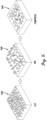
- embodiments may prepare a sample area of a bale in order to more accurately evaluate the material incorporated into the bale. More specifically, embodiments may prepare a portion of the surface of the bale by cutting, mixing, and then recompressing the plant material so as to present a more homogeneous and representative sample to the NIR sensor. Embodiments may allow the NIR sensor to, in effect, scan to a greater depth of approximately twenty (20) millimeters.
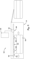
- a system 520 for preparing a sample area of a bale in order to more accurately evaluate the material incorporated into the bale.
- the system 520 is shown incorporated into an example operating environment.
- the system 520 may comprise some or all of the baler machine 20, an NIR testing system 522, and a sample preparation mechanism 524, which may function in accordance with the method 620 described below.
- the baler machine 20 may be configured to receive plant material and to compress, shape, and secure the plant material into a plurality of bales 526.
- the baler 20 may be otherwise substantially conventional in design, construction, and operation.
- the NIR testing system 522 may be configured to emit near-infrared radiation and receive a reflected response from the plant material in all or some (e.g., one of every five or fewer bales, or one of every ten or fewer bales) of the bales, analyze the reflected response, and generate evaluation information reflecting one or more properties of the plant material in each analyzed bale, and may be associated with calibration information which is relevant to the accuracy of the evaluation information.
- the NIR testing system 522 may include one or more NIR sensors 528 and a computer 530.
- the NIR sensor 528 may be mounted in or on or otherwise incorporated into the baling chamber 28 or other area of the baler 20, and may be configured to receive, filter, and convert to a voltage or current the reflected response received from the plant material in each bale 526, and transmit the voltage or current to the computer 530.
- the computer 530 may be located on or remotely from the baler 20, and may be configured to receive the voltage or current transmitted by the NIR sensor 528 and analyze the voltage or current to determine the properties of each bale 526 and generate the evaluation information.
- the evaluation information may include one or more of a protein content, a fiber content, a nitrate content, an ash content, a moisture content, and a relative feed value for the plant material in the bale 526.
- the sample preparation mechanism 524 may be configured to prepare a sample area 546 of the bale 526 which is subsequently exposed to the NIR sensor 528. As such, the sample preparation mechanism 524 may be located ahead (i.e., upstream) of the NIR sensor 528 in the baling chamber 28.
- the sample preparation mechanism 524 may include a cutter mechanism 548, a mixer mechanism 550, and a compression mechanism 552.
- the cutter, mixer, and/or compression mechanisms 548,550,552 may be one or more physically or functionally distinct or combined components/functionalities.
- the cutter mechanism 548 and the mixer mechanism 550 may be two separate component or a single component which physically or functionally combines both mechanisms.
- the cutter mechanism 548 may be configured to cut and/or grind a portion of the plant material (which consists of leaves and stems) in the sample area 546 of the bale 526 into similarly-sized particles of the plant material.
- the cutter mechanism 548 may include one or more spring-loaded serrated knives mounted in a fixed location (with the knives being otherwise shiftable against the bias of the spring) position such that sample area 548 moves against and is cut by the one or more spring-loaded serrated knives.
- the cutting/grinding element may be an auger, a grinder, or powered knives configured to produce substantially the same effect.
- the mixer mechanism 550 may be configured to mix the similarly-sized particles of the portion of the plant material into a homogenous aggregate of the portion of the plant material.
- the compression mechanism 552 may be configured to compress the homogenous aggregate of the portion of the plant material back into the bale 526 to provide a generally smooth surface for the NIR sensor 528 to scan.
- the cutter mechanism 548 may be positioned in the baling chamber 28 so as to cut and/or grind a portion of the plant material in the individual bale 526 without damaging a binding material which secures the baled plant material together.
- the baling chamber 28 may include a center rail structure 554, and the mixer mechanism 550 may be a relief feature on the center rail structure 554 which allows the cut and/or ground plant material to expand and mix.
- the relief feature may be further configured to allow any plant material falling from the cutter mechanism 548 to be gathered and mixed.
- the compression mechanism 552 may be a projecting feature on the center rail structure 554 which physically pushes against the surface of the bale 526 to compress the homogenous aggregate of the portion of the plant material so as to present a substantially flattened surface to the NIR sensor 528.
- the NIR sensor 528 may be mounted on the center rail 554 so as to cause the sensor lens to exert a pressure against the surface of the bale 526. Additionally or alternatively, the NIR sensor 528 may be located on a floating assembly mounted to the center rail 554 and configured to allow for controlling the pressure exerted against the surface of the bale 526.
- the system 120 may include additional details discussed elsewhere herein, including those discussed below in describing the operating method 220.
- a method 620 for preparing a sample area of a bale in order to more accurately evaluate the material incorporated into the bale.
- the method 620 may refer to an example operating environment.
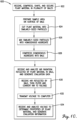
- the method 620 may comprise some or all of the following steps, which may be implemented by components of the system 520 described above. As discussed, plant material may be received, compressed, shaped and secured by a baler machine 20 into a plurality of bales 526, as shown in step 622.
- a sample area on a surface of some or all of the bales 526 may be prepared by a sample preparation mechanism 524.
- the sample preparation mechanism 524 may be mounted in or on or otherwise incorporated into the baling chamber 28 or other area of the baler 20.
- the sample preparation may include the following steps.
- a cutter mechanism 548 may cut and/or grind a portion of the plant material in the sample area 546 of the bale 526 into similarly-sized particles of the plant material, as shown in step 624.
- the cutter mechanism 548 may include one or more spring-loaded serrated knives mounted in a fixed position such that sample area 546 moves against and is cut by the one or more spring-loaded serrated knives.
- a mixer mechanism 550 may mix the similarly-sized particles of the portion of the plant material into a homogenous aggregate of the portion of the plant material, as shown in step 626.
- a compression mechanism 552 may compress the homogenous aggregate of the portion of the plant material back into the bale 526 to provide a generally smooth surface for an NIR sensor 528 to scan, as shown in step 630.
- near-infrared radiation is emitted and reflected by the plant material of the prepared sample area 546 in the bale 526, filtered, and converted to a voltage or current by the NIR sensor 528 component of an NIR testing system 522, as shown in step 630, and the voltage or current may be transmitted to a computer 530 component of the NIR testing system 422, as shown in step 632.
- the NIR sensor 528 may be mounted in or on or otherwise incorporated into the baling chamber 28 or other area of the baler 20, and the computer 530 may be located on or remotely from the baler 20.
- one of every five or fewer bales may be subject to such preparation and testing, or one of every ten or fewer bales may be subject to such preparation and testing.
- the voltage or current transmitted by the NIR sensor 528 may be received and analyzed by the computer 530 to determine the properties of the plant material and generate evaluation information, as shown in step 634.
- the evaluation information may include one or more of a protein content, a fiber content, a nitrate content, an ash content, a moisture content, and/or a relative feed value for the plant material in the bale 526.
- the method 620 may include additional details discussed elsewhere herein, including those discussed above in describing the implemented system 520.
Landscapes
- Life Sciences & Earth Sciences (AREA)
- Physics & Mathematics (AREA)
- Environmental Sciences (AREA)
- Health & Medical Sciences (AREA)
- Chemical & Material Sciences (AREA)
- Analytical Chemistry (AREA)
- Pathology (AREA)
- Spectroscopy & Molecular Physics (AREA)
- Immunology (AREA)
- General Physics & Mathematics (AREA)
- General Health & Medical Sciences (AREA)
- Biochemistry (AREA)
- Engineering & Computer Science (AREA)
- Botany (AREA)
- Medicinal Chemistry (AREA)
- Wood Science & Technology (AREA)
- Food Science & Technology (AREA)
- Preliminary Treatment Of Fibers (AREA)
- Investigating Strength Of Materials By Application Of Mechanical Stress (AREA)
- Sampling And Sample Adjustment (AREA)
- Investigating Or Analysing Materials By Optical Means (AREA)
Claims (10)
- System miteiner Ballenmaschine (20), die konfiguriert ist, um Pflanzenmaterial zu empfangen und das Pflanzenmaterial zu einem Ballen (526) zu komprimieren und zu formen und als Ballen zu sichern,einem Schneidmechanismus (548), der konfiguriert ist, um einen Teilbereich des Pflanzenmaterials in dem Ballen (526) in ähnlich bemessene Teile des Pflanzenmaterials zu schneiden;einem Mischmechanismus (550), der konfiguriert ist, um die ähnlich bemessenen Teile des Teilbereichs des Pflanzenmaterials in eine homogene Gesamtheit des Teilbereichs des Pflanzenmaterials zu mischen;einer Kompressionskammer (28), die konfiguriert ist, um die homogene Gesamtheit des Teilbereichs des Pflanzenmaterials in den individuellen Ballen (526) zu komprimieren und zu formen und in diesem zu sichern, wobei der Schneidmechanismus (548) in der Kompressionskammer (28) so angeordnet ist, dass dieser den Teilbereich des Pflanzenmaterials in dem Ballen (526) ohne eine Beschädigung eines Bindematerials, welches das Pflanzenmaterial in dem Ballen (526) sichert, schneidet; undeinem Nah-Infrarot-Testsystem (522), welches konfiguriert ist, um Nah-Infrarot-Strahlung zu empfangen, die von der homogenen Gesamtheit des Teils des Pflanzenmaterials reflektiert wird, die Nah-Infrarot-Strahlung zu analysieren und Beurteilungsdaten zu erzeugen, die eine oder mehrere Eigenschaften des Pflanzenmaterials in dem Ballen (526) widerspiegeln, dadurch gekennzeichnet, dassdie Kompressionskammer (28) eine zentrale Schienenstruktur (554) aufweist und der Mischmechanismus (550) eine Entlastungseinrichtung an der zentralen Schienenstruktur (554) ist oder aufweist, die eine Expansion des Pflanzenmaterials und eine Mischung nach dem Schneiden ermöglicht;eine vorspringende Einrichtung an der zentralen Schienenstruktur (554) physisch gegen den Ballen (526) drückt, um die homogene Gesamtheit des Teilbereichs des Pflanzenmaterials zu komprimieren für die Bereitstellung einer im Wesentlichen abgeflachten Oberfläche für einen Nah-Infrarot-Sensor (528) des Nah-Infrarot-Testsystems (522); undder Nah-Infrarot-Sensor (528) an der zentralen Schienenstruktur (554) so montiert ist, dass der Nah-Infrarot-Sensor (528) einen Druck auf die Oberfläche des Ballens (526) ausübt.
- System nach Anspruch 1, wobei der Schneidmechanismus (548) mindestens ein gezacktes oder geriffeltes Messer aufweist, welches an einer festen Position derart montiert ist, dass sich der Ballen (526) gegen dieses bewegt und durch das mindestens eine gezackte oder geriffelte Messer geschnitten wird.
- System nach Anspruch 2, wobei das gezackte oder geriffelte Messer federbeaufschlagt ist, um einen Betrag der Schneidkraft, die auf den Teilbereich des Pflanzenmaterials in dem Ballen (526) aufgebracht wird, zu steuern.
- System nach Anspruch 1, wobei die Entlastungseinrichtung des Weiteren konfiguriert ist, um zu ermöglichen, dass Pflanzenmaterial, welches von dem Schneidmechanismus (548) fällt, wieder eingesammelt und gemischt wird.
- System nach Anspruch 1, wobei der Nah-Infrarot-Sensor (528) an einer beweglichen Baugruppe angeordnet ist, die an der zentralen Schiene (554) montiert ist und konfiguriert ist zur Ermöglichung einer Steuerung des Drucks, der auf die Oberfläche des Ballens (526) ausgeübt wird.
- Verfahren miteinem Empfangen, Komprimieren, Formen und Sichern von Pflanzenmaterial mit einer Ballenmaschine (20) in einem Ballen (526);einem Schneiden eines Teilbereichs des Pflanzenmaterials in dem Ballen (526) mittels eines Schneidmechanismus (548) in ähnlich bemessene Teile des Pflanzenmaterials;einem Mischen der ähnlich bemessenen Teile des Teilbereichs des Pflanzenmaterials zu einer homogenen Gesamtheit des Teilbereichs des Pflanzenmaterials mit einem Mischmechanismus (550);einem Komprimieren, Formen und Sichern der homogenen Gesamtheit des Teilbereichs des Pflanzenmaterials mit einer Kompressionskammer (28) in den bzw. dem individuellen Ballen (526), wobei der Schneidmechanismus (548) in der Kompressionskammer (28) so positioniert ist, dass dieser den Teilbereich des Pflanzenmaterials in dem Ballen (526) ohne Beschädigung eines Bindematerials, welches das Pflanzenmaterial in dem Ballen (526) sichert, schneidet;einem Empfangen und Analysieren von Nah-Infrarot-Strahlung, die von der homogenen Gesamtheit des Teils des Pflanzenmaterials reflektiert worden ist, mittels eines Nah-Infrarot-Testsystems (522), und einem Erzeugen von Bewertungsdaten mit dem Nah-Infrarot-Testsystem (522), die mindestens eine Eigenschaft des Pflanzenmaterials des Ballens (526) betreffen, dadurch gekennzeichnet, dassdie Kompressionskammer (28) eine zentrale Schienenstruktur (554) aufweist und der Mischmechanismus (550) eine Entlastungseinrichtung an der zentralen Schienenstruktur (554) ist oder aufweist, die konfiguriert ist, um eine Expansion des Pflanzenmaterials und ein Mischen desselben nach dem Schneiden zu ermöglichen;und mit einer vorspringenden Einrichtung an der zentralen Schienenstruktur (554), welche physisch gegen den Ballen (526) drückt, um die homogene Gesamtheit des Teils des Pflanzenmaterials zu komprimieren, um eine im Wesentlichen abgeflachte Oberfläche für einen Nah-Infrarot-Sensor (528) des Nah-Infrarot-Testsystems (522) bereitzustellen; undder Nah-Infrarot-Sensor (528) an der zentralen Schienenstruktur (554) so montiert ist, dass bewirkt wird, dass der Nah-Infrarot-Sensor einen Druck auf die Oberfläche des Ballens (526) ausübt.
- Verfahren nach Anspruch 6, wobei der Schneidmechanismus (548) mindestens ein gezacktes oder geriffeltes Messer aufweist, welches an einer festen Position so montiert ist, dass sich der Ballen (526) gegen dieses bewegt wird und der Ballen durch das mindestens eine gezackte oder geriffelte Messer geschnitten wird.
- Verfahren nach Anspruch 7, wobei die gezackten oder geriffelten Messer federbeaufschlagt sind zur Steuerung des Betrags der Schneidkraft, die auf den Teil des Pflanzenmaterials in dem Ballen (526) aufgebracht wird.
- Verfahren nach Anspruch 6, wobei die Entlastungseinrichtung konfiguriert ist, um zu ermöglichen, dass Pflanzenmaterial, welches von dem Schneidmechanismus (548) fällt, wieder gesammelt und gemischt wird.
- Verfahren nach Anspruch 6, wobei der Nah-Infrarot-Sensor (528) an einer beweglichen Baugruppe angeordnet ist, die mit der zentralen Schienenstruktur (554) montiert ist und konfiguriert ist, um eine Steuerung des Drucks, der auf die Oberfläche des Ballens (526) ausgeübt wird, zu ermöglichen.
Applications Claiming Priority (2)
| Application Number | Priority Date | Filing Date | Title |
|---|---|---|---|
| US201962954789P | 2019-12-30 | 2019-12-30 | |
| PCT/IB2020/059464 WO2021136992A1 (en) | 2019-12-30 | 2020-10-08 | System and method for more accurately determining overall quality of baled plant material |
Publications (2)
| Publication Number | Publication Date |
|---|---|
| EP4084599A1 EP4084599A1 (de) | 2022-11-09 |
| EP4084599B1 true EP4084599B1 (de) | 2025-02-12 |
Family
ID=72944215
Family Applications (1)
| Application Number | Title | Priority Date | Filing Date |
|---|---|---|---|
| EP20793472.0A Active EP4084599B1 (de) | 2019-12-30 | 2020-10-08 | System und verfahren zur genaueren bestimmung der gesamtqualität von ballenpflanzenmaterial |
Country Status (5)
| Country | Link |
|---|---|
| US (1) | US12492971B2 (de) |
| EP (1) | EP4084599B1 (de) |
| AU (1) | AU2020416740A1 (de) |
| CA (1) | CA3164525A1 (de) |
| WO (1) | WO2021136992A1 (de) |
Families Citing this family (1)
| Publication number | Priority date | Publication date | Assignee | Title |
|---|---|---|---|---|
| US11980131B2 (en) * | 2020-12-29 | 2024-05-14 | Agco Corporation | Skid plate for sensor integration |
Family Cites Families (9)
| Publication number | Priority date | Publication date | Assignee | Title |
|---|---|---|---|---|
| US1399478A (en) * | 1921-01-25 | 1921-12-06 | Henry H Hardt | Indicator for baling-presses |
| US20120011820A1 (en) * | 2010-07-19 | 2012-01-19 | Agco Corporation | Header With Improved Lean Bar |
| US8567311B2 (en) * | 2010-10-28 | 2013-10-29 | Deere & Company | Control logic for applying preservative to agricultural bales |
| WO2016036749A1 (en) * | 2014-09-04 | 2016-03-10 | Agco Corporation | Baler with automated moisture measurement and preservative application |
| US9986689B2 (en) | 2014-09-22 | 2018-06-05 | Deere & Company | Utilizing crop moisture data |
| EP3232768B1 (de) | 2014-12-18 | 2020-02-05 | AGCO Corporation | Quaderballenpresse zur bereitstellung von ballengleichförmigkeit von seite zu seite |
| US10542679B2 (en) * | 2015-03-24 | 2020-01-28 | Animal Health International, Inc. | Device and method for tracking and marking baled forage material |
| US11425863B2 (en) | 2015-07-14 | 2022-08-30 | Clemson University Research Foundation | Round bale weighing method and system |
| US10785918B2 (en) * | 2017-05-18 | 2020-09-29 | Harvest Tec, Inc. | Device and method for measuring the properties of hay using near infrared spectroscopy on a large square baler |
-
2020
- 2020-10-08 WO PCT/IB2020/059464 patent/WO2021136992A1/en not_active Ceased
- 2020-10-08 EP EP20793472.0A patent/EP4084599B1/de active Active
- 2020-10-08 AU AU2020416740A patent/AU2020416740A1/en active Pending
- 2020-10-08 US US17/758,055 patent/US12492971B2/en active Active
- 2020-10-08 CA CA3164525A patent/CA3164525A1/en active Pending
Also Published As
| Publication number | Publication date |
|---|---|
| US12492971B2 (en) | 2025-12-09 |
| WO2021136992A1 (en) | 2021-07-08 |
| CA3164525A1 (en) | 2021-07-08 |
| US20230055283A1 (en) | 2023-02-23 |
| EP4084599A1 (de) | 2022-11-09 |
| AU2020416740A1 (en) | 2022-06-30 |
Similar Documents
| Publication | Publication Date | Title |
|---|---|---|
| EP4084598B1 (de) | System und verfahren zur zuweisung eines gewichteten durchschnittlichen qualitätswerts für pflanzenballenmaterial | |
| US11991956B2 (en) | System and method for preparing nir sample on baler | |
| 't Mannetje | Measuring biomass of grassland vegetation. | |
| US20220346323A1 (en) | System and method for tagging individual bales with calibration and evaluation information | |
| DE102011086021A1 (de) | Anordnung und Verfahren zur automatischen Dokumentation von Situationen bei der Feldarbeit | |
| DE102018213215A1 (de) | Sensoranordnung zur Erfassung des Anteils aufgeschlossener Körner in einem von einem Körnerprozessor bearbeiteten Häckselgutstrom und damit ausgestatteter Feldhäcksler | |
| EP4101288B1 (de) | Systeme und verfahren zum geolokalisieren und kartieren der aschekontamination in der heuproduktion | |
| EP4084600B1 (de) | Temperaturausgleichssystem und verfahren für nir-probe auf einer ballenpresse | |
| EP4084599B1 (de) | System und verfahren zur genaueren bestimmung der gesamtqualität von ballenpflanzenmaterial | |
| DE102015212107B4 (de) | Vorrichtung und Verfahren zur kontinuierlichen Bestimmung des Sandgehaltes von Futterpflanzen während des Ernteprozesses | |
| Jacobs et al. | A survey on the effect of establishment techniques, crop management, moisture availability and soil type on turnip dry matter yields and nutritive characteristics in western Victoria | |
| DE102013207281A1 (de) | Anordnung zur Inhaltsstofferfassung von Erntegut in Ballenpressen mittels Nahinfrarotspektroskopie | |
| Quick | Analysis of the combine header and design for the reduction of gathering loss in soybeans | |
| US12510502B2 (en) | Methods and systems for labeling hay bales with corrected yield | |
| Straeter | Cornrower system of stover harvest | |
| EP4014711B1 (de) | Verfahren zur kombination von at-line-messdaten und on-line-nir-messdaten zur analyse von erntegut | |
| Cherney et al. | On-farm instant quality analysis | |
| Souza et al. | Relationship between spectral indices and quality parameters of tifton 85 forage | |
| Simoneaux | Estimating Cool Season Annual Grass Forage Biomass Using UAV and Ground Based Technology | |
| Hendry | Impact of Forage Conditioner Systems on the Harvesting of Alfalfa | |
| Griggs et al. | Hay Quality Sensory Evaluation Guidelines | |
| Cash et al. | Montguide | |
| Mathur | STRAW YIELD MONITORING S | |
| SRINIVASAN | Site-Specific Measurement and Management of Grain Quality |
Legal Events
| Date | Code | Title | Description |
|---|---|---|---|
| STAA | Information on the status of an ep patent application or granted ep patent |
Free format text: STATUS: UNKNOWN |
|
| STAA | Information on the status of an ep patent application or granted ep patent |
Free format text: STATUS: THE INTERNATIONAL PUBLICATION HAS BEEN MADE |
|
| PUAI | Public reference made under article 153(3) epc to a published international application that has entered the european phase |
Free format text: ORIGINAL CODE: 0009012 |
|
| STAA | Information on the status of an ep patent application or granted ep patent |
Free format text: STATUS: REQUEST FOR EXAMINATION WAS MADE |
|
| 17P | Request for examination filed |
Effective date: 20220801 |
|
| AK | Designated contracting states |
Kind code of ref document: A1 Designated state(s): AL AT BE BG CH CY CZ DE DK EE ES FI FR GB GR HR HU IE IS IT LI LT LU LV MC MK MT NL NO PL PT RO RS SE SI SK SM TR |
|
| DAV | Request for validation of the european patent (deleted) | ||
| DAX | Request for extension of the european patent (deleted) | ||
| P01 | Opt-out of the competence of the unified patent court (upc) registered |
Effective date: 20230518 |
|
| GRAP | Despatch of communication of intention to grant a patent |
Free format text: ORIGINAL CODE: EPIDOSNIGR1 |
|
| STAA | Information on the status of an ep patent application or granted ep patent |
Free format text: STATUS: GRANT OF PATENT IS INTENDED |
|
| GRAS | Grant fee paid |
Free format text: ORIGINAL CODE: EPIDOSNIGR3 |
|
| GRAA | (expected) grant |
Free format text: ORIGINAL CODE: 0009210 |
|
| STAA | Information on the status of an ep patent application or granted ep patent |
Free format text: STATUS: THE PATENT HAS BEEN GRANTED |
|
| INTG | Intention to grant announced |
Effective date: 20241219 |
|
| AK | Designated contracting states |
Kind code of ref document: B1 Designated state(s): AL AT BE BG CH CY CZ DE DK EE ES FI FR GB GR HR HU IE IS IT LI LT LU LV MC MK MT NL NO PL PT RO RS SE SI SK SM TR |
|
| REG | Reference to a national code |
Ref country code: GB Ref legal event code: FG4D |
|
| REG | Reference to a national code |
Ref country code: CH Ref legal event code: EP |
|
| REG | Reference to a national code |
Ref country code: DE Ref legal event code: R096 Ref document number: 602020045984 Country of ref document: DE |
|
| REG | Reference to a national code |
Ref country code: IE Ref legal event code: FG4D |
|
| REG | Reference to a national code |
Ref country code: NL Ref legal event code: MP Effective date: 20250212 |
|
| PG25 | Lapsed in a contracting state [announced via postgrant information from national office to epo] |
Ref country code: RS Free format text: LAPSE BECAUSE OF FAILURE TO SUBMIT A TRANSLATION OF THE DESCRIPTION OR TO PAY THE FEE WITHIN THE PRESCRIBED TIME-LIMIT Effective date: 20250512 |
|
| PG25 | Lapsed in a contracting state [announced via postgrant information from national office to epo] |
Ref country code: FI Free format text: LAPSE BECAUSE OF FAILURE TO SUBMIT A TRANSLATION OF THE DESCRIPTION OR TO PAY THE FEE WITHIN THE PRESCRIBED TIME-LIMIT Effective date: 20250212 |
|
| PG25 | Lapsed in a contracting state [announced via postgrant information from national office to epo] |
Ref country code: PL Free format text: LAPSE BECAUSE OF FAILURE TO SUBMIT A TRANSLATION OF THE DESCRIPTION OR TO PAY THE FEE WITHIN THE PRESCRIBED TIME-LIMIT Effective date: 20250212 |
|
| PG25 | Lapsed in a contracting state [announced via postgrant information from national office to epo] |
Ref country code: ES Free format text: LAPSE BECAUSE OF FAILURE TO SUBMIT A TRANSLATION OF THE DESCRIPTION OR TO PAY THE FEE WITHIN THE PRESCRIBED TIME-LIMIT Effective date: 20250212 |
|
| REG | Reference to a national code |
Ref country code: LT Ref legal event code: MG9D |
|
| PG25 | Lapsed in a contracting state [announced via postgrant information from national office to epo] |
Ref country code: IS Free format text: LAPSE BECAUSE OF FAILURE TO SUBMIT A TRANSLATION OF THE DESCRIPTION OR TO PAY THE FEE WITHIN THE PRESCRIBED TIME-LIMIT Effective date: 20250612 Ref country code: NO Free format text: LAPSE BECAUSE OF FAILURE TO SUBMIT A TRANSLATION OF THE DESCRIPTION OR TO PAY THE FEE WITHIN THE PRESCRIBED TIME-LIMIT Effective date: 20250512 |
|
| PG25 | Lapsed in a contracting state [announced via postgrant information from national office to epo] |
Ref country code: NL Free format text: LAPSE BECAUSE OF FAILURE TO SUBMIT A TRANSLATION OF THE DESCRIPTION OR TO PAY THE FEE WITHIN THE PRESCRIBED TIME-LIMIT Effective date: 20250212 |
|
| PG25 | Lapsed in a contracting state [announced via postgrant information from national office to epo] |
Ref country code: HR Free format text: LAPSE BECAUSE OF FAILURE TO SUBMIT A TRANSLATION OF THE DESCRIPTION OR TO PAY THE FEE WITHIN THE PRESCRIBED TIME-LIMIT Effective date: 20250212 |
|
| PG25 | Lapsed in a contracting state [announced via postgrant information from national office to epo] |
Ref country code: LV Free format text: LAPSE BECAUSE OF FAILURE TO SUBMIT A TRANSLATION OF THE DESCRIPTION OR TO PAY THE FEE WITHIN THE PRESCRIBED TIME-LIMIT Effective date: 20250212 Ref country code: PT Free format text: LAPSE BECAUSE OF FAILURE TO SUBMIT A TRANSLATION OF THE DESCRIPTION OR TO PAY THE FEE WITHIN THE PRESCRIBED TIME-LIMIT Effective date: 20250612 |
|
| PG25 | Lapsed in a contracting state [announced via postgrant information from national office to epo] |
Ref country code: GR Free format text: LAPSE BECAUSE OF FAILURE TO SUBMIT A TRANSLATION OF THE DESCRIPTION OR TO PAY THE FEE WITHIN THE PRESCRIBED TIME-LIMIT Effective date: 20250513 Ref country code: BG Free format text: LAPSE BECAUSE OF FAILURE TO SUBMIT A TRANSLATION OF THE DESCRIPTION OR TO PAY THE FEE WITHIN THE PRESCRIBED TIME-LIMIT Effective date: 20250212 |
|
| REG | Reference to a national code |
Ref country code: AT Ref legal event code: MK05 Ref document number: 1765125 Country of ref document: AT Kind code of ref document: T Effective date: 20250212 |
|
| PG25 | Lapsed in a contracting state [announced via postgrant information from national office to epo] |
Ref country code: SE Free format text: LAPSE BECAUSE OF FAILURE TO SUBMIT A TRANSLATION OF THE DESCRIPTION OR TO PAY THE FEE WITHIN THE PRESCRIBED TIME-LIMIT Effective date: 20250212 |
|
| PG25 | Lapsed in a contracting state [announced via postgrant information from national office to epo] |
Ref country code: SM Free format text: LAPSE BECAUSE OF FAILURE TO SUBMIT A TRANSLATION OF THE DESCRIPTION OR TO PAY THE FEE WITHIN THE PRESCRIBED TIME-LIMIT Effective date: 20250212 |
|
| PG25 | Lapsed in a contracting state [announced via postgrant information from national office to epo] |
Ref country code: DK Free format text: LAPSE BECAUSE OF FAILURE TO SUBMIT A TRANSLATION OF THE DESCRIPTION OR TO PAY THE FEE WITHIN THE PRESCRIBED TIME-LIMIT Effective date: 20250212 |
|
| PG25 | Lapsed in a contracting state [announced via postgrant information from national office to epo] |
Ref country code: IT Free format text: LAPSE BECAUSE OF FAILURE TO SUBMIT A TRANSLATION OF THE DESCRIPTION OR TO PAY THE FEE WITHIN THE PRESCRIBED TIME-LIMIT Effective date: 20250212 |
|
| PG25 | Lapsed in a contracting state [announced via postgrant information from national office to epo] |
Ref country code: AT Free format text: LAPSE BECAUSE OF FAILURE TO SUBMIT A TRANSLATION OF THE DESCRIPTION OR TO PAY THE FEE WITHIN THE PRESCRIBED TIME-LIMIT Effective date: 20250212 |
|
| PG25 | Lapsed in a contracting state [announced via postgrant information from national office to epo] |
Ref country code: EE Free format text: LAPSE BECAUSE OF FAILURE TO SUBMIT A TRANSLATION OF THE DESCRIPTION OR TO PAY THE FEE WITHIN THE PRESCRIBED TIME-LIMIT Effective date: 20250212 Ref country code: CZ Free format text: LAPSE BECAUSE OF FAILURE TO SUBMIT A TRANSLATION OF THE DESCRIPTION OR TO PAY THE FEE WITHIN THE PRESCRIBED TIME-LIMIT Effective date: 20250212 |
|
| PG25 | Lapsed in a contracting state [announced via postgrant information from national office to epo] |
Ref country code: RO Free format text: LAPSE BECAUSE OF FAILURE TO SUBMIT A TRANSLATION OF THE DESCRIPTION OR TO PAY THE FEE WITHIN THE PRESCRIBED TIME-LIMIT Effective date: 20250212 |
|
| PG25 | Lapsed in a contracting state [announced via postgrant information from national office to epo] |
Ref country code: SK Free format text: LAPSE BECAUSE OF FAILURE TO SUBMIT A TRANSLATION OF THE DESCRIPTION OR TO PAY THE FEE WITHIN THE PRESCRIBED TIME-LIMIT Effective date: 20250212 |
|
| REG | Reference to a national code |
Ref country code: DE Ref legal event code: R097 Ref document number: 602020045984 Country of ref document: DE |
|
| PLBE | No opposition filed within time limit |
Free format text: ORIGINAL CODE: 0009261 |
|
| STAA | Information on the status of an ep patent application or granted ep patent |
Free format text: STATUS: NO OPPOSITION FILED WITHIN TIME LIMIT |
|
| PGFP | Annual fee paid to national office [announced via postgrant information from national office to epo] |
Ref country code: DE Payment date: 20251021 Year of fee payment: 6 |
|
| PGFP | Annual fee paid to national office [announced via postgrant information from national office to epo] |
Ref country code: FR Payment date: 20251030 Year of fee payment: 6 |
|
| PGFP | Annual fee paid to national office [announced via postgrant information from national office to epo] |
Ref country code: BE Payment date: 20251021 Year of fee payment: 6 |
|
| PGFP | Annual fee paid to national office [announced via postgrant information from national office to epo] |
Ref country code: IE Payment date: 20251024 Year of fee payment: 6 |
|
| 26N | No opposition filed |
Effective date: 20251113 |