EP4084553A1 - Procédé de transmission d'informations, dispositif terminal et dispositif de réseau - Google Patents
Procédé de transmission d'informations, dispositif terminal et dispositif de réseau Download PDFInfo
- Publication number
- EP4084553A1 EP4084553A1 EP20921170.5A EP20921170A EP4084553A1 EP 4084553 A1 EP4084553 A1 EP 4084553A1 EP 20921170 A EP20921170 A EP 20921170A EP 4084553 A1 EP4084553 A1 EP 4084553A1
- Authority
- EP
- European Patent Office
- Prior art keywords
- terminal device
- parameter
- offset parameter
- information
- indication information
- Prior art date
- Legal status (The legal status is an assumption and is not a legal conclusion. Google has not performed a legal analysis and makes no representation as to the accuracy of the status listed.)
- Pending
Links
Images


Classifications
-
- H—ELECTRICITY
- H04—ELECTRIC COMMUNICATION TECHNIQUE
- H04W—WIRELESS COMMUNICATION NETWORKS
- H04W72/00—Local resource management
- H04W72/04—Wireless resource allocation
- H04W72/044—Wireless resource allocation based on the type of the allocated resource
- H04W72/0446—Resources in time domain, e.g. slots or frames
-
- H—ELECTRICITY
- H04—ELECTRIC COMMUNICATION TECHNIQUE
- H04W—WIRELESS COMMUNICATION NETWORKS
- H04W56/00—Synchronisation arrangements
- H04W56/004—Synchronisation arrangements compensating for timing error of reception due to propagation delay
- H04W56/0045—Synchronisation arrangements compensating for timing error of reception due to propagation delay compensating for timing error by altering transmission time
-
- H—ELECTRICITY
- H04—ELECTRIC COMMUNICATION TECHNIQUE
- H04W—WIRELESS COMMUNICATION NETWORKS
- H04W56/00—Synchronisation arrangements
- H04W56/001—Synchronization between nodes
-
- H—ELECTRICITY
- H04—ELECTRIC COMMUNICATION TECHNIQUE
- H04B—TRANSMISSION
- H04B7/00—Radio transmission systems, i.e. using radiation field
- H04B7/14—Relay systems
- H04B7/15—Active relay systems
- H04B7/185—Space-based or airborne stations; Stations for satellite systems
- H04B7/1851—Systems using a satellite or space-based relay
- H04B7/18513—Transmission in a satellite or space-based system
-
- H—ELECTRICITY
- H04—ELECTRIC COMMUNICATION TECHNIQUE
- H04L—TRANSMISSION OF DIGITAL INFORMATION, e.g. TELEGRAPHIC COMMUNICATION
- H04L27/00—Modulated-carrier systems
- H04L27/26—Systems using multi-frequency codes
- H04L27/2601—Multicarrier modulation systems
- H04L27/2602—Signal structure
- H04L27/26025—Numerology, i.e. varying one or more of symbol duration, subcarrier spacing, Fourier transform size, sampling rate or down-clocking
-
- H—ELECTRICITY
- H04—ELECTRIC COMMUNICATION TECHNIQUE
- H04W—WIRELESS COMMUNICATION NETWORKS
- H04W56/00—Synchronisation arrangements
- H04W56/003—Arrangements to increase tolerance to errors in transmission or reception timing
-
- H—ELECTRICITY
- H04—ELECTRIC COMMUNICATION TECHNIQUE
- H04W—WIRELESS COMMUNICATION NETWORKS
- H04W72/00—Local resource management
- H04W72/20—Control channels or signalling for resource management
- H04W72/23—Control channels or signalling for resource management in the downlink direction of a wireless link, i.e. towards a terminal
-
- H—ELECTRICITY
- H04—ELECTRIC COMMUNICATION TECHNIQUE
- H04W—WIRELESS COMMUNICATION NETWORKS
- H04W76/00—Connection management
- H04W76/10—Connection setup
- H04W76/11—Allocation or use of connection identifiers
-
- H—ELECTRICITY
- H04—ELECTRIC COMMUNICATION TECHNIQUE
- H04W—WIRELESS COMMUNICATION NETWORKS
- H04W84/00—Network topologies
- H04W84/02—Hierarchically pre-organised networks, e.g. paging networks, cellular networks, WLAN [Wireless Local Area Network] or WLL [Wireless Local Loop]
- H04W84/04—Large scale networks; Deep hierarchical networks
- H04W84/06—Airborne or Satellite Networks
Definitions
- the present disclosure relates to communication technology, and more particularly, to an information transmission method, a terminal device, and a network device.
- a terminal device In a New Radio (NR) system of a terrestrial communication network, due to the round-trip propagation delay, a terminal device needs to consider the impact of Timing Advance (TA) when transmitting signals. For example, when the terminal device is scheduled to transmit on slot n, in order for the time at which the signal arrives at a network device to be the uplink slot n of the network device, the terminal device needs to transmit the signal in advance.
- TA Timing Advance
- the propagation delay of the signal is usually smaller than 1 ms.
- NTN Non Terrestrial Network
- the propagation delay of the signal could be very high.
- the propagation delay can be in the order of hundreds of milliseconds. Since the signal propagation delay in the NTN system is greatly increased compared with the signal propagation delay in the terrestrial NR system, the timing relationship of information transmission in the terrestrial NR system cannot be applied to the NTN system, nor can it be applied to other application scenarios or other systems which are not NTN systems but have similar conditions.
- the embodiments of the present disclosure provide an information transmission method, a terminal device, and a network device, such that the timing relationship of communication between the network device and the terminal device can be accurate.
- An embodiment of the present disclosure provides an information transmission method.
- the method is applied in a terminal device and includes: receiving, by the terminal device, first indication information; and determining, by the terminal device, a first offset parameter value based on the received first indication information.
- the first offset parameter value is used to determine a timing relationship of transmission.
- An embodiment of the present disclosure provides an information transmission method.
- the method is applied in a network device and includes: transmitting, by the network device, first indication information to a terminal device.
- the first indication information is used for the terminal device to determine a first offset parameter value based on the first indication information, and the first offset parameter value is used for the terminal device to determine a timing relationship of transmission.
- An embodiment of the present disclosure further provides a terminal device.
- the terminal device includes: a receiving module configured to receive first indication information; and a determining module configured to determine a first offset parameter value based on the received first indication information.
- the first offset parameter value is used to determine a timing relationship of transmission.
- An embodiment of the present disclosure further provides a network device.
- the network device includes: a transmitting module configured to transmit first indication information to a terminal device.
- the first indication information is used for the terminal device to determine a first offset parameter value based on the first indication information, and the first offset parameter value is used for the terminal device to determine a timing relationship of transmission.
- a terminal device in an embodiment of the present disclosure, includes a processor and a memory.
- the memory has a computer program stored thereon, and the processor is configured to invoke and execute the computer program stored in the memory to implement the above information transmission method.
- a network device in an embodiment of the present disclosure, includes a processor and a memory.
- the memory has a computer program stored thereon, and the processor is configured to invoke and execute the computer program stored in the memory to implement the above information transmission method.
- a chip in an embodiment of the present disclosure, includes a processor configured to invoke and execute a computer program from a memory, to enable a device provided with the chip to implement the above information transmission method.
- a computer-readable storage medium has a computer program stored thereon.
- the computer program enables a computer to implement the above information transmission method.
- a computer program product includes computer program instructions that cause a computer to implement the above information transmission method.
- a computer program causes a computer to implement the above information transmission method.
- the network device can configure and/or indicate the offset parameter value for information transmission to the terminal device, and the terminal device can determine the offset parameter value according to the configuration and/or indication from the network device, and use the offset parameter value to determine the timing relationship of transmission, so as to achieve communication between network device and terminal device with accurate timing relationship.
- GSM Global System of Mobile Communication
- CDMA Code Division Multiple Access
- WCDMA Wideband Code Division Multiple Access
- GPRS General Packet Radio Service
- LTE Long Term Evolution
- LTE-A Advanced Long Term Evolution
- NR New Radio
- NTN Non-Terrestrial Network
- UMTS Universal Mobile Telecommunication System
- WLAN Wireless Local Area Networks
- WiFi Wireless Fidelity
- D2D Device to Device
- M2M Machine to Machine
- MTC Machine Type Communication
- V2V Vehicle to Vehicle
- V2X V2X communication
- the communication system of an embodiment of the present disclosure may also be applied to a Carrier Aggregation (CA) scenario, a Dual Connectivity (DC) scenario, a Standalone (SA) network deployment scenario, and the like.
- CA Carrier Aggregation
- DC Dual Connectivity
- SA Standalone
- the embodiments of the present disclosure are described in conjunction with a network device and a terminal device.
- the terminal device may refer to a User Equipment (UE), an access terminal, a user unit, a user station, a mobile station, a remote station, a remote terminal, a mobile device, a user terminal, a terminal, a wireless communication device, a user agent, or a user device.
- UE User Equipment
- the terminal device may be a station (ST) in a WLAN, a cellular phone, a cordless phone, a Session Initiation Protocol (SIP) phone, a Wireless Local Loop (WLL) station, a Personal Digital Assistant (PDA) device, a handheld device or a computing device having a wireless communication function, another processing device connected to a wireless modem, a vehicle-mounted device, a wearable device, a terminal device in the next generation communication system (e.g., NR network), or a terminal device in a future evolved Public Land Mobile Network (PLMN), etc.
- ST station
- WLAN Wireless Local Loop
- PDA Personal Digital Assistant
- the terminal device can be deployed on land, including indoor or outdoor, handheld, worn, or vehicle-mounted, deployed on water (e.g., on a ship), or deployed in the air (e.g., on an airplane, a balloon, a satellite, etc.).
- the terminal device may be a mobile phone, a tablet computer (Pad), a computer with a wireless transceiver function, a Virtual Reality (VR) terminal device, an Augmented Reality (AR) terminal device, a wireless terminal in industrial control, a vehicle-mounted terminal device, a wireless terminal in self driving, a wireless terminal device in remote medical, a wireless terminal device in smart grid, a wireless terminal device in transportation safety, a wireless terminal device in smart city, a wireless terminal device in smart home, a wearable terminal device, etc.
- a mobile phone a tablet computer (Pad), a computer with a wireless transceiver function
- VR Virtual Reality
- AR Augmented Reality
- wireless terminal in industrial control a vehicle-mounted terminal device
- a wireless terminal in self driving a wireless terminal device in remote medical
- a wireless terminal device in smart grid a wireless terminal device in transportation safety
- a wireless terminal device in smart city a wireless terminal device in smart home, a wearable terminal device, etc.
- the terminal device involved in the embodiments of the present disclosure may also be referred to as terminal, User Equipment (UE), access terminal device, vehicle-mounted terminal, industrial control terminal, UE unit, UE station, mobile station, mobile, remote station, remote terminal device, mobile device, UE terminal device, wireless communication device, UE proxy or UE device, etc.
- the terminal device may be stationary or mobile.
- the terminal device may also be a wearable device.
- the wearable device also known as wearable smart device, is a general term for wearable devices that are intelligently designed and developed from everyday wear, such as glasses, gloves, watches, clothes, and shoes, by applying wearable technologies.
- a wearable device is a portable device that can be directly worn on or integrated into a user's clothes or accessories.
- a wearable device is not only a kind of hardware device, but can also provide powerful functions based on software support, data interaction, and cloud interaction.
- wearable smart devices may include full-featured, large-sized devices that can provide full or partial functions without relying on smart phones, such as smart watches or smart glasses, and devices that only focus on a certain type of application function and need to cooperate with other devices such as smart phones for use, such as various smart bracelets and smart jewelries for physical sign monitoring.
- the network device may be a device communicating with mobile devices.
- the network device may be an Access Point (AP) in a WLAN, a base station such as Base Transceiver Station (BTS) in a GSM system or a CDMA system, a base station such as NodeB (NB) in a WCDMA system, a base station such as Evolutional Node (eNB or eNodeB) in an LTE system, or a relay station, an access point, a vehicle-mounted device, a wearable device, a network device or base station (e.g., gNB) in an NR network, or a network device in a future evolved PLMN
- AP Access Point
- BTS Base Transceiver Station
- NB NodeB
- eNB Evolutional Node
- LTE Long Term Evolutional Node
- the network device may have mobile characteristics, e.g., the network device may be a mobile device.
- the network device may be a satellite or a balloon station.
- the satellite may be a Low Earth Orbit (LEO) satellite, a Medium Earth Orbit (MEO) satellite, a Geostationary Earth Orbit (GEO) satellite, a High Elliptical Orbit (HEO) satellite, etc.
- the network device may also be a base station provided on a location such as land or water.
- the network device may provide services for a cell, and the terminal device may communicate with the network device over transmission resources, e.g., frequency domain resources or frequency spectral resources, used in the cell.
- the cell may be a cell corresponding to the network device (e.g., base station).
- the cell may belong to a macro base station or a base station corresponding to a small cell.
- the small cell here may include a metro cell, a micro cell, a pico cell, a femto cell, or the like. These small cells have characteristics such as small coverage and low transmission power, and are suitable for providing high-rate data transmission services.
- FIG. 1 exemplarily shows one network device 1100 and two terminal devices 1200.
- the wireless communication system 1000 may include multiple network devices 1100, and the coverage of each network device 1100 may include other numbers of terminal devices.
- the embodiment of the present disclosure is not limited to this.
- the wireless communication system 1000 as shown in FIG. 1 may also include other network entities such as Mobility Management Entity (MME) or Access and Mobility Management Function (AMF).
- MME Mobility Management Entity
- AMF Access and Mobility Management Function
- system and “network” may often be used interchangeably herein.
- the term “and/or” as used herein only represents a relationship between correlated objects, including three relationships.
- a and/or B may mean A only, B only, or both A and B.
- the symbol “/” as used herein represents an “or” relationship between the correlated objects preceding and succeeding the symbol.
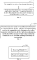
- Case 1 Referring to FIG. 2 , the downlink (DL) slot is aligned with the uplink (UL) slot on the base station (gNB) side.
- the UE in order to align the uplink transmission of the UE on the terminal side with the uplink slot on the base station side, the UE needs to transmit in advance according to the TA value. The higher the propagation delay is, and the larger the TA will be accordingly.
- the transmission timing relationship in the NTN system can be determined with reference to the transmission timing relationship in the NR system by introducing an offset parameter.
- Case 2 Referring to FIG. 3 , there is an offset value TS between the downlink slot and the uplink slot on the base station (gNB) side.
- the UE in order to align the uplink transmission of the UE on the terminal side with the uplink transmission, the UE also needs to transmit in advance according to the TA value, which is relatively small.
- the base station side needs a complex scheduling scheme to process the transmission scheduling timing relationship.
- the information transmission timing relationship on the terminal side and the base station side can be enhanced by introducing an offset parameter.
- the timing relationship in the NR system may include one or more of the following cases:
- the embodiments of the present disclosure use the offset parameter value K offset to enhance the timing relationship in the communication system, or apply the offset parameter value K offset to the timing relationship, such that in various communication scenarios, the communication between the network device and the terminal device can be performed with accurate timing relationship.
- the use of the offset parameter value K offset to enhance the timing relationship may include one or more of the following cases:
- the network device needs to notify the terminal device of the value of the offset parameter value K offset , and the terminal device can apply the offset parameter value K offset to the timing relationship after receiving and determining it.
- the network device needs to notify the terminal device of the value of the offset parameter value K offset , and the terminal device can apply the offset parameter value K offset to the timing relationship after receiving and determining it.
- an embodiment of the present disclosure provides an information transmission method, which is used in a terminal device to determine an offset parameter value, such that communication between the network device and the terminal device can be performed with accurate timing relationship.
- FIG. 4 is a schematic flowchart of an information transmission method applied in a terminal device according to an embodiment of the present disclosure. The method includes at least part of the following content.
- the terminal device receives first indication information.
- the terminal device determines a first offset parameter value based on the received first indication information.
- the first offset parameter value is used to determine a timing relationship of transmission.
- the terminal device can determine the first offset parameter value based on the indication from the network device, use the first offset parameter value to determine the timing relationship of transmission, and enhance the timing relationship in the communication system by introducing the offset parameter value, so as to achieve communication between the network device and the terminal device with accurate timing relationship.
- FIG. 5 is a schematic flowchart illustrating an information transmission method applied in a network device according to an embodiment of the present disclosure. The method includes at least part of the following content.
- the network device transmits first indication information to a terminal device.
- the first indication information is used for the terminal device to determine a first offset parameter value based on the first indication information
- the first offset parameter value is used for the terminal device to determine a timing relationship of transmission.
- the network device can indicate the first offset parameter value to the terminal device via the first indication information, such that the terminal device can determine the timing relationship of transmission based on the first offset parameter value.
- the first offset parameter value may include a value of K offset .
- the first offset parameter value may include an offset value between a downlink slot and an uplink slot that are associated with a same slot number at the network device side.
- the first offset parameter value may include the value of the offset value TS between the downlink slot and the uplink slot on the base station (gNB) side in the above Case 2.
- the information transmission may be an uplink transmission, a downlink transmission, and/or a sidelink transmission.
- the first offset parameter value being used to determine the timing relationship of transmission may include at least one of: the first offset parameter value being used to determine the timing relationship of uplink transmission, the first offset parameter value being used to determine the timing relationship of downlink transmission, and the first offset parameter value being used to determine the timing relationship of sidelink transmission.
- the first indication information may be carried in at least one of Radio Resource Control (RRC) signaling, MAC CE, and DCI.
- RRC Radio Resource Control
- the first indication information may be transmitted via a system message, e.g., a Master Information Block (MIB) message or a System Information Block (SIB) message.
- MIB Master Information Block
- SIB System Information Block
- the first indication information may be transmitted over a Physical Broadcast Channel (PBCH), e.g., in the payload of the PBCH.
- PBCH Physical Broadcast Channel
- the first indication information may be transmitted via a Random Access Response (RAR) grant message.
- RAR Random Access Response
- the first indication information may be transmitted via a DCI for scheduling an RAR grant.
- the offset parameter may be in units of at least one of symbol, slot, subframe, half-frame, radio frame (or frame for short), millisecond, and second.
- the terminal device in the embodiment of the present disclosure may determine the first offset parameter value based on the first indication information in various schemes, which will be described in detail below.
- the terminal device may determine, based on a first mapping, an offset parameter value corresponding to the first indication information as the first offset parameter value.
- the first mapping includes a correspondence between at least one indication information and at least one offset parameter value.
- Table 1 exemplarily shows the first mapping, which includes the correspondence between four entries of indication information and four offset parameter values.
- Table 1 Indication Information Offset Parameter Value 00 Offset Parameter 0 01 Offset Parameter 1 10 Offset Parameter 2 11 Offset Parameter 3
- the first offset parameter value is the offset parameter 0 or if the first indication information is 11, the first offset parameter value is the offset parameter 3.
- the first mapping may be predetermined or configured by a network device.
- the terminal device can determine the first mapping, and after receiving the first indication information, determine the offset parameter value corresponding to the first indication information, so as to determine the timing relationship of transmission.
- the first indication information may include first parameter information, and the terminal device may determine, based on a determined second mapping, an offset parameter value corresponding to the first parameter information in the first indication information as the first offset parameter value.
- the second mapping may include a correspondence between at least one parameter information and at least one offset parameter value.
- the first indication information may indicate a first parameter, and the terminal device may determine the first offset parameter value based on the first parameter.
- the second mapping may be predetermined or configured by a network device.
- the first parameter information may include at least one of the following types of parameters: subcarrier spacing, cell identification, beam identification, Synchronization Signal Block (SSB) identification, satellite scenario, satellite altitude, transmission type, whether a Radio Resource Control (RRC) parameter configuration is completed.
- the terminal device is in an initial access stage before the RRC parameter configuration is completed, and is in a connected state after the RRC configuration is completed.
- the satellite scenario may include a at least one of a Low Earth Orbit (LEO) scenario, a Medium Earth Orbit (MEO) scenario, a Geostationary Earth Orbit (GEO) scenario, or a High Elliptical Orbit (HEO) scenario.
- the satellite altitude may be 600 km or 1200 km.
- the transmission type includes at least one of: Physical Uplink Shared Channel (PUSCH) transmission, Physical Uplink Control Channel (PUCCH) transmission, third-step message (MSG3) PUSCH transmission, Medium Access Control (MAC) Control Element (CE) command transmission, Channel State Information (CSI) reference resource, aperiodic channel Sounding Reference Signal (SRS) transmission, or Physical Random Access Channel (PRACH) transmission.
- the CSI reference resource may refer to a resource used for CSI-RS transmission for CSI measurement or reporting.
- different first parameters may correspond to different second mappings.
- two examples will be given below for explanation.
- Example 1 The first parameter information includes subcarrier spacing configuration information, and the second mapping is shown in Table 2.
- Table 2 Subcarrier Spacing Configuration ⁇ Offset Parameter Value 0 Offset Parameter 0 1 Offset Parameter 1 2 Offset Parameter 2 3 Offset Parameter 3
- the subcarrier spacing configurations ⁇ correspond to the values of the subcarrier spacings. For example, when ⁇ is 0, the corresponding subcarrier spacing is 15 kHz, and when ⁇ is 1, the corresponding subcarrier spacing is 30 kHz.
- the first parameter information indicates 0, and the terminal device determines, based on Table 2, that the offset parameter value is the offset parameter 0.
- the subcarrier spacing configuration is a subcarrier spacing configuration of an uplink Bandwidth Part (BWP).
- BWP Bandwidth Part
- Example 2 The first parameter information includes configuration information of satellite scenario and satellite altitude, and the second mapping is shown in Table 3.
- Table 3 Satellite Scenario And Satellite Altitude Offset Parameter Value LEO 600 km Offset Parameter 0 LEO 1200 km Offset Parameter 1 GEO Offset Parameter 2
- the first parameter information indicates that the satellite scenario is LEO and the satellite altitude is 600 km. Based on Table 3, the terminal device determines that the offset parameter value is the offset parameter 0. When the satellite altitude is 1200 km, the terminal device determines that the offset parameter value is the offset parameter 1.
- the first parameter information indicates that the satellite scenario is GEO, and the offset parameter value is offset parameter 2.
- the altitude of the GEO satellite is fixed (35786 km), so the GEO scenario only corresponds to the offset parameter 2 in the mapping table.
- the terminal device can determine the second mapping, and after receiving the first indication information, obtain the first parameter information in the first indication information, and then determine the offset parameter value corresponding to the first parameter information, which is used to determine the timing relationship of transmission.
- the first indication information may include first jointly coded information
- the terminal device may determine, based on a third mapping, an offset parameter value corresponding to the first jointly coded information in the first indication information as the first offset parameter value.
- the first jointly coded information is generated by jointly encoding values of parameters in a first parameter group.
- the first parameter group includes at least two types of parameters, and the at least two types of parameters include an offset parameter.
- the third mapping includes a correspondence between at least one jointly coded information and at least one value of each type of parameter in the first parameter group.
- the first joint encoding information is generated by jointly encoding each parameter in the first parameter group
- the value of each type of parameter in the first parameter group, including the offset parameter value, corresponding to the first joint encoding information can be obtained based on the third mapping.
- the first parameter group may include SSB identification (ID), subcarrier spacing, and offset parameter, and the third mapping is shown in Table 4.
- Table 4 Jointly Coded Information SSB ID ⁇ Offset Parameter Value 000 SSB ID 0 0 Offset Parameter 0 001 SSB ID 0 1 Offset Parameter 1 010 SSB ID 0 2 Offset Parameter 2 011 SSB ID 0 3 Offset Parameter 3 100 SSB ID 1 0 Offset Parameter 4 101 SSB ID 1 1 Offset Parameter 5 110 SSB ID 1 2 Offset Parameter 6 111 SSB ID 1 3 Offset Parameter 7
- the terminal device can determine that the offset parameter value is the offset parameter 1 based on Table 4, and can also determine that the SSB identification is 0 and the subcarrier spacing configuration is 1. If the first indication information includes the jointly coded information 110, the terminal device can determine that the offset parameter value is the offset parameter 6 based on Table 4, and can also determine that the SSB identification is 1 and the subcarrier spacing configuration is 2.
- the first parameter group may include transmission type and offset parameter, and the third mapping is shown in Table 5.
- Table 5 Jointly Coded Information Transmission Type Offset Parameter Value 00 PUSCH and/or PUCCH Offset Parameter 0 01 CSI reference resource and/or aperiodic SRS Offset Parameter 1 10 PRACH and/or MSG3 PUSCH Offset Parameter 2 11 MAC CE command Offset Parameter 3
- the terminal device determines, based on Table 5, that the offset parameter is the offset parameter 0, and the transmission type is PUSCH and/or PUCCH.
- the first parameter group may include cell identification, satellite scenario, satellite altitude, and offset parameter
- the third mapping is shown in Table 6.
- Table 6 Jointly Coded Information Cell Identification Satellite Scenario & Satellite Altitude Offset Parameter Value 00 Cell 0 LEO 1200 km Offset Parameter 0 01 Cell 1 LEO 1200 km Offset Parameter 1 10 Cell 2 GEO Offset Parameter 2 11 Cell 3 GEO Offset Parameter 3
- the terminal device determines, based on Table 6, that the offset parameter value is the offset parameter 1, the cell identification is 1, the satellite scenario is LEO, and the satellite altitude is 1200 km. Accordingly, the terminal device can determine that for Cell 1, the information of the network device includes the satellite scenario of LEO, the satellite altitude of 1200 km, and the offset parameter used to determine the timing relationship being the offset parameter of 1.
- the first parameter group may be predetermined or configured by a network device.
- the third mapping may be predetermined or configured by a network device.
- the terminal device can determine the third mapping, and after receiving the first indication information, obtain the first jointly coded information in the first indication information, and then determine the offset parameter value corresponding to the first jointly coded information, which is used to determine the timing relationship of transmission. Additionally, information of the parameters other than the offset parameter in the first jointly coded information can also be obtained.
- the terminal device may be configured with a plurality of parameter mapping tables each including a correspondence between a value of at least one type of parameter and at least one offset parameter value.
- the first indication information may include second parameter information.
- the second parameter information indicates that at least one mapping table (e.g., a first parameter mapping table) corresponding to the second parameter information is to be selected from the plurality of parameter mapping tables, and then the terminal device may determine the first offset parameter value according to the selected first parameter mapping table.
- the second parameter information includes a plurality of the second parameter values, and the plurality of mapping tables correspond to the plurality of the second parameter values, respectively.
- the terminal device selects a parameter mapping table corresponding to the second parameter value from the plurality of parameter mapping tables.
- the plurality of mapping tables may correspond to a plurality of satellite scenarios (e.g., LEO 600 scenario, LEO 1200 scenario, and GEO scenario), respectively, and the second parameter information may indicate that at least one of the plurality of mapping tables is to be selected, e.g., the second parameter information may indicate that the terminal device is to select the mapping table corresponding to the satellite scenario of the LEO 600 scenario.
- the second parameter information may indicate that the terminal device is to select the mapping table corresponding to the satellite scenario of the LEO 600 scenario.
- each mapping table includes a correspondence between at least one parameter information and at least one offset parameter value.
- the terminal device may determine the first offset parameter value based on the selected mapping table.
- the selected parameter mapping table may include the correspondence between subcarrier spacing configurations and offset parameter values, and the terminal device can determine the corresponding offset parameter value based on the current subcarrier spacing configuration, as the first offset parameter value.
- the first indication information may further include third parameter information, which corresponds to an offset parameter value in at least one of the plurality of parameter mapping tables. If the terminal device selects a parameter mapping table corresponding to the second parameter value from the plurality of parameter mapping tables, it can further determine the first offset parameter value from the selected parameter mapping table based on the third parameter information.
- the second parameter information may indicate that the terminal device is to select the mapping table corresponding to the satellite scenario of the LEO 600 scenario
- the third parameter information may indicate the subcarrier spacing configuration 0 then the terminal device can determine, from the mapping table corresponding to the LEO 600 scenario, the first offset parameter value corresponding to the subcarrier spacing configuration 0.
- the first indication information may include third parameter information, which indicates that the first offset parameter value is to be determined from a first parameter mapping table.
- the first parameter mapping table may correspond to the first offset parameter value.
- the first parameter mapping table may be determined according to the second parameter information, or may be determined in other ways, such as predetermined or determined according to other parameters, and the embodiment is not limited to any of these examples.
- the plurality of parameter mapping tables may be predetermined or configured by a network device.
- the plurality of parameter mapping tables may include a mapping table of a first satellite scenario and a mapping table of a second satellite scenario.
- a mapping table of a first satellite scenario may be included.
- more satellite scenario mapping tables may be included.
- Different parameter mapping tables correspond to different satellite application scenarios.
- Table 7-1, Table 7-2, and Table 7-3 show parameter mapping tables of three satellite scenarios, respectively.
- Table 7-1 Subcarrier Spacing Configuration ⁇ (LEO 600 scenario) Offset Parameter Value 0 Offset Parameter 0 1 Offset Parameter 1 2 Offset Parameter 2 3 Offset Parameter 3 Table 7-2
- Subcarrier Spacing Configuration ⁇ (LEO 1200 scenario) Offset Parameter Value 0 Offset Parameter 4 1 Offset Parameter 5 2 Offset Parameter 6 3 Offset Parameter 7 Table 7-3
- Subcarrier Spacing Configuration ⁇ (GEO scenario) Offset Parameter Value 0 Offset Parameter 8 1 Offset Parameter 9 2 Offset Parameter 10 3 Offset Parameter 11
- Table 7-1 is the parameter mapping table corresponding to the LEO satellite scenario with an altitude of 600 km
- Table 7-2 is the parameter mapping table corresponding to the LEO satellite scenario with an altitude of 1200 km
- Table 7-3 is the parameter mapping corresponding to the GEO satellite scenario.
- the terminal device can determine to select, for example, Table 7-2 from the above three mapping tables according to the second parameter information in the first indication information, and determine the offset parameter value according to the subcarrier spacing configuration in Table 7-2.
- the terminal device can select, for example, Table 7-2 from the above three mapping tables according to other parameter information, such as the satellite scenario of the network device, and determine the offset parameter value according to the subcarrier spacing configuration in Table 7-2.
- the plurality of parameter mapping tables may include a mapping table of a first cell and a mapping table of a second cell.
- a mapping table of a first cell may be included in the plurality of parameter mapping tables.
- more cell mapping tables may be included in the plurality of parameter mapping tables. Different parameter mapping tables correspond to different cells.
- Table 8-1 and Table 8-2 show parameter mapping tables of two cells, respectively.
- Table 8-1 Subcarrier Spacing Configuration ⁇ (Serving Cell) Offset Parameter Value 0 Offset Parameter 0 1 Offset Parameter 1 2 Offset Parameter 2 3 Offset Parameter 3
- Table 8-2 Subcarrier Spacing Configuration ⁇ (Neighboring Cell) Offset Parameter Value 0 Offset Parameter 4 1 Offset Parameter 5 2 Offset Parameter 6 3 Offset Parameter 7
- Table 8-1 and Table 8-2 may be tables configured by a network device.
- Table 8-1 is a mapping table of a serving cell
- Table 8-2 is a mapping table of a neighboring cell.
- the terminal can select Table 8-1 as the first parameter mapping table. If the terminal is currently being handed over from the serving cell to the neighboring cell, it can select Table 8-2 as the first parameter mapping table. Further, the first offset parameter value may be determined from the selected table according to the third parameter information.
- the terminal device can be configured with a plurality of parameter mapping tables, and after receiving the first indication information, obtain the second parameter information in the first indication information, select the parameter mapping table corresponding to the second parameter information, and then determine the corresponding offset parameter value according to the current value of the parameter corresponding to the parameter mapping table, so as to determine the timing relationship of transmission.
- the terminal device can obtain the third parameter information in the first indication information, and determine the offset parameter value corresponding to the third parameter information, in the selected parameter mapping table, so as to determine the timing relationship of transmission.
- the network device can indicate the offset parameter of the current cell to the terminal device of the current cell (i.e., the serving cell), and can also indicate the offset parameter of the neighboring cell to the terminal device of the current cell.
- the two cases will be described in detail below.
- the terminal device first receives first indication information from a first network device.
- the terminal device belongs to a first cell, and the first network device belongs to the first cell.
- the first network device completes indicating of the offset parameter of the first cell to the terminal device of the first cell (i.e., the current cell, or the serving cell).
- the terminal device first receives first indication information from a first network device.
- the terminal device belongs to a first cell, and the first network device belongs to the first cell.
- the terminal device determines a first offset parameter value based on the received first indication information.
- the first offset parameter value includes an offset parameter value corresponding to a second cell.
- the terminal device performs uplink transmission, e.g., transmitting an uplink channel/signal, to a second network device according to the obtained first offset parameter value.
- the second network device belongs to the second cell.
- the first cell and the second cell are neighboring cells of each other.
- the terminal device is a terminal device in the first cell
- the first network device is a network device in the first cell
- the second network device is a network device in the second cell.
- the first cell is the serving cell of the terminal device
- the second cell is a neighboring cell of the terminal device.
- the first network device transmits the offset parameter corresponding to the second cell to the terminal device, such that the terminal device can perform uplink transmission to the second network device according to the offset parameter, for example, performing a cell handover procedure according to the offset parameter.
- the first network device completes indicating of the offset parameter of the second cell (i.e., the neighboring cell) to the terminal device of the first cell (i.e., the current cell or the serving cell).
- the terminal device before the RRC parameter configuration is completed, can determine the mapping according to a predetermined relationship, such as a protocol agreement. Alternatively, after the RRC parameter configuration is completed, the terminal device can determine the mapping according to the configuration parameters of the network device.
- the mapping may include at least one of the first mapping, the second mapping, the third mapping, and the plurality of parameter mapping tables.
- the terminal device before the RRC parameter configuration is completed, can determine the first parameter group according to a predetermined relationship, such as a protocol agreement.
- the terminal device can determine the first parameter group according to the configuration parameters of the network device.
- the offset parameter value when the first indication information indicates an offset parameter value, if the offset parameter value corresponds to a subcarrier spacing, the offset parameter value may be determined based on the subcarrier spacing.
- the first offset parameter value is in units of slot or symbol.
- the offset parameter values in each mapping involved in the embodiments of the present disclosure may be configured according to Round Trip Time (RTT) of a cell.
- RTT Round Trip Time
- the offset parameter may be determined from the maximum RTT and/or the minimum RTT of the cell.
- the maximum RTT of the cell may be 40 ms
- the network device may determine the offset parameter value according to the RTT to be 4 radio frames, 8 radio half-frames or 40 subframes, where the length of a radio frame is 10 ms, the length of a radio half-frame is 5 ms, and the length of a subframe is 1 ms.
- the offset parameter is 40 slots.
- the length of one slot is 1 ms.
- the offset parameter is 80 slots.
- the length of one slot is 0.5 ms.
- the offset parameter is 160 slots.
- the length of one slot is 0.25 ms.
- the offset parameter is 320 slots.
- the length of one slot is 0.125 ms.
- the minimum RTT of the cell may be 55 ms
- the network device may determine the offset parameter according to the RTT to be 6 radio frames, 11 radio half-frames, or 55 subframes.
- the offset parameter is 55 slots.
- the offset parameter is 110 slots.
- the offset parameter is 220 slots.
- the offset parameter is 440 slots.
- the terminal device can determine the first offset parameter value based on the indication from the network device, and use the first offset parameter value to determine the timing relationship of transmission.
- the timing relationship in the communication system can be enhanced by introducing the offset parameter value, such that the communication between the network device and the terminal device can be achieved with accurate timing relationship.
- the terminal device is configured with two parameter mapping tables, as shown in Table 9-1 and Table 9-2.
- Table 9-1 is the mapping table of the serving cell, including offset parameter values corresponding to four beams.
- Table 9-2 is the mapping table of the neighboring cell, including offset parameter values corresponding to two beams.
- Table 9-1 SSB ID (Serving Cell) Offset Parameter Value SSB ID 0 K offset0 SSB ID 1 K offset1 SSB ID 2 K offset2 SSB ID 3 K offset3
- Table 9-2 SSB ID (Neighboring Cell) Offset Parameter Value K offset SSB ID 0 K offset4 SSB ID 1 K offset5
- the terminal device receives the first indication information transmitted by the first network device, and selects the parameter mapping table of the serving cell shown in Table 9-1 according to the first indication information. Then, since the beam corresponding to the current downlink communication between the terminal device and the first network device is a beam determined based on the SSB ID 1, it can be determined that the current SSB ID is the SSB ID 1, then the terminal device can determine that the first offset parameter value corresponding to the uplink communication with the first network device is K offset1 .
- the first network device is a network device in the serving cell.
- one or more of the following transmission timing relationships can be determined based on the first offset parameter value K offset1 :
- the configuration of the terminal device in this embodiment is similar to the configuration of the terminal device in Embodiment 1, including two parameter mapping tables shown in Table 9-1 and Table 9-2.
- Embodiment 1 selects the parameter mapping table of the neighboring cell shown in Table 9-2 according to the first indication information.
- the terminal device determines to transmit a PRACH on a PRACH resource corresponding to the SSB ID 0 of the second cell, and thus determines the first offset parameter value corresponding to the uplink communication with the second network device as K offset4 corresponding to the SSB ID 0 in Table 9-2.
- the second network device is a network device in the second cell.
- K offset4 may be the value of the offset parameter in Case 1, or K offset4 may be the value of the offset value TS between the downlink slot and the uplink slot on the base station (gNB) side in Case 2.
- the terminal device searches for the SSB of the first cell, and determines a common Timing Advance (TA) of the first cell according to a system message transmitted by the first network device of the first cell.
- TA Timing Advance
- the terminal device transmits a PRACH to the first network device according to the TA.
- the first network device After receiving the PRACH transmitted by the terminal device, the first network device transmits an RAR grant scheduled by first DCI to the terminal device.
- the first DCI includes the first indication information, or the RAR grant includes the first indication information.
- the terminal device determines the offset parameter value K offset1 corresponding to the first indication information as the first offset parameter value.
- the terminal device transmits a MSG3 PUSCH on the PUSCH resource scheduled by the RAR grant according to the first offset parameter value K offset1 .
- the terminal device searches for the SSB of the first cell, and receives a system message transmitted by the first network device of the first cell.
- the system message includes the first indication information.
- the terminal device determines, based on the first mapping, the first offset parameter value K offset0 corresponding to the first indication information as the offset parameter value of the first cell.
- the terminal device transmits a PRACH to the first network device according to the first offset parameter value K offset0 .
- the first network device After receiving the PRACH transmitted by the terminal device, the first network device transmits an RAR grant scheduled by the first DCI to the terminal device.
- the terminal device transmits a MSG3 PUSCH on the PUSCH resource scheduled by the RAR grant according to the first offset parameter K offset0 .
- the embodiments of the present disclosure further provide one or more terminal devices.
- the terminal device(s) in the embodiments of the present disclosure may implement any one of the above methods.
- the terminal device 100 includes:
- the determining module 120 may be configured to determine, based on a first mapping, an offset parameter value corresponding to the first indication information as the first offset parameter value.
- the first mapping may include a correspondence between at least one indication information and at least one offset parameter value.
- the first indication information may include first parameter information.
- the determining module 120 may be configured to determine, based on a second mapping, an offset parameter value corresponding to the first parameter information in the first indication information as the first offset parameter value.
- the second mapping may include a correspondence between at least one parameter information and at least one offset parameter value.
- the first indication information may include first jointly coded information.
- the determining module 120 may be configured to determine, based on a third mapping, an offset parameter value corresponding to the first jointly coded information in the first indication information as the first offset parameter value, and/or the network device may configure a first parameter group for the terminal device.
- the first jointly coded information is generated by jointly encoding values of parameters in the first parameter group.
- the first parameter group includes at least two types of parameters.
- the at least two types of parameters include an offset parameter.
- the third mapping includes a correspondence between at least one jointly coded information and at least one value of each type of parameter in the first parameter group.
- the terminal device 100 may further include: an obtaining module 130 configured to obtain the value of each type of parameter corresponding to the first jointly coded information based on the third mapping.
- the first parameter group may include an offset parameter.
- the first parameter group may further include at least one of the following types of parameters: subcarrier spacing, cell identification, beam identification, SSB identification, satellite scenario, satellite altitude, transmission type, whether an RRC parameter configuration is completed.
- the terminal device may be configured with a plurality of parameter mapping tables each including a correspondence between a value of at least one type of parameter and at least one offset parameter value.
- the first indication information may include second parameter information.
- the determining module 120 may be configured to select a first parameter mapping table corresponding to the second parameter information from the plurality of parameter mapping tables; and determine the first offset parameter value according to the first parameter mapping table.
- the terminal device may be configured with a plurality of parameter mapping tables each comprising a correspondence between a value of at least one type of parameter and at least one offset parameter value.
- the first indication information may include third parameter information.
- the determining module 120 may be configured to determine the first offset parameter value from a first parameter mapping table based on the third parameter information.
- the plurality of parameter mapping tables may include a mapping table of a first cell and a mapping table of a second cell.
- the plurality of parameter mapping tables may include a mapping table of a first satellite scenario and a mapping table of a second satellite scenario.
- the terminal device may belong to the first cell
- a first network device may belong to the first cell
- the first indication information may be transmitted from the first network device.
- the terminal device 100 may further include: a transmission module 140 configured to perform uplink transmission to the first network device based on the first offset parameter value.
- the terminal device may belong to a first cell, a first network device may belong to the first cell, and the first indication information may be transmitted from the first network device.
- a second network device may belong to a second cell, and the first offset parameter value may be an offset parameter value corresponding to the second cell.
- the transmitting module 140 may be further configured to perform uplink transmission to the second network device based on the first offset parameter value.
- the embodiments of the present disclosure further provide one or more network devices.
- the network device(s) in the embodiment of the present disclosure may implement any one of the above methods.
- an embodiment of the present disclosure provides a network device 200.
- the network device 200 includes: a transmitting module 210 configured to transmit first indication information to a terminal device.
- the first indication information is used for the terminal device to determine a first offset parameter value based on the first indication information, and the first offset parameter value is used for the terminal device to determine a timing relationship of transmission.
- the network device 200 may further include a configuring module 220.
- the configuring module 220 may be configured to configure a first mapping for the terminal device.
- the first mapping may include a correspondence between at least one indication information and at least one offset parameter value.
- the first indication information may include first parameter information.
- the configuring module 220 may be further configured to configure a second mapping for the terminal device.
- the second mapping may include a correspondence between at least one parameter information and at least one offset parameter value.
- the first parameter information may include at least one of the following types of parameters: subcarrier spacing, cell identification, beam identification, Synchronization Signal Block (SSB) identification, satellite scenario, satellite altitude, transmission type, whether a Radio Resource Control (RRC) parameter configuration is completed.
- SSB Synchronization Signal Block
- RRC Radio Resource Control
- the first indication information may include first jointly coded information.
- the configuring module 220 may be further configured to a third mapping for the terminal device.
- the third mapping may include a correspondence between at least one jointly coded information and at least one value of each type of parameter in a first parameter group.
- the jointly coded information may be generated by jointly encoding values of parameters in the first parameter group.
- the first parameter group may include an offset parameter.
- the first parameter group may further include at least one of the following types of parameters: subcarrier spacing, cell identification, beam identification, SSB identification, satellite scenario, satellite altitude, transmission type, whether an RRC parameter configuration is completed.
- the first indication information may include second parameter information.
- the configuration module 220 may be further configured to a plurality of parameter mapping tables for the terminal device.
- the second parameter information corresponds to at least one of the plurality of parameter mapping tables.
- the first indication information may further include third parameter information.
- the configuring module 220 may be further configured to configure a plurality of parameter mapping tables for the terminal device.
- the third parameter information corresponds to an offset parameter value in at least one of the plurality of parameter mapping tables.
- FIG. 9 is a schematic diagram showing a structure of a communication device 600 according to an embodiment of the present disclosure.
- the communication device 600 includes a processor 610, and the processor 610 can invoke and execute a computer program from a memory to implement the method according to any of the embodiments of the present disclosure.
- the communication device 600 may further include a memory 620.
- the processor 610 can invoke and execute a computer program from the memory 620 to implement the method according to any of the embodiments of the present disclosure.
- the memory 620 may be a separate device independent of the processor 610, or may be integrated in the processor 610.
- the communication device 600 may further include a transceiver 630.
- the processor 610 can control the transceiver 630 to communicate with other devices, and in particular to transmit information or data to other devices or receive information or data transmitted by other devices.
- the transceiver 630 may include a transmitter and a receiver.
- the transceiver 630 may further include one or more antennas.
- the communication device 600 may be the network device in the embodiment of the present disclosure, and the communication device 600 can perform corresponding procedures implemented by the network device in the method according to any of the embodiments of the present disclosure. Details thereof will be omitted here for simplicity.
- the communication device 600 may be the terminal device in the embodiment of the present disclosure, and the communication device 600 can perform corresponding procedures implemented by the terminal device in the method according to any of the embodiments of the present disclosure. Details thereof will be omitted here for simplicity.
- FIG. 10 is a schematic diagram showing a structure of a chip 700 according to an embodiment of the present disclosure.
- the chip 700 shown in FIG. 12 includes a processor 710, and the processor 710 can invoke and execute a computer program from a memory to implement the method in the embodiment of the present disclosure.
- the chip 700 may further include a memory 720.
- the processor 710 can invoke and execute a computer program from the memory 720 to implement the method in the embodiment of the present disclosure.
- the memory 720 may be a separate device independent from the processor 710, or may be integrated in the processor 710.
- the chip 700 may further include an input interface 730.
- the processor 710 can control the input interface 730 to communicate with other devices or chips, and in particular, obtain information or data transmitted by other devices or chips.
- the chip 700 may further include an output interface 740.
- the processor 710 can control the output interface 740 to communicate with other devices or chips, and in particular, output information or data to other devices or chips.
- the chip can be applied to the network device in the embodiment of the present disclosure, and the chip can implement the corresponding processes implemented by the network device in the various methods of the embodiments of the present disclosure. For the sake of brevity, details thereof will be omitted here.
- the chip can be applied to the terminal device in the embodiment of the present disclosure as shown in FIG. 6 , FIG. 7, or FIG. 9 , and the chip can implement the corresponding process implemented by the terminal device in each method of the embodiment of the present disclosure.
- the chip can implement the corresponding process implemented by the terminal device in each method of the embodiment of the present disclosure.
- details thereof will be omitted here.
- the chip in the embodiment of the present disclosure may be referred to as a system-level chip, a system-chip, a chip system, or a system-on-chip.
- the processor as described above can be a general purpose processor, a Digital Signal Processor (DSP), a Field Programmable Gate Array (FPGA), an Application Specific Integrated Circuit (ASIC), or another programmable logic device, a transistor logic device, or a discrete hardware component.
- DSP Digital Signal Processor
- FPGA Field Programmable Gate Array
- ASIC Application Specific Integrated Circuit
- the above general purpose processor may be a microprocessor or any conventional processor.
- the memory as described above may be a volatile memory or a non-volatile memory, or may include both volatile and non-volatile memories.
- the non-volatile memory may be a Read-Only Memory (ROM), a Programmable ROM (PROM), an Erasable PROM (EPROM), an Electrically EPROM (EEPROM), or a flash memory.
- the volatile memory may be a Random Access Memory (RAM).
- the above memories are exemplary only, rather than limiting the present disclosure.
- the memory in the embodiment of the present disclosure may also be a Static RAM (SRAM), a Dynamic RAM (DRAM), a Synchronous DRAM (SDRAM), a Double Data Rate SDRAM (DDR SDRAM), an Enhanced SDRAM (ESDRAM), a Synch Link DRAM (SLDRAM), or a Direct Rambus RAM (DR RAM). That is, the memory in the embodiments of the present disclosure is intended to include, but not limited to, these and any other suitable types of memories.
- SRAM Static RAM
- DRAM Dynamic RAM
- SDRAM Synchronous DRAM
- DDR SDRAM Double Data Rate SDRAM
- ESDRAM Enhanced SDRAM
- SLDRAM Synch Link DRAM
- DR RAM Direct Rambus RAM
- FIG. 11 is a schematic block diagram of a communication system 800 according to an embodiment of the present disclosure.
- the communication system 800 includes a terminal device 810 and a network device 820.
- the network device 820 transmits first indication information to the terminal device 810.
- the terminal device 810 receives the first indication information, and determines a first offset parameter value based on the received first indication information.
- the first offset parameter value is used to determine a timing relationship of transmission.
- the terminal device 810 can be configured to implement the corresponding functions implemented by the terminal device in the method according to any of the embodiments of the present disclosure
- the network device 820 can be configured to implement the corresponding functions implemented by the network device in the method according to any of the embodiments of the present disclosure.
- details thereof will be omitted here.
- the above embodiments may be implemented in whole or in part by software, hardware, firmware, or any combination thereof.
- software When implemented in software, it can be implemented in whole or in part in the form of a computer program product.
- the computer program product includes one or more computer instructions.
- the computer may be a general purpose computer, a special purpose computer, a computer network, or any other programmable device.
- the computer instructions may be stored in a computer-readable storage medium, or transmitted from one computer-readable storage medium to another.
- the computer instructions may be transmitted from a website, computer, server, or data center to another website, computer, server, or data center via wired communication (e.g., coaxial cable, optical fiber, or Digital Subscriber Line (DSL)) or wireless communication (e.g., infrared, wireless, microwave, etc.).
- wired communication e.g., coaxial cable, optical fiber, or Digital Subscriber Line (DSL)
- wireless communication e.g., infrared, wireless, microwave, etc.
- the computer-readable storage medium may be any available medium that can be accessed by a computer, or a data storage device including one or more available mediums, such as a server, a data center, etc.
- the available mediums may include magnetic mediums (e.g., floppy disks, hard disks, magnetic tapes), optical medium (e.g., Digital Video Disc (DVD)), or semiconductor mediums (e.g., Solid State Disk (SSD)), etc.
- magnetic mediums e.g., floppy disks, hard disks, magnetic tapes
- optical medium e.g., Digital Video Disc (DVD)
- semiconductor mediums e.g., Solid State Disk (SSD)
- the numbering of the above processes does not necessarily mean their execution order.
- the execution order of the processes should be determined based on their functions and internal logics.
- the implementations of the embodiments of the present disclosure are not limited to any specific execution order.
Landscapes
- Engineering & Computer Science (AREA)
- Computer Networks & Wireless Communication (AREA)
- Signal Processing (AREA)
- Physics & Mathematics (AREA)
- Astronomy & Astrophysics (AREA)
- General Physics & Mathematics (AREA)
- Aviation & Aerospace Engineering (AREA)
- Mathematical Physics (AREA)
- Mobile Radio Communication Systems (AREA)
Applications Claiming Priority (1)
| Application Number | Priority Date | Filing Date | Title |
|---|---|---|---|
| PCT/CN2020/076656 WO2021168661A1 (fr) | 2020-02-25 | 2020-02-25 | Procédé de transmission d'informations, dispositif terminal et dispositif de réseau |
Publications (2)
| Publication Number | Publication Date |
|---|---|
| EP4084553A1 true EP4084553A1 (fr) | 2022-11-02 |
| EP4084553A4 EP4084553A4 (fr) | 2023-01-04 |
Family
ID=77490572
Family Applications (1)
| Application Number | Title | Priority Date | Filing Date |
|---|---|---|---|
| EP20921170.5A Pending EP4084553A4 (fr) | 2020-02-25 | 2020-02-25 | Procédé de transmission d'informations, dispositif terminal et dispositif de réseau |
Country Status (6)
| Country | Link |
|---|---|
| US (1) | US20220394650A1 (fr) |
| EP (1) | EP4084553A4 (fr) |
| JP (1) | JP7441960B2 (fr) |
| KR (1) | KR20220146498A (fr) |
| CN (2) | CN114731672A (fr) |
| WO (1) | WO2021168661A1 (fr) |
Families Citing this family (6)
| Publication number | Priority date | Publication date | Assignee | Title |
|---|---|---|---|---|
| US11812431B2 (en) * | 2020-08-12 | 2023-11-07 | Qualcomm Incorporated | Methods and apparatus for monitoring DL communication with timing offsets |
| CN115776363A (zh) * | 2021-09-07 | 2023-03-10 | 大唐移动通信设备有限公司 | 一种时间单元确定方法、终端、网络设备和存储介质 |
| CN116584129A (zh) * | 2021-09-30 | 2023-08-11 | 北京小米移动软件有限公司 | 一种随机接入方法、通信装置及通信设备 |
| CN114301519B (zh) * | 2021-12-31 | 2023-03-24 | 浙江时空道宇科技有限公司 | 数据传输方法、装置、设备及存储介质 |
| CN118338440A (zh) * | 2023-01-12 | 2024-07-12 | 华为技术有限公司 | 通信方法和通信装置 |
| CN118540792A (zh) * | 2023-02-21 | 2024-08-23 | 华为技术有限公司 | 通信方法及装置 |
Family Cites Families (12)
| Publication number | Priority date | Publication date | Assignee | Title |
|---|---|---|---|---|
| CN101572577B (zh) * | 2008-04-30 | 2012-11-28 | 电信科学技术研究院 | 一种实现上行发送定时提前的方法和装置 |
| US20160295597A1 (en) * | 2013-07-26 | 2016-10-06 | Intel IP Corporation | Signaling interference information for user equipment assistance |
| EP4362570A3 (fr) * | 2016-09-19 | 2024-07-31 | ASUSTek Computer Inc. | Procédé et appareil de gestion d'une avance de la temporisation pour la transmission en liaison montante dans un système de communications sans fil |
| US11159347B2 (en) * | 2017-05-04 | 2021-10-26 | Lg Electronics Inc. | Method for transmitting and receiving signal by means of beam in wireless communication system, and apparatus for said method |
| CN109327884B (zh) * | 2017-07-31 | 2021-02-12 | 华为技术有限公司 | 通信方法、网络设备和中继设备 |
| US11102777B2 (en) * | 2017-11-10 | 2021-08-24 | Telefonaktiebolaget Lm Ericsson (Publ) | Timing advance offset for uplink-downlink switching in new radio |
| WO2019097922A1 (fr) * | 2017-11-16 | 2019-05-23 | ソニー株式会社 | Dispositif terminal, dispositif de station de base, et procédé |
| CN110167133B (zh) * | 2018-02-13 | 2021-08-13 | 华为技术有限公司 | 一种上行同步方法及装置 |
| WO2019160737A1 (fr) * | 2018-02-14 | 2019-08-22 | Idac Holdings, Inc. | Procédés et procédures de gestion harq dans des réseaux non terrestres basés sur nr |
| CN110557782B (zh) * | 2018-06-01 | 2021-03-05 | 上海朗帛通信技术有限公司 | 一种用于无线通信的通信节点中的方法和装置 |
| WO2020019182A1 (fr) * | 2018-07-25 | 2020-01-30 | Oppo广东移动通信有限公司 | Appareil et procédé de transmission de signal, dispositif terminal, et dispositif de réseau |
| CN110535677B (zh) * | 2018-12-12 | 2023-05-02 | 中兴通讯股份有限公司 | 一种定时信息配置方法、装置和系统 |
-
2020
- 2020-02-25 CN CN202080082832.6A patent/CN114731672A/zh active Pending
- 2020-02-25 CN CN202211090189.9A patent/CN115413045B/zh active Active
- 2020-02-25 EP EP20921170.5A patent/EP4084553A4/fr active Pending
- 2020-02-25 KR KR1020227030841A patent/KR20220146498A/ko unknown
- 2020-02-25 JP JP2022551048A patent/JP7441960B2/ja active Active
- 2020-02-25 WO PCT/CN2020/076656 patent/WO2021168661A1/fr unknown
-
2022
- 2022-08-01 US US17/878,352 patent/US20220394650A1/en active Pending
Also Published As
| Publication number | Publication date |
|---|---|
| KR20220146498A (ko) | 2022-11-01 |
| EP4084553A4 (fr) | 2023-01-04 |
| US20220394650A1 (en) | 2022-12-08 |
| CN114731672A (zh) | 2022-07-08 |
| JP2023521544A (ja) | 2023-05-25 |
| WO2021168661A1 (fr) | 2021-09-02 |
| JP7441960B2 (ja) | 2024-03-01 |
| CN115413045B (zh) | 2024-06-04 |
| CN115413045A (zh) | 2022-11-29 |
Similar Documents
| Publication | Publication Date | Title |
|---|---|---|
| EP4084553A1 (fr) | Procédé de transmission d'informations, dispositif terminal et dispositif de réseau | |
| US20220159732A1 (en) | Random access method and device | |
| WO2022016376A1 (fr) | Procédé de traitement d'informations d'accès aléatoire, terminal et dispositif réseau | |
| US20230095079A1 (en) | Method for wireless communication, terminal device, and network device | |
| US20230095158A1 (en) | Wireless communication method, terminal device and network device | |
| CN116192337A (zh) | 无线通信的方法及装置 | |
| WO2022040867A1 (fr) | Procédé d'accès aléatoire, dispositif terminal et dispositif réseau | |
| CN113518420B (zh) | 通信方法以及通信装置 | |
| US20240023076A1 (en) | Method for channel estimation, terminal device, and network device | |
| WO2019100340A1 (fr) | Procédé d'accès aléatoire, procédé de rapport de spectre, équipement terminal et dispositif réseau | |
| US20230283361A1 (en) | Wireless communication method, terminal device and network device | |
| US20230239875A1 (en) | Wireless Communication Method and Terminal Device | |
| US20230042104A1 (en) | Wireless communication method, terminal device, and network device | |
| US20230107139A1 (en) | Relay discovery method and terminal | |
| CN113711680A (zh) | 随机接入的方法和通信设备 | |
| WO2023035144A1 (fr) | Procédé de communication sans fil, dispositif terminal et dispositif de réseau | |
| WO2022067519A1 (fr) | Procédés et terminaux d'accès aléatoire | |
| WO2022067614A1 (fr) | Procédé de communication sans fil, dispositif terminal et dispositif de réseau | |
| WO2023077456A1 (fr) | Procédé d'accès aléatoire, dispositif terminal et dispositif de réseau | |
| US20240023070A1 (en) | Wireless communication method and terminal device | |
| US20230328636A1 (en) | Wireless communication method, terminal device and network device | |
| WO2024036538A1 (fr) | Procédé de transmission répétée, dispositif terminal et dispositif de réseau | |
| US20230422240A1 (en) | Wireless communication method, terminal device, and network device | |
| EP4247062A1 (fr) | Procédé de communication sans fil, ainsi que dispositif terminal et dispositif de réseau | |
| US20240259904A1 (en) | Wireless communication method, terminal device, and network device |
Legal Events
| Date | Code | Title | Description |
|---|---|---|---|
| STAA | Information on the status of an ep patent application or granted ep patent |
Free format text: STATUS: THE INTERNATIONAL PUBLICATION HAS BEEN MADE |
|
| PUAI | Public reference made under article 153(3) epc to a published international application that has entered the european phase |
Free format text: ORIGINAL CODE: 0009012 |
|
| STAA | Information on the status of an ep patent application or granted ep patent |
Free format text: STATUS: REQUEST FOR EXAMINATION WAS MADE |
|
| 17P | Request for examination filed |
Effective date: 20220728 |
|
| AK | Designated contracting states |
Kind code of ref document: A1 Designated state(s): AL AT BE BG CH CY CZ DE DK EE ES FI FR GB GR HR HU IE IS IT LI LT LU LV MC MK MT NL NO PL PT RO RS SE SI SK SM TR |
|
| A4 | Supplementary search report drawn up and despatched |
Effective date: 20221207 |
|
| RIC1 | Information provided on ipc code assigned before grant |
Ipc: H04W 56/00 20090101ALI20221201BHEP Ipc: H04W 72/04 20090101AFI20221201BHEP |
|
| DAV | Request for validation of the european patent (deleted) | ||
| DAX | Request for extension of the european patent (deleted) | ||
| STAA | Information on the status of an ep patent application or granted ep patent |
Free format text: STATUS: EXAMINATION IS IN PROGRESS |
|
| 17Q | First examination report despatched |
Effective date: 20230908 |