EP4084348A1 - Time slot allocation method and apparatus for power line communication - Google Patents
Time slot allocation method and apparatus for power line communication Download PDFInfo
- Publication number
- EP4084348A1 EP4084348A1 EP21743724.3A EP21743724A EP4084348A1 EP 4084348 A1 EP4084348 A1 EP 4084348A1 EP 21743724 A EP21743724 A EP 21743724A EP 4084348 A1 EP4084348 A1 EP 4084348A1
- Authority
- EP
- European Patent Office
- Prior art keywords
- timeslot
- information
- relay node
- forwarding
- indication
- Prior art date
- Legal status (The legal status is an assumption and is not a legal conclusion. Google has not performed a legal analysis and makes no representation as to the accuracy of the status listed.)
- Pending
Links
Images


Classifications
-
- H—ELECTRICITY
- H04—ELECTRIC COMMUNICATION TECHNIQUE
- H04J—MULTIPLEX COMMUNICATION
- H04J3/00—Time-division multiplex systems
- H04J3/16—Time-division multiplex systems in which the time allocation to individual channels within a transmission cycle is variable, e.g. to accommodate varying complexity of signals, to vary number of channels transmitted
- H04J3/1682—Allocation of channels according to the instantaneous demands of the users, e.g. concentrated multiplexers, statistical multiplexers
-
- H—ELECTRICITY
- H04—ELECTRIC COMMUNICATION TECHNIQUE
- H04B—TRANSMISSION
- H04B3/00—Line transmission systems
- H04B3/54—Systems for transmission via power distribution lines
-
- H—ELECTRICITY
- H04—ELECTRIC COMMUNICATION TECHNIQUE
- H04B—TRANSMISSION
- H04B3/00—Line transmission systems
- H04B3/54—Systems for transmission via power distribution lines
- H04B3/544—Setting up communications; Call and signalling arrangements
-
- H—ELECTRICITY
- H04—ELECTRIC COMMUNICATION TECHNIQUE
- H04B—TRANSMISSION
- H04B7/00—Radio transmission systems, i.e. using radiation field
- H04B7/14—Relay systems
- H04B7/15—Active relay systems
- H04B7/155—Ground-based stations
-
- H—ELECTRICITY
- H04—ELECTRIC COMMUNICATION TECHNIQUE
- H04L—TRANSMISSION OF DIGITAL INFORMATION, e.g. TELEGRAPHIC COMMUNICATION
- H04L5/00—Arrangements affording multiple use of the transmission path
- H04L5/0091—Signaling for the administration of the divided path
- H04L5/0094—Indication of how sub-channels of the path are allocated
-
- H—ELECTRICITY
- H04—ELECTRIC COMMUNICATION TECHNIQUE
- H04L—TRANSMISSION OF DIGITAL INFORMATION, e.g. TELEGRAPHIC COMMUNICATION
- H04L5/00—Arrangements affording multiple use of the transmission path
- H04L5/22—Arrangements affording multiple use of the transmission path using time-division multiplexing
Definitions
- This application relates to the field of power line communication, and in particular, to a timeslot assignment method for power line communication and an apparatus.
- PLC power line communication
- a maximum of a power line on a runway reaches several kilometers, and a maximum of a single-hop communication distance in PLC is about 1.2 km. Therefore, remote light control can be implemented only through multi-level relaying.
- street lamps are controlled through PLC. Because the street lights extend over a very long distance, control information needs to be forwarded by relay nodes, to implement unified control of the street lamps.
- a message such as a control message sent by a head node needs to be forwarded by a plurality of relay nodes before reaching an end node.
- a delay of receiving the message by the end node is relatively long.
- sufficient time is reserved for each relay node to forward the message, and consequently efficiency of this message forwarding mode is definitely low.
- Embodiments of this application provide a timeslot assignment method for power line communication, an apparatus, and a system. Forwarding efficiency of a relay node can be greatly improved.
- an embodiment of this application provides a timeslot assignment method for power line communication, applied to a multi-level power line communications network, where the multi-level power line communications network includes at least one head node, each head node is directly or indirectly connected to at least one relay node, cascading of a plurality of relay nodes may be considered as a plurality of levels, one of the at least one relay node (which may be referred to as a first relay node) is used as a representative for description, and the method includes:
- the first relay node receives a first timeslot assignment message sent by an upper-level node, where the first timeslot assignment message includes forwarding information and first timeslot information; and the forwarding information includes a forwarding indication indicating that the at least one relay node needs to forward the first timeslot assignment message, and the first timeslot information includes a forwarding timeslot indication assigned to the at least one relay node and used to forward the first timeslot assignment message, and data timeslot indications assigned to a plurality of nodes and used to send service data.
- the first relay node updates the first timeslot information to obtain second timeslot information, where the updating includes deleting an expired timeslot indication from the first timeslot information, the expired timeslot indication is a timeslot indication indicating that an indicated timeslot has expired, and the second timeslot information includes a data timeslot indication of at least one node that is used to send service data.
- the first relay node sends a second timeslot assignment message including the forwarding information and the second timeslot information.
- each relay node may delete an expired timeslot before forwarding timeslot indication information. This saves transmission resources, and prevents another node from discarding the received timeslot indication information after discovering, through parsing, that the timeslot indication information expires, to improve processing efficiency.
- the updating further includes deleting a timeslot indication assigned to the first relay node from the first timeslot information, and the timeslot indication assigned to the first relay node includes a forwarding timeslot of the first relay node, or a forwarding timeslot and a data timeslot of the first relay node.
- the updating further includes adjusting at least one timeslot indication that is not deleted, and the adjusting includes prolonging or shortening a timeslot.
- forwarding information in the second timeslot assignment message includes a forwarding indication indicating that the at least one relay node needs to forward the second timeslot assignment message
- the second timeslot information includes a forwarding timeslot indication assigned to the at least one relay node and used to forward the second timeslot assignment message.
- each relay node may flexibly adjust, based on a requirement, timeslot indication information sent to a downstream node. This avoids a problem in the conventional technology that a latest requirement cannot be met because a head node defines that timeslots are all assigned in advance without considering a subsequent transmission parameter change or the like.
- timeslots separately indicated by a forwarding timeslot indication and a data timeslot indication of at least one relay node that are included in the first timeslot information are adjacent.
- the first relay node may further add timeslot indication information of a new node.
- an upper-level relay node may not need to set timeslot indications of excessive nodes in advance, but indicates only timeslot indications of nodes at the first lower level or the first two lower levels, and timeslot indications of nodes at a lower level may be added layer by layer by upper-level relay nodes of the nodes.
- a timeslot indication can be more flexible, and an actual assignment time point is closer to an assigned timeslot. This can avoid expiration, and can better meet a latest timeslot requirement.
- an embodiment of this application provides an access point, including a slot processing unit and a transceiver unit.
- the transceiver unit receives a first timeslot assignment message sent by an upper-level node, where the first timeslot assignment message includes forwarding information and first timeslot information; the forwarding information includes a forwarding indication indicating that at least one relay node needs to forward the first timeslot assignment message, and the first timeslot information includes a forwarding timeslot indication assigned to the at least one relay node and used to forward the first timeslot assignment message, and data timeslot indications assigned to a plurality of nodes and used to send service data; and the plurality of nodes include the at least one relay node, and the at least one relay node includes a first relay node.
- the timeslot processing unit is configured to update the first timeslot information to obtain second timeslot information, where the updating includes deleting an expired timeslot indication from the first timeslot information, the expired timeslot indication is a timeslot indication indicating that an indicated timeslot has expired, and the second timeslot information includes a data timeslot indication of at least one node that is used to send service data.
- the transceiver unit is further configured to send a second timeslot assignment message including the forwarding information and the second timeslot information.
- the updating includes deleting a timeslot indication assigned to the first relay node from the first timeslot information, and the timeslot indication assigned to the first relay node includes a forwarding timeslot of the first relay node, or a forwarding timeslot and a data timeslot of the first relay node.
- the updating includes adjusting at least one timeslot indication that is not deleted, and the adjusting includes prolonging or shortening a timeslot.
- forwarding information in the second timeslot assignment message includes a forwarding indication indicating that the at least one relay node needs to forward the second timeslot assignment message
- the second timeslot information includes a forwarding timeslot indication assigned to the at least one relay node and used to forward the second timeslot assignment message.
- timeslots separately indicated by a forwarding timeslot indication and a data timeslot indication of at least one relay node that are included in the first timeslot information are adjacent.
- an embodiment of this application provides an access point, including a processor and a transceiver.
- the processor executes computer instructions, so that the access point performs the method according to the first aspect.
- the apparatus further includes a memory.
- the memory is configured to store the foregoing computer instructions.
- an embodiment of this application provides a power line communications network, including at least one head node, where each head node is at least directly or indirectly connected to one or more relay nodes, and the relay node is the foregoing access point.
- a process, a method, a system, a product, or a device that includes a list of steps or units is not necessarily limited to those expressly listed steps or units, but may include other steps or units not expressly listed or inherent to such the process, the method, the product, or the device.
- a PLC network also referred to as a carrier communications network, is a communications network that uses low-voltage power lines as communications media to aggregate, transmit, and exchange power consumption information of low-voltage electric power users, and mainly adopts an orthogonal frequency division multiplexing technology.
- PLC with 1 MHz or below 1 MHz is generally referred to as narrowband PLC
- PLC with a band ranging from 2 MHz to 12 MHz is referred to as mid-band PLC
- PLC with a band ranging from 2 MHz to 80 MHz is referred to as broadband PLC.
- a PLC network generally includes a head node, a relay node, and a slave node.
- the head node is a central coordinator (central coordinator, CCO), and serves as a master node in the network to be responsible for completing functions such as networking control and network maintenance and management.
- a device entity corresponding to the head node is a concentrator local communications unit.
- the relay node is a proxy coordinator (proxy coordinator, PCO), is a station configured to perform data relaying and forwarding between the central coordinator and a station or between stations, and is also referred to as a proxy node.
- the slave node is a common station (station, STA), and serves as a slave node in the communications network.
- a device entity corresponding to the slave node is a communications unit, and includes an electricity meter carrier module, an I-type collector carrier module, an II-type collector, or the like.
- the head node, the master node, and the central coordinator are a same concept, and for ease of description, are referred to as a CCO for short below.
- the relay node, the proxy node, and the proxy coordinator are a same concept, and for ease of description, are referred to as a PCO for short below.
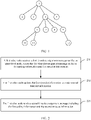
- FIG. 1 is a schematic diagram of a topology of PLC multi-level relaying.
- a node 1 is a CCO
- nodes 4, 6, and 9 are PCOs
- other nodes are STAs.
- FIG. 1 is merely an example. It should be understood that other levels may include one or more PCOs than the first level at which the CCO is located and the last level at which an end node is located. Because each node generally broadcasts a message, only a node whose distance (that is, a length of a circuit connecting various nodes) from each node falls within a specific range can receive a broadcast message. A node that cannot receive the broadcast message can only receive the message forwarded by an upper-level PCO of the node.
- each node may alternatively unicast a message, that is, a target node is indicated in a sent header (Header).
- the two types of messages can be received by a node whose distance from each node falls within a specific range.
- a difference lies in that a node receiving the broadcast message parses a header and a payload (Payload), but a node receiving the unicast message discards the message and does not parse a payload after parsing the header and finding that the message is not sent to the node.
- a message sending mechanism of the CCO, the PCO, and the slave node is time division multiplexing. Timeslots in which the CCO, the PCO, and the slave node can send messages are generally all assigned by the CCO.
- An assigned unit period includes timeslots in which the COO and each PCO send beacon (beacon) packets and timeslots in which all nodes send service data.
- the timeslot in which the PCO sends the beacon (beacon) packet is referred to as a forwarding timeslot for short below
- the timeslot in which each node sends the service data is referred to as a data timeslot for short below.
- the forwarded beacon packet is used to indicate timeslot assignment information.
- the CCO broadcasts a beacon packet to notify another node of a timeslot of the another node. Because the beacon packet broadcast by the CCO cannot directly reach a node far away from the CCO, a PCO that can receive the beacon packet forwards the beacon packet to the node far away from the CCO. The PCO forwards the beacon packet based on a timeslot assigned to the PCO in the received beacon packet. In the conventional technology, in one unit period, all forwarding timeslots are set before all data timeslots, and before forwarding a beacon packet, a PCO basically does not modify other content than some fields such as a destination node identifier.
- all forwarding actions need to be completed, that is, all nodes start to transmit service data only after receiving timeslots indicated by beacon packets. Even if some nodes have received the timeslots indicated by the beacon packets, the nodes can start to send service data only after a last-hop PCO completes forwarding and enters a data timeslot, causing a relatively long delay. Consequently, a large quantity of nodes wait for a long time, and node communication efficiency is very low.
- An embodiment of the present invention provides a timeslot assignment method for power line communication, as shown in FIG. 2 , including:
- Step 201 A first relay node receives a first timeslot assignment message sent by an upper-level node, where the first timeslot assignment message includes forwarding information and first timeslot information; the forwarding information includes a forwarding indication indicating that at least one relay node needs to forward the first timeslot assignment message, and the first timeslot information includes a forwarding timeslot indication assigned to the at least one relay node and used to forward the first timeslot assignment message, and data timeslot indications assigned to a plurality of nodes and used to send service data; and the plurality of nodes include the at least one relay node, and the at least one relay node includes the first relay node.
- the forwarding information includes a forwarding indication indicating that at least one relay node needs to forward the first timeslot assignment message
- the first timeslot information includes a forwarding timeslot indication assigned to the at least one relay node and used to forward the first timeslot assignment message, and data timeslot indications assigned to a plurality of nodes and used to send service data
- the plurality of nodes include
- Step 203 The first relay node updates the first timeslot information to obtain second timeslot information, where the updating includes deleting an expired timeslot indication from the first timeslot information, the expired timeslot indication is a timeslot indication indicating that an indicated timeslot has expired, and the second timeslot information includes a data timeslot indication of at least one node that is used to send service data.
- the first relay node parses the received first timeslot assignment message, identifies a timeslot indicated by each timeslot indication in the first timeslot information, and considers, based on a local clock, a timeslot that is before a current moment of the local clock as an expired timeslot.
- An expired timeslot indicates a time period that has passed, and has no actual meaning.
- Step 205 The first relay node sends a second timeslot assignment message including the forwarding information and the second timeslot information.
- each relay node may delete an expired timeslot before forwarding timeslot indication information. This saves transmission resources, and prevents another node from discarding the received timeslot indication information after discovering, through parsing, that the timeslot indication information expires, to improve processing efficiency.
- the sending manner is broadcasting.
- the first timeslot assignment message and the second timeslot assignment message may be beacon (Beacon) packets defined in the ITU-T G.hn standard or MAP messages defined in the IEEE 1901.1 standard.
- Beacon Beacon
- the updating in step 205 includes deleting a timeslot indication assigned to the first relay node from the first timeslot information, and the timeslot indication assigned to the first relay node includes a forwarding timeslot of the first relay node, or a forwarding timeslot and a data timeslot of the first relay node.
- the first relay node may adjust at least one timeslot indication that is not deleted, and the adjusting includes prolonging or shortening a timeslot.
- each relay node may flexibly adjust, based on a requirement, timeslot indication information sent to a downstream node. This avoids a problem in the conventional technology that a latest timeslot requirement cannot be met because a head node defines that timeslots are all assigned in advance without considering a subsequent transmission parameter change or the like.
- the first relay node may further add timeslot indication information of a new node.
- an upper-level relay node may not need to set timeslot indications of excessive nodes in advance, but indicates only timeslot indications of nodes at the first lower level or the first two lower levels, and timeslot indications of nodes at a lower level may be added layer by layer by upper-level relay nodes of the nodes.
- a timeslot indication can be more flexible, and an actual assignment time point is closer to an assigned timeslot. This can avoid expiration, and can better meet a latest timeslot requirement.
- forwarding information in the second timeslot assignment message includes a forwarding indication indicating that the at least one relay node needs to forward the second timeslot assignment message
- the second timeslot information includes a forwarding timeslot indication assigned to the at least one relay node and used to forward the second timeslot assignment message.
- timeslots separately indicated by a forwarding timeslot indication and a data timeslot indication of at least one PCO that are included in the first timeslot information are adjacent.
- a data timeslot of a same PCO is after a forwarding timeslot of the PCO, and there is no gap between the two timeslots, or there is a gap but the gap is not assigned to another node. In this way, after completing forwarding, the PCO may directly send data without waiting for another node, so that data processing efficiency is improved.
- each of the data timeslots that are assigned to the plurality of nodes for sending the service data may be a data timeslot exclusively occupied by each node, or may be a data timeslot indication that can be shared by all nodes, or some nodes have exclusive timeslots, but some nodes need to preempt shared data timeslots.
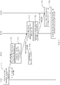
- Step 3011 A node 1 serving as a CCO is marked as CCO1, constructs a first timeslot assignment message, and broadcasts the first timeslot assignment message at a time point T 1T , where the first timeslot assignment message includes forwarding information and first timeslot information, the forwarding information is used to indicate that all PCOs in a network need to forward the first timeslot assignment message, and the first timeslot information is used to indicate a forwarding timeslot assigned to each PCO and a data timeslot assigned to each PCO and each STA.
- the first timeslot assignment message includes forwarding information and first timeslot information
- the forwarding information is used to indicate that all PCOs in a network need to forward the first timeslot assignment message
- the first timeslot information is used to indicate a forwarding timeslot assigned to each PCO and a data timeslot assigned to each PCO and each STA.
- Step 3041 A node 4 serving as the PCO is marked as PCO4, receives the first timeslot assignment message at a time point T 4R , and then updates the first timeslot information in the first timeslot assignment message to obtain second timeslot information, where the updating includes deleting an expired timeslot indication from the first timeslot information, and optionally adjusting an unexpired timeslot indication. Details are described below.
- Step 3042 PCO4 broadcasts a second timeslot assignment message including the forwarding information and the second timeslot information at a time point T 4T in the forwarding timeslot assigned to PCO4.
- Step 3043 If the data timeslot assigned to PCO4 is after the forwarding timeslot of PCO4, the PCO sends service data in the data timeslot of the PCO.
- PCO6 is also a relay node, and processing of PCO6 is similar to that of PCO4.
- Step 3061 PCO6 receives the first timeslot assignment message at a time point T 6R , and then updates the second timeslot information in the second timeslot assignment message to obtain third timeslot information, where the updating includes deleting an expired timeslot indication from the second timeslot information, and optionally adjusting an unexpired timeslot indication.
- Step 3062 PCO6 broadcasts the third timeslot assignment message including the forwarding information and the third timeslot information at a time point T 6T in the forwarding timeslot assigned to PCO6.
- Step 30X1 A node 10 serving as an ordinary station is marked as STA10, and receives the third timeslot assignment message at a moment T 10R .
- Step 30X2 If there is a shared timeslot assigned to all nodes (including an ordinary station and a relay node) after T 10R , STA10 performs timeslot preemption, and if at least a part of the timeslot is preempted, STA10 sends service data in the preempted timeslot. If the preemption fails, STA10 waits for another data timeslot indication. If there is a timeslot assigned exclusively to STA10 after T 10R , STA10 sends service data in the timeslot.
- nodes 2, 3, 5, 7, 8, 11, and 12 are also ordinary stations and can receive the timeslot assignment message broadcast by CCO1, PCO4, or PCO6; and the nodes send service data based on data timeslot indications assigned to the nodes in the message. Processing is similar to that of STA10. FIG. 3 does not show processing steps of the nodes. Certainly, each of data timeslots assigned to the nodes may be a timeslot exclusively occupied by a specific node, or may be a timeslot shared by a plurality of nodes but needs to be preempted.
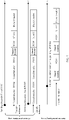
- a first assignment message broadcast by node 1 at a time point T 1T includes a forwarding indication indicating that node 4, node 6, and node 9 need to forward the first timeslot assignment message, and exclusive timeslot information of each of nodes 2 to 12.
- the timeslot information of node 4, node 6, and node 9 includes forwarding timeslot information and data timeslot information, and the timeslot information of nodes 2, 3, 5, 7, 8, 10, 11, and 12 includes only data timeslot information.
- Node 4 receives the first timeslot assignment message at a time point T 4R . Because the time point T 4R is earlier than a timeslot assigned to node 4, node 4 needs to wait for the timeslot of node 4 before forwarding the timeslot assignment message and sending service data. In addition, when reaching a forwarding timeslot of node 4, timeslots assigned to nodes 2 and 3 expire, and node 4 needs to delete the timeslots. Node 4 further deletes a timeslot indication of node 4 to obtain new timeslot information, and then broadcasts the forwarding indication of the first timeslot assignment message and the new timeslot information as a second timeslot assignment message. As shown in FIG.
- the current second timeslot assignment message does not include the forwarding indication of node 4 and the timeslot information of nodes 2 to 4.
- a sending time point T 4T is in the forwarding timeslot of node 4.
- node 4 deletes the first expired timeslot and a timeslot of node 4, and adjusts a subsequent timeslot based on a requirement to obtain new timeslot information.
- timeslots marked as PC04, PC06, PC09, or STA10 are separately timeslots exclusively occupied by nodes 4, 6, 9, and 10, and timeslots marked as shared timeslots are timeslots that can be preempted by all nodes.
- Node 6 receives the second timeslot assignment message at a time point T 6R . Because the time point T 6R is earlier than a timeslot assigned to node 6, node 6 also needs to wait for the timeslot of node 6 before forwarding the timeslot assignment message and sending service data. In addition, when reaching a forwarding timeslot of node 6, the timeslot assigned to node 4 expires, and node 6 needs to delete the timeslot. Node 6 further deletes a timeslot indication of the node 6, and, based on a requirement, prolongs a timeslot of node 10 and shortens a timeslot of node 11 to obtain new timeslot information, and then broadcasts the forwarding indication of the second timeslot assignment message and the new timeslot information as a third timeslot assignment message.
- the current third timeslot assignment message does not include the forwarding indication of node 4 and the timeslot information of nodes 2 and 3.
- a sending time point T 6T is in the forwarding timeslot of node 6.
- Node 6 may determine, based on a condition such as a historical data busy degree or channel quality of another node, whether to adjust a length of a timeslot of the another node. In an optional manner, if there is another node after node 12, node 6 further extends a time axis to indicate another timeslot when obtaining the new timeslot information.
- Node 10 receives the third timeslot assignment message at a time piont T 10R , and sends service data in a data timeslot assigned to node 10 in the third timeslot assignment message.
- a node receives a plurality of timeslot assignment messages at different time points, and forwards the timeslot assignment message or sends service data based on a timeslot indication in the timeslot assignment message as long as receiving the message is received. If a timeslot indicated by a previous received timeslot assignment message has not been reached, a new timeslot assignment message is received, and a timeslot indicated by the new timeslot assignment message is earlier than the timeslot indicated by the previous timeslot assignment message, the node first forwards the timeslot assignment message or sends service data in the timeslot indicated by the new timeslot assignment message. If the timeslot indicated by the subsequently received new timeslot assignment message is later than the timeslot indicated by the previous timeslot assignment message, the node first forwards the timeslot assignment message or sends service data in the timeslot indicated by the previous timeslot assignment message.
- the access point may include a timeslot processing unit 610 and a transceiver unit 620.
- the transceiver unit 620 is configured to receive a first timeslot assignment message sent by an upper-level node, where the first timeslot assignment message includes forwarding information and first timeslot information; the forwarding information includes a forwarding indication indicating that at least one relay node needs to forward the first timeslot assignment message, the first timeslot information includes a forwarding timeslot indication assigned to the at least one relay node and used to forward the first timeslot assignment message, and data timeslot indications assigned to a plurality of nodes and used to send service data; and the plurality of nodes include the at least one relay node, and the at least one relay node includes a first relay node.
- the timeslot processing unit 610 is configured to update the first timeslot information to obtain second timeslot information, where the updating includes deleting an expired timeslot indication from the first timeslot information, the expired timeslot indication is a timeslot indication indicating that an indicated timeslot has expired, and the second timeslot information includes a data timeslot indication of at least one node that is used to send service data.
- the transceiver unit 620 is further configured to send a second timeslot assignment message including the forwarding information and the second timeslot information.
- the sending manner is broadcasting.
- the first timeslot assignment message and the second timeslot assignment message may be beacon packets or MAP messages.
- the updating further includes deleting a timeslot indication assigned to the first relay node from the first timeslot information, and the timeslot indication assigned to the first relay node includes a forwarding timeslot of the first relay node, or a forwarding timeslot and a data timeslot of the first relay node.
- the timeslot processing unit 610 may adjust at least one timeslot indication that is not deleted, and the adjusting includes prolonging or shortening a timeslot.
- Forwarding information in the second timeslot assignment message includes a forwarding indication indicating that the at least one relay node needs to forward the second timeslot assignment message, and the second timeslot information includes a forwarding timeslot indication assigned to the at least one relay node and used to forward the second timeslot assignment message.
- Timeslots separately indicated by a forwarding timeslot indication and a data timeslot indication of at least one PCO that are included in the first timeslot information are adjacent.
- the access point may be any node other than the head node in FIG. 3 .
- a processing manner of the nodes in the embodiment corresponding to FIG. 3 should be jointly completed by the timeslot processing unit 610 and the transceiver unit 620. For details, refer to the content corresponding to FIG. 3 .
- the access point may include a processor 710 and a transceiver 720.
- the processor 710 executes computer instructions, so that the access point performs the method shown in FIG. 2 .
- the optional embodiment corresponding to FIG. 2 is also applicable to the access point in this embodiment. Details are not described again.
- the apparatus further includes a memory 730.
- the memory 730 may be configured to store the foregoing computer instructions and the like.
- An embodiment of this application further provides a power line communications network, including at least one head node.
- Each head node is directly or indirectly connected to at least one relay node, and the relay node is the access point shown in FIG. 6 or FIG. 7 .
- the processor in embodiments of this application may be a central processing unit (central processing unit, CPU), the processor may further be another general-purpose processor, a digital signal processor (digital signal processor, DSP), an application-specific integrated circuit (application specific integrated circuit, ASIC), a field programmable gate array (field programmable gate array, FPGA) or another programmable logic device, a transistor logic device, a hardware component, or any combination thereof.
- the general-purpose processor may be a microprocessor or any conventional processor.
- the method steps in embodiments of this application may be implemented in a hardware manner, or may be implemented in a manner of executing software instructions by the processor.
- the software instructions may include corresponding software modules.
- the software modules may be stored in a random access memory (random access memory, RAM), a flash memory, a read-only memory (read-only memory, ROM), a programmable read-only memory (programmable ROM, PROM), an erasable programmable read-only memory (erasable PROM, EPROM), an electrically erasable programmable read-only memory (electrically EPROM, EEPROM), a register, a hard disk, a removable hard disk, a CD-ROM, or any other form of storage medium well-known in the art.
- a storage medium is coupled to a processor, so that the processor can read information from the storage medium or write information into the storage medium.
- the storage medium may be further a component of the processor.
- the processor and the storage medium may be located in an ASIC.
- All or some of embodiments may be implemented by using software, hardware, firmware, or any combination thereof.
- software is used to implement the embodiments, all or a part of the embodiments may be implemented in a form of a computer program product.
- the computer program product includes one or more computer instructions.
- the computer may be a general-purpose computer, a dedicated computer, a computer network, or another programmable apparatus.
- the computer instructions may be stored in a computer-readable storage medium or may be transmitted by using the computer-readable storage medium.
- the computer instructions may be transmitted from a website, computer, server, or data center to another website, computer, server, or data center in a wired (for example, a coaxial cable, an optical fiber, or a digital subscriber line (DSL)) or wireless (for example, infrared, radio, or microwave) manner.
- the computer-readable storage medium may be any usable medium accessible by a computer, or a data storage device, such as a server or a data center, integrating one or more usable media.
- the usable medium may be a magnetic medium (for example, a floppy disk, a hard disk, or a magnetic tape), an optical medium (for example, a DVD), a semiconductor medium (for example, a solid-state drive (solid state disk, SSD)), or the like.
Abstract
Description
- This application claims priority to
Chinese Patent Application No. 202010076048.6, filed on January 23, 2020 - This application relates to the field of power line communication, and in particular, to a timeslot assignment method for power line communication and an apparatus.
- In an application scenario of power line communication (power line communication, PLC), there is a requirement for long-distance and multi-level relaying. For example, light control is performed through PLC in airfield ground lighting. A maximum of a power line on a runway reaches several kilometers, and a maximum of a single-hop communication distance in PLC is about 1.2 km. Therefore, remote light control can be implemented only through multi-level relaying. For example, street lamps are controlled through PLC. Because the street lights extend over a very long distance, control information needs to be forwarded by relay nodes, to implement unified control of the street lamps.
- Based on the feature of the multi-level relaying, a message such as a control message sent by a head node needs to be forwarded by a plurality of relay nodes before reaching an end node. In this case, a delay of receiving the message by the end node is relatively long. In an existing solution, sufficient time is reserved for each relay node to forward the message, and consequently efficiency of this message forwarding mode is definitely low.
- Embodiments of this application provide a timeslot assignment method for power line communication, an apparatus, and a system. Forwarding efficiency of a relay node can be greatly improved.
- According to a first aspect, an embodiment of this application provides a timeslot assignment method for power line communication, applied to a multi-level power line communications network, where the multi-level power line communications network includes at least one head node, each head node is directly or indirectly connected to at least one relay node, cascading of a plurality of relay nodes may be considered as a plurality of levels, one of the at least one relay node (which may be referred to as a first relay node) is used as a representative for description, and the method includes:
- The first relay node receives a first timeslot assignment message sent by an upper-level node, where the first timeslot assignment message includes forwarding information and first timeslot information; and the forwarding information includes a forwarding indication indicating that the at least one relay node needs to forward the first timeslot assignment message, and the first timeslot information includes a forwarding timeslot indication assigned to the at least one relay node and used to forward the first timeslot assignment message, and data timeslot indications assigned to a plurality of nodes and used to send service data.
- The first relay node updates the first timeslot information to obtain second timeslot information, where the updating includes deleting an expired timeslot indication from the first timeslot information, the expired timeslot indication is a timeslot indication indicating that an indicated timeslot has expired, and the second timeslot information includes a data timeslot indication of at least one node that is used to send service data.
- The first relay node sends a second timeslot assignment message including the forwarding information and the second timeslot information.
- By using the solution in this embodiment, each relay node may delete an expired timeslot before forwarding timeslot indication information. This saves transmission resources, and prevents another node from discarding the received timeslot indication information after discovering, through parsing, that the timeslot indication information expires, to improve processing efficiency.
- In a possible implementation, the updating further includes deleting a timeslot indication assigned to the first relay node from the first timeslot information, and the timeslot indication assigned to the first relay node includes a forwarding timeslot of the first relay node, or a forwarding timeslot and a data timeslot of the first relay node.
- In a possible implementation, the updating further includes adjusting at least one timeslot indication that is not deleted, and the adjusting includes prolonging or shortening a timeslot.
- In a possible implementation, forwarding information in the second timeslot assignment message includes a forwarding indication indicating that the at least one relay node needs to forward the second timeslot assignment message, and the second timeslot information includes a forwarding timeslot indication assigned to the at least one relay node and used to forward the second timeslot assignment message.
- By using the solution of this embodiment, each relay node may flexibly adjust, based on a requirement, timeslot indication information sent to a downstream node. This avoids a problem in the conventional technology that a latest requirement cannot be met because a head node defines that timeslots are all assigned in advance without considering a subsequent transmission parameter change or the like.
- In a possible implementation, timeslots separately indicated by a forwarding timeslot indication and a data timeslot indication of at least one relay node that are included in the first timeslot information are adjacent.
- In a possible implementation, the first relay node may further add timeslot indication information of a new node. In this manner, an upper-level relay node may not need to set timeslot indications of excessive nodes in advance, but indicates only timeslot indications of nodes at the first lower level or the first two lower levels, and timeslot indications of nodes at a lower level may be added layer by layer by upper-level relay nodes of the nodes. In this way, a timeslot indication can be more flexible, and an actual assignment time point is closer to an assigned timeslot. This can avoid expiration, and can better meet a latest timeslot requirement.
- According to a second aspect, an embodiment of this application provides an access point, including a slot processing unit and a transceiver unit.
- The transceiver unit receives a first timeslot assignment message sent by an upper-level node, where the first timeslot assignment message includes forwarding information and first timeslot information; the forwarding information includes a forwarding indication indicating that at least one relay node needs to forward the first timeslot assignment message, and the first timeslot information includes a forwarding timeslot indication assigned to the at least one relay node and used to forward the first timeslot assignment message, and data timeslot indications assigned to a plurality of nodes and used to send service data; and the plurality of nodes include the at least one relay node, and the at least one relay node includes a first relay node.
- The timeslot processing unit is configured to update the first timeslot information to obtain second timeslot information, where the updating includes deleting an expired timeslot indication from the first timeslot information, the expired timeslot indication is a timeslot indication indicating that an indicated timeslot has expired, and the second timeslot information includes a data timeslot indication of at least one node that is used to send service data.
- The transceiver unit is further configured to send a second timeslot assignment message including the forwarding information and the second timeslot information.
- In a possible implementation, the updating includes deleting a timeslot indication assigned to the first relay node from the first timeslot information, and the timeslot indication assigned to the first relay node includes a forwarding timeslot of the first relay node, or a forwarding timeslot and a data timeslot of the first relay node.
- In a possible implementation, the updating includes adjusting at least one timeslot indication that is not deleted, and the adjusting includes prolonging or shortening a timeslot.
- In a possible implementation, forwarding information in the second timeslot assignment message includes a forwarding indication indicating that the at least one relay node needs to forward the second timeslot assignment message, and the second timeslot information includes a forwarding timeslot indication assigned to the at least one relay node and used to forward the second timeslot assignment message.
- In a possible implementation, timeslots separately indicated by a forwarding timeslot indication and a data timeslot indication of at least one relay node that are included in the first timeslot information are adjacent.
- According to a third aspect, an embodiment of this application provides an access point, including a processor and a transceiver. When the access point is run, the processor executes computer instructions, so that the access point performs the method according to the first aspect.
- In a possible implementation, the apparatus further includes a memory. The memory is configured to store the foregoing computer instructions.
- According to a fourth aspect, an embodiment of this application provides a power line communications network, including at least one head node, where each head node is at least directly or indirectly connected to one or more relay nodes, and the relay node is the foregoing access point.
-
-
FIG. 1 is a schematic diagram of a topology of PLC multi-level relaying; -
FIG. 2 is a flowchart of a timeslot assignment method for power line communication according to an embodiment of the present invention; -
FIG. 3 is another flowchart of a timeslot assignment method for power line communication according to an embodiment of the present invention; -
FIG. 4 is a schematic diagram of timeslot assignment according to an embodiment of the present invention; -
FIG. 5 is another schematic diagram of timeslot assignment according to an embodiment of the present invention; -
FIG. 6 is a schematic diagram of a structure of another access point according to an embodiment of this application; and -
FIG. 7 is a schematic diagram of a structure of another access point according to an embodiment of this application. - In this specification, the claims, and the accompanying drawings of this application, terms "first", "second", "third", "fourth", and the like (if existent) are intended to distinguish between similar objects but do not necessarily indicate a specific order or sequence. It should be understood that the data termed in such a way are interchangeable in proper circumstances so that embodiments of this application described herein can be implemented in orders except the order illustrated or described herein. Moreover, terms "include", "contain" and any other variants thereof mean to cover the non-exclusive inclusion. For example, a process, a method, a system, a product, or a device that includes a list of steps or units is not necessarily limited to those expressly listed steps or units, but may include other steps or units not expressly listed or inherent to such the process, the method, the product, or the device.
- A PLC network, also referred to as a carrier communications network, is a communications network that uses low-voltage power lines as communications media to aggregate, transmit, and exchange power consumption information of low-voltage electric power users, and mainly adopts an orthogonal frequency division multiplexing technology. PLC with 1 MHz or below 1 MHz is generally referred to as narrowband PLC, PLC with a band ranging from 2 MHz to 12 MHz is referred to as mid-band PLC, and PLC with a band ranging from 2 MHz to 80 MHz is referred to as broadband PLC. As shown in
FIG. 1 , a PLC network generally includes a head node, a relay node, and a slave node. The head node is a central coordinator (central coordinator, CCO), and serves as a master node in the network to be responsible for completing functions such as networking control and network maintenance and management. A device entity corresponding to the head node is a concentrator local communications unit. The relay node is a proxy coordinator (proxy coordinator, PCO), is a station configured to perform data relaying and forwarding between the central coordinator and a station or between stations, and is also referred to as a proxy node. The slave node is a common station (station, STA), and serves as a slave node in the communications network. A device entity corresponding to the slave node is a communications unit, and includes an electricity meter carrier module, an I-type collector carrier module, an II-type collector, or the like. In this specification, the head node, the master node, and the central coordinator are a same concept, and for ease of description, are referred to as a CCO for short below. The relay node, the proxy node, and the proxy coordinator are a same concept, and for ease of description, are referred to as a PCO for short below. -
FIG. 1 is a schematic diagram of a topology of PLC multi-level relaying. In the figure, anode 1 is a CCO,nodes FIG. 1 is merely an example. It should be understood that other levels may include one or more PCOs than the first level at which the CCO is located and the last level at which an end node is located. Because each node generally broadcasts a message, only a node whose distance (that is, a length of a circuit connecting various nodes) from each node falls within a specific range can receive a broadcast message. A node that cannot receive the broadcast message can only receive the message forwarded by an upper-level PCO of the node. Certainly, each node may alternatively unicast a message, that is, a target node is indicated in a sent header (Header). The two types of messages can be received by a node whose distance from each node falls within a specific range. A difference lies in that a node receiving the broadcast message parses a header and a payload (Payload), but a node receiving the unicast message discards the message and does not parse a payload after parsing the header and finding that the message is not sent to the node. - A message sending mechanism of the CCO, the PCO, and the slave node is time division multiplexing. Timeslots in which the CCO, the PCO, and the slave node can send messages are generally all assigned by the CCO. An assigned unit period includes timeslots in which the COO and each PCO send beacon (beacon) packets and timeslots in which all nodes send service data. For ease of description, the timeslot in which the PCO sends the beacon (beacon) packet is referred to as a forwarding timeslot for short below, and the timeslot in which each node sends the service data is referred to as a data timeslot for short below. The forwarded beacon packet is used to indicate timeslot assignment information. Generally, the CCO broadcasts a beacon packet to notify another node of a timeslot of the another node. Because the beacon packet broadcast by the CCO cannot directly reach a node far away from the CCO, a PCO that can receive the beacon packet forwards the beacon packet to the node far away from the CCO. The PCO forwards the beacon packet based on a timeslot assigned to the PCO in the received beacon packet. In the conventional technology, in one unit period, all forwarding timeslots are set before all data timeslots, and before forwarding a beacon packet, a PCO basically does not modify other content than some fields such as a destination node identifier. In this way, all forwarding actions need to be completed, that is, all nodes start to transmit service data only after receiving timeslots indicated by beacon packets. Even if some nodes have received the timeslots indicated by the beacon packets, the nodes can start to send service data only after a last-hop PCO completes forwarding and enters a data timeslot, causing a relatively long delay. Consequently, a large quantity of nodes wait for a long time, and node communication efficiency is very low.
- An embodiment of the present invention provides a timeslot assignment method for power line communication, as shown in
FIG. 2 , including: - Step 201: A first relay node receives a first timeslot assignment message sent by an upper-level node, where the first timeslot assignment message includes forwarding information and first timeslot information; the forwarding information includes a forwarding indication indicating that at least one relay node needs to forward the first timeslot assignment message, and the first timeslot information includes a forwarding timeslot indication assigned to the at least one relay node and used to forward the first timeslot assignment message, and data timeslot indications assigned to a plurality of nodes and used to send service data; and the plurality of nodes include the at least one relay node, and the at least one relay node includes the first relay node.
- Step 203: The first relay node updates the first timeslot information to obtain second timeslot information, where the updating includes deleting an expired timeslot indication from the first timeslot information, the expired timeslot indication is a timeslot indication indicating that an indicated timeslot has expired, and the second timeslot information includes a data timeslot indication of at least one node that is used to send service data.
- Specifically, the first relay node parses the received first timeslot assignment message, identifies a timeslot indicated by each timeslot indication in the first timeslot information, and considers, based on a local clock, a timeslot that is before a current moment of the local clock as an expired timeslot. An expired timeslot indicates a time period that has passed, and has no actual meaning.
- Step 205: The first relay node sends a second timeslot assignment message including the forwarding information and the second timeslot information.
- By using the solution in this embodiment, each relay node may delete an expired timeslot before forwarding timeslot indication information. This saves transmission resources, and prevents another node from discarding the received timeslot indication information after discovering, through parsing, that the timeslot indication information expires, to improve processing efficiency.
- The sending manner is broadcasting. The first timeslot assignment message and the second timeslot assignment message may be beacon (Beacon) packets defined in the ITU-T G.hn standard or MAP messages defined in the IEEE 1901.1 standard.
- In an optional embodiment, the updating in
step 205 includes deleting a timeslot indication assigned to the first relay node from the first timeslot information, and the timeslot indication assigned to the first relay node includes a forwarding timeslot of the first relay node, or a forwarding timeslot and a data timeslot of the first relay node. - In another optional embodiment, the first relay node may adjust at least one timeslot indication that is not deleted, and the adjusting includes prolonging or shortening a timeslot.
- By using the solution of this embodiment, each relay node may flexibly adjust, based on a requirement, timeslot indication information sent to a downstream node. This avoids a problem in the conventional technology that a latest timeslot requirement cannot be met because a head node defines that timeslots are all assigned in advance without considering a subsequent transmission parameter change or the like.
- In still another optional embodiment, the first relay node may further add timeslot indication information of a new node. In this manner, an upper-level relay node may not need to set timeslot indications of excessive nodes in advance, but indicates only timeslot indications of nodes at the first lower level or the first two lower levels, and timeslot indications of nodes at a lower level may be added layer by layer by upper-level relay nodes of the nodes. In this way, a timeslot indication can be more flexible, and an actual assignment time point is closer to an assigned timeslot. This can avoid expiration, and can better meet a latest timeslot requirement.
- In still another optional embodiment, forwarding information in the second timeslot assignment message includes a forwarding indication indicating that the at least one relay node needs to forward the second timeslot assignment message, and the second timeslot information includes a forwarding timeslot indication assigned to the at least one relay node and used to forward the second timeslot assignment message.
- In still another optional embodiment, timeslots separately indicated by a forwarding timeslot indication and a data timeslot indication of at least one PCO that are included in the first timeslot information are adjacent. To be specific, a data timeslot of a same PCO is after a forwarding timeslot of the PCO, and there is no gap between the two timeslots, or there is a gap but the gap is not assigned to another node. In this way, after completing forwarding, the PCO may directly send data without waiting for another node, so that data processing efficiency is improved.
- As an optional feature, each of the data timeslots that are assigned to the plurality of nodes for sending the service data may be a data timeslot exclusively occupied by each node, or may be a data timeslot indication that can be shared by all nodes, or some nodes have exclusive timeslots, but some nodes need to preempt shared data timeslots.
- The following provides detailed description with reference to the network shown in
FIG. 1 . Refer toFIG. 3 . - Step 3011: A
node 1 serving as a CCO is marked as CCO1, constructs a first timeslot assignment message, and broadcasts the first timeslot assignment message at a time point T1T, where the first timeslot assignment message includes forwarding information and first timeslot information, the forwarding information is used to indicate that all PCOs in a network need to forward the first timeslot assignment message, and the first timeslot information is used to indicate a forwarding timeslot assigned to each PCO and a data timeslot assigned to each PCO and each STA. - Step 3041: A
node 4 serving as the PCO is marked as PCO4, receives the first timeslot assignment message at a time point T4R, and then updates the first timeslot information in the first timeslot assignment message to obtain second timeslot information, where the updating includes deleting an expired timeslot indication from the first timeslot information, and optionally adjusting an unexpired timeslot indication. Details are described below. - Step 3042: PCO4 broadcasts a second timeslot assignment message including the forwarding information and the second timeslot information at a time point T4T in the forwarding timeslot assigned to PCO4.
- Step 3043: If the data timeslot assigned to PCO4 is after the forwarding timeslot of PCO4, the PCO sends service data in the data timeslot of the PCO.
- PCO6 is also a relay node, and processing of PCO6 is similar to that of PCO4.
- Step 3061: PCO6 receives the first timeslot assignment message at a time point T6R, and then updates the second timeslot information in the second timeslot assignment message to obtain third timeslot information, where the updating includes deleting an expired timeslot indication from the second timeslot information, and optionally adjusting an unexpired timeslot indication.
- Step 3062: PCO6 broadcasts the third timeslot assignment message including the forwarding information and the third timeslot information at a time point T6T in the forwarding timeslot assigned to PCO6.
- Step 30X1: A
node 10 serving as an ordinary station is marked as STA10, and receives the third timeslot assignment message at a moment T10R. - Step 30X2: If there is a shared timeslot assigned to all nodes (including an ordinary station and a relay node) after T10R, STA10 performs timeslot preemption, and if at least a part of the timeslot is preempted, STA10 sends service data in the preempted timeslot. If the preemption fails, STA10 waits for another data timeslot indication. If there is a timeslot assigned exclusively to STA10 after T10R, STA10 sends service data in the timeslot.
- It should be noted that,
nodes FIG. 3 does not show processing steps of the nodes. Certainly, each of data timeslots assigned to the nodes may be a timeslot exclusively occupied by a specific node, or may be a timeslot shared by a plurality of nodes but needs to be preempted. - The following describes timeslot indication adjustment in
FIG. 3 with reference toFIG. 4 . As shown inFIG. 4 , a first assignment message broadcast bynode 1 at a time point T1T includes a forwarding indication indicating thatnode 4,node 6, andnode 9 need to forward the first timeslot assignment message, and exclusive timeslot information of each ofnodes 2 to 12. The timeslot information ofnode 4,node 6, andnode 9 includes forwarding timeslot information and data timeslot information, and the timeslot information ofnodes -
Node 4 receives the first timeslot assignment message at a time point T4R. Because the time point T4R is earlier than a timeslot assigned tonode 4,node 4 needs to wait for the timeslot ofnode 4 before forwarding the timeslot assignment message and sending service data. In addition, when reaching a forwarding timeslot ofnode 4, timeslots assigned tonodes node 4 needs to delete the timeslots.Node 4 further deletes a timeslot indication ofnode 4 to obtain new timeslot information, and then broadcasts the forwarding indication of the first timeslot assignment message and the new timeslot information as a second timeslot assignment message. As shown inFIG. 4 , compared with the first timeslot assignment message, the current second timeslot assignment message does not include the forwarding indication ofnode 4 and the timeslot information ofnodes 2 to 4. A sending time point T4T is in the forwarding timeslot ofnode 4. Although in this scenario, each node has an exclusive timeslot, it may be understood that an expired shared timeslot is processed in a similar manner. As shown inFIG. 5 ,node 4 deletes the first expired timeslot and a timeslot ofnode 4, and adjusts a subsequent timeslot based on a requirement to obtain new timeslot information. InFIG. 5 , timeslots marked as PC04, PC06, PC09, or STA10 are separately timeslots exclusively occupied bynodes -
Node 6 receives the second timeslot assignment message at a time point T6R. Because the time point T6R is earlier than a timeslot assigned tonode 6,node 6 also needs to wait for the timeslot ofnode 6 before forwarding the timeslot assignment message and sending service data. In addition, when reaching a forwarding timeslot ofnode 6, the timeslot assigned tonode 4 expires, andnode 6 needs to delete the timeslot.Node 6 further deletes a timeslot indication of thenode 6, and, based on a requirement, prolongs a timeslot ofnode 10 and shortens a timeslot ofnode 11 to obtain new timeslot information, and then broadcasts the forwarding indication of the second timeslot assignment message and the new timeslot information as a third timeslot assignment message. As shown inFIG. 4 , compared with the second timeslot assignment message, the current third timeslot assignment message does not include the forwarding indication ofnode 4 and the timeslot information ofnodes node 6.Node 6 may determine, based on a condition such as a historical data busy degree or channel quality of another node, whether to adjust a length of a timeslot of the another node. In an optional manner, if there is another node afternode 12,node 6 further extends a time axis to indicate another timeslot when obtaining the new timeslot information. -
Node 10 receives the third timeslot assignment message at a time piont T10R, and sends service data in a data timeslot assigned tonode 10 in the third timeslot assignment message. - In a PLC network, a node receives a plurality of timeslot assignment messages at different time points, and forwards the timeslot assignment message or sends service data based on a timeslot indication in the timeslot assignment message as long as receiving the message is received. If a timeslot indicated by a previous received timeslot assignment message has not been reached, a new timeslot assignment message is received, and a timeslot indicated by the new timeslot assignment message is earlier than the timeslot indicated by the previous timeslot assignment message, the node first forwards the timeslot assignment message or sends service data in the timeslot indicated by the new timeslot assignment message. If the timeslot indicated by the subsequently received new timeslot assignment message is later than the timeslot indicated by the previous timeslot assignment message, the node first forwards the timeslot assignment message or sends service data in the timeslot indicated by the previous timeslot assignment message.
- Refer to
FIG. 6 . An embodiment of this application provides an access point. The access point may include a timeslot processing unit 610 and a transceiver unit 620. - The transceiver unit 620 is configured to receive a first timeslot assignment message sent by an upper-level node, where the first timeslot assignment message includes forwarding information and first timeslot information; the forwarding information includes a forwarding indication indicating that at least one relay node needs to forward the first timeslot assignment message, the first timeslot information includes a forwarding timeslot indication assigned to the at least one relay node and used to forward the first timeslot assignment message, and data timeslot indications assigned to a plurality of nodes and used to send service data; and the plurality of nodes include the at least one relay node, and the at least one relay node includes a first relay node.
- The timeslot processing unit 610 is configured to update the first timeslot information to obtain second timeslot information, where the updating includes deleting an expired timeslot indication from the first timeslot information, the expired timeslot indication is a timeslot indication indicating that an indicated timeslot has expired, and the second timeslot information includes a data timeslot indication of at least one node that is used to send service data.
- The transceiver unit 620 is further configured to send a second timeslot assignment message including the forwarding information and the second timeslot information.
- The sending manner is broadcasting. The first timeslot assignment message and the second timeslot assignment message may be beacon packets or MAP messages.
- The updating further includes deleting a timeslot indication assigned to the first relay node from the first timeslot information, and the timeslot indication assigned to the first relay node includes a forwarding timeslot of the first relay node, or a forwarding timeslot and a data timeslot of the first relay node.
- The timeslot processing unit 610 may adjust at least one timeslot indication that is not deleted, and the adjusting includes prolonging or shortening a timeslot.
- Forwarding information in the second timeslot assignment message includes a forwarding indication indicating that the at least one relay node needs to forward the second timeslot assignment message, and the second timeslot information includes a forwarding timeslot indication assigned to the at least one relay node and used to forward the second timeslot assignment message.
- Timeslots separately indicated by a forwarding timeslot indication and a data timeslot indication of at least one PCO that are included in the first timeslot information are adjacent.
- The access point may be any node other than the head node in
FIG. 3 . A processing manner of the nodes in the embodiment corresponding toFIG. 3 should be jointly completed by the timeslot processing unit 610 and the transceiver unit 620. For details, refer to the content corresponding toFIG. 3 . - Refer to
FIG. 7 . An embodiment of this application provides an access point. The access point may include a processor 710 and a transceiver 720. When the access point is run, the processor 710 executes computer instructions, so that the access point performs the method shown inFIG. 2 . The optional embodiment corresponding toFIG. 2 is also applicable to the access point in this embodiment. Details are not described again. - In some embodiments, as shown in
FIG. 7 , the apparatus further includes a memory 730. The memory 730 may be configured to store the foregoing computer instructions and the like. - An embodiment of this application further provides a power line communications network, including at least one head node. Each head node is directly or indirectly connected to at least one relay node, and the relay node is the access point shown in
FIG. 6 or FIG. 7 . - It may be understood that, the processor in embodiments of this application may be a central processing unit (central processing unit, CPU), the processor may further be another general-purpose processor, a digital signal processor (digital signal processor, DSP), an application-specific integrated circuit (application specific integrated circuit, ASIC), a field programmable gate array (field programmable gate array, FPGA) or another programmable logic device, a transistor logic device, a hardware component, or any combination thereof. The general-purpose processor may be a microprocessor or any conventional processor.
- The method steps in embodiments of this application may be implemented in a hardware manner, or may be implemented in a manner of executing software instructions by the processor. The software instructions may include corresponding software modules. The software modules may be stored in a random access memory (random access memory, RAM), a flash memory, a read-only memory (read-only memory, ROM), a programmable read-only memory (programmable ROM, PROM), an erasable programmable read-only memory (erasable PROM, EPROM), an electrically erasable programmable read-only memory (electrically EPROM, EEPROM), a register, a hard disk, a removable hard disk, a CD-ROM, or any other form of storage medium well-known in the art. For example, a storage medium is coupled to a processor, so that the processor can read information from the storage medium or write information into the storage medium. Certainly, the storage medium may be further a component of the processor. The processor and the storage medium may be located in an ASIC.
- All or some of embodiments may be implemented by using software, hardware, firmware, or any combination thereof. When software is used to implement the embodiments, all or a part of the embodiments may be implemented in a form of a computer program product. The computer program product includes one or more computer instructions. When the computer program instructions are loaded and executed on the computer, the procedure or functions according to embodiments of this application are all or partially generated. The computer may be a general-purpose computer, a dedicated computer, a computer network, or another programmable apparatus. The computer instructions may be stored in a computer-readable storage medium or may be transmitted by using the computer-readable storage medium. The computer instructions may be transmitted from a website, computer, server, or data center to another website, computer, server, or data center in a wired (for example, a coaxial cable, an optical fiber, or a digital subscriber line (DSL)) or wireless (for example, infrared, radio, or microwave) manner. The computer-readable storage medium may be any usable medium accessible by a computer, or a data storage device, such as a server or a data center, integrating one or more usable media. The usable medium may be a magnetic medium (for example, a floppy disk, a hard disk, or a magnetic tape), an optical medium (for example, a DVD), a semiconductor medium (for example, a solid-state drive (solid state disk, SSD)), or the like.
- Finally, it should be noted that the foregoing descriptions are merely specific implementations of this application, but are not intended to limit the protection scope of this application. Any variation or replacement readily figured out by a person skilled in the art within the technical scope disclosed in this application shall fall within the protection scope of this application. Therefore, the protection scope of this application shall be subject to the protection scope of the claims.
Claims (13)
- A timeslot assignment method for power line communication, comprising:receiving, by a first relay node, a first timeslot assignment message sent by an upper-level node, wherein the first timeslot assignment message comprises forwarding information and first timeslot information; the forwarding information comprises a forwarding indication indicating that at least one relay node needs to forward the first timeslot assignment message, and the first timeslot information comprises a forwarding timeslot indication assigned to the at least one relay node and used to forward the first timeslot assignment message, and data timeslot indications assigned to a plurality of nodes and used to send service data; and the plurality of nodes comprise the at least one relay node, and the at least one relay node comprises the first relay node;updating, by the first relay node, the first timeslot information to obtain second timeslot information, wherein the updating comprises deleting an expired timeslot indication from the first timeslot information, the expired timeslot indication is a timeslot indication indicating that an indicated timeslot has expired, and the second timeslot information comprises a data timeslot indication of at least one node that is used to send service data; andsending, by the first relay node, a second timeslot assignment message comprising the forwarding information and the second timeslot information.
- The method according to claim 1, wherein the updating comprises deleting a timeslot indication assigned to the first relay node from the first timeslot information, and the timeslot indication assigned to the first relay node comprises a forwarding timeslot of the first relay node, or a forwarding timeslot and a data timeslot of the first relay node.
- The method according to claim 1, wherein the updating further comprises adjusting at least one timeslot indication that is not deleted, and the adjusting comprises prolonging or shortening a timeslot.
- The method according to any one of claims 1 to 3, wherein forwarding information in the second timeslot assignment message comprises a forwarding indication indicating that the at least one relay node needs to forward the second timeslot assignment message, and the second timeslot information comprises a forwarding timeslot indication assigned to the at least one relay node and used to forward the second timeslot assignment message.
- The method according to any one of claims 1 to 3, wherein timeslots separately indicated by a forwarding timeslot indication and a data timeslot indication of at least one relay node that are comprised in the first timeslot information are adjacent.
- The method according to any one of claims 1 to 3, wherein the first timeslot assignment message and the second timeslot assignment message may be beacon (Beacon) packets defined in the ITU-T G.hn standard or MAP messages defined in the IEEE 1901.1 standard.
- An access point, comprising a timeslot processing unit 610 and a transceiver unit 620, whereinthe transceiver unit 620 is configured to receive a first timeslot assignment message sent by an upper-level node, wherein the first timeslot assignment message comprises forwarding information and first timeslot information; the forwarding information comprises a forwarding indication indicating that at least one relay node needs to forward the first timeslot assignment message, and the first timeslot information comprises a forwarding timeslot indication assigned to the at least one relay node and used to forward the first timeslot assignment message, and data timeslot indications assigned to a plurality of nodes and used to send service data; and the plurality of nodes comprise the at least one relay node, and the at least one relay node comprises a first relay node;the timeslot processing unit 610 is configured to update the first timeslot information to obtain second timeslot information, wherein the updating comprises deleting an expired timeslot indication from the first timeslot information, the expired timeslot indication is a timeslot indication indicating that an indicated timeslot has expired, and the second timeslot information comprises a data timeslot indication of at least one node that is used to send service data; andthe transceiver unit 620 is configured to send a second timeslot assignment message comprising the forwarding information and the second timeslot information.
- The access point according to claim 7, wherein the updating comprises deleting a timeslot indication assigned to the first relay node from the first timeslot information, and the timeslot indication assigned to the first relay node comprises a forwarding timeslot of the first relay node, or a forwarding timeslot and a data timeslot of the first relay node.
- The access point according to claim 7, wherein the updating comprises adjusting at least one timeslot indication that is not deleted, and the adjusting comprises prolonging or shortening a timeslot.
- The access point according to any one of claims 7 to 9, wherein forwarding information in the second timeslot assignment message comprises a forwarding indication indicating that the at least one relay node needs to forward the second timeslot assignment message, and the second timeslot information comprises a forwarding timeslot indication assigned to the at least one relay node and used to forward the second timeslot assignment message.
- The access point according to any one of claims 7 to 9, wherein timeslots separately indicated by a forwarding timeslot indication and a data timeslot indication of at least one relay node that are comprised in the first timeslot information are adjacent.
- The access point according to any one of claims 7 to 9, wherein the first relay node adds timeslot indication information of a new node.
- A power line communications network, comprising at least one head node, wherein each head node is at least directly or indirectly connected to one or more relay nodes, and the relay node is the access point according to any one of claims 7 to 12.
Applications Claiming Priority (2)
| Application Number | Priority Date | Filing Date | Title |
|---|---|---|---|
| CN202010076048.6A CN113162655A (en) | 2020-01-23 | 2020-01-23 | Power line communication time slot distribution method and device |
| PCT/CN2021/072710 WO2021147860A1 (en) | 2020-01-23 | 2021-01-19 | Time slot allocation method and apparatus for power line communication |
Publications (2)
| Publication Number | Publication Date |
|---|---|
| EP4084348A1 true EP4084348A1 (en) | 2022-11-02 |
| EP4084348A4 EP4084348A4 (en) | 2023-06-14 |
Family
ID=76881834
Family Applications (1)
| Application Number | Title | Priority Date | Filing Date |
|---|---|---|---|
| EP21743724.3A Pending EP4084348A4 (en) | 2020-01-23 | 2021-01-19 | Time slot allocation method and apparatus for power line communication |
Country Status (4)
| Country | Link |
|---|---|
| US (1) | US20220360351A1 (en) |
| EP (1) | EP4084348A4 (en) |
| CN (1) | CN113162655A (en) |
| WO (1) | WO2021147860A1 (en) |
Families Citing this family (3)
| Publication number | Priority date | Publication date | Assignee | Title |
|---|---|---|---|---|
| CN113596952A (en) * | 2021-07-26 | 2021-11-02 | 中国电子科技集团公司第五十四研究所 | Autonomous selection dynamic route relay method and system |
| CN114375057B (en) * | 2022-03-22 | 2022-07-22 | 杭州格物智安科技有限公司 | Wireless network system node time slot allocation method |
| WO2023236145A1 (en) * | 2022-06-09 | 2023-12-14 | 华为技术有限公司 | Communication method and apparatus |
Family Cites Families (17)
| Publication number | Priority date | Publication date | Assignee | Title |
|---|---|---|---|---|
| WO2007053954A1 (en) * | 2005-11-10 | 2007-05-18 | Nortel Networks Limited | Zones for wireless networks with relays |
| KR20070073138A (en) * | 2006-01-03 | 2007-07-10 | 삼성전자주식회사 | Apparatus and method for transparent relay in multi-hop relay broadband wireless access communication systems |
| EP1830490B1 (en) * | 2006-03-03 | 2013-07-03 | Samsung Electronics Co., Ltd. | Apparatus and method for supporting relay service in a multi-hop relay broadband wireless access communication system |
| US7929546B2 (en) * | 2006-05-25 | 2011-04-19 | Motorola Solutions, Inc. | Systems, methods and apparatus for allocating time slots in an ad hoc wireless communication network |
| WO2008050425A1 (en) * | 2006-10-25 | 2008-05-02 | Fujitsu Limited | Radio base station, relay station, radio communication system, and radio communication method |
| US9413686B2 (en) * | 2007-06-04 | 2016-08-09 | Qualcomm Incorporated | Establishing a unique end-to-end management key |
| KR20100117951A (en) * | 2009-04-27 | 2010-11-04 | 삼성전자주식회사 | Communication method and apparatus in mobile ad-hoc network |
| CN101895931B (en) * | 2009-05-20 | 2013-01-02 | 中国科学院沈阳自动化研究所 | Searching and balance idea based industrial wireless network communication resource distributing method |
| WO2010150952A1 (en) * | 2009-06-23 | 2010-12-29 | Lg Electronics Inc. | Method for transmitting scheduling information in mobile communication system and femtocell base station apparatus using the same |
| US8190564B2 (en) * | 2010-02-25 | 2012-05-29 | Ebay, Inc. | Temporary session data storage |
| US20130094459A1 (en) * | 2011-10-14 | 2013-04-18 | Texas Instruments Incorporated | Beacon Slot Allocation in Prime |
| US9801114B2 (en) * | 2011-11-11 | 2017-10-24 | Stmicroelectronics, Inc. | System and method for an energy efficient network adaptor with security provisions |
| CN103560840B (en) * | 2013-10-28 | 2015-11-25 | 华为技术有限公司 | A kind of method, apparatus and system of SOT state of termination monitoring |
| US9420583B2 (en) * | 2014-07-07 | 2016-08-16 | The Boeing Company | Combined voice and data communications in a distributed hybrid allocation and reservation multiple access mobile wireless network |
| CN110035509B (en) * | 2018-01-12 | 2023-01-17 | 中国信息通信研究院 | Mobile communication uplink multi-slot scheduling method and system |
| CN110149711B (en) * | 2018-02-13 | 2022-09-16 | 成都华为技术有限公司 | Signal transmission method and device |
| CN109548084B (en) * | 2019-01-17 | 2021-11-30 | 重庆邮电大学 | Load-balanced efficient multi-hop TDMA (time division multiple Access) access method for ad hoc network of unmanned aerial vehicle |
-
2020
- 2020-01-23 CN CN202010076048.6A patent/CN113162655A/en active Pending
-
2021
- 2021-01-19 WO PCT/CN2021/072710 patent/WO2021147860A1/en unknown
- 2021-01-19 EP EP21743724.3A patent/EP4084348A4/en active Pending
-
2022
- 2022-07-22 US US17/814,397 patent/US20220360351A1/en active Pending
Also Published As
| Publication number | Publication date |
|---|---|
| WO2021147860A1 (en) | 2021-07-29 |
| EP4084348A4 (en) | 2023-06-14 |
| CN113162655A (en) | 2021-07-23 |
| US20220360351A1 (en) | 2022-11-10 |
Similar Documents
| Publication | Publication Date | Title |
|---|---|---|
| EP4084348A1 (en) | Time slot allocation method and apparatus for power line communication | |
| US20210219287A1 (en) | Fast wireless local area network communication method and apparatus using multiple transfer rate partitioning and cooperative transmission | |
| JP5792395B2 (en) | System and method for fast initial network link setup | |
| JP5677307B2 (en) | Data rate adaptation method for multicast communication | |
| EP2280517B1 (en) | Method and apparatus for controlling packet transmissions within wireless networks to enhance network formation | |
| JP5976823B2 (en) | System and method for fast initial network link setup | |
| JP6129862B2 (en) | System and method for fast initial network link setup | |
| US9854456B2 (en) | Method and apparatus for managing multi-hop relay networks | |
| CN110519845B (en) | Unmanned aerial vehicle ad hoc network multi-hop TDMA access method based on time slot auxiliary allocation and use | |
| CN109548084B (en) | Load-balanced efficient multi-hop TDMA (time division multiple Access) access method for ad hoc network of unmanned aerial vehicle | |
| JP2023551375A (en) | Wireless communication method and system for node equipment in the Internet of Things for power transmission and substation equipment | |
| CN114143899B (en) | Channel access method of broadband carrier network | |
| US10743343B2 (en) | Network node and methods in a mesh network | |
| CN113840383A (en) | Unmanned aerial vehicle ad hoc network TDMA multiple access method | |
| JP2007006199A (en) | Media access control method and program of relay station in high speed radio access system | |
| CN112367669B (en) | Aircraft chain type networking channel access method and system | |
| CN110049453B (en) | Transmission waiting interval setting method of communication equipment | |
| Han et al. | Green Broadband Access Networks | |
| JP5868506B2 (en) | Time synchronization method in wireless network system | |
| CN107071925B (en) | A kind of broadcast channel method for reliable transmission under CSMA/CA mechanism | |
| WO2023236145A1 (en) | Communication method and apparatus | |
| US20240098621A1 (en) | Radio discovery for a mesh access point (ap) | |
| KR101909265B1 (en) | Base station system based on passive optical network and traffic transmission method using the same | |
| WO2009077984A2 (en) | Redundancies and flows in vehicles | |
| CN114629529A (en) | Channel access method for broadband carrier communication network |
Legal Events
| Date | Code | Title | Description |
|---|---|---|---|
| STAA | Information on the status of an ep patent application or granted ep patent |
Free format text: STATUS: THE INTERNATIONAL PUBLICATION HAS BEEN MADE |
|
| PUAI | Public reference made under article 153(3) epc to a published international application that has entered the european phase |
Free format text: ORIGINAL CODE: 0009012 |
|
| STAA | Information on the status of an ep patent application or granted ep patent |
Free format text: STATUS: REQUEST FOR EXAMINATION WAS MADE |
|
| 17P | Request for examination filed |
Effective date: 20220726 |
|
| AK | Designated contracting states |
Kind code of ref document: A1 Designated state(s): AL AT BE BG CH CY CZ DE DK EE ES FI FR GB GR HR HU IE IS IT LI LT LU LV MC MK MT NL NO PL PT RO RS SE SI SK SM TR |
|
| DAV | Request for validation of the european patent (deleted) | ||
| DAX | Request for extension of the european patent (deleted) | ||
| A4 | Supplementary search report drawn up and despatched |
Effective date: 20230516 |
|
| RIC1 | Information provided on ipc code assigned before grant |
Ipc: H04L 5/22 20060101ALI20230510BHEP Ipc: H04B 3/54 20060101AFI20230510BHEP |