EP4084256A1 - Systems and methods for paralleling 3-wire and 4-wire 3-phase active harmonic filters - Google Patents
Systems and methods for paralleling 3-wire and 4-wire 3-phase active harmonic filters Download PDFInfo
- Publication number
- EP4084256A1 EP4084256A1 EP22169424.3A EP22169424A EP4084256A1 EP 4084256 A1 EP4084256 A1 EP 4084256A1 EP 22169424 A EP22169424 A EP 22169424A EP 4084256 A1 EP4084256 A1 EP 4084256A1
- Authority
- EP
- European Patent Office
- Prior art keywords
- wire
- ahf
- current
- iref
- zero
- Prior art date
- Legal status (The legal status is an assumption and is not a legal conclusion. Google has not performed a legal analysis and makes no representation as to the accuracy of the status listed.)
- Granted
Links
Images









Classifications
-
- H—ELECTRICITY
- H02—GENERATION; CONVERSION OR DISTRIBUTION OF ELECTRIC POWER
- H02J—ELECTRIC POWER NETWORKS; CIRCUIT ARRANGEMENTS OR SYSTEMS FOR SUPPLYING OR DISTRIBUTING ELECTRIC POWER; SYSTEMS FOR STORING ELECTRIC ENERGY
- H02J3/00—Circuit arrangements for AC mains or AC distribution networks
- H02J3/01—Arrangements for reducing harmonics or ripples
-
- H—ELECTRICITY
- H02—GENERATION; CONVERSION OR DISTRIBUTION OF ELECTRIC POWER
- H02J—ELECTRIC POWER NETWORKS; CIRCUIT ARRANGEMENTS OR SYSTEMS FOR SUPPLYING OR DISTRIBUTING ELECTRIC POWER; SYSTEMS FOR STORING ELECTRIC ENERGY
- H02J3/00—Circuit arrangements for AC mains or AC distribution networks
- H02J3/18—Arrangements for adjusting, eliminating or compensating reactive power in networks
- H02J3/1821—Arrangements for adjusting, eliminating or compensating reactive power in networks using shunt compensators
- H02J3/1835—Arrangements for adjusting, eliminating or compensating reactive power in networks using shunt compensators with stepless control
- H02J3/1842—Arrangements for adjusting, eliminating or compensating reactive power in networks using shunt compensators with stepless control having reactive elements actively controlled by bridge converters, e.g. active filters or static compensators [STATCOM]
-
- H—ELECTRICITY
- H02—GENERATION; CONVERSION OR DISTRIBUTION OF ELECTRIC POWER
- H02J—ELECTRIC POWER NETWORKS; CIRCUIT ARRANGEMENTS OR SYSTEMS FOR SUPPLYING OR DISTRIBUTING ELECTRIC POWER; SYSTEMS FOR STORING ELECTRIC ENERGY
- H02J3/00—Circuit arrangements for AC mains or AC distribution networks
- H02J3/38—Arrangements for feeding a single network from two or more generators or sources in parallel; Arrangements for feeding already energised networks from additional generators or sources in parallel
- H02J3/46—Controlling the sharing of generated power between the generators, sources or networks
-
- H—ELECTRICITY
- H02—GENERATION; CONVERSION OR DISTRIBUTION OF ELECTRIC POWER
- H02M—APPARATUS FOR CONVERSION BETWEEN AC AND AC, BETWEEN AC AND DC, OR BETWEEN DC AND DC, AND FOR USE WITH MAINS OR SIMILAR POWER SUPPLY SYSTEMS; CONVERSION OF DC OR AC INPUT POWER INTO SURGE OUTPUT POWER; CONTROL OR REGULATION THEREOF
- H02M1/00—Details of apparatus for conversion
- H02M1/0003—Details of control, feedback or regulation circuits
-
- H—ELECTRICITY
- H02—GENERATION; CONVERSION OR DISTRIBUTION OF ELECTRIC POWER
- H02M—APPARATUS FOR CONVERSION BETWEEN AC AND AC, BETWEEN AC AND DC, OR BETWEEN DC AND DC, AND FOR USE WITH MAINS OR SIMILAR POWER SUPPLY SYSTEMS; CONVERSION OF DC OR AC INPUT POWER INTO SURGE OUTPUT POWER; CONTROL OR REGULATION THEREOF
- H02M1/00—Details of apparatus for conversion
- H02M1/12—Arrangements for reducing harmonics from AC input or output
-
- H—ELECTRICITY
- H02—GENERATION; CONVERSION OR DISTRIBUTION OF ELECTRIC POWER
- H02M—APPARATUS FOR CONVERSION BETWEEN AC AND AC, BETWEEN AC AND DC, OR BETWEEN DC AND DC, AND FOR USE WITH MAINS OR SIMILAR POWER SUPPLY SYSTEMS; CONVERSION OF DC OR AC INPUT POWER INTO SURGE OUTPUT POWER; CONTROL OR REGULATION THEREOF
- H02M1/00—Details of apparatus for conversion
- H02M1/42—Circuits or arrangements for compensating for or adjusting power factor in converters or inverters
-
- H—ELECTRICITY
- H02—GENERATION; CONVERSION OR DISTRIBUTION OF ELECTRIC POWER
- H02M—APPARATUS FOR CONVERSION BETWEEN AC AND AC, BETWEEN AC AND DC, OR BETWEEN DC AND DC, AND FOR USE WITH MAINS OR SIMILAR POWER SUPPLY SYSTEMS; CONVERSION OF DC OR AC INPUT POWER INTO SURGE OUTPUT POWER; CONTROL OR REGULATION THEREOF
- H02M7/00—Conversion of AC power input into DC power output; Conversion of DC power input into AC power output
- H02M7/42—Conversion of DC power input into AC power output without possibility of reversal
- H02M7/44—Conversion of DC power input into AC power output without possibility of reversal by static converters
- H02M7/48—Conversion of DC power input into AC power output without possibility of reversal by static converters using discharge tubes with control electrode or semiconductor devices with control electrode
- H02M7/483—Converters with outputs that each can have more than two voltages levels
- H02M7/487—Neutral point clamped inverters
-
- H—ELECTRICITY
- H02—GENERATION; CONVERSION OR DISTRIBUTION OF ELECTRIC POWER
- H02M—APPARATUS FOR CONVERSION BETWEEN AC AND AC, BETWEEN AC AND DC, OR BETWEEN DC AND DC, AND FOR USE WITH MAINS OR SIMILAR POWER SUPPLY SYSTEMS; CONVERSION OF DC OR AC INPUT POWER INTO SURGE OUTPUT POWER; CONTROL OR REGULATION THEREOF
- H02M7/00—Conversion of AC power input into DC power output; Conversion of DC power input into AC power output
- H02M7/66—Conversion of AC power input into DC power output; Conversion of DC power input into AC power output with possibility of reversal
- H02M7/68—Conversion of AC power input into DC power output; Conversion of DC power input into AC power output with possibility of reversal by static converters
- H02M7/72—Conversion of AC power input into DC power output; Conversion of DC power input into AC power output with possibility of reversal by static converters using discharge tubes with control electrode or semiconductor devices with control electrode
- H02M7/79—Conversion of AC power input into DC power output; Conversion of DC power input into AC power output with possibility of reversal by static converters using discharge tubes with control electrode or semiconductor devices with control electrode using devices of a triode or transistor type requiring continuous application of a control signal
- H02M7/797—Conversion of AC power input into DC power output; Conversion of DC power input into AC power output with possibility of reversal by static converters using discharge tubes with control electrode or semiconductor devices with control electrode using devices of a triode or transistor type requiring continuous application of a control signal using semiconductor devices only
-
- H—ELECTRICITY
- H02—GENERATION; CONVERSION OR DISTRIBUTION OF ELECTRIC POWER
- H02M—APPARATUS FOR CONVERSION BETWEEN AC AND AC, BETWEEN AC AND DC, OR BETWEEN DC AND DC, AND FOR USE WITH MAINS OR SIMILAR POWER SUPPLY SYSTEMS; CONVERSION OF DC OR AC INPUT POWER INTO SURGE OUTPUT POWER; CONTROL OR REGULATION THEREOF
- H02M7/00—Conversion of AC power input into DC power output; Conversion of DC power input into AC power output
- H02M7/42—Conversion of DC power input into AC power output without possibility of reversal
- H02M7/44—Conversion of DC power input into AC power output without possibility of reversal by static converters
- H02M7/48—Conversion of DC power input into AC power output without possibility of reversal by static converters using discharge tubes with control electrode or semiconductor devices with control electrode
- H02M7/53—Conversion of DC power input into AC power output without possibility of reversal by static converters using discharge tubes with control electrode or semiconductor devices with control electrode using devices of a triode or transistor type requiring continuous application of a control signal
- H02M7/537—Conversion of DC power input into AC power output without possibility of reversal by static converters using discharge tubes with control electrode or semiconductor devices with control electrode using devices of a triode or transistor type requiring continuous application of a control signal using semiconductor devices only, e.g. single switched pulse inverters
- H02M7/5387—Conversion of DC power input into AC power output without possibility of reversal by static converters using discharge tubes with control electrode or semiconductor devices with control electrode using devices of a triode or transistor type requiring continuous application of a control signal using semiconductor devices only, e.g. single switched pulse inverters in a bridge configuration
- H02M7/53871—Conversion of DC power input into AC power output without possibility of reversal by static converters using discharge tubes with control electrode or semiconductor devices with control electrode using devices of a triode or transistor type requiring continuous application of a control signal using semiconductor devices only, e.g. single switched pulse inverters in a bridge configuration with automatic control of output voltage or current
- H02M7/53873—Conversion of DC power input into AC power output without possibility of reversal by static converters using discharge tubes with control electrode or semiconductor devices with control electrode using devices of a triode or transistor type requiring continuous application of a control signal using semiconductor devices only, e.g. single switched pulse inverters in a bridge configuration with automatic control of output voltage or current with digital control
-
- Y—GENERAL TAGGING OF NEW TECHNOLOGICAL DEVELOPMENTS; GENERAL TAGGING OF CROSS-SECTIONAL TECHNOLOGIES SPANNING OVER SEVERAL SECTIONS OF THE IPC; TECHNICAL SUBJECTS COVERED BY FORMER USPC CROSS-REFERENCE ART COLLECTIONS [XRACs] AND DIGESTS
- Y02—TECHNOLOGIES OR APPLICATIONS FOR MITIGATION OR ADAPTATION AGAINST CLIMATE CHANGE
- Y02E—REDUCTION OF GREENHOUSE GAS [GHG] EMISSIONS, RELATED TO ENERGY GENERATION, TRANSMISSION OR DISTRIBUTION
- Y02E40/00—Technologies for an efficient electrical power generation, transmission or distribution
- Y02E40/20—Active power filtering [APF]
Definitions
- FIG. 1 shows an example 4-wire AHF system 100 and FIG. 2 shows an example 3-wire AHF system 200.
- a set of current transformers (CTs) or current sensors are used to measure the 3-phase currents either at the source side or at the load side.
- CTs current transformers
- the AHFs use the information from these CTs to generate compensation currents to achieve the desired objectives.
- the choice whether to use load CTs or source CTs depends on the reference generation techniques used, which will be discussed later in this disclosure.
- the controller 810 may access information regarding the total capacity of the 4-wire units 804 and the 3-wire units 802. This information can be shared amongst the units 802, 804 and/or the controller 810.
- the 3-wire units 802 and 4-wire units 804 may be bidirectionally communicatively coupled to each other via a wired or wireless communication medium 816.
- this bidirectional communication can be used to share voltage- and current-metering information for display purposes, alarms, faults, and so forth, as well as sharing commands and settings amongst the units 802, 804.
- the controller 810 may broadcast the total compensation current information on a separate fast-communication bus 818 along with the ratio p and a total capacity of each of the 3-wire units 802 and 4-wire units 804.
- equations (13a-13c) may be transformed into the frequency domain using the FFT technique.
- FIG. 12 , FIG. 13 , and FIG. 14 show diagrams of control computations that may be performed by one or more controllers.
- the controller 810 executes the control computations of FIGS. 12-14 .
- each of the units 802, 804 includes at least one controller, which may be a master or slave controller, configured to perform the control computations of FIGS. 12-14 .
- the control computations of FIGS. 12-14 may be performed by each of the controllers at each fundamental harmonic periodic cycle of the source voltage T1, that is, the AC voltage provided by the AC source 806 (for example, every 20ms or 16.667ms for a 50Hz or 60Hz AC signal, respectively).
- T1 can be determined using a phase-locked loop.
- control scheme 1400 may be substantially similar or identical to the control scheme 1300, except that a zero component of current is omitted, and is not repeated for purposes of brevity.
- embodiments of the disclosure herein may be configured as a system, method, or combination thereof. Accordingly, embodiments of the present disclosure may be comprised of various means including hardware, software, firmware or any combination thereof.
Landscapes
- Engineering & Computer Science (AREA)
- Power Engineering (AREA)
- Supply And Distribution Of Alternating Current (AREA)
Abstract
Description
- This disclosure relates generally to filtering devices, and more particularly, to systems and methods for paralleling 3-wire and 4-wire 3-phase active harmonic filters (AHFs).
- A 3-phase AHF is a power electronics device capable of compensating undesirable components of load currents such that a 3-phase alternating current (AC) source sees only currents that are free of harmonic frequency contents. Additionally, an AHF can also provide fundamental-frequency compensation currents in the form of reactive currents and/or balancing components (negative or zero sequence currents) such that the 3-phase AC source currents achieve a desired fundamental power factor (PF) and/or achieve a 3-phase balanced condition, respectively.
- Depending on its capability to provide neutral current compensation, a 3-phase AHF can be classified into one of two types: 4-wire AHF and 3-wire AHF. A 4-wire AHF has a 4-wire output terminal (the 3 regular phases A, B, C and neutral [N]) and can compensate the three regular phases as well as neutral, while a 3-wire AHF has a 3-wire output terminal (A, B, C) with no neutral output connection.
- Described herein are systems and methods for paralleling 3-wire and 4-wire 3-phase AHFs. In one aspect of this disclosure, a method for paralleling 3-wire and 4-wire 3-phase AHFs includes establishing bidirectional communication between one or more 3-wire AHFs and one or more 4-wire AHFs over one or more communications channels, and communicating information between the 3-wire AHFs and the 4-wire AHFs relating to total amperage capacity of the 3-wire AHFs and 4-wire AHFs over the communications channels. On each of the 3-wire AHFs and 4-wire AHFs, at least information relating to total reference current in the system (also sometimes referred to herein as "total compensation current"), and a ratio providing information on how to split the non-zero component of the total reference current between the 3-wire AHFs and 4-wire AHFs, are received from a control device (e.g., master controller or one of the AHFs) in the system. On each of the 3-wire AHFs and 4-wire AHFs, reference current for the 3-wire AHFs and 4-wire AHFs is derived based on the total reference current, the ratio and the total amperage capacity of the 3-wire AHFs and 4-wire AHFs such that each of the 3-wire AHFs and the 4-wire AHFs gets a share of the total reference current proportional to its total amperage capacity.
- In accordance with some embodiments of this disclosure, the total reference current is first decomposed into a zero component (e.g., component of current that only 4-wire units can produce) and a non-zero component (e.g., component of current that both the 4-wire and 3-wire units can produce). Additionally, in accordance with some embodiments of this disclosure, after allocating all of the zero component to the four-wire units, the disclosed method introduces a novel calculation technique to split the non-zero component of the total reference current between the 3-wire and 4-wire units such that the remaining capacity of the 4-wire units and the entire 3-wire can be fully utilized.
- According to at least one aspect of the disclosure, a power system includes at least one three-wire active harmonic filter (AHF) configured to be coupled to, and provide compensation current to, a three-phase load, at least one four-wire AHF configured to be coupled to, and provide compensation current to, the three-phase load, and a controller configured to determine a total compensation current to provide to the three-phase load, the total compensation current including a zero component and a non-zero component, determine an output capacity of the at least one three-wire AHF and the at least one four-wire AHF, calculate a current-compensation ratio based on the output capacity of the at least one three-wire AHF and the at least one four-wire AHF, and control the at least one four-wire AHF to provide at least a portion of the non-zero component of the total compensation current to the three-phase load based on the current-compensation ratio.
- In some examples, the at least one three-wire AHF is coupled in parallel with the at least one four-wire AHF. In various examples, the controller is further configured to control the at least one four-wire AHF to provide a zero compensation current to the three-phase load to satisfy the zero component of the total compensation current. In at least one example, the controller is configured to determine a remaining capacity of the at least one four-wire AHF after allocating the zero component of the total compensation current to the at least one four-wire AHF, and determine whether the remaining capacity of the at least one four-wire AHF exceeds the non-zero component of the total compensation current. In some examples, the controller is configured to allocate an entirety of the total compensation current to the at least one four-wire AHF responsive to determining that the remaining capacity of the at least one four-wire AHF exceeds the non-zero component of the total compensation current.
- In various examples, the current-compensation ratio is one, and the at least one three-wire AHF does not provide a compensation current to the three-phase load. In at least one example, the controller is configured to allocate the remaining capacity of the at least one four-wire AHF to non-zero compensation current responsive to determining that the non-zero component of the total compensation current exceeds the remaining capacity of the at least one four-wire AHF. In some examples, the at least a portion of the non-zero component of the total compensation current is a first portion of non-zero compensation current provided to the three-phase load, and a remaining portion of the non-zero compensation current is allocated to the at least one three-wire AHF. In various examples, the current-compensation ratio is equal to the first portion of the non-zero compensation current divided by the non-zero compensation current.
- According to at least one aspect of the disclosure, a non-transitory computer-readable medium storing thereon sequences of computer-executable instructions for operating a power system including at least one three-wire active harmonic filter (AHF) and at least one four-wire AHF, each being configured to be coupled to, and provide compensation current to, a three-phase load is provided, the sequences of computer-executable instructions including instructions that instruct at least one processor to determine a total compensation current to provide to the three-phase load, the total compensation current including a zero component and a non-zero component, determine an output capacity of the at least one three-wire AHF and the at least one four-wire AHF, calculate a current-compensation ratio based on the output capacity of the at least one three-wire AHF and the at least one four-wire AHF, and control the at least one four-wire AHF to provide at least a portion of the non-zero component of the total compensation current to the three-phase load based on the current-compensation ratio.
- In some examples, the instructions further instruct the at least one processor to control the at least one four-wire AHF to provide a zero compensation current to the three-phase load to satisfy the zero component of the total compensation current. In various examples, the instructions further instruct the at least one processor to determine a remaining capacity of the at least one four-wire AHF after allocating the zero component of the total compensation current to the at least one four-wire AHF, and determine whether the remaining capacity of the at least one four-wire AHF exceeds the non-zero component of the total compensation current. In at least one example, the instructions further instruct the at least one processor to allocate an entirety of the total compensation current to the at least one four-wire AHF responsive to determining that the remaining capacity of the at least one four-wire AHF exceeds the non-zero component of the total compensation current.
- In some examples, the current-compensation ratio is one, and the at least one three-wire AHF does not provide a compensation current to the three-phase load. In various examples, the instructions further instruct the at least one processor to allocate the remaining capacity of the at least one four-wire AHF to non-zero compensation current responsive to determining that the non-zero component of the total compensation current exceeds the remaining capacity of the at least one four-wire AHF. In at least one example, the at least a portion of the non-zero component of the total compensation current allocated to the at least one four-wire AHF is a first portion of non-zero compensation current provided to the three-phase load, and a remaining portion of the non-zero compensation current is allocated to the at least one three-wire AHF. In some examples, the current-compensation ratio is equal to the first portion of the non-zero compensation current divided by the non-zero compensation current.
- According to at least one aspect of the disclosure, a method of operating a power system including at least one three-wire active harmonic filter (AHF) and at least one four-wire AHF, each being configured to be coupled to, and provide compensation current to, a three-phase load is provided, the method comprising determining a total compensation current to provide to the three-phase load, the total compensation current including a zero component and a non-zero component, determining an output capacity of the at least one three-wire AHF and the at least one four-wire AHF, calculating a current-compensation ratio based on the output capacity of the at least one three-wire AHF and the at least one four-wire AHF, and controlling the at least one four-wire AHF to provide at least a portion of the non-zero component of the total compensation current to the three-phase load based on the current-compensation ratio.
- In some examples, the method includes controlling the at least one four-wire AHF to provide a zero compensation current to the three-phase load to satisfy the zero component of the total compensation current, determining a remaining capacity of the at least one four-wire AHF after allocating the zero component of the total compensation current to the at least one four-wire AHF, and determining whether the remaining capacity of the at least one four-wire AHF exceeds the non-zero component of the total compensation current. In various examples, the method includes allocating an entirety of the total compensation current to the at least one four-wire AHF responsive to determining that the remaining capacity of the at least one four-wire AHF exceeds the non-zero component of the total compensation current.
- It is understood that there are many features and advantages associated with the disclosed invention, as will be appreciated from the discussions below.
- The foregoing features of the disclosure, as well as the disclosure itself may be more fully understood from the following detailed description of the drawings, in which:
-
FIG. 1 shows an example 4-wire active harmonic filter (AHF) system; -
FIG. 2 shows an example 3-wire AHF system; -
FIG. 3 shows an example power converter used for implementing a 4-wire AHF; -
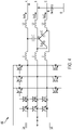
FIG. 4 shows an example power converter used for implementing a 3-wire AHF; -
FIG. 5 shows an example parallel system of 3-wire and 4-wire AHFs; -
FIG. 6A shows an example implementation of how zero and non-zero current components may be distributed between the 3-wire and 4-wire AHF with priority given to 4-wire units; -
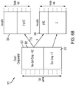
FIG. 6B shows another example implementation of how zero and non-zero current components may be distributed between the 3-wire and 4-wire AHF with priority given to 4-wire units; -
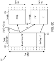
FIG. 6C shows another example implementation of how zero and non-zero current components may be distributed between the 3-wire and 4-wire AHF with priority given to 4-wire units; -
FIG. 6D shows another example implementation of how zero and non-zero current components may be distributed between the 3-wire and 4-wire AHF with priority given to 4-wire units; -
FIG. 7A shows another example of how zero and non-zero current components may be distributed between the 3-wire and 4-wire AHF with priority of non-zero compensation given to 3-wire AHF units first; -
FIG. 7B shows another example of how zero and non-zero current components may be distributed between the 3-wire and 4-wire AHF with priority of non-zero compensation given to 3-wire AHF units first; -
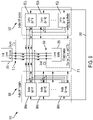
FIG. 8 shows an example implementation of a paralleling method; -
FIG. 9 shows an alternative implementation of the paralleling method (e.g., with master controller role implemented by one of the units in the parallel system); -
FIG. 10 shows an example control method for a single 3 or 4-wire AHF; -
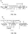
FIG. 11A shows an example technique to calculate AHF compensation reference currents (open-loop method); -
FIG. 11B shows another example technique to calculate AHF compensation reference currents (closed-loop method); -
FIG. 12 shows an example of a master controller's control computations occurring, for example, at a fundamental period T1; -
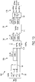
FIG. 13 shows example 4-wire slave units control computations occurring, for example, at a fundamental period T1; and -
FIG. 14 shows example 3-wire slave units control computations occurring, for example, at a fundamental period T1. - The features and other details of the concepts, systems, and techniques sought to be protected herein will now be more particularly described. It will be understood that any specific embodiments described herein are shown by way of illustration and not as limitations of the disclosure and the concepts described herein. Features of the subject matter described herein can be employed in various embodiments without departing from the scope of the concepts sought to be protected.
- As briefly discussed in the Background section of this disclosure, a 3-phase active harmonic filter (AHF) can be classified into one of two types: 4-wire AHF and 3-wire AHF, depending on its capability to provide neutral current compensation. A 4-wire AHF has a 4-wire output terminal (the three regular phases A, B, and C, and neutral (N)) and can compensate the three regular phases as well as neutral, while a 3-wire AHF has a 3-wire output terminal (A, B, C) with no neutral output connection.
-
FIG. 1 shows an example 4-wire AHF system 100 andFIG. 2 shows an example 3-wire AHF system 200. In both systems, a set of current transformers (CTs) or current sensors are used to measure the 3-phase currents either at the source side or at the load side. The AHFs use the information from these CTs to generate compensation currents to achieve the desired objectives. The choice whether to use load CTs or source CTs depends on the reference generation techniques used, which will be discussed later in this disclosure. -
FIG. 3 shows a typical 3-level power converter 300 (shown as a T-type) used in a 4-wire AHF, whileFIG. 4 shows its typical use in a 3-wire AHF 400. Each is equipped with an output filter circuit consisting of a network of inductors and capacitors (shown as an L-C-L type). The specific power converter and filter topology are shown only as example implementations. The neutral point output of the active filter (N) may be connected to the mid-point of the DC bus capacitors. - Note that, if the neutral connection terminal (N) of a 4-wire AHF is not connected to the system neutral, then a typical 4-wire AHF as shown in
FIG. 3 can also function as a 3-wire AHF In other words, most 4-wire AHFs can function as both a 4-wire AHF as well as a 3-wire AHF Despite this, in some examples it may be commercially advantageous to use an AHF designed specifically for 3-wire only such as shown inFIG. 4 since such AHFs are more economical to build than a 4-wire AHF with comparable capacity due to the following reasons. Firstly, a 4-wire AHF must accommodate the extra neutral phase conductor which needs to be as large as three times the phase currents to account for worst-case neutral current. Secondly, a 3-wire AHF can take advantage of the 3-wire nature of the power converter and use the well-known 3-wire pulse-width-modulation (PWM) technique which allows switching of only two out of three legs at a single instance of time, thereby reducing the amount of PWM switching losses by 1/3. This in turn can reduce the sizing requirements of the power switches (e.g., insulated-gate bipolar transistors [IGBTs]). Lastly, due to the 3-wire connections, 3-wire AHFs can use only two internal current sensors instead of the three sensors required in a 4-wire AHF, thereby reducing costs. - With 3-wire AHFs being more economical to build and manufacture, but 4-wire AHFs still being required for neutral current compensation, there can arise a need to have both types of AHF coexist in a parallel-connected system.
FIG. 5 shows such asystem 500 in which a parallel network of m units of 4-wire AHFs are used in combination with n units of 3-wire AHFs. Each of the units can have different ampacity ratings. As in the single unit systems shown inFIG. 1 andFIG. 2 , the goal of the parallel system is to compensate the load currents (iloada, iloadb, and iloadc ) such that the source currents (isrca, isrcb, and isrcc ) can be free of harmonics or achieve desired power factor and/or balanced conditions. To prevent circulating current and unnecessary loading of each of the units, the total 3-wire units currents (i a3w , i b3 w, and i c3w ) may be shared amongst the 3-wire units by the proportion of each unit size. Similarly, the total 4-wire units currents (i a4w , i b4w , and i c4w ) shall be shared amongst the 4-wire units by the proportion of each unit size. - An example way of operating paralleled 3-wire and 4-wire AHFs as in
FIG. 5 is to restrict the 4-wire units to produce only the zero component (neutral component) of the compensation current and to let the 3-wire units produce all of the non-zero component. An advantage of this method is that the 3-wire and 4-wire units can work independently, and no communication is needed between the two systems to achieve a correct paralleling. However, this method may not allow for a full utilization of the output capacity (for example, amperage capacity) of all the units in the system. For example, at times when there are no zero components of the load being present (e.g., when no 4-wire loads are flowing in the system), the 4-wire units may be left unused, even when the 4-wire units have the capability to produce non-zero components of the currents. With this method, the 4-wire units cannot be used to increase the total capacity of the 3-wire units, even when it has the capability to do so. Note that since most of the zero components may be triplen harmonics, a variation of this technique also includes letting the 4-wire units output only the triplen harmonics and leaving the rest (non-triplen) to be handled by the 3-wire units. - Examples of this disclosure include a method for parallel-mixing 3-wire AHFs and 4-wire AHFs to increase utilization of the amperage capacity of each of the units in a parallel system. In one example implementation, the method allocates all zero-component current to the 4-wire units. The method splits the non-zero components into proportions to be implemented by the 4-wire units and the 3-wire units such that each of the units in the parallel system can be loaded up to its respective capacity. Various examples include calculating a ratio p < 1.0 equaling a proportion of the non-zero compensation current to be implemented by the 4-wire units such that the 4-wire units' capacity can be more fully utilized. The remaining proportion (1-p) of the non-zero components may be allocated to the 3-wire units.
-
FIGS. 6A-6D each illustrate a block diagram of a distribution scheme of zero and non-zero compensation current in a parallel system according to an example.FIG. 6A illustrates a block diagram of a firstcurrent compensation scheme 600 according to an example. The firstcurrent compensation scheme 600 illustrates an overall current 602 being divided between, or assigned to, one or more 3-wire units 604 and one or more 4-wire units 606. The one or more 3-wire units 604 and one or more 4-wire units 606 may provide compensation current to a load in the assigned amount. The overall current 602 includes anon-zero component 608 and a zerocomponent 610. - Under the first
current compensation scheme 600, the entirety of the overall current 602 is assigned to the one or more 4-wire units 606. In various examples, the one or more 4-wire units 606 are given priority over the one or more 3-wire units 604 to provide compensation current. For example, if the overall current 602 is within the total capacity of the one or more 4-wire units 606, the entirety of the overall current 602 may be assigned to the one or more 4-wire units 606 as illustrated in the firstcurrent compensation scheme 600. -
FIG. 6B illustrates a secondcurrent compensation scheme 612 according to an example. Under the secondcurrent compensation scheme 612, the zerocomponent 610 is assigned to the one or more 4-wire units 606, and thenon-zero component 608 is divided between the one or more 3-wire units 604 and the one or more 4-wire units 606. In various examples, the one or more 4-wire units 606 are given priority over the one or more 3-wire units 604 to provide compensation current. A remaining capacity of the one or more 4-wire units 606 may be utilized to provide a portion p of thenon-zero component 608, until the one or more 4-wire units 606 are at capacity. A remainder of the non-zero component 608 (1-p) may be assigned to the one or more 3-wire units 606. Examples of determining the ratio p are discussed in greater detail below. -
FIG. 6C illustrates a thirdcurrent compensation scheme 614. Under the thirdcurrent compensation scheme 614, the zerocomponent 610 is assigned to the one or more 4-wire units 606, and thenon-zero component 608 is divided between the one or more 3-wire units 604 and the one or more 4-wire units 606. In various examples, the one or more 4-wire units 606 are given priority over the one or more 3-wire units 604 to provide compensation current. A remaining capacity of the one or more 4-wire units 606 may be utilized to provide a portion p of thenon-zero component 608, until the one or more 4-wire units 606 are at capacity. A remainder of the non-zero component 608 (1-p) may be assigned to the one or more 3-wire units 604. However, in the thirdcurrent compensation scheme 614, both the one or more 3-wire units 604 and the one or more 4-wire units 606 may be at capacity. -
FIG. 6D illustrates a fourthcurrent compensation scheme 616. Under the fourthcurrent compensation scheme 616, the zerocomponent 610 is assigned to the one or more 4-wire units 606, which may consume the entire capacity of the one or more 4-wire units 606. In some examples, the zerocomponent 610 may exceed the capacity of the one or more 4-wire units 606. Thenon-zero component 608 is assigned to the one or more 3-wire units 604, which may also consume the entire capacity of the one or more 3-wire units 604. - Accordingly, in various examples, the one or more 4-
wire units 606 may be given priority in the allocation of the non-zero components of the compensation. For example, in some implementations, only after the one or more 4-wire units 606 have been fully loaded to their full capacities will the remainder of thenon-zero component 608 be allocated to the one or more 3-wire units 604. An alternative of this method is also possible, for example, in which the priority of the allocation of thenon-zero component 608 is first given to the one or more 3-wire units 604. For example,FIG. 7A illustrates a fifthcurrent compensation scheme 700 in which thenon-zero component 608 is first provided to the one or more 3-wire units 604, and the zerocomponent 610 is provided to the one or more 4-wire units 606. In the fifthcurrent compensation scheme 700, thenon-zero component 608 may be less than a capacity of the one or more 3-wire units 604.FIG. 7B illustrates a sixthcurrent compensation scheme 702, which is substantially similar to the fifthcurrent compensation scheme 700 but in which the one or more 3-wire units 604 receive a full allocation of the non-zero component 608 (for example, because the one or more 3-wire units 604 are at a full capacity) and the one or more 4-wire units 606 receive a remainder of thenon-zero component 608 while still receiving the zerocomponent 610. -
FIG. 8 illustrates a block diagram of apower system 800 according to an example. Thepower system 800 includes one or more 3-wire AHFs 802 ("3-wire units 802"), one or more 4-wire AHFs 804 ("4-wire units 804"), at least one 3-phase, 4-wire AC source 806 ("AC source 806"), one or more 4-wire loads 808 ("load 808"), at least onecontroller 810, one or more source CTs 812 ("source CTs 812"), and one or more load CTs 814 ("load CTs 814"). TheAC source 806 is coupled to, and is configured to provide AC power to, theloads 808. Theunits loads 808. Thesource CTs 812 are coupled to, and are configured to measure a current output by, theAC source 806. Theload CTs 814 are coupled to, and are configured to measure a current provided to, theload 808. - The
controller 810 is communicatively coupled to the 3-wire units 802, the 4-wire units 804, thesource CTs 812, and theload CTs 814. Although a communicative coupling between thecontroller 810 and theCTS controller 810 may be communicatively coupled to theCTs controller 810 is a component of at least one of theunits source CTs 812 and loadCTs 814 are configured to provide source-current information and load-current information, respectively, to thecontroller 810. Thecontroller 810 is configured to determine a total compensation current to achieve desired AHF objectives, such as harmonics compensation, power-factor correction, load balancing, and so forth. Thecontroller 810 decomposes the total compensation current into zero and non-zero components. Thecontroller 810 may implement any of the current compensation schemes discussed above. For example, thecontroller 810 may allocate the zero component of the total compensation current to the 4-wire units 804. Thecontroller 810 may also calculate a ratio p indicating a distribution of the non-zero component between theunits - To determine the ratio p, the
controller 810 may access information regarding the total capacity of the 4-wire units 804 and the 3-wire units 802. This information can be shared amongst theunits controller 810. For example, the 3-wire units 802 and 4-wire units 804 may be bidirectionally communicatively coupled to each other via a wired orwireless communication medium 816. In some examples, this bidirectional communication can be used to share voltage- and current-metering information for display purposes, alarms, faults, and so forth, as well as sharing commands and settings amongst theunits controller 810 may broadcast the total compensation current information on a separate fast-communication bus 818 along with the ratio p and a total capacity of each of the 3-wire units 802 and 4-wire units 804. In some examples, however, thecontroller 810 may use the wired orwireless communication medium 816 to broadcast the total compensation current information along with the ratio p and a total capacity of each of the 3-wire units 802 and 4-wire units 804 (for example, if enough bandwidth is available on the wired orwireless communication medium 816 and the timeliness of delivering the information is not a concern). Using the information, each of theunits units - It is to be appreciated that in some examples, the
controller 810 may be physically distinct from theunits controller 810 may be a component of one or more of theunits units controller 810 may be a master controller configured to perform the processes discussed above, and each of theunits units FIG. 9 illustrates an example of apower system 900 in which each of theunits unit 802n acts as a master unit (for example, by including a master controller substantially similar or identical to the controller 810). In some examples, the load- and source-current information can be wired to one or more of theunits units power system 800. - In various examples, each of the
units FIG. 10 illustrates a block diagram of anAHF control scheme 1000 according to one example. Areference generation block 1002 generates reference currents 1004 (irefa, irefb, and irefc ) based on measured system currents 1006 (IloadA/IsrcA, IloadB/IsrcB, IloadC/IsrcC), which may be received from thesource CTs 812 and theload CTs 814, and terminal voltages 1008 (van, vbn, vcn) across the phase lines provided to theload 808. A converter-controller block 1010 produces PWM gate signals 1012 to be provided to theunits 802, 804 (for example, to switches in theunits 802, 804) such that the output currents 1004 (IoutA, IoutB, IoutC) follow the references and maintain a desired DC-bus voltage. - The converter-
controller block 1010 includes adynamic feedback controller 1012, a DC-bus-voltage controller 1014, and a PWM-modulation controller 1016. Thedynamic feedback controller 1012 is configured to reduce an error between the reference current and an output current to approximately zero, and outputs command-voltage signals 1018 (vCmdA, vCmdB, vCmdC) indicative thereof. The DC-bus-voltage controller 1014 is configured to regulate a DC-bus voltage. The PWM-modulation controller 1016 is configured to determine or calculate the PWM gate signals 1012 based on the command-voltage signals 1018. - Various techniques may be implemented to compute the
reference compensation currents 1004 for an active harmonic filter. For example,FIG. 11A illustrates a block diagram of a current-computation technique 1100 using a fast Fourier transform (FFT) method, in which thereference compensation currents 1004 are calculated from the inverse FFT of the measured load currents (for example, each phase current provided to theload 808 and measured by the load CTs 814) through a process known as an open-loop method. Processing of the load currents' FFT spectrums in an open-loop method may include removing the fundamental harmonics or higher-order harmonics as well as RMS-limiting of the total compensation spectrum. If desired, the fundamental-frequency compensation such as reactive-current compensation or load balancing may also be incorporated. Various known techniques to calculate these fundamental-frequency compensation currents exist and will not be discussed here. Alternatively, the harmonics processing can be done as shown inFIG. 11B which is known as a closed-loop method. In the closed-loop method, the measured source currents (for example, each phase current provided by theAC source 806 and measured by the source CTs 812) instead are used. For each of the harmonics above a fundamental frequency that are desired to be controlled, a closed-loop PI controller is used to force each of the source current harmonics to zero as shown inFIG. 11B. FIG. 11B illustrates a block diagram of a second current-computation technique 1102 using an FFT method. - With reference to
FIG. 8 , suppose the reference currents for the total output currents of the 3-wire units 802 are given by iref a3 w, iref b3 w, and irefc3w. Similarly, suppose the reference currents for the total output currents of the 4-wire units 804 are given by irefa4w, irefb4w, and irefc4w. The reference currents for the total compensation currents irefa, irefb, and irefc' can then be expressed as:


- Also, suppose a capacity (for example, an amperage rating) of an arbitrary i-th 3-wire unit of the 3-
wire units 802 is given by cap3wi and of an arbitrary i-th 4-wire unit of the 4-wire units 804 is given by cap4wi , then the total capacity of the 3-wire units 802 and the 4-wire units 804 are:

units wire units 802 and the 4-wire units 804 should be calculated from the respective unit type as:

- In some examples, the reference currents for the
units 



- It can be seen that irefα + irefβ + irefγ = 0 or irefγ = -irefα - irefβ. Since irefγ can be derived from irefα and irefβ, this third component of the non-zero current may be dropped. The remaining two non-zero components irefα and irefβ along with iref 0 may be used to define the original 3-phase quantities. In various examples, irefα, irefβ, and iref 0 as defined in (6.a), (6.b), and (4) are similar to the standard abc-to-dq0 stationary reference frame transformation (Park transformation), or Clarke transformation, and these standard transformations can also be used to obtain the decomposition of the reference currents into the zero and non-zero components.
- With the zero component for the 4-wire units reference currents (iref04w) defined as in (5), the non-zero components of the reference currents are:




- For the 3-
wire units 802, the non-zero components of the reference currents are identical to the abc phase currents since the zero component iref 03w = 0


- In various examples, the zero component of the reference current is first assigned to the 4-
wire units 804 as given in (5), with the constraint that the RMS magnitude is limited to the total 4-wire capacity cap4w, that is:
- Once the zero current is allocated, the non-zero components of the reference currents (irefa, irefβ, and irefγ ) may be divided between the 4-
wire units 804 and 3-wire units 802. In various examples, the remaining capacity of the 4-wire units 804 is first used in allocating the non-zero components of the reference currents (irefα, irefβ, and irefγ ) before allocating the non-zero components of the reference currents (irefa, irefβ, and irefγ ) to the 3-wire units 802. For example, a ratio p of the non-zero component of the 4-wire output may be defined with respect to the total non-zero components.


- To fully utilize the capacity (for example, the amperage capacity) of the 4-
wire units 804, a ratio p may be determined that satisfies the following constraints:


- To determine p, equations (13a-13c) may be transformed into the frequency domain using the FFT technique. The squared RMS values of (13a-13c) in the frequency domain in terms of the harmonic's spectrum is given by


- The ratio p that satisfies (14) then can be found from:


- Collecting the real and imaginary parts of (17) yields,


- Equation (20) may be rewritten as,




- Using (21) in (15.a) yields,


- If (24) has no real solutions, that is, D ≡ B2 - 4A(C - cap4w 2) < 0 then pa = 1. This corresponds to cases in
FIG. 6A andFIG. 7A . In summary,
h in the expression for A and B in (22) with Iβh and Iγh respectively. -
FIG. 12 ,FIG. 13 , andFIG. 14 show diagrams of control computations that may be performed by one or more controllers. In some examples, thecontroller 810 executes the control computations ofFIGS. 12-14 . In various examples, each of theunits FIGS. 12-14 . In at least one example, the control computations ofFIGS. 12-14 may be performed by each of the controllers at each fundamental harmonic periodic cycle of the source voltage T1, that is, the AC voltage provided by the AC source 806 (for example, every 20ms or 16.667ms for a 50Hz or 60Hz AC signal, respectively). In some examples, T1 can be determined using a phase-locked loop. -
FIG. 12 illustrates a control diagram indicative of acontrol scheme 1200 according to an example. In at least one example, thecontrol scheme 1200 may be executed by thecontroller 810, which may be internal or external to at least one of theunits controller 810 may execute thecontrol scheme 1200 repeatedly, such as at every period T1 of an AC voltage received from theAC source 806. - The
controller 810 receivescurrent information 1202 from thesource CTs 812 and/or loadCTs 814 indicative of source currents and load currents, respectively, on each phase. In various examples, the currents are sampled at the rate of N-times the fundamental period T1 and stored into memory buffers of length N. At afirst control block 1204, thecontroller 810 determines N. For efficient computation N may be chosen as a power of 2. By the Nyquist theorem, N may be chosen to be greater than 2 times the harmonic frequencies of interest to be controlled, denoted as Nh. For example, if it is desired to control harmonics up to 50th harmonics then Nh=50, which requires N > 2 x Nh = 100. In this example, the smallest N that is also a power of 2 is equal to 128. The FFT calculations results are the harmonic spectrum denoted by N/2 complex numbers
first control block 1204 yields the complex currents Iai , Ibi, Ibi 1206 which are provided to asecond control block 1208. - At the
second control block 1208, the harmonic spectrum Iai, Ibi , Ibi i = 1, ..., Nh is used to compute and output totalload compensation currents 1210 based on the AHF objectives (harmonic compensation, power factor correction, or load balancing) using the open-loop or closed loop method as inFIGS. 11A or 11B , respectively, resulting in the complex harmonic spectrum of the reference currents: Irefai, Irefbi, Irefci, i = 1, ..., Nh. For power factor correction, phase-to-neutral voltages van, vbn, and vcn 1212 from theAC source 806 are received from at least one voltage sensor. - The total
load compensation currents 1210 are provided to athird control block 1214. At thethird control block 1214, the zero and non-zero components of the complex harmonic spectrum are computed using equations (4) and (6) as follows for i = 1, ...,Nh:


- The
third control block 1214 outputs the reference currents (Irefαi, Irefβi, Iref 0i ) 1216. The zero-current reference Iref 0i is provided to an RMS-limitingblock 1218. At the RMS-limitingblock 1218, the complex harmonic spectrum of the zero-current reference Iref 0 i is limited such that the total RMS of the zero current is less than the total capacity of the 4-wire units 804 cap4w.

- The RMS-limiting
block 1218 outputs a limited zero-current reference Iref' 0i 1220. Thethird control block 1214 provides the non-zero components of the reference currents (Irefαi, Irefβi, Iref 0i ) 1216, and the RMS-limitingblock 1218 provides the limited zero-current reference Iref' 0i 1220, to each of theunits controller 810, if applicable. The RMS-limitingblock 1218 also provides the limited zero-current reference Iref' 0i 1220 to a ratio-calculator block 1222. - The ratio-
calculator block 1222 determines aratio p 1224 indicative of a distribution of the non-zero current between theunits calculator block 1222 uses equations (16), (22), and (26) to determine theratio p 1224. The ratio-calculator block 1222 may determine theratio p 1224 based on a capacity of the 4-wire units 804 and based on the non-zero components of the reference currents (Irefαi, Irefβi, Iref 0i ) 1216 and the limited zero-current reference Iref' 0i 1220, as discussed above. The ratio-calculator block 1222 may broadcast theratio p 1224 to each of theunits controller 810, if applicable.Output information 1226 collectively broadcast by thecontroller 810 to the slave units therefore includes the non-zero reference currents (Irefαi, Irefβi ), the limited zero-current reference Iref' 0 i, the ratio p, capacity information for 3-wire units cap3w, and capacity information for 4-wire units cap4w. - Upon receiving the data from the
controller 810, the slave units execute control computations.FIG. 13 illustrates a control diagram of acontrol scheme 1300 executed by 4-wire slave units of the 4-wire units 804. The 4-wire slave unit receives theoutput information 1226. At afirst control block 1302, the non-zero reference harmonic spectrum is scaled by p:

- The scaled non-zero reference
harmonic spectrum 1304 is provided to asecond control block 1306. At thesecond control block 1306,local reference currents 1308 are derived for the unit by multiplying the scaled non-zero referenceharmonic spectrum 1304 with the ratio of the unit's own respective capacity compared to the total 4-wire unit capacity cap4w:
- At a
third control block 1310, thelocal reference currents 1308 are transformed back to the abc space to generate transformed reference currents 1312:


- At a
fourth control block 1314, an N-point inverse FFT is executed to obtain the time domain reference currents iref4wa, iref4wb, andiref 4wc 1316 for the unit to use in the AHF-control scheme 1000 discussed above. In various examples, the DC content and harmonic spectrum greater than Nh-th harmonic may be set to zero at this step. -
FIG. 14 illustrates a control diagram of acontrol scheme 1400 executed by 3-wire slave units of the 3-wire units 802. Thecontrol scheme 1400 is similar to thecontrol scheme 1300. However, as the zero component of the reference currents is zero, afirst control block 1402, the non-zero reference harmonic spectrum is scaled by (1-p):

- A scaled non-zero reference
harmonic spectrum 1404 is provided to asecond control block 1406, at which the total RMS of the non-zero currents are limited to the total capacity of the 3-wire units 802 cap3w as follows:

- The remainder of the
control scheme 1400 may be substantially similar or identical to thecontrol scheme 1300, except that a zero component of current is omitted, and is not repeated for purposes of brevity. - As described above and as will be appreciated by those of ordinary skill in the art, embodiments of the disclosure herein may be configured as a system, method, or combination thereof. Accordingly, embodiments of the present disclosure may be comprised of various means including hardware, software, firmware or any combination thereof.
- It is to be appreciated that the concepts, systems, circuits and techniques sought to be protected herein are not limited to use in the example applications described herein but rather, may be useful in substantially any application where it may be desired to distribute reference current in a system including one or more 3-wire AHFs and one or more 4-wire AHFs arranged in a parallel configuration. As discussed above, in certain systems there can arise a desire to have 3-wire AHFs and 4-wire AHFs connected in parallel. Examples discussed above include a method for parallel-mixing 3-wire AHFs and 4-wire AHFs to increase utilization of the amperage capacity of each of the units in a parallel system. In one example implementation, the method allocates all zero-component current to the 4-wire units. The method may split the non-zero components into proportions to be implemented by the 4-wire units and the 3-wire units such that each of the units in the parallel system can be loaded up to its respective capacity. Various examples include calculating a ratio p < 1.0 equaling a proportion of the non-zero compensation current to be implemented by the 4-wire units such that the 4-wire units' capacity can be more fully utilized. The remaining proportion (1-p) of the non-zero components may be allocated to the 3-wire units.
- While particular examples and applications of the present disclosure have been illustrated and described, it is to be understood that embodiments of the disclosure not limited to the precise construction and compositions disclosed herein and that various modifications, changes, and variations can be apparent from the foregoing descriptions without departing from the spirit and scope of the disclosure as defined in the appended claims.
- Having described preferred embodiments, which serve to illustrate various concepts, structures and techniques that are the subject of this patent, it will now become apparent to those of ordinary skill in the art that other embodiments incorporating these concepts, structures and techniques may be used. Additionally, elements of different embodiments described herein may be combined to form other embodiments not specifically set forth above.
- Accordingly, it is submitted that the scope of the patent should not be limited to the described embodiments but rather should be limited only by the scope of the following claims.
Claims (15)
- A power system comprising:at least one three-wire active harmonic filter (AHF) configured to be coupled to, and provide compensation current to, a three-phase load;at least one four-wire AHF configured to be coupled to, and provide compensation current to, the three-phase load; anda controller configured todetermine a total compensation current to provide to the three-phase load, the total compensation current including a zero component and a non-zero component;determine an output capacity of the at least one three-wire AHF and the at least one four-wire AHF;calculate a current-compensation ratio based on the output capacity of the at least one three-wire AHF and the at least one four-wire AHF; andcontrol the at least one four-wire AHF to provide at least a portion of the non-zero component of the total compensation current to the three-phase load based on the current-compensation ratio.
- The power system of claim 1, wherein the at least one three-wire AHF is coupled in parallel with the at least one four-wire AHF
- The power system of claim 1, wherein the controller is further configured to control the at least one four-wire AHF to provide a zero compensation current to the three-phase load to satisfy the zero component of the total compensation current.
- The power system of claim 3, wherein the controller is configured to:determine a remaining capacity of the at least one four-wire AHF after allocating the zero component of the total compensation current to the at least one four-wire AHF; anddetermine whether the remaining capacity of the at least one four-wire AHF exceeds the non-zero component of the total compensation current.
- The power system of claim 4, wherein the controller is configured to allocate an entirety of the total compensation current to the at least one four-wire AHF responsive to determining that the remaining capacity of the at least one four-wire AHF exceeds the non-zero component of the total compensation current.
- The power system of claim 5, wherein the current-compensation ratio is one, and wherein the at least one three-wire AHF does not provide a compensation current to the three-phase load.
- The power system of claim 4, wherein the controller is configured to allocate the remaining capacity of the at least one four-wire AHF to non-zero compensation current responsive to determining that the non-zero component of the total compensation current exceeds the remaining capacity of the at least one four-wire AHF
- The power system of claim 7, wherein the at least a portion of the non-zero component of the total compensation current is a first portion of non-zero compensation current provided to the three-phase load, and wherein a remaining portion of the non-zero compensation current is allocated to the at least one three-wire AHF
- The power system of claim 8, wherein the current-compensation ratio is equal to the first portion of the non-zero compensation current divided by the non-zero compensation current.
- A method of operating a power system including at least one three-wire active harmonic filter (AHF) and at least one four-wire AHF, each being configured to be coupled to, and provide compensation current to, a three-phase load, the method comprising:determining a total compensation current to provide to the three-phase load, the total compensation current including a zero component and a non-zero component;determining an output capacity of the at least one three-wire AHF and the at least one four-wire AHF;calculating a current-compensation ratio based on the output capacity of the at least one three-wire AHF and the at least one four-wire AHF; andcontrolling the at least one four-wire AHF to provide at least a portion of the non-zero component of the total compensation current to the three-phase load based on the current-compensation ratio.
- The method of claim 10, further comprising controlling the at least one four-wire AHF to provide a zero compensation current to the three-phase load to satisfy the zero component of the total compensation current.
- The method of claim 11, further comprising:determining a remaining capacity of the at least one four-wire AHF after allocating the zero component of the total compensation current to the at least one four-wire AHF; anddetermining whether the remaining capacity of the at least one four-wire AHF exceeds the non-zero component of the total compensation current.
- The method of claim 12, further comprising allocating an entirety of the total compensation current to the at least one four-wire AHF responsive to determining that the remaining capacity of the at least one four-wire AHF exceeds the non-zero component of the total compensation current.
- The method of claim 12, further comprising allocating the remaining capacity of the at least one four-wire AHF to non-zero compensation current responsive to determining that the non-zero component of the total compensation current exceeds the remaining capacity of the at least one four-wire AHF
- A non-transitory computer-readable medium storing thereon sequences of computer-executable instructions for executing the method of any of claims 10-14.
Applications Claiming Priority (2)
| Application Number | Priority Date | Filing Date | Title |
|---|---|---|---|
| US202163181668P | 2021-04-29 | 2021-04-29 | |
| US17/489,245 US11735917B2 (en) | 2021-04-29 | 2021-09-29 | Systems and methods for paralleling 3-wire and 4-wire 3-phase active harmonic filters |
Publications (3)
| Publication Number | Publication Date |
|---|---|
| EP4084256A1 true EP4084256A1 (en) | 2022-11-02 |
| EP4084256B1 EP4084256B1 (en) | 2025-11-19 |
| EP4084256C0 EP4084256C0 (en) | 2025-11-19 |
Family
ID=81345933
Family Applications (1)
| Application Number | Title | Priority Date | Filing Date |
|---|---|---|---|
| EP22169424.3A Active EP4084256B1 (en) | 2021-04-29 | 2022-04-22 | Systems and methods for paralleling 3-wire and 4-wire 3-phase active harmonic filters |
Country Status (5)
| Country | Link |
|---|---|
| US (1) | US11735917B2 (en) |
| EP (1) | EP4084256B1 (en) |
| CN (1) | CN115276009B (en) |
| AU (1) | AU2022202736B2 (en) |
| CA (1) | CA3156528C (en) |
Families Citing this family (1)
| Publication number | Priority date | Publication date | Assignee | Title |
|---|---|---|---|---|
| CN116582005B (en) * | 2023-04-18 | 2023-12-08 | 西安麦格米特电气有限公司 | Electric energy conversion circuit, electric energy conversion method and electric energy conversion equipment |
Citations (1)
| Publication number | Priority date | Publication date | Assignee | Title |
|---|---|---|---|---|
| CN107658876A (en) * | 2017-11-16 | 2018-02-02 | 兰州理工大学 | Unified power quality adjusting device and control method |
Family Cites Families (6)
| Publication number | Priority date | Publication date | Assignee | Title |
|---|---|---|---|---|
| JP3378410B2 (en) * | 1995-06-29 | 2003-02-17 | 日本放送協会 | Active filter |
| KR200379908Y1 (en) * | 2004-12-30 | 2005-03-24 | 전력품질기술주식회사 | 3 Phase 4 Wire Hybrid Active Power Filter |
| WO2013102782A1 (en) | 2012-01-05 | 2013-07-11 | American Power Conversion Corporation | Methods and apparatus for controlling power converters in parallel connection |
| CN103166224B (en) * | 2013-04-11 | 2014-10-01 | 武汉大学 | A method for optimizing the output inductance of a three-phase four-wire shunt active power filter |
| US20200003809A1 (en) * | 2018-06-27 | 2020-01-02 | Schneider Electric USA, Inc. | Neutral connection detection method for 3/4 -wire active filters |
| CN110048425A (en) * | 2019-05-07 | 2019-07-23 | 哈尔滨理工大学 | APF and electric current detecting method based on the combination of MLDCL and H bridge |
-
2021
- 2021-09-29 US US17/489,245 patent/US11735917B2/en active Active
-
2022
- 2022-04-22 EP EP22169424.3A patent/EP4084256B1/en active Active
- 2022-04-26 CA CA3156528A patent/CA3156528C/en active Active
- 2022-04-26 AU AU2022202736A patent/AU2022202736B2/en active Active
- 2022-04-29 CN CN202210473089.8A patent/CN115276009B/en active Active
Patent Citations (1)
| Publication number | Priority date | Publication date | Assignee | Title |
|---|---|---|---|---|
| CN107658876A (en) * | 2017-11-16 | 2018-02-02 | 兰州理工大学 | Unified power quality adjusting device and control method |
Non-Patent Citations (1)
| Title |
|---|
| GUCIZHU CHEN ET AL: "Unified power quality conditioner for distribution system without reference calculations", POWER ELECTRONICS AND MOTION CONTROL CONFERENCE, 2004. CONFERENCE PROC EEDINGS. IPEMC 2004. THE 4TH INTERNATIONAL XI'AN, CHINA AUG. 14-16, 2004, PISCATAWAY, NJ, USA,IEEE, vol. 3, 14 August 2004 (2004-08-14), pages 1201 - 1206, XP010756002, ISBN: 978-7-5605-1869-5 * |
Also Published As
| Publication number | Publication date |
|---|---|
| CN115276009B (en) | 2024-08-02 |
| EP4084256B1 (en) | 2025-11-19 |
| US20220360077A1 (en) | 2022-11-10 |
| CN115276009A (en) | 2022-11-01 |
| US11735917B2 (en) | 2023-08-22 |
| CA3156528A1 (en) | 2022-10-29 |
| EP4084256C0 (en) | 2025-11-19 |
| AU2022202736A1 (en) | 2022-11-17 |
| AU2022202736B2 (en) | 2024-02-01 |
| CA3156528C (en) | 2025-04-08 |
Similar Documents
| Publication | Publication Date | Title |
|---|---|---|
| US9812862B2 (en) | Paralleling of active filters with independent controls | |
| US9190846B2 (en) | Power quality management system and methods of controlling phase unbalance | |
| US20200204057A1 (en) | Power conversion device and power conversion system | |
| JP6818766B2 (en) | Reactive power control device and reactive power control method | |
| US20200195037A1 (en) | Charging apparatus capable of reducing low frequency leakage current | |
| JP2001506385A (en) | Flicker controller using voltage source converter | |
| CN107086590B (en) | Coordinated control method, device and transmission system for hybrid DC station control | |
| US6348778B1 (en) | Method and apparatus for improving the voltage quality of secondary power supply unit | |
| US11967891B2 (en) | Mitigation of harmonic disturbances in a power converter | |
| EP4084256B1 (en) | Systems and methods for paralleling 3-wire and 4-wire 3-phase active harmonic filters | |
| JPH08228480A (en) | Method and equipment for controlling converter station compensated in series | |
| EP3588725B1 (en) | Active power filter with adjustable neutral current limit | |
| AU2019204473A1 (en) | Neutral Connection Detection Method For 3/4 -Wire Active Filters | |
| EP4250527B1 (en) | Electric power conversion apparatus and estimation apparatus | |
| CN114142493A (en) | Power self-balancing control method, device and storage medium | |
| EP3514942B1 (en) | Power supply system | |
| JP3316860B2 (en) | Power converter | |
| US6205042B1 (en) | Indirect calculation of bus voltage for voltage source inverter | |
| RU2512886C1 (en) | Device to compensate high harmonics and correct grid power ratio | |
| US12476469B2 (en) | Electric power control system simulating a synchronous generator | |
| KR101916947B1 (en) | Apparatus for measuring a three-phase root mean square output in a power system | |
| CN121791186A (en) | Flexible transformer system containing medium-voltage direct-current converter and voltage regulating method | |
| Sasikanth et al. | Power Quality Improvement in AC-DC Networks using PWM and Hysteresis Control for Railway Applications | |
| JP2000041335A (en) | Control method for active filter | |
| BIROU et al. | Power Electronic Converters–New Trends in Power Quality of Low Voltage Power Grids |
Legal Events
| Date | Code | Title | Description |
|---|---|---|---|
| PUAI | Public reference made under article 153(3) epc to a published international application that has entered the european phase |
Free format text: ORIGINAL CODE: 0009012 |
|
| STAA | Information on the status of an ep patent application or granted ep patent |
Free format text: STATUS: THE APPLICATION HAS BEEN PUBLISHED |
|
| AK | Designated contracting states |
Kind code of ref document: A1 Designated state(s): AL AT BE BG CH CY CZ DE DK EE ES FI FR GB GR HR HU IE IS IT LI LT LU LV MC MK MT NL NO PL PT RO RS SE SI SK SM TR |
|
| STAA | Information on the status of an ep patent application or granted ep patent |
Free format text: STATUS: REQUEST FOR EXAMINATION WAS MADE |
|
| 17P | Request for examination filed |
Effective date: 20230418 |
|
| RBV | Designated contracting states (corrected) |
Designated state(s): AL AT BE BG CH CY CZ DE DK EE ES FI FR GB GR HR HU IE IS IT LI LT LU LV MC MK MT NL NO PL PT RO RS SE SI SK SM TR |
|
| GRAP | Despatch of communication of intention to grant a patent |
Free format text: ORIGINAL CODE: EPIDOSNIGR1 |
|
| STAA | Information on the status of an ep patent application or granted ep patent |
Free format text: STATUS: GRANT OF PATENT IS INTENDED |
|
| RIC1 | Information provided on ipc code assigned before grant |
Ipc: H02M 1/42 20070101ALI20250604BHEP Ipc: H02J 3/46 20060101ALI20250604BHEP Ipc: H02J 3/01 20060101ALI20250604BHEP Ipc: H02J 3/18 20060101AFI20250604BHEP |
|
| INTG | Intention to grant announced |
Effective date: 20250627 |
|
| GRAS | Grant fee paid |
Free format text: ORIGINAL CODE: EPIDOSNIGR3 |
|
| GRAA | (expected) grant |
Free format text: ORIGINAL CODE: 0009210 |
|
| STAA | Information on the status of an ep patent application or granted ep patent |
Free format text: STATUS: THE PATENT HAS BEEN GRANTED |
|
| AK | Designated contracting states |
Kind code of ref document: B1 Designated state(s): AL AT BE BG CH CY CZ DE DK EE ES FI FR GB GR HR HU IE IS IT LI LT LU LV MC MK MT NL NO PL PT RO RS SE SI SK SM TR |
|
| RAP3 | Party data changed (applicant data changed or rights of an application transferred) |
Owner name: SCHNEIDER ELECTRIC USA, INC. |
|
| REG | Reference to a national code |
Ref country code: CH Ref legal event code: F10 Free format text: ST27 STATUS EVENT CODE: U-0-0-F10-F00 (AS PROVIDED BY THE NATIONAL OFFICE) Effective date: 20251119 Ref country code: GB Ref legal event code: FG4D |
|
| REG | Reference to a national code |
Ref country code: DE Ref legal event code: R096 Ref document number: 602022025113 Country of ref document: DE |
|
| REG | Reference to a national code |
Ref country code: IE Ref legal event code: FG4D |
|
| U01 | Request for unitary effect filed |
Effective date: 20251218 |
|
| U07 | Unitary effect registered |
Designated state(s): AT BE BG DE DK EE FI FR IT LT LU LV MT NL PT RO SE SI Effective date: 20260105 |
|
| PG25 | Lapsed in a contracting state [announced via postgrant information from national office to epo] |
Ref country code: ES Free format text: LAPSE BECAUSE OF FAILURE TO SUBMIT A TRANSLATION OF THE DESCRIPTION OR TO PAY THE FEE WITHIN THE PRESCRIBED TIME-LIMIT Effective date: 20251119 |
|
| PG25 | Lapsed in a contracting state [announced via postgrant information from national office to epo] |
Ref country code: NO Free format text: LAPSE BECAUSE OF FAILURE TO SUBMIT A TRANSLATION OF THE DESCRIPTION OR TO PAY THE FEE WITHIN THE PRESCRIBED TIME-LIMIT Effective date: 20260219 |
|
| PG25 | Lapsed in a contracting state [announced via postgrant information from national office to epo] |
Ref country code: HR Free format text: LAPSE BECAUSE OF FAILURE TO SUBMIT A TRANSLATION OF THE DESCRIPTION OR TO PAY THE FEE WITHIN THE PRESCRIBED TIME-LIMIT Effective date: 20251119 |
|
| PG25 | Lapsed in a contracting state [announced via postgrant information from national office to epo] |
Ref country code: RS Free format text: LAPSE BECAUSE OF FAILURE TO SUBMIT A TRANSLATION OF THE DESCRIPTION OR TO PAY THE FEE WITHIN THE PRESCRIBED TIME-LIMIT Effective date: 20260219 |
|
| PG25 | Lapsed in a contracting state [announced via postgrant information from national office to epo] |
Ref country code: IS Free format text: LAPSE BECAUSE OF FAILURE TO SUBMIT A TRANSLATION OF THE DESCRIPTION OR TO PAY THE FEE WITHIN THE PRESCRIBED TIME-LIMIT Effective date: 20260319 |
|
| PG25 | Lapsed in a contracting state [announced via postgrant information from national office to epo] |
Ref country code: PL Free format text: LAPSE BECAUSE OF FAILURE TO SUBMIT A TRANSLATION OF THE DESCRIPTION OR TO PAY THE FEE WITHIN THE PRESCRIBED TIME-LIMIT Effective date: 20251119 |