EP4084209B1 - Lead tab for secondary battery - Google Patents
Lead tab for secondary battery Download PDFInfo
- Publication number
- EP4084209B1 EP4084209B1 EP22169759.2A EP22169759A EP4084209B1 EP 4084209 B1 EP4084209 B1 EP 4084209B1 EP 22169759 A EP22169759 A EP 22169759A EP 4084209 B1 EP4084209 B1 EP 4084209B1
- Authority
- EP
- European Patent Office
- Prior art keywords
- concavo
- convex patterns
- metal plate
- lead tab
- convex
- Prior art date
- Legal status (The legal status is an assumption and is not a legal conclusion. Google has not performed a legal analysis and makes no representation as to the accuracy of the status listed.)
- Active
Links
Images


Classifications
-
- H—ELECTRICITY
- H01—ELECTRIC ELEMENTS
- H01M—PROCESSES OR MEANS, e.g. BATTERIES, FOR THE DIRECT CONVERSION OF CHEMICAL ENERGY INTO ELECTRICAL ENERGY
- H01M50/00—Constructional details or processes of manufacture of the non-active parts of electrochemical cells other than fuel cells, e.g. hybrid cells
- H01M50/50—Current conducting connections for cells or batteries
- H01M50/531—Electrode connections inside a battery casing
- H01M50/533—Electrode connections inside a battery casing characterised by the shape of the leads or tabs
-
- H—ELECTRICITY
- H01—ELECTRIC ELEMENTS
- H01M—PROCESSES OR MEANS, e.g. BATTERIES, FOR THE DIRECT CONVERSION OF CHEMICAL ENERGY INTO ELECTRICAL ENERGY
- H01M50/00—Constructional details or processes of manufacture of the non-active parts of electrochemical cells other than fuel cells, e.g. hybrid cells
- H01M50/50—Current conducting connections for cells or batteries
- H01M50/531—Electrode connections inside a battery casing
-
- B—PERFORMING OPERATIONS; TRANSPORTING
- B23—MACHINE TOOLS; METAL-WORKING NOT OTHERWISE PROVIDED FOR
- B23K—SOLDERING OR UNSOLDERING; WELDING; CLADDING OR PLATING BY SOLDERING OR WELDING; CUTTING BY APPLYING HEAT LOCALLY, e.g. FLAME CUTTING; WORKING BY LASER BEAM
- B23K26/00—Working by laser beam, e.g. welding, cutting or boring
- B23K26/02—Positioning or observing the workpiece, e.g. with respect to the point of impact; Aligning, aiming or focusing the laser beam
- B23K26/06—Shaping the laser beam, e.g. by masks or multi-focusing
- B23K26/064—Shaping the laser beam, e.g. by masks or multi-focusing by means of optical elements, e.g. lenses, mirrors or prisms
- B23K26/0648—Shaping the laser beam, e.g. by masks or multi-focusing by means of optical elements, e.g. lenses, mirrors or prisms comprising lenses
-
- B—PERFORMING OPERATIONS; TRANSPORTING
- B23—MACHINE TOOLS; METAL-WORKING NOT OTHERWISE PROVIDED FOR
- B23K—SOLDERING OR UNSOLDERING; WELDING; CLADDING OR PLATING BY SOLDERING OR WELDING; CUTTING BY APPLYING HEAT LOCALLY, e.g. FLAME CUTTING; WORKING BY LASER BEAM
- B23K26/00—Working by laser beam, e.g. welding, cutting or boring
- B23K26/08—Devices involving relative movement between laser beam and workpiece
- B23K26/082—Scanning systems, i.e. devices involving movement of the laser beam relative to the laser head
-
- B—PERFORMING OPERATIONS; TRANSPORTING
- B23—MACHINE TOOLS; METAL-WORKING NOT OTHERWISE PROVIDED FOR
- B23K—SOLDERING OR UNSOLDERING; WELDING; CLADDING OR PLATING BY SOLDERING OR WELDING; CUTTING BY APPLYING HEAT LOCALLY, e.g. FLAME CUTTING; WORKING BY LASER BEAM
- B23K26/00—Working by laser beam, e.g. welding, cutting or boring
- B23K26/36—Removing material
- B23K26/362—Laser etching
- B23K26/364—Laser etching for making a groove or trench, e.g. for scribing a break initiation groove
-
- H—ELECTRICITY
- H01—ELECTRIC ELEMENTS
- H01M—PROCESSES OR MEANS, e.g. BATTERIES, FOR THE DIRECT CONVERSION OF CHEMICAL ENERGY INTO ELECTRICAL ENERGY
- H01M50/00—Constructional details or processes of manufacture of the non-active parts of electrochemical cells other than fuel cells, e.g. hybrid cells
- H01M50/10—Primary casings; Jackets or wrappings
- H01M50/102—Primary casings; Jackets or wrappings characterised by their shape or physical structure
- H01M50/105—Pouches or flexible bags
-
- H—ELECTRICITY
- H01—ELECTRIC ELEMENTS
- H01M—PROCESSES OR MEANS, e.g. BATTERIES, FOR THE DIRECT CONVERSION OF CHEMICAL ENERGY INTO ELECTRICAL ENERGY
- H01M50/00—Constructional details or processes of manufacture of the non-active parts of electrochemical cells other than fuel cells, e.g. hybrid cells
- H01M50/10—Primary casings; Jackets or wrappings
- H01M50/172—Arrangements of electric connectors penetrating the casing
- H01M50/174—Arrangements of electric connectors penetrating the casing adapted for the shape of the cells
- H01M50/178—Arrangements of electric connectors penetrating the casing adapted for the shape of the cells for pouch or flexible bag cells
-
- H—ELECTRICITY
- H01—ELECTRIC ELEMENTS
- H01M—PROCESSES OR MEANS, e.g. BATTERIES, FOR THE DIRECT CONVERSION OF CHEMICAL ENERGY INTO ELECTRICAL ENERGY
- H01M50/00—Constructional details or processes of manufacture of the non-active parts of electrochemical cells other than fuel cells, e.g. hybrid cells
- H01M50/10—Primary casings; Jackets or wrappings
- H01M50/183—Sealing members
- H01M50/186—Sealing members characterised by the disposition of the sealing members
-
- H—ELECTRICITY
- H01—ELECTRIC ELEMENTS
- H01M—PROCESSES OR MEANS, e.g. BATTERIES, FOR THE DIRECT CONVERSION OF CHEMICAL ENERGY INTO ELECTRICAL ENERGY
- H01M50/00—Constructional details or processes of manufacture of the non-active parts of electrochemical cells other than fuel cells, e.g. hybrid cells
- H01M50/50—Current conducting connections for cells or batteries
- H01M50/531—Electrode connections inside a battery casing
- H01M50/534—Electrode connections inside a battery casing characterised by the material of the leads or tabs
-
- H—ELECTRICITY
- H01—ELECTRIC ELEMENTS
- H01M—PROCESSES OR MEANS, e.g. BATTERIES, FOR THE DIRECT CONVERSION OF CHEMICAL ENERGY INTO ELECTRICAL ENERGY
- H01M50/00—Constructional details or processes of manufacture of the non-active parts of electrochemical cells other than fuel cells, e.g. hybrid cells
- H01M50/50—Current conducting connections for cells or batteries
- H01M50/543—Terminals
- H01M50/552—Terminals characterised by their shape
- H01M50/553—Terminals adapted for prismatic, pouch or rectangular cells
- H01M50/557—Plate-shaped terminals
-
- B—PERFORMING OPERATIONS; TRANSPORTING
- B23—MACHINE TOOLS; METAL-WORKING NOT OTHERWISE PROVIDED FOR
- B23K—SOLDERING OR UNSOLDERING; WELDING; CLADDING OR PLATING BY SOLDERING OR WELDING; CUTTING BY APPLYING HEAT LOCALLY, e.g. FLAME CUTTING; WORKING BY LASER BEAM
- B23K2101/00—Articles made by soldering, welding or cutting
- B23K2101/36—Electric or electronic devices
- B23K2101/38—Conductors
-
- H—ELECTRICITY
- H01—ELECTRIC ELEMENTS
- H01M—PROCESSES OR MEANS, e.g. BATTERIES, FOR THE DIRECT CONVERSION OF CHEMICAL ENERGY INTO ELECTRICAL ENERGY
- H01M10/00—Secondary cells; Manufacture thereof
- H01M10/05—Accumulators with non-aqueous electrolyte
- H01M10/052—Li-accumulators
- H01M10/0525—Rocking-chair batteries, i.e. batteries with lithium insertion or intercalation in both electrodes; Lithium-ion batteries
-
- Y—GENERAL TAGGING OF NEW TECHNOLOGICAL DEVELOPMENTS; GENERAL TAGGING OF CROSS-SECTIONAL TECHNOLOGIES SPANNING OVER SEVERAL SECTIONS OF THE IPC; TECHNICAL SUBJECTS COVERED BY FORMER USPC CROSS-REFERENCE ART COLLECTIONS [XRACs] AND DIGESTS
- Y02—TECHNOLOGIES OR APPLICATIONS FOR MITIGATION OR ADAPTATION AGAINST CLIMATE CHANGE
- Y02E—REDUCTION OF GREENHOUSE GAS [GHG] EMISSIONS, RELATED TO ENERGY GENERATION, TRANSMISSION OR DISTRIBUTION
- Y02E60/00—Enabling technologies; Technologies with a potential or indirect contribution to GHG emissions mitigation
- Y02E60/10—Energy storage using batteries
Definitions
- the present disclosure relates to a pouch-type secondary battery comprising a lead tab.
- a secondary battery refers to a battery which can be repeatedly used through a discharging process of converting chemical energy into electrical energy and a charging process of converting electrical energy into chemical energy.
- Examples of the secondary battery may include a nickelcadmium (Ni-Cd) battery, a nickel-hydrogen (Ni-MH) battery, a lithium-metal battery, a lithium-ion (NLi-Ion) battery, and a lithium-ion (Li-Ion) Polymer Battery (hereafter, referred to as "LIPB").
- Ni-Cd nickelcadmium
- Ni-MH nickel-hydrogen
- Li-metal battery lithium-metal battery
- NLi-Ion lithium-ion
- Li-Ion lithium-ion Polymer Battery
- the lithium secondary battery has a cycle life of about 500 or more times and a short charging time of about one or two hours, and is lighter by about 30 to 40% than the nickel-hydrogen battery, thereby making it possible to reduce the weight of a product. Furthermore, the lithium secondary battery has excellent energy density and the highest voltage per unit battery, which ranges from 3.0 to 3.7 V, among the existing secondary batteries. Thus, the lithium secondary battery may have characteristics optimized to mobile devices.
- Such a lithium secondary battery may include an electrode assembly housed in a battery case, a lead tab electrically connected to electrode tabs of electrodes included in the electrode assembly and extended to the outside of the battery case, and an insulating film configured to electrically insulate the lead tab.
- the insulating film may have one surface fused to the lead tab and the other surface corresponding to the opposite surface of the one surface and fused to the battery case, and may perform a function of sealing the interface between the lead tab and the electrode case.
- the lead tab and the insulating film are made of different materials, there is a limitation in reliably fusing the insulating film to the lead tab.
- the surface of the lead tab has been chemically treated with a chemical, in order to improve the fusion performance between the lead tab and the insulating film.
- the existing surface treatment technology may cause an environmental pollution problem because a toxic substance may be contained in the chemical used to treat the surface of the lead tab.
- the existing surface treatment technology may require a long time to treat the surface of the lead tab, thereby reducing the productivity of the secondary battery.
- FIG. 1 is a diagram for describing a lead tab according to an embodiment of the present disclosure
- FIG. 2 is a diagram for describing a lead tab according to another embodiment of the present disclosure.
- FIG. 1 illustrates the lead tab for a positive electrode
- FIG. 2 illustrates the lead tab for a negative electrode.
- a lead tab 100 includes a metal plate 110 and a plurality of concavo-convex patterns 120 formed on the surface of the metal plate 110.
- the plurality of concavo-convex patterns 120 is formed through a surface treatment of applying predetermined external energy onto the surface of the metal plate 110.
- the external energy is laser light energy.
- the external energy has an output value decided on the basis of the material of the metal plate 110, and the surface of the metal plate 110 is treated with the external energy having the decided output value.
- the surface of the metal plate 110 is treated with the external energy having a first output value, when the metal plate 110 is made of a single metal, and the surface of the metal plate 110 is treated with the external energy having a second output value, when the metal plate 110 is made of a composite metal.
- the first and second output values of the external energy are equal to each other.
- the first and second output values of the external energy are different from each other.
- the second output value of the external energy is larger than the first output value of the external energy.
- the surface of the metal plate 110 is treated with the external energy having the first output value, when the metal plate 110 is made of a single metal of aluminum (AI), and the surface of the metal plate 110 is treated with the external energy having the second output value, when the metal plate 110 is made of a composite metal of nickel and copper (NiCu).
- the second output value of the external energy is larger than the first output value of the external energy.
- the output value of the external energy is decided on the basis of preset surface roughness of the metal plate 110, and the surface of the metal plate 110 is treated with the external energy having the decided output value.
- the surface roughness of the metal plate 110 is set in advance, and the output value of the external energy is decided according to the surface roughness. Then, the external energy having the decided output value is emitted onto the surface of the metal plate 110, in order to form the concavo-convex patterns 120 on the surface of the metal plate 110 such that the metal plate 110 has the set surface roughness.
- the external energy is applied to at least one surface of the front and rear surfaces of the metal plate 110, in order to form the plurality of concavo-convex patterns 120.
- the external energy having the first output value is applied onto the front surface of the metal plate 110 so as to form first concavo-convex patterns 120a
- the external energy having the second output value is applied onto the rear surface of the metal plate 110 so as to form second concavo-convex patterns 120b.
- the first output value of the external energy is equal to the second output value of the external energy.
- the first output value of the external energy is different from the second output value of the external energy.
- first laser light having the first output value is emitted onto the front surface of the metal plate 110 so as to form the first concavo-convex patterns 120a
- second laser light having the second output value is emitted onto the rear surface of the metal plate 110 so as to form the second concavo-convex patterns 120b.
- first concavo-convex patterns 120a formed on the front surface of the metal plate 110 are the same as the second concavo-convex patterns 120b formed on the rear surface of the metal plate 110.
- the first concavo-convex patterns 120a formed on the front surface of the metal plate 110 are different from the second concavo-convex patterns 120b formed on the rear surface of the metal plate 110.
- the spacing between the first concavo-convex patterns 120a is different from the spacing between the second concavo-convex patterns 120b.
- the spacing between the first concavo-convex patterns 120a is equal to the spacing between the second concavo-convex patterns 120b.
- the size of the first concavo-convex pattern 120a is different from the size of the second concavo-convex pattern 120b.
- the size of the first concavo-convex pattern 120a is equal to the size of the second concavo-convex pattern 120b.
- the first concavo-convex patterns 120a are arranged according to a different arrangement rule from that of the second concavo-convex patterns 120b.
- the first concavo-convex patterns 120a are arranged according to the same arrangement rule as that of the second concavo-convex patterns 120b.
- the roughness value of the front surface of the metal plate 110 on which the first concavo-convex patterns 120a are formed is different from that of the rear surface of the metal plate 110 on which the second concavo-convex patterns 120b are formed.
- the roughness value of the front surface of the metal plate 110 on which the first concavo-convex patterns 120a are formed is equal to the roughness value of the rear surface of the metal plate 110 on which the second concavo-convex patterns 120b are formed.
- the concavo-convex pattern 120 includes at least one pattern among a dot pattern, a line pattern, a lattice pattern, and combinations thereof, but is not limited thereto.
- the concavo-convex patterns 120 adjacent to each other has a spacing of about 0.001 mm to about 0.5 mm therebetween.
- the concavo-convex patterns 120 have an etching depth ranging from about 1% to about 80% of the total thickness of the metal plate 110.
- the area of the concavo-convex patterns 120 range from about 10% to about 95% of the total area of the metal plate 110.
- the concavo-convex patterns 120 are formed only in a partial region of the metal plate 110.
- the concavo-convex patterns 120 are located between an end and a central region of the metal plate 110.
- the concavo-convex patterns 120 are formed in the widthwise direction of the metal plate 110, and have a stripe shape.
- the metal plate 110 of the lead tab 100 for a positive electrode is formed of a single metal layer, and the concavo-convex patterns 120 are formed on the surface of the single metal layer.
- the metal plate 110 is formed of an Al layer, and the concavo-convex patterns 120 are formed on the surface of the Al layer.
- the metal plate 110 of the lead tab 100 for a negative electrode is composed of a first metal layer 112 and a second metal layer 114 plated on the surface of the first metal layer 112, and the concavo-convex patterns 120 is formed on the surface of the second metal layer 114.
- the second metal layer 114 includes a second metal layer 114a plated on the top surface of the first metal layer 112 and a second metal layer 114b plated on the bottom surface of the first metal layer 112.
- the metal plate 110 is composed of a Cu layer and a Ni layer plated on the surface of the Cu layer, and the concavo-convex patterns 120 are formed on the surface of the Ni layer.
- the concavo-convex pattern 120 has a depth equal to or smaller than the thickness of the second metal layer 114.
- the concavo-convex pattern 120 has a depth equal to or larger than the thickness of the second metal layer 114.
- the plurality of concavo-convex patterns for increasing the surface area of the lead tab is formed by treating the surface of the lead tab with external energy, and thus improve the fusion performance between the lead tab and the insulating film without using a chemical, which makes it possible to minimize the environmental pollution and the defect rate while raising the productivity.
- the concavo-convex patterns are formed on the surface of the processing area of the lead tab, to which the insulating film is fused or bonded, such that the surface area of the fused or bonded surface of the lead tab is increased, which makes it is possible to improve the fusion or bonding performance between the insulating film and the processing area of the lead tab.
- FIGS. 3A to 3C are diagrams for describing concavo-convex patterns according to the present disclosure.
- the lead tab according to the present disclosure has the plurality of concavo-convex patterns 120 formed on the surface of the metal plate 110.
- the plurality of concavo-convex patterns 120 is formed through a surface treatment of applying predetermined external energy such as laser light onto the surface of the metal plate 110.
- the concavo-convex patterns 120 are formed as line patterns or formed as lattice patterns as illustrated in FIG. 3B , or formed as dot patterns as illustrated in FIG. 3C .
- the concavo-convex patterns 120 are formed as a pattern combination including dot patterns, line patterns, and lattice patterns.
- the spacing between the concavo-convex patterns 120 adjacent to each other ranges from about 0.001 mm to about 0.5 mm, the etching depth of the concavo-convex patterns 120 ranges from about 1% to about 80% of the total thickness of the metal plate 110, and the area of the concavo-convex patterns 120 ranges from about 10% to about 95% of the total area of the metal plate 110.
- the present disclosure is not limited thereto.
- FIG. 4 is a diagram for describing the position of the concave-convex patterns according to the present disclosure.
- the concavo-convex patterns 120 are formed only in a partial region of the metal plate 110.
- the concavo-convex patterns 120 are located between an end and a central region of the metal plate 110.
- the formation region 122 of the concavo-convex patterns 120 is formed in the widthwise direction of the metal plate 110, and have a stripe shape.
- the present disclosure is not limited thereto.
- the concavo-convex patterns 120 are formed with a uniform depth in a predetermined region of the metal plate 110.
- the concavo-convex patterns 120 are formed with a depth ranging from 1% to 80% of the thickness of the metal plate 110.
- the concavo-convex patterns 120 are formed with non-uniform depths in a predetermined region of the metal plate 110.
- the concavo-convex patterns 120 formed in an edge region of the predetermined region of the metal plate 110 have a larger depth than the concavo-convex patterns 120 formed in the central region of the predetermined region of the metal plate 110.
- the depths of the concavo-convex patterns 120 gradually increase from the central region toward the edge region in the predetermined region.
- the concavo-convex patterns 120 are formed in the entire predetermined region of the metal plate 110.
- the concavo-convex patterns 120 are formed only in a part of the predetermined region of the metal plate 110.
- the area of the concavo-convex patterns ranges from 10% to 95% of the total area in the predetermined region of the metal plate 110.
- the concavo-convex patterns 120 are formed in plurality in the predetermined region of the metal plate 110, and the concavo-convex patterns adjacent to each other have a uniform spacing distance therebetween.
- the concavo-convex patterns 120 are formed in plurality in the predetermined region of the metal plate 110, and the concavo-convex patterns adjacent to each other have a non-uniform spacing distance therebetween.
- the spacings between the concavo-convex patterns adjacent to each other gradually decrease from the central region toward the edge region in the predetermined region.
- FIG. 5 is a diagram for describing the depth of the concavo-convex patterns formed in the lead tab of FIG. 1 .
- the metal plate 110 of the lead tab for a positive electrode is formed of a single metal layer, and the concavo-convex patterns 120 are formed on the surface of the single metal layer.
- the metal plate 110 is formed of an Al layer, and the concavo-convex patterns 120 are formed on the surface of the Al layer.
- the concavo-convex patterns 120 have an etching depth d1 ranging from about 1% to about 80% of the total thickness of the metal plate 110, but is not limited thereto.
- FIGS. 6A and 6B are diagrams for describing the depth of the concavo-convex patterns formed in the lead tab of FIG. 2 .
- the metal plate 110 of the lead tab for a negative electrode is composed of the first metal layer 112 and the second metal layer 114 plated on the first metal layer 112, and the concavo-convex patterns 120 are formed on the surface of the second metal layer 114.
- the metal plate 110 is composed of a Cu layer and a Ni layer plated on the surface of the Cu layer, and the concavo-convex patterns 120 are formed on the surface of the Ni layer.
- the concavo-convex patterns 120 have a depth d2 equal to or smaller than the thickness of the second metal layer 114.
- the concavo-convex patterns 120 have a depth d3 equal to or larger than the thickness of the second metal layer 114.
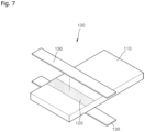
- FIGS. 7 and 8 are diagrams for describing a lead tab according to another embodiment of the present disclosure.
- a lead tab 100 includes a metal plate 110, an insulating film 130 bonded to the metal plate 110, and a plurality of concavo-convex patterns 120 formed on a surface region of the metal plate 110, to which the insulating film 130 is bonded.
- the plurality of concavo-convex patterns 120 is formed through a surface treatment of emitting laser light onto the surface region of the metal plate 110, to which the insulating film 130 is bonded.
- the concavo-convex patterns 120 are located between an end and a central region of the metal plate 110.
- the concavo-convex patterns 120 are formed in the widthwise direction of the metal plate 110, and have a stripe shape like the shape of the insulating film 130.
- the concavo-convex patterns 120 have an area equal to or smaller than the contact area between the metal plate 110 and the insulating film 130.
- the concavo-convex pattern 120 is formed in at least one pattern among a dot pattern, a line pattern, a lattice pattern, and combinations thereof, but is not limited thereto.
- the concavo-convex patterns 120 adjacent to each other have a spacing of about 0.001 mm to about 0.5 mm therebetween.
- the concavo-convex patterns 120 have an etching depth ranging from about 1% to about 80% of the total thickness of the metal plate 110.
- the area of the concavo-convex patterns 120 ranges from about 10% to about 95% of the total area of the metal plate 110.
- the concavo-convex patterns 120 include first concavo-convex patterns formed on the front surface of the metal plate 110 and second concavo-convex patterns formed on the rear surface of the metal plate 110.
- the first concavo-convex patterns are formed at the same position as the second concavo-convex patterns.
- first concavo-convex patterns and the second concavo-convex patterns face each other with the metal plate 110 interposed therebetween.
- first concavo-convex patterns formed on the front surface of the metal plate 110 are the same shape as the second concavo-convex patterns formed on the rear surface of the metal plate 110.
- the first concavo-convex patterns formed on the front surface of the metal plate 110 have a different shape from the second concavo-convex patterns formed on the rear surface of the metal plate 110.
- the spacing between the first concavo-convex patterns is different from the spacing between the second concavo-convex patterns.
- the spacing between the first concavo-convex patterns is equal to the spacing between the second concavo-convex patterns.
- the first concavo-convex pattern has a different size from the second concavo-convex pattern.
- the first concavo-convex pattern has the same size as the second concavo-convex pattern.
- the first concavo-convex patterns are arranged according to a different arrangement rule from that of the second concavo-convex patterns.
- the first concavo-convex patterns are arranged according to the same arrangement rule as that of the second concavo-convex patterns.
- the roughness value of the front surface of the metal plate 110 on which the first concavo-convex patterns are formed is different from that of the rear surface of the metal plate 110 on which the second concavo-convex patterns are formed.
- the roughness value of the front surface of the metal plate 110 on which the first concavo-convex patterns are formed is equal to that of the rear surface of the metal plate 110 on which the second concavo-convex patterns are formed.
- the area of the first concavo-convex patterns formed on the front surface of the metal plate 110 is equal to that of the second concavo-convex patterns formed on the rear surface of the metal plate 110.
- the area of the first concavo-convex patterns formed on the front surface of the metal plate 110 is different from that of the second concavo-convex patterns formed on the rear surface of the metal plate 110.
- the laser light has an output value decided on the basis of the material of the metal plate 110, and the surface of the metal plate 110 is treated with the laser light having the decided output value.
- the surface of the metal plate 110 is treated with the laser light having a first output value, when the metal plate 110 is made of a single metal, and the surface of the metal plate 110 is treated with the laser light having a second output value, when the metal plate 110 is made of a composite metal.
- the first and second output values of the laser light are equal to each other.
- the first and second output values of the laser light are different from each other.
- the second output value of the laser light is larger than the first output value of the laser light.
- the surface of the metal plate 110 is treated with the laser light having the first output value, when the metal plate 110 is made of AI, and the surface of the metal plate 110 is treated with the laser light having the second output value, when the metal plate 110 is made of NiCu.
- the second output value of the laser light is larger than the first output value of the laser light.
- the output value of the laser light is decided on the basis of preset surface roughness of the metal plate 110, and the surface of the metal plate 110 is treated with the laser light having the decided output value.
- the surface roughness of the metal plate 110 is set in advance, and the output value of the laser light is decided according to the surface roughness. Then, the laser light having the decided output value is emitted onto the surface of the metal plate 110, in order to form the concavo-convex patterns 120 on the surface of the metal plate 110 such that the metal plate 110 has the set surface roughness.
- the laser light is applied to at least one surface of the front and rear surfaces of the metal plate 110, in order to form the plurality of concavo-convex patterns 120.
- the laser light having the first output value is applied onto the front surface of the metal plate 110 so as to form first concavo-convex patterns
- the laser light having the second output value is applied onto the rear surface of the metal plate 110 so as to form second concavo-convex patterns.
- the first output value of the laser light is equal to the second output value of the laser light.
- the first output value of the laser light is different from the second output value of the laser light.
- first laser light having the first output value is emitted onto the front surface of the metal plate 110 so as to form the first concavo-convex patterns
- second laser light having the second output value is emitted onto the rear surface of the metal plate 110 so as to form the second concavo-convex patterns.
- the metal plate 110 is formed of a single metal layer, and the concavo-convex patterns 120 are formed on the surface of the single metal layer.
- the metal plate 110 is formed of an Al layer, and the concavo-convex patterns 120 are formed on the surface of the Al layer.
- the metal plate 110 is composed of a first metal layer and a second metal layer plated on the surface of the first metal layer, and the concavo-convex patterns 120 are formed on the surface of the second metal layer.
- the second metal layer includes a second metal layer plated on the top surface of the first metal layer and a second metal layer plated on the bottom surface of the first metal layer.
- the metal plate 110 is composed of a Cu layer and a Ni layer plated on the surface of the Cu layer, and the concavo-convex patterns 120 are formed on the surface of the Ni layer.
- the concavo-convex patterns 120 have a depth equal to or smaller than the thickness of the second metal layer.
- the concavo-convex patterns 120 have a depth equal to or larger than the thickness of the second metal layer.
- the concavo-convex patterns 120 of the lead tab 100 according to the present disclosure are coated with a coating solution.
- the lead tab 100 having the concavo-convex patterns 120 formed thereon is dipped into a coating solution for a predetermined time, such that the concavo-convex patterns 120 are coated with the coating solution.
- a sprayer is used to spray a coating solution onto the region where the concavo-convex patterns 120 are formed, such that the concavo-convex patterns 120 are coated with the coating solution.
- a brush is used to apply a coating solution onto the region where the concavo-convex patterns 120 are formed, such that the concavo-convex patterns 120 are coated with the coating solution.
- the lead tab 100 is dried for a predetermined time.
- the insulating film 130 is bonded onto the concavo-convex patterns 120 coated with the coating solution.
- the lead tab 100 is cut into preset sizes before the concavo-convex patterns 120 are formed.
- the lead tab 100 is cut into preset sizes, before the coating solution is applied after the concavo-convex patterns 120 are formed.
- the lead tab 100 is cut into preset sizes.
- cutting positions of the lead tab 100 are scanned and decided on the basis of the concavo-convex patterns 120, and the lead tab 100 is cut on the basis of the decided cutting positions.
- the plurality of concavo-convex patterns for increasing the surface area of the lead tab is formed by treating the surface of the lead tab, to which the insulating film is bonded or fused, with laser light, and thus improve the fusion performance between the lead tab and the insulating film without using a chemical, which makes it possible to minimize the environmental pollution and the defect rate while raising the productivity.
- the laser-etched patterns are formed on the surface of the processing area of the lead tab to which the insulating film is fused or bonded, in order to increase the surface area of the fused or bonded surface of the lead tab.
- FIG. 9 is a diagram for describing the area of the concave-convex patterns according to the present disclosure.
- the concavo-convex patterns 120 are formed only in a partial region of the metal plate 110.
- the concavo-convex patterns 120 are located between an end and a central region of the metal plate 110.
- the formation region 122 of the concavo-convex patterns 120 is formed in the widthwise direction of the metal plate 110, and have a stripe shape.
- the present disclosure is not limited thereto.
- the area of the concavo-convex patterns 120 is equal to or smaller than the contact area between the metal plate 110 and the insulating film 130.
- the width of the concavo-convex patterns 120 is equal to or smaller than the width of the insulating film 130.
- the concavo-convex patterns 120 are formed to have a larger width than the insulating film 130, the resultant structure becomes inefficient, and when the concavo-convex patterns 120 are formed to have a too small width, a surface area corresponding to the bonded or fused surface is so small that the bonding or fusion efficiency may be degraded.
- the concavo-convex patterns 120 are formed with a uniform depth in a predetermined region of the metal plate 110.
- the concavo-convex patterns 120 are formed with a depth ranging from 1% to 80% of the thickness of the metal plate 110.
- the concavo-convex patterns 120 are formed with non-uniform depths in a predetermined region of the metal plate 110.
- the concavo-convex patterns 120 formed at an edge region of the predetermined region of the metal plate 110 have a larger depth than the concavo-convex patterns 120 formed in the central region of the predetermined region of the metal plate 110.
- the concavo-convex patterns 120 are formed in the predetermined region of the metal plate 110 such that the depths of the concavo-convex patterns 120 gradually increase from the central region toward the edge region in the predetermined region.
- the concavo-convex patterns 120 are formed in the entire predetermined region of the metal plate 110.
- the concavo-convex patterns 120 are formed only in a part of the predetermined region of the metal plate 110.
- the area of the concavo-convex patterns 120 formed in the predetermined region ranges from 10% to 95% of the total area of the metal plate 110.
- the concavo-convex patterns 120 are formed in the predetermined region of the metal plate 110, and the concavo-convex patterns adjacent to each other have a uniform spacing therebetween.
- the concavo-convex patterns 120 are formed in the predetermined region of the metal plate 110, and the concavo-convex patterns adjacent to each other have a non-uniform spacing therebetween.
- the concavo-convex patterns 120 are formed in the predetermined region of the metal plate 110 such that the spacings between the concavo-convex patterns adjacent to each other gradually decrease from the central region toward the edge region in the predetermined region.
- the concavo-convex patterns 120 of the lead tab 100 according to the present disclosure are coated with a coating solution.
- the lead tab 100 having the concavo-convex patterns 120 formed thereon is dipped into a coating solution for a predetermined time, such that the concavo-convex patterns 120 are coated with the coating solution.
- a sprayer is used to spray a coating solution onto the around where the concavo-convex patterns 120 are formed, such that the concavo-convex patterns 120 are coated with the coating solution.
- a brush is used to apply a coating solution onto the around where the concavo-convex patterns 120 are formed, such that the concavo-convex patterns 120 are coated with the coating solution.
- the lead tab 100 is dried for a predetermined time, and then the insulating film 130 is bonded onto the concavo-convex patterns 120 coated with the coating solution.
- FIG. 10 is a diagram for describing a laser etching device for forming the concavo-convex patterns according to the present disclosure.
- a laser etching device is installed between a supply unit and a cutting unit so as to perform a laser etched pattern formation process on a lead tab material roll LO.
- the laser etching device is installed between the cutting unit and a loading box so as to perform a laser marking process on a lead tab.
- the laser etching device is configured to laser-mark laser etched patterns P on the top and bottom surfaces of the lead tab material roll LO.
- the laser etching device includes a first marking machine 32 for laser-marking the laser-etched patterns on the top surface of a predetermined laser etched pattern processing area of the lead tab material roll LO, and a second marking machine for laser-marking the laser etched patterns on the bottom surface of the laser etched pattern processing area of the lead tab material roll LO.
- the installation position of the first marking machine 32 is not specifically limited.
- the first marking machine 32 is installed to emit laser beam LB onto the lead tab material roll LO transferred from a feeding roller, or specifically the top surface of a predetermined laser etched pattern processing area of the lead tab material roll LO located between a first conveyer belt and a second conveyer belt.
- the installation position of the second marking machine is not specifically limited.
- the second marking machine is installed to emit laser beam LB onto the lead tab material roll LO having passed through the first marking machine 32, or specifically the bottom surface of a predetermined laser etched pattern processing area of the lead tab material roll LO located between the second conveyer belt and a third conveyer belt.
- the first marking machine 32 includes a first laser oscillator configured to generate and oscillate the laser beam LB, a first laser scanner configured to emit the laser beam LB, transferred from the first laser oscillator, onto a predetermined scan area, a first scanner driver configured to reciprocate the first laser scanner in the widthwise direction of the lead tab material roll LO, and one or more first reflecting mirrors installed between the first laser oscillator and the first laser scanner and configured to transfer the laser beam LB oscillated by the first laser oscillator to the first laser scanner.
- the second marking machine includes a second laser oscillator configured to generate and oscillate the laser beam LB, a second laser scanner configured to emit the laser beam LB, transferred from the second laser oscillator, onto the predetermined scan area, a second scanner driver configured to reciprocate the second laser scanner in the widthwise direction of the lead tab material roll LO, and one or more second reflecting mirrors installed between the second laser oscillator and the second laser scanner and configured to transfer the laser beam LB oscillated by the second laser oscillator to the second laser scanner.
- the first marking machine 32 and the second marking machine have the same structure except the locations onto which the first and second marking machines emit the laser beams LB. Thus, hereafter, the first marking machine 32 will be taken as an example for describing the structures of the marking machines.
- the first laser oscillator generates and oscillates the laser beam LB capable of laser-processing the lead tab material roll LO.
- the first laser oscillator when the lead tab material roll LO is made of synthetic resin, the first laser oscillator generates and oscillate CO 2 laser beam LB having a wavelength of 9.3 ⁇ m or 10.6 ⁇ m.
- the first laser scanner is configured to adjust an optical path of the laser beam LB transferred through the first reflecting mirror from the first laser oscillator, such that the laser beam LB can be emitted onto the predetermined scan area.
- the first laser scanner includes an X-axis mirror 32e and a Y-axis mirror 32g.
- the X-axis mirror 32e is driven by an X-axis servo motor 32f, and is configured to change the optical path of the laser beam LB in the widthwise direction
- the Y-axis mirror 32g is driven by a Y-axis servo motor 32h, and is configured to change the optical path of the laser beam LB in a longitudinal direction.
- the laser beam LB whose optical path has been changed by the X-axis mirror 32e and the Y-axis mirror 32g is concentrated by a lens 32i included in the first laser scanner, and emitted onto the lead tab material roll LO.
- the lens 32i is an f-theta ( ⁇ ) lens, but is not limited thereto.
- the laser etched pattern processing area is one area of the lead tab material roll LO, on which a surface treatment is to be performed through a laser marking process, and is set to the position to which an insulating film for sealing the interface between the lead tab and a battery case is fused.
- Such a processing area is set with a predetermined reference spacing on the lead tab material roll LO, such that each of the lead tabs divided from the lead tab material roll LO by the cutting unit includes the laser etched patterns.
- the reference spacing is not specifically limited.
- the reference spacing corresponds to a length L of the lead tab.
- the lead tab having the concavo-convex patterns according to the present disclosure is applied to a pouch-type secondary battery.
- the pouch-type secondary battery includes a battery case serving as a pouch-type exterior material, an electrode assembly housed in the battery case, a lead tab electrically connected to electrode tabs of electrodes included in the electrode assembly and extended to the outside of the battery case, and an insulating film configured to electrically insulate the lead tab.
- the insulating film has one surface fused to the lead tab and the other surface opposite to the one surface and fused to the battery case, and performs a function of sealing the interface between the lead tab and the battery case serving as a pouch-type exterior material.
- the lead tab is made of a metallic material such as aluminum (Al) or copper (Cu)
- the insulating film is made of synthetic resin such as polypropylene
- the battery case serving as a pouch-type exterior material is made of synthetic resin and includes a synthetic resin layer fused with the insulating film.
- the concavo-convex patterns of the lead tab according to the present disclosure increase the bonding and fusion area with the insulating film, thereby improving the fusion or bonding performance between the insulating film and the lead tab.
- the plurality of concavo-convex patterns for increasing the surface area of the lead tab is formed by treating the surface of the lead tab with external energy, and thus improve the fusion performance between the lead tab and the insulating film without using a chemical, which makes it possible to minimize the environmental pollution and the defect rate while raising the productivity.
- the concavo-convex patterns are formed on the surface of the processing area of the lead tab, to which the insulating film is fused or bonded, such that the surface area of the fused or bonded surface of the lead tab is increased, which makes it is possible to improve the fusion or bonding performance between the insulating film and the processing area of the lead tab.
Landscapes
- Physics & Mathematics (AREA)
- Optics & Photonics (AREA)
- Chemical & Material Sciences (AREA)
- Chemical Kinetics & Catalysis (AREA)
- Electrochemistry (AREA)
- General Chemical & Material Sciences (AREA)
- Engineering & Computer Science (AREA)
- Plasma & Fusion (AREA)
- Mechanical Engineering (AREA)
- Connection Of Batteries Or Terminals (AREA)
Description
- The present disclosure relates to a pouch-type secondary battery comprising a lead tab.
- In general, a secondary battery refers to a battery which can be repeatedly used through a discharging process of converting chemical energy into electrical energy and a charging process of converting electrical energy into chemical energy.
- Examples of the secondary battery may include a nickelcadmium (Ni-Cd) battery, a nickel-hydrogen (Ni-MH) battery, a lithium-metal battery, a lithium-ion (NLi-Ion) battery, and a lithium-ion (Li-Ion) Polymer Battery (hereafter, referred to as "LIPB").
- Among the secondary batteries, the lithium secondary battery has a cycle life of about 500 or more times and a short charging time of about one or two hours, and is lighter by about 30 to 40% than the nickel-hydrogen battery, thereby making it possible to reduce the weight of a product. Furthermore, the lithium secondary battery has excellent energy density and the highest voltage per unit battery, which ranges from 3.0 to 3.7 V, among the existing secondary batteries. Thus, the lithium secondary battery may have characteristics optimized to mobile devices.
- Such a lithium secondary battery may include an electrode assembly housed in a battery case, a lead tab electrically connected to electrode tabs of electrodes included in the electrode assembly and extended to the outside of the battery case, and an insulating film configured to electrically insulate the lead tab.
- In particular, the insulating film may have one surface fused to the lead tab and the other surface corresponding to the opposite surface of the one surface and fused to the battery case, and may perform a function of sealing the interface between the lead tab and the electrode case.
- However, since the lead tab and the insulating film are made of different materials, there is a limitation in reliably fusing the insulating film to the lead tab.
- In the related art, the surface of the lead tab has been chemically treated with a chemical, in order to improve the fusion performance between the lead tab and the insulating film.
- However, the existing surface treatment technology may cause an environmental pollution problem because a toxic substance may be contained in the chemical used to treat the surface of the lead tab. In addition, the existing surface treatment technology may require a long time to treat the surface of the lead tab, thereby reducing the productivity of the secondary battery.
- Therefore, there is a need for the development of a lead tab which can improve the fusion performance between the lead tab and an insulating film without using a chemical, and thus minimize the environmental pollution and the defect rate while raising the productivity.
-
-
Korean Patent No. 10-1586072 (registered on January 11, 2016 -
KR 10-1698564 B1 -
KR 10-2019-0078863 A - The invention is defined by the appended claims.
-
-
FIG. 1 is a diagram for describing a lead tab according to an embodiment of the present disclosure. -
FIG. 2 is a diagram for describing a lead tab according to another embodiment of the present disclosure. -
FIGS. 3A to 3C are diagrams for describing concavo-convex patterns according to the present disclosure. -
FIG. 4 is a diagram for describing the position of the concave-convex patterns according to the present disclosure. -
FIG. 5 is a diagram for describing the depth of the concavo-convex patterns formed in the lead tab ofFIG. 1 . -
FIGS. 6A and6B are diagrams for describing the depth of the concavo-convex patterns formed in the lead tab ofFIG. 2 . -
FIGS. 7 and8 are diagrams for describing a lead tab according to another embodiment of the present disclosure. -
FIG. 9 is a diagram for describing the area of the concave-convex patterns according to the present disclosure. -
FIG. 10 is a diagram for describing a laser etching device for forming the concavo-convex patterns according to the present disclosure. - Hereafter, the present disclosure will be described in more detail with reference to the drawings.
- Terms such as "module" and "unit" for components used in the following descriptions are simply given in consideration of the ease of writing this specification, and the "module" and the "unit" may be interchangeably used.
- In this specification, general terms which are widely used at the moment are selected as the terms used herein in consideration of functions in the present disclosure.
-
FIG. 1 is a diagram for describing a lead tab according to an embodiment of the present disclosure, andFIG. 2 is a diagram for describing a lead tab according to another embodiment of the present disclosure. -
FIG. 1 illustrates the lead tab for a positive electrode, andFIG. 2 illustrates the lead tab for a negative electrode. - As illustrated in
FIGS. 1 and2 , alead tab 100 according to the present disclosure includes ametal plate 110 and a plurality of concavo-convex patterns 120 formed on the surface of themetal plate 110. - The plurality of concavo-
convex patterns 120 is formed through a surface treatment of applying predetermined external energy onto the surface of themetal plate 110. - The external energy is laser light energy.
- Furthermore, the external energy has an output value decided on the basis of the material of the
metal plate 110, and the surface of themetal plate 110 is treated with the external energy having the decided output value. - That is, the surface of the
metal plate 110 is treated with the external energy having a first output value, when themetal plate 110 is made of a single metal, and the surface of themetal plate 110 is treated with the external energy having a second output value, when themetal plate 110 is made of a composite metal. - The first and second output values of the external energy are equal to each other.
- In some cases, the first and second output values of the external energy are different from each other.
- At this time, the second output value of the external energy is larger than the first output value of the external energy.
- For example, the surface of the
metal plate 110 is treated with the external energy having the first output value, when themetal plate 110 is made of a single metal of aluminum (AI), and the surface of themetal plate 110 is treated with the external energy having the second output value, when themetal plate 110 is made of a composite metal of nickel and copper (NiCu). - In this case, the second output value of the external energy is larger than the first output value of the external energy.
- The output value of the external energy is decided on the basis of preset surface roughness of the
metal plate 110, and the surface of themetal plate 110 is treated with the external energy having the decided output value. - For example, the surface roughness of the
metal plate 110 is set in advance, and the output value of the external energy is decided according to the surface roughness. Then, the external energy having the decided output value is emitted onto the surface of themetal plate 110, in order to form the concavo-convex patterns 120 on the surface of themetal plate 110 such that themetal plate 110 has the set surface roughness. - The external energy is applied to at least one surface of the front and rear surfaces of the
metal plate 110, in order to form the plurality of concavo-convex patterns 120. - At this time, the external energy having the first output value is applied onto the front surface of the
metal plate 110 so as to form first concavo-convex patterns 120a, and the external energy having the second output value is applied onto the rear surface of themetal plate 110 so as to form second concavo-convex patterns 120b. - In this case, the first output value of the external energy is equal to the second output value of the external energy.
- In some cases, the first output value of the external energy is different from the second output value of the external energy.
- For example, according to the present disclosure, first laser light having the first output value is emitted onto the front surface of the
metal plate 110 so as to form the first concavo-convex patterns 120a, and second laser light having the second output value is emitted onto the rear surface of themetal plate 110 so as to form the second concavo-convex patterns 120b. - Furthermore, the first concavo-
convex patterns 120a formed on the front surface of themetal plate 110 are the same as the second concavo-convex patterns 120b formed on the rear surface of themetal plate 110. - In some cases, the first concavo-
convex patterns 120a formed on the front surface of themetal plate 110 are different from the second concavo-convex patterns 120b formed on the rear surface of themetal plate 110. - Furthermore, the spacing between the first concavo-
convex patterns 120a is different from the spacing between the second concavo-convex patterns 120b. - In some cases, the spacing between the first concavo-
convex patterns 120a is equal to the spacing between the second concavo-convex patterns 120b. - Furthermore, the size of the first concavo-
convex pattern 120a is different from the size of the second concavo-convex pattern 120b. - In some cases, the size of the first concavo-
convex pattern 120a is equal to the size of the second concavo-convex pattern 120b. - Furthermore, the first concavo-
convex patterns 120a are arranged according to a different arrangement rule from that of the second concavo-convex patterns 120b. - In some cases, the first concavo-
convex patterns 120a are arranged according to the same arrangement rule as that of the second concavo-convex patterns 120b. - Furthermore, the roughness value of the front surface of the
metal plate 110 on which the first concavo-convex patterns 120a are formed is different from that of the rear surface of themetal plate 110 on which the second concavo-convex patterns 120b are formed. - In some cases, the roughness value of the front surface of the
metal plate 110 on which the first concavo-convex patterns 120a are formed is equal to the roughness value of the rear surface of themetal plate 110 on which the second concavo-convex patterns 120b are formed. - The concavo-
convex pattern 120 includes at least one pattern among a dot pattern, a line pattern, a lattice pattern, and combinations thereof, but is not limited thereto. - The concavo-
convex patterns 120 adjacent to each other has a spacing of about 0.001 mm to about 0.5 mm therebetween. - The concavo-
convex patterns 120 have an etching depth ranging from about 1% to about 80% of the total thickness of themetal plate 110. - Furthermore, the area of the concavo-
convex patterns 120 range from about 10% to about 95% of the total area of themetal plate 110. - The concavo-
convex patterns 120 are formed only in a partial region of themetal plate 110. - In this case, the concavo-
convex patterns 120 are located between an end and a central region of themetal plate 110. - For example, the concavo-
convex patterns 120 are formed in the widthwise direction of themetal plate 110, and have a stripe shape. - As illustrated in
FIG. 1 , themetal plate 110 of thelead tab 100 for a positive electrode is formed of a single metal layer, and the concavo-convex patterns 120 are formed on the surface of the single metal layer. - For example, the
metal plate 110 is formed of an Al layer, and the concavo-convex patterns 120 are formed on the surface of the Al layer. - Furthermore, as illustrated in
FIG. 2 , themetal plate 110 of thelead tab 100 for a negative electrode is composed of afirst metal layer 112 and asecond metal layer 114 plated on the surface of thefirst metal layer 112, and the concavo-convex patterns 120 is formed on the surface of thesecond metal layer 114. - The
second metal layer 114 includes asecond metal layer 114a plated on the top surface of thefirst metal layer 112 and asecond metal layer 114b plated on the bottom surface of thefirst metal layer 112. - For example, the
metal plate 110 is composed of a Cu layer and a Ni layer plated on the surface of the Cu layer, and the concavo-convex patterns 120 are formed on the surface of the Ni layer. - The concavo-
convex pattern 120 has a depth equal to or smaller than the thickness of thesecond metal layer 114. - In some cases, the concavo-
convex pattern 120 has a depth equal to or larger than the thickness of thesecond metal layer 114. - According to the present disclosure, the plurality of concavo-convex patterns for increasing the surface area of the lead tab is formed by treating the surface of the lead tab with external energy, and thus improve the fusion performance between the lead tab and the insulating film without using a chemical, which makes it possible to minimize the environmental pollution and the defect rate while raising the productivity.
- Furthermore, the concavo-convex patterns are formed on the surface of the processing area of the lead tab, to which the insulating film is fused or bonded, such that the surface area of the fused or bonded surface of the lead tab is increased, which makes it is possible to improve the fusion or bonding performance between the insulating film and the processing area of the lead tab.
- Furthermore, when the insulating films are fused or bonded, bubbles formed at the interfaces between the insulating films and the processing area of the lead tab are discharged to the outside through the concavo-convex patterns, which makes it possible to prevent the bubbles from being contained in the interfaces.
-
FIGS. 3A to 3C are diagrams for describing concavo-convex patterns according to the present disclosure. - As illustrated in
FIGS. 3A to 3C , the lead tab according to the present disclosure has the plurality of concavo-convex patterns 120 formed on the surface of themetal plate 110. - The plurality of concavo-
convex patterns 120 is formed through a surface treatment of applying predetermined external energy such as laser light onto the surface of themetal plate 110. - As illustrated in
FIG. 3A , the concavo-convex patterns 120 are formed as line patterns or formed as lattice patterns as illustrated inFIG. 3B , or formed as dot patterns as illustrated inFIG. 3C . - In some cases, the concavo-
convex patterns 120 are formed as a pattern combination including dot patterns, line patterns, and lattice patterns. - The spacing between the concavo-
convex patterns 120 adjacent to each other ranges from about 0.001 mm to about 0.5 mm, the etching depth of the concavo-convex patterns 120 ranges from about 1% to about 80% of the total thickness of themetal plate 110, and the area of the concavo-convex patterns 120 ranges from about 10% to about 95% of the total area of themetal plate 110. However, the present disclosure is not limited thereto. -
FIG. 4 is a diagram for describing the position of the concave-convex patterns according to the present disclosure. - As illustrated in
FIG. 4 , the concavo-convex patterns 120 are formed only in a partial region of themetal plate 110. - In this case, the concavo-
convex patterns 120 are located between an end and a central region of themetal plate 110. - For example, the
formation region 122 of the concavo-convex patterns 120 is formed in the widthwise direction of themetal plate 110, and have a stripe shape. However, the present disclosure is not limited thereto. - Furthermore, the concavo-
convex patterns 120 are formed with a uniform depth in a predetermined region of themetal plate 110. - For example, the concavo-
convex patterns 120 are formed with a depth ranging from 1% to 80% of the thickness of themetal plate 110. - In some cases, the concavo-
convex patterns 120 are formed with non-uniform depths in a predetermined region of themetal plate 110. - In this case, the concavo-
convex patterns 120 formed in an edge region of the predetermined region of themetal plate 110 have a larger depth than the concavo-convex patterns 120 formed in the central region of the predetermined region of themetal plate 110. - In a different case, the depths of the concavo-
convex patterns 120 gradually increase from the central region toward the edge region in the predetermined region. - Furthermore, the concavo-
convex patterns 120 are formed in the entire predetermined region of themetal plate 110. - In some cases, the concavo-
convex patterns 120 are formed only in a part of the predetermined region of themetal plate 110. - For example, the area of the concavo-convex patterns ranges from 10% to 95% of the total area in the predetermined region of the
metal plate 110. - Furthermore, the concavo-
convex patterns 120 are formed in plurality in the predetermined region of themetal plate 110, and the concavo-convex patterns adjacent to each other have a uniform spacing distance therebetween. - In some cases, the concavo-
convex patterns 120 are formed in plurality in the predetermined region of themetal plate 110, and the concavo-convex patterns adjacent to each other have a non-uniform spacing distance therebetween. - At this time, the spacings between the concavo-convex patterns adjacent to each other gradually decrease from the central region toward the edge region in the predetermined region.
-
FIG. 5 is a diagram for describing the depth of the concavo-convex patterns formed in the lead tab ofFIG. 1 . - As illustrated in
FIG. 5 , themetal plate 110 of the lead tab for a positive electrode is formed of a single metal layer, and the concavo-convex patterns 120 are formed on the surface of the single metal layer. - For example, the
metal plate 110 is formed of an Al layer, and the concavo-convex patterns 120 are formed on the surface of the Al layer. - The concavo-
convex patterns 120 have an etching depth d1 ranging from about 1% to about 80% of the total thickness of themetal plate 110, but is not limited thereto. -
FIGS. 6A and6B are diagrams for describing the depth of the concavo-convex patterns formed in the lead tab ofFIG. 2 . - As illustrated in
FIGS. 6A and6B , themetal plate 110 of the lead tab for a negative electrode is composed of thefirst metal layer 112 and thesecond metal layer 114 plated on thefirst metal layer 112, and the concavo-convex patterns 120 are formed on the surface of thesecond metal layer 114. - For example, the
metal plate 110 is composed of a Cu layer and a Ni layer plated on the surface of the Cu layer, and the concavo-convex patterns 120 are formed on the surface of the Ni layer. - As illustrated in
FIG. 6A , the concavo-convex patterns 120 have a depth d2 equal to or smaller than the thickness of thesecond metal layer 114. - In some cases, as illustrated in
FIG. 6B , the concavo-convex patterns 120 have a depth d3 equal to or larger than the thickness of thesecond metal layer 114. -
FIGS. 7 and8 are diagrams for describing a lead tab according to another embodiment of the present disclosure. - As illustrated in
FIGS. 7 and8 , alead tab 100 according to the present disclosure includes ametal plate 110, an insulatingfilm 130 bonded to themetal plate 110, and a plurality of concavo-convex patterns 120 formed on a surface region of themetal plate 110, to which the insulatingfilm 130 is bonded. - The plurality of concavo-
convex patterns 120 is formed through a surface treatment of emitting laser light onto the surface region of themetal plate 110, to which the insulatingfilm 130 is bonded. - The concavo-
convex patterns 120 are located between an end and a central region of themetal plate 110. - Furthermore, the concavo-
convex patterns 120 are formed in the widthwise direction of themetal plate 110, and have a stripe shape like the shape of the insulatingfilm 130. - The concavo-
convex patterns 120 have an area equal to or smaller than the contact area between themetal plate 110 and the insulatingfilm 130. - The concavo-
convex pattern 120 is formed in at least one pattern among a dot pattern, a line pattern, a lattice pattern, and combinations thereof, but is not limited thereto. - The concavo-
convex patterns 120 adjacent to each other have a spacing of about 0.001 mm to about 0.5 mm therebetween. - The concavo-
convex patterns 120 have an etching depth ranging from about 1% to about 80% of the total thickness of themetal plate 110. - Furthermore, the area of the concavo-
convex patterns 120 ranges from about 10% to about 95% of the total area of themetal plate 110. - The concavo-
convex patterns 120 include first concavo-convex patterns formed on the front surface of themetal plate 110 and second concavo-convex patterns formed on the rear surface of themetal plate 110. - The first concavo-convex patterns are formed at the same position as the second concavo-convex patterns.
- Furthermore, the first concavo-convex patterns and the second concavo-convex patterns face each other with the
metal plate 110 interposed therebetween. - In addition, the first concavo-convex patterns formed on the front surface of the
metal plate 110 are the same shape as the second concavo-convex patterns formed on the rear surface of themetal plate 110. - In some cases, the first concavo-convex patterns formed on the front surface of the
metal plate 110 have a different shape from the second concavo-convex patterns formed on the rear surface of themetal plate 110. - The spacing between the first concavo-convex patterns is different from the spacing between the second concavo-convex patterns.
- In some cases, the spacing between the first concavo-convex patterns is equal to the spacing between the second concavo-convex patterns.
- Furthermore, the first concavo-convex pattern has a different size from the second concavo-convex pattern.
- In some cases, the first concavo-convex pattern has the same size as the second concavo-convex pattern.
- Furthermore, the first concavo-convex patterns are arranged according to a different arrangement rule from that of the second concavo-convex patterns.
- In some cases, the first concavo-convex patterns are arranged according to the same arrangement rule as that of the second concavo-convex patterns.
- Furthermore, the roughness value of the front surface of the
metal plate 110 on which the first concavo-convex patterns are formed is different from that of the rear surface of themetal plate 110 on which the second concavo-convex patterns are formed. - In some cases, the roughness value of the front surface of the
metal plate 110 on which the first concavo-convex patterns are formed is equal to that of the rear surface of themetal plate 110 on which the second concavo-convex patterns are formed. - The area of the first concavo-convex patterns formed on the front surface of the
metal plate 110 is equal to that of the second concavo-convex patterns formed on the rear surface of themetal plate 110. - In some cases, the area of the first concavo-convex patterns formed on the front surface of the
metal plate 110 is different from that of the second concavo-convex patterns formed on the rear surface of themetal plate 110. - The laser light has an output value decided on the basis of the material of the
metal plate 110, and the surface of themetal plate 110 is treated with the laser light having the decided output value. - That is, the surface of the
metal plate 110 is treated with the laser light having a first output value, when themetal plate 110 is made of a single metal, and the surface of themetal plate 110 is treated with the laser light having a second output value, when themetal plate 110 is made of a composite metal. - In this case, the first and second output values of the laser light are equal to each other.
- In some cases, the first and second output values of the laser light are different from each other.
- At this time, the second output value of the laser light is larger than the first output value of the laser light.
- For example, the surface of the
metal plate 110 is treated with the laser light having the first output value, when themetal plate 110 is made of AI, and the surface of themetal plate 110 is treated with the laser light having the second output value, when themetal plate 110 is made of NiCu. - In this case, the second output value of the laser light is larger than the first output value of the laser light.
- The output value of the laser light is decided on the basis of preset surface roughness of the
metal plate 110, and the surface of themetal plate 110 is treated with the laser light having the decided output value. - For example, the surface roughness of the
metal plate 110 is set in advance, and the output value of the laser light is decided according to the surface roughness. Then, the laser light having the decided output value is emitted onto the surface of themetal plate 110, in order to form the concavo-convex patterns 120 on the surface of themetal plate 110 such that themetal plate 110 has the set surface roughness. - The laser light is applied to at least one surface of the front and rear surfaces of the
metal plate 110, in order to form the plurality of concavo-convex patterns 120. - At this time, the laser light having the first output value is applied onto the front surface of the
metal plate 110 so as to form first concavo-convex patterns, and the laser light having the second output value is applied onto the rear surface of themetal plate 110 so as to form second concavo-convex patterns. - In this case, the first output value of the laser light is equal to the second output value of the laser light.
- In some cases, the first output value of the laser light is different from the second output value of the laser light.
- For example, according to the present disclosure, first laser light having the first output value is emitted onto the front surface of the
metal plate 110 so as to form the first concavo-convex patterns, and second laser light having the second output value is emitted onto the rear surface of themetal plate 110 so as to form the second concavo-convex patterns. - When the
lead tab 100 according to the present disclosure is applied to a positive electrode, themetal plate 110 is formed of a single metal layer, and the concavo-convex patterns 120 are formed on the surface of the single metal layer. - For example, the
metal plate 110 is formed of an Al layer, and the concavo-convex patterns 120 are formed on the surface of the Al layer. - When the lead tab according to the present disclosure is applied to a negative electrode, the
metal plate 110 is composed of a first metal layer and a second metal layer plated on the surface of the first metal layer, and the concavo-convex patterns 120 are formed on the surface of the second metal layer. - The second metal layer includes a second metal layer plated on the top surface of the first metal layer and a second metal layer plated on the bottom surface of the first metal layer.
- For example, the
metal plate 110 is composed of a Cu layer and a Ni layer plated on the surface of the Cu layer, and the concavo-convex patterns 120 are formed on the surface of the Ni layer. - The concavo-
convex patterns 120 have a depth equal to or smaller than the thickness of the second metal layer. - In some cases, the concavo-
convex patterns 120 have a depth equal to or larger than the thickness of the second metal layer. - The concavo-
convex patterns 120 of thelead tab 100 according to the present disclosure are coated with a coating solution. - In an example not falling within the scope of the invention, the
lead tab 100 having the concavo-convex patterns 120 formed thereon is dipped into a coating solution for a predetermined time, such that the concavo-convex patterns 120 are coated with the coating solution. - In another example not falling within the scope of the invention, a sprayer is used to spray a coating solution onto the region where the concavo-
convex patterns 120 are formed, such that the concavo-convex patterns 120 are coated with the coating solution. - In still another example not falling within the scope of the invention, a brush is used to apply a coating solution onto the region where the concavo-
convex patterns 120 are formed, such that the concavo-convex patterns 120 are coated with the coating solution. - After the concavo-
convex patterns 120 are coated with the coating solution, thelead tab 100 is dried for a predetermined time. - Then, the insulating
film 130 is bonded onto the concavo-convex patterns 120 coated with the coating solution. - According to the present disclosure, the
lead tab 100 is cut into preset sizes before the concavo-convex patterns 120 are formed. - In some cases, the
lead tab 100 is cut into preset sizes, before the coating solution is applied after the concavo-convex patterns 120 are formed. - In a different case, when the concavo-
convex patterns 120 are coated with the coating solution, thelead tab 100 is cut into preset sizes. - In this case, when the
lead tab 100 is cut into the preset sizes, cutting positions of thelead tab 100 are scanned and decided on the basis of the concavo-convex patterns 120, and thelead tab 100 is cut on the basis of the decided cutting positions. - According to the present disclosure, the plurality of concavo-convex patterns for increasing the surface area of the lead tab is formed by treating the surface of the lead tab, to which the insulating film is bonded or fused, with laser light, and thus improve the fusion performance between the lead tab and the insulating film without using a chemical, which makes it possible to minimize the environmental pollution and the defect rate while raising the productivity.
- Furthermore, the laser-etched patterns are formed on the surface of the processing area of the lead tab to which the insulating film is fused or bonded, in order to increase the surface area of the fused or bonded surface of the lead tab. Thus, it is possible to improve the fusion or bonding performance between the insulating film and the processing region of the lead tab.
- Furthermore, when the insulating films are fused or bonded, bubbles generated at the interfaces between the insulating films and the processing area of the lead tab are discharged to the outside through the laser-etched patterns, which makes it possible to prevent the bubbles from being contained in the interfaces.
-
FIG. 9 is a diagram for describing the area of the concave-convex patterns according to the present disclosure. - As illustrated in
FIG. 9 , the concavo-convex patterns 120 are formed only in a partial region of themetal plate 110. - In this case, the concavo-
convex patterns 120 are located between an end and a central region of themetal plate 110. - For example, the
formation region 122 of the concavo-convex patterns 120 is formed in the widthwise direction of themetal plate 110, and have a stripe shape. However, the present disclosure is not limited thereto. - Furthermore, the area of the concavo-
convex patterns 120 is equal to or smaller than the contact area between themetal plate 110 and the insulatingfilm 130. - That is, the width of the concavo-
convex patterns 120 is equal to or smaller than the width of the insulatingfilm 130. - That is because, when the concavo-
convex patterns 120 are formed to have a larger width than the insulatingfilm 130, the resultant structure becomes inefficient, and when the concavo-convex patterns 120 are formed to have a too small width, a surface area corresponding to the bonded or fused surface is so small that the bonding or fusion efficiency may be degraded. - Furthermore, the concavo-
convex patterns 120 are formed with a uniform depth in a predetermined region of themetal plate 110. - For example, the concavo-
convex patterns 120 are formed with a depth ranging from 1% to 80% of the thickness of themetal plate 110. - In some cases, the concavo-
convex patterns 120 are formed with non-uniform depths in a predetermined region of themetal plate 110. - In this case, the concavo-
convex patterns 120 formed at an edge region of the predetermined region of themetal plate 110 have a larger depth than the concavo-convex patterns 120 formed in the central region of the predetermined region of themetal plate 110. - In a different case, the concavo-
convex patterns 120 are formed in the predetermined region of themetal plate 110 such that the depths of the concavo-convex patterns 120 gradually increase from the central region toward the edge region in the predetermined region. - Furthermore, the concavo-
convex patterns 120 are formed in the entire predetermined region of themetal plate 110. - In some cases, the concavo-
convex patterns 120 are formed only in a part of the predetermined region of themetal plate 110. - For example, the area of the concavo-
convex patterns 120 formed in the predetermined region ranges from 10% to 95% of the total area of themetal plate 110. - Furthermore, the concavo-
convex patterns 120 are formed in the predetermined region of themetal plate 110, and the concavo-convex patterns adjacent to each other have a uniform spacing therebetween. - In some cases, the concavo-
convex patterns 120 are formed in the predetermined region of themetal plate 110, and the concavo-convex patterns adjacent to each other have a non-uniform spacing therebetween. - At this time, the concavo-
convex patterns 120 are formed in the predetermined region of themetal plate 110 such that the spacings between the concavo-convex patterns adjacent to each other gradually decrease from the central region toward the edge region in the predetermined region. - The concavo-
convex patterns 120 of thelead tab 100 according to the present disclosure are coated with a coating solution. - In an example not falling within the scope of the invention, the
lead tab 100 having the concavo-convex patterns 120 formed thereon is dipped into a coating solution for a predetermined time, such that the concavo-convex patterns 120 are coated with the coating solution. - In another example not falling within the scope of the invention, a sprayer is used to spray a coating solution onto the around where the concavo-
convex patterns 120 are formed, such that the concavo-convex patterns 120 are coated with the coating solution. - In still another example not falling within the scope of the invention, a brush is used to apply a coating solution onto the around where the concavo-
convex patterns 120 are formed, such that the concavo-convex patterns 120 are coated with the coating solution. - Furthermore, when the concavo-
convex patterns 120 of thelead tab 100 are coated with the coating solution, thelead tab 100 is dried for a predetermined time, and then the insulatingfilm 130 is bonded onto the concavo-convex patterns 120 coated with the coating solution. -
FIG. 10 is a diagram for describing a laser etching device for forming the concavo-convex patterns according to the present disclosure. - A laser etching device is installed between a supply unit and a cutting unit so as to perform a laser etched pattern formation process on a lead tab material roll LO.
- In some cases, the laser etching device is installed between the cutting unit and a loading box so as to perform a laser marking process on a lead tab.
- The laser etching device is configured to laser-mark laser etched patterns P on the top and bottom surfaces of the lead tab material roll LO.
- For example, the laser etching device includes a
first marking machine 32 for laser-marking the laser-etched patterns on the top surface of a predetermined laser etched pattern processing area of the lead tab material roll LO, and a second marking machine for laser-marking the laser etched patterns on the bottom surface of the laser etched pattern processing area of the lead tab material roll LO. - The installation position of the
first marking machine 32 is not specifically limited. For example, thefirst marking machine 32 is installed to emit laser beam LB onto the lead tab material roll LO transferred from a feeding roller, or specifically the top surface of a predetermined laser etched pattern processing area of the lead tab material roll LO located between a first conveyer belt and a second conveyer belt. - The installation position of the second marking machine is not specifically limited. For example, the second marking machine is installed to emit laser beam LB onto the lead tab material roll LO having passed through the
first marking machine 32, or specifically the bottom surface of a predetermined laser etched pattern processing area of the lead tab material roll LO located between the second conveyer belt and a third conveyer belt. - The
first marking machine 32 includes a first laser oscillator configured to generate and oscillate the laser beam LB, a first laser scanner configured to emit the laser beam LB, transferred from the first laser oscillator, onto a predetermined scan area, a first scanner driver configured to reciprocate the first laser scanner in the widthwise direction of the lead tab material roll LO, and one or more first reflecting mirrors installed between the first laser oscillator and the first laser scanner and configured to transfer the laser beam LB oscillated by the first laser oscillator to the first laser scanner. - The second marking machine includes a second laser oscillator configured to generate and oscillate the laser beam LB, a second laser scanner configured to emit the laser beam LB, transferred from the second laser oscillator, onto the predetermined scan area, a second scanner driver configured to reciprocate the second laser scanner in the widthwise direction of the lead tab material roll LO, and one or more second reflecting mirrors installed between the second laser oscillator and the second laser scanner and configured to transfer the laser beam LB oscillated by the second laser oscillator to the second laser scanner.
- The
first marking machine 32 and the second marking machine have the same structure except the locations onto which the first and second marking machines emit the laser beams LB. Thus, hereafter, thefirst marking machine 32 will be taken as an example for describing the structures of the marking machines. - The first laser oscillator generates and oscillates the laser beam LB capable of laser-processing the lead tab material roll LO. For example, when the lead tab material roll LO is made of synthetic resin, the first laser oscillator generates and oscillate CO2 laser beam LB having a wavelength of 9.3 µm or 10.6 µm.
- The first laser scanner is configured to adjust an optical path of the laser beam LB transferred through the first reflecting mirror from the first laser oscillator, such that the laser beam LB can be emitted onto the predetermined scan area. For example, as illustrated in
FIG. 10 , the first laser scanner includes an X-axis mirror 32e and a Y-axis mirror 32g. The X-axis mirror 32e is driven by anX-axis servo motor 32f, and is configured to change the optical path of the laser beam LB in the widthwise direction, and the Y-axis mirror 32g is driven by a Y-axis servo motor 32h, and is configured to change the optical path of the laser beam LB in a longitudinal direction. The laser beam LB whose optical path has been changed by the X-axis mirror 32e and the Y-axis mirror 32g is concentrated by a lens 32i included in the first laser scanner, and emitted onto the lead tab material roll LO. The lens 32i is an f-theta (θ) lens, but is not limited thereto. - The laser etched pattern processing area is one area of the lead tab material roll LO, on which a surface treatment is to be performed through a laser marking process, and is set to the position to which an insulating film for sealing the interface between the lead tab and a battery case is fused. Such a processing area is set with a predetermined reference spacing on the lead tab material roll LO, such that each of the lead tabs divided from the lead tab material roll LO by the cutting unit includes the laser etched patterns. The reference spacing is not specifically limited. For example, the reference spacing corresponds to a length L of the lead tab.
- The lead tab having the concavo-convex patterns according to the present disclosure is applied to a pouch-type secondary battery.
- The pouch-type secondary battery includes a battery case serving as a pouch-type exterior material, an electrode assembly housed in the battery case, a lead tab electrically connected to electrode tabs of electrodes included in the electrode assembly and extended to the outside of the battery case, and an insulating film configured to electrically insulate the lead tab.
- In particular, the insulating film has one surface fused to the lead tab and the other surface opposite to the one surface and fused to the battery case, and performs a function of sealing the interface between the lead tab and the battery case serving as a pouch-type exterior material.
- The lead tab is made of a metallic material such as aluminum (Al) or copper (Cu), the insulating film is made of synthetic resin such as polypropylene, and the battery case serving as a pouch-type exterior material is made of synthetic resin and includes a synthetic resin layer fused with the insulating film.
- Therefore, the concavo-convex patterns of the lead tab according to the present disclosure increase the bonding and fusion area with the insulating film, thereby improving the fusion or bonding performance between the insulating film and the lead tab.
- According to the present disclosure, the plurality of concavo-convex patterns for increasing the surface area of the lead tab is formed by treating the surface of the lead tab with external energy, and thus improve the fusion performance between the lead tab and the insulating film without using a chemical, which makes it possible to minimize the environmental pollution and the defect rate while raising the productivity.
- Furthermore, the concavo-convex patterns are formed on the surface of the processing area of the lead tab, to which the insulating film is fused or bonded, such that the surface area of the fused or bonded surface of the lead tab is increased, which makes it is possible to improve the fusion or bonding performance between the insulating film and the processing area of the lead tab.
- Furthermore, when the insulating films are fused or bonded, bubbles formed at the interfaces between the insulating films and the processing area of the lead tab are discharged to the outside through the concavo-convex patterns, which makes it possible to prevent the bubbles from being contained in the interfaces.
Claims (3)
- A pouch-type secondary battery comprising a lead tab (100), wherein the lead tab (100) comprises:a metal plate (110);a plurality of concavo-convex patterns (120) formed on a surface of the metal plate (110) between an end and a central region of the metal plate (110); andan insulating film (130) bonded to the surface of the metal plate (110), on which the plurality of concavo-convex patterns (120) is located,wherein the plurality of concavo-convex patterns (120) are formed through a surface treatment of applying predetermined laser light energy onto the surface of the metal plate (110), and comprise first concavo-convex patterns (120a) formed by applying the laser light energy having a first output value onto a first area of the front surface of the metal plate (110), and second concavo-convex patterns (120b) formed by applying the laser light energy having a second output value onto a second area of the rear surface of the metal plate (110),wherein the first and second concavo-convex patterns (120a, 120b) are formed so that the concavo-convex patterns (120) adjacent to each other have a spacing of 0.001 mm to 0.5 mm, and the spacings between the concavo-convex patterns (120) adjacent to each other gradually decrease from a central region toward either edge region in a predetermined region of the metal plate (110), while the depths of the concavo-convex patterns (120) gradually increase from the central region toward the either edge region in the predetermined region of the metal plate (110),an area occupied by the concavo-convex patterns (120) ranges from 10% to 95% of the entire area of the metal plate (110),the concavo-convex patterns (120) are formed with a depth ranging from 1% to 80% of the thickness of the metal plate (110),an area occupied by the first concavo-convex patterns (120a) formed on the first area of the front surface of the metal plate (110) is different from an area occupied by the second concavo-convex patterns (120b) formed on the second area of the rear surface of the metal plate (110), andan spacing between the first concavo-convex pattern is different from an spacing between the second concavo-convex pattern.
- The pouch-type secondary battery of claim 1, wherein the first output value of the laser light energy is different than the second output value.
- The pouch-type secondary battery of claim 1, wherein the metal plate (110) of the lead tab is composed of a first metal layer (112) and a second metal layer (114, 114a, 114b) plated on the surface of the first metal layer 112, and the concavo-convex patterns (120) are formed on the surface of the second metal layer (114, 114a, 114b), when the lead tab is adapted to be applied to a negative electrode.
Applications Claiming Priority (1)
| Application Number | Priority Date | Filing Date | Title |
|---|---|---|---|
| KR1020210053524A KR102372492B1 (en) | 2021-01-11 | 2021-04-26 | Lead tab for secondary battery |
Publications (2)
| Publication Number | Publication Date |
|---|---|
| EP4084209A1 EP4084209A1 (en) | 2022-11-02 |
| EP4084209B1 true EP4084209B1 (en) | 2024-10-09 |
Family
ID=77682404
Family Applications (1)
| Application Number | Title | Priority Date | Filing Date |
|---|---|---|---|
| EP22169759.2A Active EP4084209B1 (en) | 2021-04-26 | 2022-04-25 | Lead tab for secondary battery |
Country Status (4)
| Country | Link |
|---|---|
| US (1) | US12132229B2 (en) |
| EP (1) | EP4084209B1 (en) |
| KR (1) | KR20220147011A (en) |
| CN (1) | CN113410587A (en) |
Families Citing this family (4)
| Publication number | Priority date | Publication date | Assignee | Title |
|---|---|---|---|---|
| CA3240095A1 (en) * | 2021-11-29 | 2023-06-01 | Laserax Inc. | Battery assembly and method for assembling a battery assembly |
| WO2023210587A1 (en) * | 2022-04-28 | 2023-11-02 | 株式会社エンビジョンAescジャパン | Battery cell and battery module |
| GB2631777A (en) * | 2023-07-14 | 2025-01-15 | Avocet Battery Mat Limited | Method of producing battery cell tabs with improved adhesion capability |
| DE102024206895A1 (en) * | 2024-07-23 | 2026-01-29 | Powerco Se | Method for producing a recess |
Family Cites Families (12)
| Publication number | Priority date | Publication date | Assignee | Title |
|---|---|---|---|---|
| KR100599749B1 (en) * | 2004-06-23 | 2006-07-12 | 삼성에스디아이 주식회사 | Secondary Battery and Electrode Assembly Used in the Same |
| EP1844508B1 (en) * | 2005-01-21 | 2018-08-22 | LG Chem, Ltd. | Secondary battery of excellent sealability |
| TW200721583A (en) * | 2005-08-05 | 2007-06-01 | Mitsubishi Pencil Co | Separator for fuel battery and process for producing the same |
| WO2013039298A1 (en) * | 2011-09-16 | 2013-03-21 | 주식회사 엘지화학 | Secondary battery component, manufacturing method thereof, secondary battery manufactured using component, and assembled secondary battery device |
| JP6006104B2 (en) * | 2012-02-29 | 2016-10-12 | 昭和電工パッケージング株式会社 | Tab lead manufacturing method |
| KR101968642B1 (en) * | 2012-04-23 | 2019-04-12 | 삼성전자주식회사 | Three dimensional shaped battery |
| DE112012006588T5 (en) * | 2012-06-28 | 2015-04-02 | Toyota Jidosha Kabushiki Kaisha | Method for producing a battery and a battery |
| KR101586072B1 (en) | 2014-04-07 | 2016-01-19 | 한국과학기술연구원 | Surface treatment apparatus for lead terminal of secondary battery |
| KR101698564B1 (en) * | 2016-05-02 | 2017-01-23 | 주식회사 티피에스 | An electrode terminal for secondary battery and manufacturing method thereof |
| CN108134042B (en) * | 2017-12-07 | 2020-03-17 | 赣州市中金高能电池材料股份有限公司 | Production process of high-sealing liquid-leakage-proof lithium ion battery tab |
| KR20190078863A (en) * | 2017-12-27 | 2019-07-05 | 주식회사 폴 | Lead Tab for cathode of secondary batteries, method for manufacturing the same and secondary battery having the same |
| KR20200143952A (en) * | 2019-06-17 | 2020-12-28 | 주식회사 리베스트 | Electrochemical cell and case provided therein |
-
2021
- 2021-06-22 CN CN202110691530.5A patent/CN113410587A/en active Pending
-
2022
- 2022-03-03 KR KR1020220027244A patent/KR20220147011A/en not_active Withdrawn
- 2022-04-25 EP EP22169759.2A patent/EP4084209B1/en active Active
- 2022-04-25 US US17/728,237 patent/US12132229B2/en active Active
Also Published As
| Publication number | Publication date |
|---|---|
| CN113410587A (en) | 2021-09-17 |
| KR20220147011A (en) | 2022-11-02 |
| US12132229B2 (en) | 2024-10-29 |
| EP4084209A1 (en) | 2022-11-02 |
| US20220344786A1 (en) | 2022-10-27 |
Similar Documents
| Publication | Publication Date | Title |
|---|---|---|
| EP4084209B1 (en) | Lead tab for secondary battery | |
| EP4084210B1 (en) | Method for fabricating lead tab for secondary battery | |
| KR102372492B1 (en) | Lead tab for secondary battery | |
| US11217780B2 (en) | Method for manufacturing secondary battery and secondary battery using same | |
| CN109643786B (en) | Method for manufacturing electrode for secondary battery and method for manufacturing secondary battery | |
| US12390947B2 (en) | Electrode assembly manufacturing apparatus including ultrasonic cutter and method using the same | |
| KR20200018581A (en) | Methods and devices for high-throughput cutting, in particular, of ribbon-like substrates for electrodes of batteries into separate pieces | |
| KR102647047B1 (en) | Apparatus for processing lead tab of secondary battery | |
| WO2018043444A1 (en) | Secondary battery electrode, method for manufacturing same, secondary battery, and method for manufacturing same | |
| EP4375004B1 (en) | Secondary battery and method of manufacturing said secondary batterie | |
| CN115483367A (en) | Method for manufacturing battery electrode | |
| EP3416210B1 (en) | Method for cutting a separator foil, separator foil and battery cell | |
| CN104103804B (en) | Electrode, rechargeable battery and the method for manufacturing electrode | |
| JP6727990B2 (en) | Method for manufacturing secondary battery electrode and method for manufacturing secondary battery | |
| US20230216018A1 (en) | Method and system for manufacturing electrode | |
| KR102695885B1 (en) | Notching device | |
| KR20240111595A (en) | Electrode manufacturing apparatus and method | |
| KR102818414B1 (en) | Method and apparatus for fabricating secondary battery of pouch type | |
| KR20260024736A (en) | Method for manufacturing negative electrode, apparatus for manufacturing negative electrode, and secondary battery manufactured using the same | |
| US20260102938A1 (en) | Apparatus for notching an electrode plate | |
| US11424433B2 (en) | Method for manufacturing electrode | |
| CN121175148A (en) | Incision device |
Legal Events
| Date | Code | Title | Description |
|---|---|---|---|
| PUAI | Public reference made under article 153(3) epc to a published international application that has entered the european phase |
Free format text: ORIGINAL CODE: 0009012 |
|
| STAA | Information on the status of an ep patent application or granted ep patent |
Free format text: STATUS: REQUEST FOR EXAMINATION WAS MADE |
|
| 17P | Request for examination filed |
Effective date: 20220425 |
|
| AK | Designated contracting states |
Kind code of ref document: A1 Designated state(s): AL AT BE BG CH CY CZ DE DK EE ES FI FR GB GR HR HU IE IS IT LI LT LU LV MC MK MT NL NO PL PT RO RS SE SI SK SM TR |
|
| STAA | Information on the status of an ep patent application or granted ep patent |
Free format text: STATUS: EXAMINATION IS IN PROGRESS |
|
| 17Q | First examination report despatched |
Effective date: 20240325 |
|
| GRAP | Despatch of communication of intention to grant a patent |
Free format text: ORIGINAL CODE: EPIDOSNIGR1 |
|
| STAA | Information on the status of an ep patent application or granted ep patent |
Free format text: STATUS: GRANT OF PATENT IS INTENDED |
|
| INTG | Intention to grant announced |
Effective date: 20240712 |
|
| GRAS | Grant fee paid |
Free format text: ORIGINAL CODE: EPIDOSNIGR3 |
|
| GRAA | (expected) grant |
Free format text: ORIGINAL CODE: 0009210 |
|
| STAA | Information on the status of an ep patent application or granted ep patent |
Free format text: STATUS: THE PATENT HAS BEEN GRANTED |
|
| AK | Designated contracting states |
Kind code of ref document: B1 Designated state(s): AL AT BE BG CH CY CZ DE DK EE ES FI FR GB GR HR HU IE IS IT LI LT LU LV MC MK MT NL NO PL PT RO RS SE SI SK SM TR |
|
| REG | Reference to a national code |
Ref country code: CH Ref legal event code: EP |
|
| REG | Reference to a national code |
Ref country code: DE Ref legal event code: R096 Ref document number: 602022006603 Country of ref document: DE |
|
| REG | Reference to a national code |
Ref country code: IE Ref legal event code: FG4D |
|
| REG | Reference to a national code |
Ref country code: LT Ref legal event code: MG9D |
|
| REG | Reference to a national code |
Ref country code: NL Ref legal event code: MP Effective date: 20241009 |
|
| REG | Reference to a national code |
Ref country code: AT Ref legal event code: MK05 Ref document number: 1731615 Country of ref document: AT Kind code of ref document: T Effective date: 20241009 |
|
| PG25 | Lapsed in a contracting state [announced via postgrant information from national office to epo] |
Ref country code: NL Free format text: LAPSE BECAUSE OF FAILURE TO SUBMIT A TRANSLATION OF THE DESCRIPTION OR TO PAY THE FEE WITHIN THE PRESCRIBED TIME-LIMIT Effective date: 20241009 |
|
| PG25 | Lapsed in a contracting state [announced via postgrant information from national office to epo] |
Ref country code: NL Free format text: LAPSE BECAUSE OF FAILURE TO SUBMIT A TRANSLATION OF THE DESCRIPTION OR TO PAY THE FEE WITHIN THE PRESCRIBED TIME-LIMIT Effective date: 20241009 |
|
| PG25 | Lapsed in a contracting state [announced via postgrant information from national office to epo] |
Ref country code: PT Free format text: LAPSE BECAUSE OF FAILURE TO SUBMIT A TRANSLATION OF THE DESCRIPTION OR TO PAY THE FEE WITHIN THE PRESCRIBED TIME-LIMIT Effective date: 20250210 Ref country code: IS Free format text: LAPSE BECAUSE OF FAILURE TO SUBMIT A TRANSLATION OF THE DESCRIPTION OR TO PAY THE FEE WITHIN THE PRESCRIBED TIME-LIMIT Effective date: 20250209 Ref country code: HR Free format text: LAPSE BECAUSE OF FAILURE TO SUBMIT A TRANSLATION OF THE DESCRIPTION OR TO PAY THE FEE WITHIN THE PRESCRIBED TIME-LIMIT Effective date: 20241009 |
|
| PG25 | Lapsed in a contracting state [announced via postgrant information from national office to epo] |
Ref country code: FI Free format text: LAPSE BECAUSE OF FAILURE TO SUBMIT A TRANSLATION OF THE DESCRIPTION OR TO PAY THE FEE WITHIN THE PRESCRIBED TIME-LIMIT Effective date: 20241009 |
|
| PG25 | Lapsed in a contracting state [announced via postgrant information from national office to epo] |
Ref country code: BG Free format text: LAPSE BECAUSE OF FAILURE TO SUBMIT A TRANSLATION OF THE DESCRIPTION OR TO PAY THE FEE WITHIN THE PRESCRIBED TIME-LIMIT Effective date: 20241009 |
|
| PG25 | Lapsed in a contracting state [announced via postgrant information from national office to epo] |
Ref country code: ES Free format text: LAPSE BECAUSE OF FAILURE TO SUBMIT A TRANSLATION OF THE DESCRIPTION OR TO PAY THE FEE WITHIN THE PRESCRIBED TIME-LIMIT Effective date: 20241009 |
|
| PG25 | Lapsed in a contracting state [announced via postgrant information from national office to epo] |
Ref country code: NO Free format text: LAPSE BECAUSE OF FAILURE TO SUBMIT A TRANSLATION OF THE DESCRIPTION OR TO PAY THE FEE WITHIN THE PRESCRIBED TIME-LIMIT Effective date: 20250109 |
|
| PG25 | Lapsed in a contracting state [announced via postgrant information from national office to epo] |
Ref country code: LV Free format text: LAPSE BECAUSE OF FAILURE TO SUBMIT A TRANSLATION OF THE DESCRIPTION OR TO PAY THE FEE WITHIN THE PRESCRIBED TIME-LIMIT Effective date: 20241009 Ref country code: AT Free format text: LAPSE BECAUSE OF FAILURE TO SUBMIT A TRANSLATION OF THE DESCRIPTION OR TO PAY THE FEE WITHIN THE PRESCRIBED TIME-LIMIT Effective date: 20241009 Ref country code: GR Free format text: LAPSE BECAUSE OF FAILURE TO SUBMIT A TRANSLATION OF THE DESCRIPTION OR TO PAY THE FEE WITHIN THE PRESCRIBED TIME-LIMIT Effective date: 20250110 |
|
| PG25 | Lapsed in a contracting state [announced via postgrant information from national office to epo] |
Ref country code: PL Free format text: LAPSE BECAUSE OF FAILURE TO SUBMIT A TRANSLATION OF THE DESCRIPTION OR TO PAY THE FEE WITHIN THE PRESCRIBED TIME-LIMIT Effective date: 20241009 |
|
| PG25 | Lapsed in a contracting state [announced via postgrant information from national office to epo] |
Ref country code: RS Free format text: LAPSE BECAUSE OF FAILURE TO SUBMIT A TRANSLATION OF THE DESCRIPTION OR TO PAY THE FEE WITHIN THE PRESCRIBED TIME-LIMIT Effective date: 20250109 |
|
| PG25 | Lapsed in a contracting state [announced via postgrant information from national office to epo] |
Ref country code: SM Free format text: LAPSE BECAUSE OF FAILURE TO SUBMIT A TRANSLATION OF THE DESCRIPTION OR TO PAY THE FEE WITHIN THE PRESCRIBED TIME-LIMIT Effective date: 20241009 |
|
| PGFP | Annual fee paid to national office [announced via postgrant information from national office to epo] |
Ref country code: DE Payment date: 20250417 Year of fee payment: 4 |
|
| PG25 | Lapsed in a contracting state [announced via postgrant information from national office to epo] |
Ref country code: DK Free format text: LAPSE BECAUSE OF FAILURE TO SUBMIT A TRANSLATION OF THE DESCRIPTION OR TO PAY THE FEE WITHIN THE PRESCRIBED TIME-LIMIT Effective date: 20241009 |
|
| REG | Reference to a national code |
Ref country code: DE Ref legal event code: R097 Ref document number: 602022006603 Country of ref document: DE |
|
| PG25 | Lapsed in a contracting state [announced via postgrant information from national office to epo] |
Ref country code: EE Free format text: LAPSE BECAUSE OF FAILURE TO SUBMIT A TRANSLATION OF THE DESCRIPTION OR TO PAY THE FEE WITHIN THE PRESCRIBED TIME-LIMIT Effective date: 20241009 |
|
| PGFP | Annual fee paid to national office [announced via postgrant information from national office to epo] |
Ref country code: FR Payment date: 20250422 Year of fee payment: 4 |
|
| PG25 | Lapsed in a contracting state [announced via postgrant information from national office to epo] |
Ref country code: RO Free format text: LAPSE BECAUSE OF FAILURE TO SUBMIT A TRANSLATION OF THE DESCRIPTION OR TO PAY THE FEE WITHIN THE PRESCRIBED TIME-LIMIT Effective date: 20241009 |
|
| PG25 | Lapsed in a contracting state [announced via postgrant information from national office to epo] |
Ref country code: SK Free format text: LAPSE BECAUSE OF FAILURE TO SUBMIT A TRANSLATION OF THE DESCRIPTION OR TO PAY THE FEE WITHIN THE PRESCRIBED TIME-LIMIT Effective date: 20241009 |
|
| PG25 | Lapsed in a contracting state [announced via postgrant information from national office to epo] |
Ref country code: CZ Free format text: LAPSE BECAUSE OF FAILURE TO SUBMIT A TRANSLATION OF THE DESCRIPTION OR TO PAY THE FEE WITHIN THE PRESCRIBED TIME-LIMIT Effective date: 20241009 |
|
| PG25 | Lapsed in a contracting state [announced via postgrant information from national office to epo] |
Ref country code: IT Free format text: LAPSE BECAUSE OF FAILURE TO SUBMIT A TRANSLATION OF THE DESCRIPTION OR TO PAY THE FEE WITHIN THE PRESCRIBED TIME-LIMIT Effective date: 20241009 |
|
| PLBE | No opposition filed within time limit |
Free format text: ORIGINAL CODE: 0009261 |
|
| STAA | Information on the status of an ep patent application or granted ep patent |
Free format text: STATUS: NO OPPOSITION FILED WITHIN TIME LIMIT |
|
| PG25 | Lapsed in a contracting state [announced via postgrant information from national office to epo] |
Ref country code: SE Free format text: LAPSE BECAUSE OF FAILURE TO SUBMIT A TRANSLATION OF THE DESCRIPTION OR TO PAY THE FEE WITHIN THE PRESCRIBED TIME-LIMIT Effective date: 20241009 |
|
| 26N | No opposition filed |
Effective date: 20250710 |
|
| REG | Reference to a national code |
Ref country code: CH Ref legal event code: H13 Free format text: ST27 STATUS EVENT CODE: U-0-0-H10-H13 (AS PROVIDED BY THE NATIONAL OFFICE) Effective date: 20251125 |
|
| PG25 | Lapsed in a contracting state [announced via postgrant information from national office to epo] |
Ref country code: LU Free format text: LAPSE BECAUSE OF NON-PAYMENT OF DUE FEES Effective date: 20250425 |
|
| PG25 | Lapsed in a contracting state [announced via postgrant information from national office to epo] |
Ref country code: MC Free format text: LAPSE BECAUSE OF FAILURE TO SUBMIT A TRANSLATION OF THE DESCRIPTION OR TO PAY THE FEE WITHIN THE PRESCRIBED TIME-LIMIT Effective date: 20241009 |
|
| REG | Reference to a national code |
Ref country code: BE Ref legal event code: MM Effective date: 20250430 |
|
| PG25 | Lapsed in a contracting state [announced via postgrant information from national office to epo] |
Ref country code: BE Free format text: LAPSE BECAUSE OF NON-PAYMENT OF DUE FEES Effective date: 20250430 |
|
| PG25 | Lapsed in a contracting state [announced via postgrant information from national office to epo] |
Ref country code: CH Free format text: LAPSE BECAUSE OF NON-PAYMENT OF DUE FEES Effective date: 20250430 |
|
| PGFP | Annual fee paid to national office [announced via postgrant information from national office to epo] |
Ref country code: GB Payment date: 20260327 Year of fee payment: 5 |
|
| PG25 | Lapsed in a contracting state [announced via postgrant information from national office to epo] |
Ref country code: IE Free format text: LAPSE BECAUSE OF NON-PAYMENT OF DUE FEES Effective date: 20250425 |