EP4084196A1 - Button-type secondary battery - Google Patents
Button-type secondary battery Download PDFInfo
- Publication number
- EP4084196A1 EP4084196A1 EP21842000.8A EP21842000A EP4084196A1 EP 4084196 A1 EP4084196 A1 EP 4084196A1 EP 21842000 A EP21842000 A EP 21842000A EP 4084196 A1 EP4084196 A1 EP 4084196A1
- Authority
- EP
- European Patent Office
- Prior art keywords
- electrode assembly
- secondary battery
- button
- type secondary
- swelling
- Prior art date
- Legal status (The legal status is an assumption and is not a legal conclusion. Google has not performed a legal analysis and makes no representation as to the accuracy of the status listed.)
- Pending
Links
- 230000008961 swelling Effects 0.000 claims abstract description 63
- 239000003792 electrolyte Substances 0.000 claims abstract description 21
- 238000010168 coupling process Methods 0.000 description 5
- 230000008878 coupling Effects 0.000 description 4
- 238000005859 coupling reaction Methods 0.000 description 4
- 230000003139 buffering effect Effects 0.000 description 3
- 238000007599 discharging Methods 0.000 description 3
- 238000000034 method Methods 0.000 description 3
- 238000004804 winding Methods 0.000 description 2
- 230000000694 effects Effects 0.000 description 1
- 238000010292 electrical insulation Methods 0.000 description 1
- 238000004519 manufacturing process Methods 0.000 description 1
- 239000000463 material Substances 0.000 description 1
- 238000012986 modification Methods 0.000 description 1
- 230000004048 modification Effects 0.000 description 1
- 238000007789 sealing Methods 0.000 description 1
Images


Classifications
-
- H—ELECTRICITY
- H01—ELECTRIC ELEMENTS
- H01M—PROCESSES OR MEANS, e.g. BATTERIES, FOR THE DIRECT CONVERSION OF CHEMICAL ENERGY INTO ELECTRICAL ENERGY
- H01M50/00—Constructional details or processes of manufacture of the non-active parts of electrochemical cells other than fuel cells, e.g. hybrid cells
- H01M50/10—Primary casings; Jackets or wrappings
- H01M50/147—Lids or covers
- H01M50/166—Lids or covers characterised by the methods of assembling casings with lids
-
- H—ELECTRICITY
- H01—ELECTRIC ELEMENTS
- H01M—PROCESSES OR MEANS, e.g. BATTERIES, FOR THE DIRECT CONVERSION OF CHEMICAL ENERGY INTO ELECTRICAL ENERGY
- H01M50/00—Constructional details or processes of manufacture of the non-active parts of electrochemical cells other than fuel cells, e.g. hybrid cells
- H01M50/50—Current conducting connections for cells or batteries
- H01M50/572—Means for preventing undesired use or discharge
- H01M50/584—Means for preventing undesired use or discharge for preventing incorrect connections inside or outside the batteries
- H01M50/59—Means for preventing undesired use or discharge for preventing incorrect connections inside or outside the batteries characterised by the protection means
- H01M50/595—Tapes
-
- H—ELECTRICITY
- H01—ELECTRIC ELEMENTS
- H01M—PROCESSES OR MEANS, e.g. BATTERIES, FOR THE DIRECT CONVERSION OF CHEMICAL ENERGY INTO ELECTRICAL ENERGY
- H01M10/00—Secondary cells; Manufacture thereof
- H01M10/04—Construction or manufacture in general
-
- H—ELECTRICITY
- H01—ELECTRIC ELEMENTS
- H01M—PROCESSES OR MEANS, e.g. BATTERIES, FOR THE DIRECT CONVERSION OF CHEMICAL ENERGY INTO ELECTRICAL ENERGY
- H01M10/00—Secondary cells; Manufacture thereof
- H01M10/04—Construction or manufacture in general
- H01M10/0422—Cells or battery with cylindrical casing
- H01M10/0427—Button cells
-
- H—ELECTRICITY
- H01—ELECTRIC ELEMENTS
- H01M—PROCESSES OR MEANS, e.g. BATTERIES, FOR THE DIRECT CONVERSION OF CHEMICAL ENERGY INTO ELECTRICAL ENERGY
- H01M10/00—Secondary cells; Manufacture thereof
- H01M10/04—Construction or manufacture in general
- H01M10/0431—Cells with wound or folded electrodes
-
- H—ELECTRICITY
- H01—ELECTRIC ELEMENTS
- H01M—PROCESSES OR MEANS, e.g. BATTERIES, FOR THE DIRECT CONVERSION OF CHEMICAL ENERGY INTO ELECTRICAL ENERGY
- H01M50/00—Constructional details or processes of manufacture of the non-active parts of electrochemical cells other than fuel cells, e.g. hybrid cells
- H01M50/10—Primary casings; Jackets or wrappings
- H01M50/102—Primary casings; Jackets or wrappings characterised by their shape or physical structure
- H01M50/109—Primary casings; Jackets or wrappings characterised by their shape or physical structure of button or coin shape
-
- H—ELECTRICITY
- H01—ELECTRIC ELEMENTS
- H01M—PROCESSES OR MEANS, e.g. BATTERIES, FOR THE DIRECT CONVERSION OF CHEMICAL ENERGY INTO ELECTRICAL ENERGY
- H01M50/00—Constructional details or processes of manufacture of the non-active parts of electrochemical cells other than fuel cells, e.g. hybrid cells
- H01M50/10—Primary casings; Jackets or wrappings
- H01M50/14—Primary casings; Jackets or wrappings for protecting against damage caused by external factors
-
- H—ELECTRICITY
- H01—ELECTRIC ELEMENTS
- H01M—PROCESSES OR MEANS, e.g. BATTERIES, FOR THE DIRECT CONVERSION OF CHEMICAL ENERGY INTO ELECTRICAL ENERGY
- H01M50/00—Constructional details or processes of manufacture of the non-active parts of electrochemical cells other than fuel cells, e.g. hybrid cells
- H01M50/10—Primary casings; Jackets or wrappings
- H01M50/147—Lids or covers
- H01M50/148—Lids or covers characterised by their shape
- H01M50/153—Lids or covers characterised by their shape for button or coin cells
-
- H—ELECTRICITY
- H01—ELECTRIC ELEMENTS
- H01M—PROCESSES OR MEANS, e.g. BATTERIES, FOR THE DIRECT CONVERSION OF CHEMICAL ENERGY INTO ELECTRICAL ENERGY
- H01M50/00—Constructional details or processes of manufacture of the non-active parts of electrochemical cells other than fuel cells, e.g. hybrid cells
- H01M50/10—Primary casings; Jackets or wrappings
- H01M50/183—Sealing members
-
- H—ELECTRICITY
- H01—ELECTRIC ELEMENTS
- H01M—PROCESSES OR MEANS, e.g. BATTERIES, FOR THE DIRECT CONVERSION OF CHEMICAL ENERGY INTO ELECTRICAL ENERGY
- H01M50/00—Constructional details or processes of manufacture of the non-active parts of electrochemical cells other than fuel cells, e.g. hybrid cells
- H01M50/40—Separators; Membranes; Diaphragms; Spacing elements inside cells
- H01M50/489—Separators, membranes, diaphragms or spacing elements inside the cells, characterised by their physical properties, e.g. swelling degree, hydrophilicity or shut down properties
-
- H—ELECTRICITY
- H01—ELECTRIC ELEMENTS
- H01M—PROCESSES OR MEANS, e.g. BATTERIES, FOR THE DIRECT CONVERSION OF CHEMICAL ENERGY INTO ELECTRICAL ENERGY
- H01M50/00—Constructional details or processes of manufacture of the non-active parts of electrochemical cells other than fuel cells, e.g. hybrid cells
- H01M50/50—Current conducting connections for cells or batteries
- H01M50/531—Electrode connections inside a battery casing
- H01M50/538—Connection of several leads or tabs of wound or folded electrode stacks
-
- H—ELECTRICITY
- H01—ELECTRIC ELEMENTS
- H01M—PROCESSES OR MEANS, e.g. BATTERIES, FOR THE DIRECT CONVERSION OF CHEMICAL ENERGY INTO ELECTRICAL ENERGY
- H01M50/00—Constructional details or processes of manufacture of the non-active parts of electrochemical cells other than fuel cells, e.g. hybrid cells
- H01M50/50—Current conducting connections for cells or batteries
- H01M50/543—Terminals
- H01M50/545—Terminals formed by the casing of the cells
-
- H—ELECTRICITY
- H01—ELECTRIC ELEMENTS
- H01M—PROCESSES OR MEANS, e.g. BATTERIES, FOR THE DIRECT CONVERSION OF CHEMICAL ENERGY INTO ELECTRICAL ENERGY
- H01M50/00—Constructional details or processes of manufacture of the non-active parts of electrochemical cells other than fuel cells, e.g. hybrid cells
- H01M50/50—Current conducting connections for cells or batteries
- H01M50/543—Terminals
- H01M50/552—Terminals characterised by their shape
- H01M50/559—Terminals adapted for cells having curved cross-section, e.g. round, elliptic or button cells
- H01M50/56—Cup shaped terminals
-
- Y—GENERAL TAGGING OF NEW TECHNOLOGICAL DEVELOPMENTS; GENERAL TAGGING OF CROSS-SECTIONAL TECHNOLOGIES SPANNING OVER SEVERAL SECTIONS OF THE IPC; TECHNICAL SUBJECTS COVERED BY FORMER USPC CROSS-REFERENCE ART COLLECTIONS [XRACs] AND DIGESTS
- Y02—TECHNOLOGIES OR APPLICATIONS FOR MITIGATION OR ADAPTATION AGAINST CLIMATE CHANGE
- Y02E—REDUCTION OF GREENHOUSE GAS [GHG] EMISSIONS, RELATED TO ENERGY GENERATION, TRANSMISSION OR DISTRIBUTION
- Y02E60/00—Enabling technologies; Technologies with a potential or indirect contribution to GHG emissions mitigation
- Y02E60/10—Energy storage using batteries
-
- Y—GENERAL TAGGING OF NEW TECHNOLOGICAL DEVELOPMENTS; GENERAL TAGGING OF CROSS-SECTIONAL TECHNOLOGIES SPANNING OVER SEVERAL SECTIONS OF THE IPC; TECHNICAL SUBJECTS COVERED BY FORMER USPC CROSS-REFERENCE ART COLLECTIONS [XRACs] AND DIGESTS
- Y02—TECHNOLOGIES OR APPLICATIONS FOR MITIGATION OR ADAPTATION AGAINST CLIMATE CHANGE
- Y02P—CLIMATE CHANGE MITIGATION TECHNOLOGIES IN THE PRODUCTION OR PROCESSING OF GOODS
- Y02P70/00—Climate change mitigation technologies in the production process for final industrial or consumer products
- Y02P70/50—Manufacturing or production processes characterised by the final manufactured product
Definitions
- the present invention relates to a button-type secondary battery having a shape having a diameter greater than a height thereof, and more particularly, to a button-type secondary battery capable of buffering an impact by embedding a swelling member and preventing an electrode assembly from being unwound.
- a button-type battery commonly used as a coin-type battery or a button-type battery has a thin button shape and is widely used in various devices such as remote controllers, clocks, toys, computer parts, and the like.
- Such a button-type battery is mainly manufactured as a non-rechargeable primary battery, but is also widely manufactured as a secondary battery that is chargeable and dischargeable as miniaturized devices are developed. Also, the button-type secondary battery also has a structure in which an electrode assembly and an electrolyte are embedded in a case to repeatedly perform charging and discharging, like a cylindrical or pouch-type secondary battery.
- FIG. 1 is a cross-sectional view of a button-type secondary battery according to a related art.
- a button-type secondary battery has a structure, in which an upper can 4 and a lower can 3 are coupled to each other.
- each of the upper can 4 and the lower can 3 has a flat cylindrical shape having a diameter greater than a height thereof, and the upper can 4 has a diameter slightly greater than that of the lower can 3.
- An electrode assembly 1 in which a positive electrode, a separator, and a negative electrode are stacked, and an electrolyte (not shown) are mounted in the lower can 3.
- the electrode assembly 1 has a structure in which the separator, the negative electrode, the separator, and the positive electrode are put in and wound on a rotating core in order, and a center pin 2 is inserted into a center hole from which the core is removed. Then, a negative electrode tab extending from the negative electrode and a positive electrode tab extending from the positive electrode protrude, and the negative electrode tab and the positive electrode tab are bonded to the lower can 3 and the upper can 4, respectively.
- an end of the upper can 4 may be coupled to the lower can 3 while being bent to press a gasket 5 in a state in which the gasket 5 having no conductivity is disposed at a contact point at which the upper can 4 and the lower can 3 are in contact with each other.
- the upper can and the lower can may be separated from each other.
- a main object of the present invention for solving the above problems is to provide a button-type secondary battery having a structure that is more robust to an external impact and is capable of buffering an impact transmitted to an electrode assembly.
- the lower can may comprise: a first sidewall formed upward along a circumference of a flat bottom surface; a first inclined portion formed in a shape of which a diameter gradually increases from an end of the first sidewall; and a first distal end extending in a direction parallel to the first sidewall from an end of the first inclined portion.
- the upper can may comprise: a second sidewall formed downward along a circumference of a flat top surface and parallel to the first distal end; a second inclined portion formed to have a diameter that is gradually narrowed from an end of the second sidewall and being parallel to the first inclined portion; and a second distal end extending from an end of the second inclined portion so as to be parallel to the first sidewall.
- the space portion may be formed using the first inclined portion, the first distal end, the top surface, and a side surface of the electrode assembly as boundaries.
- a gasket may be placed between the first sidewall and the second distal end, between the first inclined portion and the second inclined portion, and between the first distal end and the second sidewall to prevent the upper can and the lower can from being in contact with each other.
- An end of the gasket may protrude from the second distal end so as to be exposed to the outside.
- At least two or more, i.e., a plurality of swelling members may be attached to the electrode assembly.
- any one of the swelling members may be expanded in volume that is different from that of the other.
- the swelling member may be a swelling tape, and the swelling tape may be coupled to surround a circumference of the electrode assembly.
- the present invention may additionally provide a secondary battery module in which the plurality of button-type secondary batteries having the above characteristics are connected to each other in parallel or in series.
- the swelling member may absorb the electrolyte in the upper can and the lower can so as to be expanded in volume, it may be possible to buffer the external impact transmitted to the electrode assembly.
- the space portion in which the swelling member is expanded is formed in the radial direction of the upper can and the lower can, the increase in height of the secondary battery may be suppressed.
- the sealing performance may be further improved by coupling the upper can to the lower can in the press-fit method.
- the lower can and the upper can have the first inclined portion and the second inclined portion, respectively, it may be possible to reduce the impact applied to the gasket when the press- fitting is performed and to enable the more stable coupling.
- At least two or more of the swelling members i.e., the plurality of swelling members may be attached to the electrode assembly, and at least one of the swelling members may be expanded to be different in size from other swelling members, and thus, the internal space may be efficiently used according to the shape of the space portion.
- the swelling member may be the swelling tape, and the swelling tape may be coupled to surround the circumference of the electrode assembly, thereby preventing the electrode assembly from being unwound.
- the surplus space may be formed in the space portion, and thus, when the gas is generated therein, the surplus space may be used as the space in which the gas is collected.
- the present invention relates to a button-type secondary battery having a diameter larger than a height thereof and comprises a swelling member 40 that is expanded in volume by absorbing an electrolyte.
- FIG. 2 is a longitudinal cross-sectional view illustrating a state in which a space portion C is formed in a lower can 10
- FIG. 3 is a longitudinal cross-sectional view illustrating a state in which an electrode assembly 1, in which a swelling member 40 is coupled in the lower can C, is mounted.
- the electrode assembly 1 is mounted in an upper can 20 and the lower can 10, the electrode assembly 1 is mounted in a state in which the swelling member 40 is coupled, and an electrolyte is injected before the upper can 20 and the lower can 10 are coupled to each other.
- the electrode assembly 1 has a structure in which a negative electrode, a separator, and a positive electrode are wound in a state of being stacked.
- a positive electrode tab 1a extending from the positive electrode protrudes upward
- a negative electrode tab 1b extending from the negative electrode protrudes downward.
- the positive electrode tab 1a is bonded to the upper can 20, and the negative electrode tab 1b is bonded to the lower can 10.
- the electrode assembly 1 is mounted in the lower can 10 having a cup shape.
- the space portion C is formed as an extra space in addition to a space in which the electrode assembly 1 is mounted. That is, as shown in the drawing, an upper end of the lower can 10 has a structure that is expanded along a circumference thereof in a direction in which a diameter thereof increases.
- the lower can 10 comprises a first sidewall 12 formed upward along a circumference of a flat bottom surface 11, a first inclined portion 13 formed in a shape of which a diameter gradually increases from an end of the first sidewall 12, and a first distal end 14 extending in a direction parallel to the first sidewall 12 from an end of the first inclined portion 13.
- the upper can 20 is coupled to the lower can 10 to close the lower can 10 in a state in which the electrode assembly 1 is mounted in the lower can 10, and the electrolyte is injected.
- the upper can 20 comprises a second sidewall 22 formed downward along a circumference of a flat top surface 21 and parallel to the first distal end 14, a second inclined portion 23 formed to have a diameter that is gradually narrowed from an end of the second sidewall 22 and being parallel to the first inclined portion 13, and a second distal end 24 extending from an end of the second inclined portion 23 so as to be parallel to the first sidewall 12.
- the space portion C is formed using the first inclined portion 13, the first distal end 14, the top surface 21, and a side surface of the electrode assembly 1 as boundaries.
- a gasket 30 made of a material having an electrical insulation is inserted into the coupled points of the upper can 20 and the lower can 10 to prevent short circuit from occurring. That is, the gasket 30 is placed between the first sidewall 12 and the second distal end 24, between the first inclined portion 13 and the second inclined portion 23, and between the first distal end 14 and the second sidewall 22 to prevent the upper can 20 and the lower can 10 from being in contact with each other.
- an end of the gasket 30 protrudes from the second distal end 24 by a predetermined length so that an end of the second distal end 24 is pressed.
- the electrode assembly 1 is mounted in the lower can 10 in a state in which the swelling member 40 is coupled to an outer surface thereof.
- the swelling member 40 is coupled to an upper portion of the electrode assembly 1 so as to be placed in the space portion C.
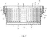
- the swelling member 40 absorbs the electrolyte and is expanded in volume. That is, as illustrated in FIG. 4 that illustrates a state when the swelling member 40 is expanded, the volume of the swelling member 40 is expanded in the space portion C by absorbing the electrolyte.
- the expanded swelling member 40 may buffer an external impact transmitted to the electrode assembly 1. Thus, it may be possible to prevent the electrode assembly 1 from being damaged, thereby further improving durability of the secondary battery.
- the space portion C in which the swelling member 40 is expanded is formed in a radial direction of the upper can 20 and the lower can 10, an increase in height of the secondary battery may be suppressed.
- the swelling member 40 may buffer impact energy transmitted to the electrode assembly 1 by discharging the absorbed electrolyte. Also, as time elapses, the swelling member 40 may again absorb the electrolyte so as to be maintained in buffering performance.
- a plurality of swelling members 40 may be individually coupled to the electrode assembly 1.
- expanded volumes of the swelling members 40 may be provided differently according to a size and shape of a space portion C.
- the lowermost swelling member 40 disposed on a first inclined portion 13 formed with a relatively small inner diameter is expanded to a relatively small size to match an inner diameter formed by the first inclined portion 13.
- each of the swelling members 40 disposed at the first distal end 14 and formed with a relatively larger inner diameter may be expanded to have a diameter greater than that of the lowermost swelling member 40.
- the swelling member 40 may be provided as a swelling tape that is capable of being wound around the electrode assembly 1.
- a tape provided to prevent unwinding may be provided as the swelling member 40.
- the swelling tape 40 may be provided in an attached state during a process of manufacturing the electrode assembly 1, a separate additional assembling process for coupling the swelling member 40 may be deleted.
- the swelling tape may not be attached only to an end at which the winding of any one of the negative electrode, the separator, and the positive electrode is completed, but be attached to being wound around the entire electrode assembly 1 to more efficiently suppress the problem, in which the electrode assembly 1 is unwound by an external impact.
- a surplus space C1 (see FIG. 5 ) may be formed in the space portion C.
- a gas that is generated during charging and discharging of the secondary battery may be collected in the form of air bubbles g.
- the air bubbles g are collected, swelling of the upper can 20 and/or the lower can 10 may be suppressed.
- At least two or more. i.e., the plurality of swelling members 40 may be attached to the electrode assembly 1.
- at least one of the swelling members 40 may be expanded in size that is different from that of the other and thus be expanded to match the shape of the space portion C to more efficiently utilize the inner space.
- the swelling member 40 may be the swelling tape, and the swelling tape may be coupled to be wound around a circumference of the electrode assembly 1, thereby preventing the electrode assembly 1 from being unwound.
- the surplus space C1 may be formed in the space portion C, and thus, when the gas is generated therein, the surplus space C may be used as the space in which the air bubbles are collected.
- the present invention may additionally provide a secondary battery module in which the plurality of button-type secondary batteries having the above characteristics are connected to each other in parallel or in series.
Landscapes
- Chemical & Material Sciences (AREA)
- Chemical Kinetics & Catalysis (AREA)
- Electrochemistry (AREA)
- General Chemical & Material Sciences (AREA)
- Engineering & Computer Science (AREA)
- Manufacturing & Machinery (AREA)
- Secondary Cells (AREA)
- Sealing Battery Cases Or Jackets (AREA)
- Cell Separators (AREA)
Abstract
Description
- The present application claims the benefit of the priority of
Korean Patent Application No. 10-2020-0087138, filed on July 14, 2020 - The present invention relates to a button-type secondary battery having a shape having a diameter greater than a height thereof, and more particularly, to a button-type secondary battery capable of buffering an impact by embedding a swelling member and preventing an electrode assembly from being unwound.
- A button-type battery commonly used as a coin-type battery or a button-type battery has a thin button shape and is widely used in various devices such as remote controllers, clocks, toys, computer parts, and the like.
- Such a button-type battery is mainly manufactured as a non-rechargeable primary battery, but is also widely manufactured as a secondary battery that is chargeable and dischargeable as miniaturized devices are developed. Also, the button-type secondary battery also has a structure in which an electrode assembly and an electrolyte are embedded in a case to repeatedly perform charging and discharging, like a cylindrical or pouch-type secondary battery.
-
FIG. 1 is a cross-sectional view of a button-type secondary battery according to a related art. - As illustrated in the drawing, a button-type secondary battery has a structure, in which an
upper can 4 and alower can 3 are coupled to each other. Here, each of theupper can 4 and thelower can 3 has a flat cylindrical shape having a diameter greater than a height thereof, and theupper can 4 has a diameter slightly greater than that of thelower can 3. - An
electrode assembly 1, in which a positive electrode, a separator, and a negative electrode are stacked, and an electrolyte (not shown) are mounted in thelower can 3. Theelectrode assembly 1 has a structure in which the separator, the negative electrode, the separator, and the positive electrode are put in and wound on a rotating core in order, and acenter pin 2 is inserted into a center hole from which the core is removed. Then, a negative electrode tab extending from the negative electrode and a positive electrode tab extending from the positive electrode protrude, and the negative electrode tab and the positive electrode tab are bonded to thelower can 3 and theupper can 4, respectively. - In addition, in order to prevent short circuit from occurring when the upper can 4 and the
lower can 3 are coupled to each other, an end of theupper can 4 may be coupled to thelower can 3 while being bent to press agasket 5 in a state in which thegasket 5 having no conductivity is disposed at a contact point at which the upper can 4 and thelower can 3 are in contact with each other. - However, in the above-described coupling method, since coupling force is determined only by friction force between the gasket and the upper can and a pressure at which the end of the upper can presses the gasket, when an external impact is applied, the upper can and the lower can may be separated from each other.
- In addition, there is a possibility that the external impact is transmitted to the internal electrode assembly to cause unwinding and damage of the wound electrode assembly.
- Therefore, a main object of the present invention for solving the above problems is to provide a button-type secondary battery having a structure that is more robust to an external impact and is capable of buffering an impact transmitted to an electrode assembly.
- According to the present invention for achieving the above objects, a button-type secondary battery, in which an upper can and a lower can are coupled to each other when an electrode assembly is mounted in the lower can comprises: the electrode assembly in which a negative electrode, a separator, and a positive electrode are wound in a state of being stacked; the lower can in which the electrode assembly is mounted, and a space portion is formed as an extra space in addition to a space in which the electrode assembly is mounted; the upper can coupled to the lower can to close the lower can in a state in which the electrode assembly is mounted in the lower can, and an electrolyte is injected; and a swelling member mounted in the lower can in a state of being coupled to an outer surface of the electrode assembly, wherein, when the electrolyte is injected, the swelling member absorbs the electrolyte to be expanded in volume within the space portion.
- The lower can may comprise: a first sidewall formed upward along a circumference of a flat bottom surface; a first inclined portion formed in a shape of which a diameter gradually increases from an end of the first sidewall; and a first distal end extending in a direction parallel to the first sidewall from an end of the first inclined portion.
- In addition, the upper can may comprise: a second sidewall formed downward along a circumference of a flat top surface and parallel to the first distal end; a second inclined portion formed to have a diameter that is gradually narrowed from an end of the second sidewall and being parallel to the first inclined portion; and a second distal end extending from an end of the second inclined portion so as to be parallel to the first sidewall.
- The space portion may be formed using the first inclined portion, the first distal end, the top surface, and a side surface of the electrode assembly as boundaries.
- A gasket may be placed between the first sidewall and the second distal end, between the first inclined portion and the second inclined portion, and between the first distal end and the second sidewall to prevent the upper can and the lower can from being in contact with each other.
- An end of the gasket may protrude from the second distal end so as to be exposed to the outside.
- At least two or more, i.e., a plurality of swelling members may be attached to the electrode assembly. In addition, any one of the swelling members may be expanded in volume that is different from that of the other.
- The swelling member may be a swelling tape, and the swelling tape may be coupled to surround a circumference of the electrode assembly.
- When the expansion of the swelling member in the space portion is completed, a surplus space may be formed in the space portion.
- Furthermore, the present invention may additionally provide a secondary battery module in which the plurality of button-type secondary batteries having the above characteristics are connected to each other in parallel or in series.
- According to the present invention having the above-described technical characteristics, since the swelling member may absorb the electrolyte in the upper can and the lower can so as to be expanded in volume, it may be possible to buffer the external impact transmitted to the electrode assembly.
- Thus, it may be possible to prevent the electrode assembly from being damaged, thereby further improving the durability of the secondary battery.
- Since the space portion in which the swelling member is expanded is formed in the radial direction of the upper can and the lower can, the increase in height of the secondary battery may be suppressed.
- In addition, since the top surface of the upper can has a diameter greater than that of the bottom surface of the lower can, the sealing performance may be further improved by coupling the upper can to the lower can in the press-fit method.
- In addition, since the lower can and the upper can have the first inclined portion and the second inclined portion, respectively, it may be possible to reduce the impact applied to the gasket when the press- fitting is performed and to enable the more stable coupling.
- At least two or more of the swelling members, i.e., the plurality of swelling members may be attached to the electrode assembly, and at least one of the swelling members may be expanded to be different in size from other swelling members, and thus, the internal space may be efficiently used according to the shape of the space portion.
- Furthermore, the swelling member may be the swelling tape, and the swelling tape may be coupled to surround the circumference of the electrode assembly, thereby preventing the electrode assembly from being unwound.
- In addition, the surplus space may be formed in the space portion, and thus, when the gas is generated therein, the surplus space may be used as the space in which the gas is collected.
-
-
FIG. 1 is a longitudinal cross-sectional view of a button-type secondary battery according to the related art. -
FIG. 2 is a longitudinal cross-sectional view illustrating a state in which a space portion is formed in a lower can according to an embodiment of the present invention. -
FIG. 3 is a longitudinal cross-sectional view illustrating a state in which an electrode assembly, in which a swelling member is coupled in the lower can, is mounted according to an embodiment of the present invention. -
FIG. 4 is a longitudinal cross-sectional view illustrating a state when the swelling member ofFIG. 3 is expanded. -
FIG. 5 is a longitudinal cross-sectional view illustrating a state in which a gas is collected into a surplus space of the space portion. - Hereinafter, preferred embodiments of the present invention will be described in detail with reference to the accompanying drawings in such a manner that the technical idea of the present invention may easily be carried out by a person with ordinary skill in the art to which the invention pertains. The present invention may, however, be embodied in different forms and should not be construed as limited to the embodiments set forth herein.
- In order to clearly describe the present invention, parts irrelevant to the description are omitted, and the same reference numerals are assigned to the same or similar components throughout the specification.
- Also, terms or words used in this specification and claims should not be restrictively interpreted as ordinary meanings or dictionary-based meanings, but should be interpreted as meanings and concepts conforming to the scope of the present invention on the basis of the principle that an inventor can properly define the concept of a term to describe and explain his or her invention in the best ways.
- The present invention relates to a button-type secondary battery having a diameter larger than a height thereof and comprises a
swelling member 40 that is expanded in volume by absorbing an electrolyte. Hereinafter, embodiments of the present invention will be described in detail with reference to the accompanying drawings. -
FIG. 2 is a longitudinal cross-sectional view illustrating a state in which a space portion C is formed in alower can 10, andFIG. 3 is a longitudinal cross-sectional view illustrating a state in which anelectrode assembly 1, in which aswelling member 40 is coupled in the lower can C, is mounted. - Referring to the drawings, in the present invention, the
electrode assembly 1 is mounted in anupper can 20 and thelower can 10, theelectrode assembly 1 is mounted in a state in which theswelling member 40 is coupled, and an electrolyte is injected before theupper can 20 and thelower can 10 are coupled to each other. - The
electrode assembly 1 has a structure in which a negative electrode, a separator, and a positive electrode are wound in a state of being stacked. In addition, apositive electrode tab 1a extending from the positive electrode protrudes upward, and anegative electrode tab 1b extending from the negative electrode protrudes downward. Here, before the lower can 10 and theupper can 20 are coupled to each other, thepositive electrode tab 1a is bonded to theupper can 20, and thenegative electrode tab 1b is bonded to thelower can 10. - Then, the
electrode assembly 1 is mounted in the lower can 10 having a cup shape. In thelower can 10, the space portion C is formed as an extra space in addition to a space in which theelectrode assembly 1 is mounted. That is, as shown in the drawing, an upper end of thelower can 10 has a structure that is expanded along a circumference thereof in a direction in which a diameter thereof increases. - In more detail, the
lower can 10 comprises afirst sidewall 12 formed upward along a circumference of aflat bottom surface 11, a firstinclined portion 13 formed in a shape of which a diameter gradually increases from an end of thefirst sidewall 12, and a firstdistal end 14 extending in a direction parallel to thefirst sidewall 12 from an end of the firstinclined portion 13. - Also, the
upper can 20 is coupled to thelower can 10 to close thelower can 10 in a state in which theelectrode assembly 1 is mounted in thelower can 10, and the electrolyte is injected. Theupper can 20 comprises asecond sidewall 22 formed downward along a circumference of aflat top surface 21 and parallel to the firstdistal end 14, a secondinclined portion 23 formed to have a diameter that is gradually narrowed from an end of thesecond sidewall 22 and being parallel to the firstinclined portion 13, and a seconddistal end 24 extending from an end of the secondinclined portion 23 so as to be parallel to thefirst sidewall 12. - Thus, when the
lower can 10 and theupper can 20 are coupled to each other, the space portion C is formed using the firstinclined portion 13, the firstdistal end 14, thetop surface 21, and a side surface of theelectrode assembly 1 as boundaries. - Furthermore, as described above, since the
upper can 20 is connected to the positive electrode, and thelower can 10 is connected to the negative electrode, a gasket 30 made of a material having an electrical insulation is inserted into the coupled points of theupper can 20 and thelower can 10 to prevent short circuit from occurring. That is, the gasket 30 is placed between thefirst sidewall 12 and the seconddistal end 24, between the firstinclined portion 13 and the secondinclined portion 23, and between the firstdistal end 14 and thesecond sidewall 22 to prevent theupper can 20 and the lower can 10 from being in contact with each other. Here, an end of the gasket 30 protrudes from the seconddistal end 24 by a predetermined length so that an end of the seconddistal end 24 is pressed. - Also, in this embodiment, the
electrode assembly 1 is mounted in thelower can 10 in a state in which the swellingmember 40 is coupled to an outer surface thereof. When theelectrode assembly 1 is mounted in thelower can 10, the swellingmember 40 is coupled to an upper portion of theelectrode assembly 1 so as to be placed in the space portion C. - When the electrolyte is injected into the
lower can 10 after theelectrode assembly 1 is mounted, the swellingmember 40 absorbs the electrolyte and is expanded in volume. That is, as illustrated inFIG. 4 that illustrates a state when the swellingmember 40 is expanded, the volume of the swellingmember 40 is expanded in the space portion C by absorbing the electrolyte. - The expanded swelling
member 40 may buffer an external impact transmitted to theelectrode assembly 1. Thus, it may be possible to prevent theelectrode assembly 1 from being damaged, thereby further improving durability of the secondary battery. In addition, in this embodiment, since the space portion C in which the swellingmember 40 is expanded is formed in a radial direction of theupper can 20 and thelower can 10, an increase in height of the secondary battery may be suppressed. - When an impact is transmitted from the outside, the swelling
member 40 may buffer impact energy transmitted to theelectrode assembly 1 by discharging the absorbed electrolyte. Also, as time elapses, the swellingmember 40 may again absorb the electrolyte so as to be maintained in buffering performance. - In this embodiment, a configuration in which at least two or
more swelling members 40 are coupled to anelectrode assembly 1 is provided. - That is, as illustrated in
FIGS. 2 and3 , a plurality of swellingmembers 40 may be individually coupled to theelectrode assembly 1. Here, expanded volumes of the swellingmembers 40 may be provided differently according to a size and shape of a space portion C. - For example, the lowermost swelling
member 40 disposed on a firstinclined portion 13 formed with a relatively small inner diameter is expanded to a relatively small size to match an inner diameter formed by the firstinclined portion 13. However, each of the swellingmembers 40 disposed at the firstdistal end 14 and formed with a relatively larger inner diameter may be expanded to have a diameter greater than that of the lowermost swellingmember 40. - Furthermore, in this embodiment, the swelling
member 40 may be provided as a swelling tape that is capable of being wound around theelectrode assembly 1. - That is, after the winding of a negative electrode, a separator, and a positive electrode, which constitute the
electrode assembly 1, is completed, a tape provided to prevent unwinding may be provided as the swellingmember 40. Thus, since the swellingtape 40 may be provided in an attached state during a process of manufacturing theelectrode assembly 1, a separate additional assembling process for coupling the swellingmember 40 may be deleted. - Here, the swelling tape may not be attached only to an end at which the winding of any one of the negative electrode, the separator, and the positive electrode is completed, but be attached to being wound around the
entire electrode assembly 1 to more efficiently suppress the problem, in which theelectrode assembly 1 is unwound by an external impact. - As the plurality of swelling
members 40 are attached as described above, a surplus space C1 (seeFIG. 5 ) may be formed in the space portion C. - As illustrated in
FIG. 5 that illustrates a state in which a gas is collected in the surplus space C1, a gas that is generated during charging and discharging of the secondary battery may be collected in the form of air bubbles g. As described above, as the air bubbles g are collected, swelling of theupper can 20 and/or thelower can 10 may be suppressed. - Therefore, in this embodiment, at least two or more. i.e., the plurality of swelling
members 40 may be attached to theelectrode assembly 1. Here, at least one of the swellingmembers 40 may be expanded in size that is different from that of the other and thus be expanded to match the shape of the space portion C to more efficiently utilize the inner space. - Furthermore, the swelling
member 40 may be the swelling tape, and the swelling tape may be coupled to be wound around a circumference of theelectrode assembly 1, thereby preventing theelectrode assembly 1 from being unwound. - In addition, the surplus space C1 may be formed in the space portion C, and thus, when the gas is generated therein, the surplus space C may be used as the space in which the air bubbles are collected.
- Furthermore, the present invention may additionally provide a secondary battery module in which the plurality of button-type secondary batteries having the above characteristics are connected to each other in parallel or in series.
- While the embodiments of the present invention have been described with reference to the specific embodiments, it will be apparent to those skilled in the art that various changes and modifications may be made without departing from the spirit and scope of the invention as defined in the following claims.
-
- 1:
- Electrode assembly
- 10:
- Lower can
- 11:
- Bottom surface
- 12:
- First sidewall
- 13:
- First inclined portion
- 14:
- First distal end
- 20:
- Upper can
- 21:
- Top surface
- 22:
- Second sidewall
- 23:
- Second inclined portion
- 24:
- Second distal end
- 30:
- Gasket
- 40:
- Swelling member.
Claims (10)
- A button-type secondary battery, in which an upper can and a lower can are coupled to each other when an electrode assembly is mounted in the lower can, the button-type secondary battery comprising:the electrode assembly in which a negative electrode, a separator, and a positive electrode are wound in a state of being stacked;the lower can in which the electrode assembly is mounted, and a space portion is formed as an extra space in addition to a space in which the electrode assembly is mounted;the upper can coupled to the lower can to close the lower can in a state in which the electrode assembly is mounted in the lower can, and an electrolyte is injected; anda swelling member mounted in the lower can in a state of being coupled to an outer surface of the electrode assembly,wherein, when the electrolyte is injected, the swelling member absorbs the electrolyte to be expanded in volume within the space portion.
- The button-type secondary battery of claim 1, wherein the lower can comprises: a first sidewall formed upward along a circumference of a flat bottom surface; a first inclined portion formed in a shape of which a diameter gradually increases from an end of the first sidewall; and a first distal end extending in a direction parallel to the first sidewall from an end of the first inclined portion, and
the upper can comprises: a second sidewall formed downward along a circumference of a flat top surface and parallel to the first distal end; a second inclined portion formed to have a diameter that is gradually narrowed from an end of the second sidewall and being parallel to the first inclined portion; and a second distal end extending from an end of the second inclined portion so as to be parallel to the first sidewall. - The button-type secondary battery of claim 2, wherein the space portion is formed using the first inclined portion, the first distal end, the top surface, and a side surface of the electrode assembly as boundaries.
- The button-type secondary battery of claim 2, wherein a gasket is placed between the first sidewall and the second distal end, between the first inclined portion and the second inclined portion, and between the first distal end and the second sidewall to prevent the upper can and the lower can from being in contact with each other.
- The button-type secondary battery of claim 4, wherein an end of the gasket protrudes from the second distal end so as to be exposed to the outside.
- The button-type secondary battery of claim 1, wherein at least two or more, i.e., a plurality of swelling members are attached to the electrode assembly.
- The button-type secondary battery of claim 6, wherein any one of the swelling members is expanded in volume that is different from that of the other.
- The button-type secondary battery of claim 1, wherein the swelling member is a swelling tape, and the swelling tape is coupled to surround a circumference of the electrode assembly.
- The button-type secondary battery of claim 1, wherein, when the expansion of the swelling member in the space portion is completed, a surplus space is formed in the space portion.
- A secondary battery module, in which the plurality of button-type secondary batteries of any one of claims 1 to 9 are electrically connected to each other.
Applications Claiming Priority (2)
| Application Number | Priority Date | Filing Date | Title |
|---|---|---|---|
| KR1020200087138A KR20220008684A (en) | 2020-07-14 | 2020-07-14 | Button type secondary battery |
| PCT/KR2021/009058 WO2022015056A1 (en) | 2020-07-14 | 2021-07-14 | Button-type secondary battery |
Publications (2)
| Publication Number | Publication Date |
|---|---|
| EP4084196A1 true EP4084196A1 (en) | 2022-11-02 |
| EP4084196A4 EP4084196A4 (en) | 2024-02-14 |
Family
ID=79555739
Family Applications (1)
| Application Number | Title | Priority Date | Filing Date |
|---|---|---|---|
| EP21842000.8A Pending EP4084196A4 (en) | 2020-07-14 | 2021-07-14 | Button-type secondary battery |
Country Status (6)
| Country | Link |
|---|---|
| US (1) | US20230143427A1 (en) |
| EP (1) | EP4084196A4 (en) |
| JP (1) | JP7428318B2 (en) |
| KR (1) | KR20220008684A (en) |
| CN (1) | CN115004460A (en) |
| WO (1) | WO2022015056A1 (en) |
Family Cites Families (19)
| Publication number | Priority date | Publication date | Assignee | Title |
|---|---|---|---|---|
| TW522582B (en) * | 2000-10-05 | 2003-03-01 | Matsushita Electric Ind Co Ltd | Pancake battery and manufacturing method thereof |
| JP4020580B2 (en) | 2000-10-13 | 2007-12-12 | 松下電器産業株式会社 | Flat rectangular battery |
| JP2003045381A (en) | 2001-07-31 | 2003-02-14 | Matsushita Electric Ind Co Ltd | Coin-shaped battery |
| JP2003288875A (en) | 2002-03-28 | 2003-10-10 | Matsushita Electric Ind Co Ltd | Coin-shaped cell |
| JP4070136B2 (en) * | 2004-08-30 | 2008-04-02 | 日立マクセル株式会社 | Coin battery |
| KR100719725B1 (en) * | 2005-12-29 | 2007-05-17 | 삼성에스디아이 주식회사 | Electrode assembly for lithium rechargeable battery and lithium rechargeable battery using the same |
| JP2007294111A (en) | 2006-04-20 | 2007-11-08 | Toshiba Battery Co Ltd | Compact battery |
| US8003251B2 (en) | 2006-12-07 | 2011-08-23 | Rovcal, Inc. | Electrochemical cell grommet having a sidewall with a nonuniform thickness |
| KR101163387B1 (en) * | 2008-02-16 | 2012-07-12 | 주식회사 엘지화학 | Secondary Battery Containing Jelly-Roll Typed Electrode Assembly |
| US9153835B2 (en) * | 2009-02-09 | 2015-10-06 | Varta Microbattery Gmbh | Button cells and method for producing same |
| CN102549801B (en) | 2010-10-04 | 2016-05-25 | 株式会社Lg化学 | The secondary cell of band and the described band of use |
| CN102694202B (en) * | 2012-06-29 | 2014-07-30 | 广东凯德能源科技有限公司 | Button type lithium ion battery |
| JP6283288B2 (en) | 2014-09-03 | 2018-02-21 | マクセルホールディングス株式会社 | Flat non-aqueous secondary battery |
| EP3151303B1 (en) * | 2015-09-30 | 2019-09-11 | VARTA Microbattery GmbH | Semi-finished product, method for the preparation of a button cell and a button cell |
| KR102140689B1 (en) * | 2016-06-08 | 2020-08-04 | 주식회사 엘지화학 | Lithium secondary battery |
| KR102071592B1 (en) * | 2016-09-21 | 2020-03-02 | 주식회사 엘지화학 | Rechargeable battery |
| US20200044276A1 (en) * | 2017-01-31 | 2020-02-06 | Panasonic Intellectual Property Management Co., Ltd. | Secondary battery |
| CN107195807A (en) * | 2017-06-06 | 2017-09-22 | 惠州亿纬锂能股份有限公司 | Chargeable miniature lithium ion battery with hard shell structure and preparation method |
| CN210224197U (en) * | 2019-08-23 | 2020-03-31 | 重庆市紫建电子有限公司 | External welding type winding type button battery |
-
2020
- 2020-07-14 KR KR1020200087138A patent/KR20220008684A/en active Search and Examination
-
2021
- 2021-07-14 CN CN202180010748.8A patent/CN115004460A/en active Pending
- 2021-07-14 EP EP21842000.8A patent/EP4084196A4/en active Pending
- 2021-07-14 US US17/798,233 patent/US20230143427A1/en active Pending
- 2021-07-14 WO PCT/KR2021/009058 patent/WO2022015056A1/en unknown
- 2021-07-14 JP JP2022543041A patent/JP7428318B2/en active Active
Also Published As
| Publication number | Publication date |
|---|---|
| CN115004460A (en) | 2022-09-02 |
| WO2022015056A1 (en) | 2022-01-20 |
| JP2023510376A (en) | 2023-03-13 |
| KR20220008684A (en) | 2022-01-21 |
| JP7428318B2 (en) | 2024-02-06 |
| EP4084196A4 (en) | 2024-02-14 |
| US20230143427A1 (en) | 2023-05-11 |
Similar Documents
| Publication | Publication Date | Title |
|---|---|---|
| CN110462881B (en) | Flexible battery with reinforced tab junction structure and electrode lead bending structure | |
| CN111418082B (en) | secondary battery | |
| KR100670454B1 (en) | Cylindrical Li Secondary Battery | |
| CN100517851C (en) | Cylindrical lithium secondary battery | |
| US9318732B2 (en) | Lithium rechargeable battery | |
| KR100659881B1 (en) | Lithium ion battery | |
| CN105609862B (en) | Rechargeable battery | |
| US20130115490A1 (en) | Rechargeable battery | |
| CN106463661A (en) | Battery cell | |
| KR20060111838A (en) | Cylindrical li secondary battery and method of fabricating the same | |
| EP3079195A1 (en) | Secondary battery | |
| EP4084196A1 (en) | Button-type secondary battery | |
| JP4594244B2 (en) | Cylindrical lithium secondary battery | |
| EP4089778A1 (en) | Button-type secondary battery | |
| JP2007188711A (en) | Sealed battery | |
| US9196919B2 (en) | Secondary battery and manufacturing method of the same | |
| JP2006093146A (en) | Cap assembly and lithium secondary battery using same | |
| KR20220108600A (en) | Button-type secondary battery | |
| US8663838B2 (en) | Cylindrical secondary battery including center pin having improved structure | |
| KR101469466B1 (en) | Battery pack comprising protection circuit module of improved assemble function | |
| EP4087033A1 (en) | Button-type secondary battery | |
| EP4195376A1 (en) | Button-type secondary battery | |
| CN220492155U (en) | Button secondary battery and secondary battery module | |
| CN219610527U (en) | Battery monomer, battery and power consumption device | |
| CN209947880U (en) | Lithium ion battery |
Legal Events
| Date | Code | Title | Description |
|---|---|---|---|
| STAA | Information on the status of an ep patent application or granted ep patent |
Free format text: STATUS: THE INTERNATIONAL PUBLICATION HAS BEEN MADE |
|
| PUAI | Public reference made under article 153(3) epc to a published international application that has entered the european phase |
Free format text: ORIGINAL CODE: 0009012 |
|
| STAA | Information on the status of an ep patent application or granted ep patent |
Free format text: STATUS: REQUEST FOR EXAMINATION WAS MADE |
|
| 17P | Request for examination filed |
Effective date: 20220729 |
|
| AK | Designated contracting states |
Kind code of ref document: A1 Designated state(s): AL AT BE BG CH CY CZ DE DK EE ES FI FR GB GR HR HU IE IS IT LI LT LU LV MC MK MT NL NO PL PT RO RS SE SI SK SM TR |
|
| DAV | Request for validation of the european patent (deleted) | ||
| DAX | Request for extension of the european patent (deleted) | ||
| A4 | Supplementary search report drawn up and despatched |
Effective date: 20240115 |
|
| RIC1 | Information provided on ipc code assigned before grant |
Ipc: H01M 50/56 20210101ALI20240109BHEP Ipc: H01M 50/545 20210101ALI20240109BHEP Ipc: H01M 50/538 20210101ALI20240109BHEP Ipc: H01M 50/14 20210101ALI20240109BHEP Ipc: H01M 50/489 20210101ALI20240109BHEP Ipc: H01M 10/04 20060101ALI20240109BHEP Ipc: H01M 50/109 20210101ALI20240109BHEP Ipc: H01M 50/153 20210101ALI20240109BHEP Ipc: H01M 50/183 20210101ALI20240109BHEP Ipc: H01M 50/166 20210101AFI20240109BHEP |