EP4084167A2 - Brennstoffzellenverteileranordnung mit einer selbsttragenden polymermaterialauskleidung - Google Patents
Brennstoffzellenverteileranordnung mit einer selbsttragenden polymermaterialauskleidung Download PDFInfo
- Publication number
- EP4084167A2 EP4084167A2 EP22179327.6A EP22179327A EP4084167A2 EP 4084167 A2 EP4084167 A2 EP 4084167A2 EP 22179327 A EP22179327 A EP 22179327A EP 4084167 A2 EP4084167 A2 EP 4084167A2
- Authority
- EP
- European Patent Office
- Prior art keywords
- liner
- primary wall
- manifold
- assembly
- flange
- Prior art date
- Legal status (The legal status is an assumption and is not a legal conclusion. Google has not performed a legal analysis and makes no representation as to the accuracy of the status listed.)
- Granted
Links
Images

Classifications
-
- H—ELECTRICITY
- H01—ELECTRIC ELEMENTS
- H01M—PROCESSES OR MEANS, e.g. BATTERIES, FOR THE DIRECT CONVERSION OF CHEMICAL ENERGY INTO ELECTRICAL ENERGY
- H01M8/00—Fuel cells; Manufacture thereof
- H01M8/24—Grouping of fuel cells, e.g. stacking of fuel cells
- H01M8/2465—Details of groupings of fuel cells
- H01M8/2484—Details of groupings of fuel cells characterised by external manifolds
-
- H—ELECTRICITY
- H01—ELECTRIC ELEMENTS
- H01M—PROCESSES OR MEANS, e.g. BATTERIES, FOR THE DIRECT CONVERSION OF CHEMICAL ENERGY INTO ELECTRICAL ENERGY
- H01M8/00—Fuel cells; Manufacture thereof
- H01M8/08—Fuel cells with aqueous electrolytes
- H01M8/086—Phosphoric acid fuel cells [PAFC]
-
- H—ELECTRICITY
- H01—ELECTRIC ELEMENTS
- H01M—PROCESSES OR MEANS, e.g. BATTERIES, FOR THE DIRECT CONVERSION OF CHEMICAL ENERGY INTO ELECTRICAL ENERGY
- H01M8/00—Fuel cells; Manufacture thereof
- H01M8/04—Auxiliary arrangements, e.g. for control of pressure or for circulation of fluids
- H01M8/04082—Arrangements for control of reactant parameters, e.g. pressure or concentration
- H01M8/04201—Reactant storage and supply, e.g. means for feeding, pipes
-
- H—ELECTRICITY
- H01—ELECTRIC ELEMENTS
- H01M—PROCESSES OR MEANS, e.g. BATTERIES, FOR THE DIRECT CONVERSION OF CHEMICAL ENERGY INTO ELECTRICAL ENERGY
- H01M8/00—Fuel cells; Manufacture thereof
- H01M8/24—Grouping of fuel cells, e.g. stacking of fuel cells
- H01M8/2465—Details of groupings of fuel cells
- H01M8/2484—Details of groupings of fuel cells characterised by external manifolds
- H01M8/2485—Arrangements for sealing external manifolds; Arrangements for mounting external manifolds around a stack
-
- Y—GENERAL TAGGING OF NEW TECHNOLOGICAL DEVELOPMENTS; GENERAL TAGGING OF CROSS-SECTIONAL TECHNOLOGIES SPANNING OVER SEVERAL SECTIONS OF THE IPC; TECHNICAL SUBJECTS COVERED BY FORMER USPC CROSS-REFERENCE ART COLLECTIONS [XRACs] AND DIGESTS
- Y02—TECHNOLOGIES OR APPLICATIONS FOR MITIGATION OR ADAPTATION AGAINST CLIMATE CHANGE
- Y02E—REDUCTION OF GREENHOUSE GAS [GHG] EMISSIONS, RELATED TO ENERGY GENERATION, TRANSMISSION OR DISTRIBUTION
- Y02E60/00—Enabling technologies; Technologies with a potential or indirect contribution to GHG emissions mitigation
- Y02E60/30—Hydrogen technology
- Y02E60/50—Fuel cells
Definitions
- Fuel cell devices provide electricity based on an electrochemical reaction. Some fuel cell arrangements utilize phosphoric acid as an electrolyte. Such fuel cells are often referred to as phosphoric acid fuel cells (PAFC).
- PAFC phosphoric acid fuel cells
- Fuel cell power plants typically include cell stack assemblies having multiple fuel cells.
- a manifold may be situated along at least one side of the cell stack assembly for directing reactants to the fuel cells.
- the manifolds are carbon steel and have to be protected from the phosphoric acid.
- a common approach includes electrostatically coating the manifold pan with a perfluoroalkoxy polymer resin (PFA) coating. While such coatings provide a useful acid barrier and serve as a dielectric barrier on the metal manifold pan, utilizing such coatings introduces additional expense. Multiple coating and sintering steps typically are required to develop a coating that is thick enough to be an effective barrier.
- PFA perfluoroalkoxy polymer resin
- An illustrative example embodiment of a fuel cell manifold device includes a self-supporting polymer material liner body including a generally planar primary wall and a plurality of side walls.
- the side walls respectively extend generally perpendicularly from the primary wall. Interior surfaces on the primary wall and the side walls collectively define a cavity.
- the primary wall has a length and a width that is smaller than the length.
- the primary wall includes a plurality of ribs situated width wise along the primary wall. The ribs are spaced apart from each other in a lengthwise direction. The ribs provide flexibility to allow for some thermal expansion of the liner body.
- the fuel cell manifold device may comprise a plurality of lips respectively near an end of the sidewalls distal from the primary wall, the lips being generally parallel to the primary wall.
- the fuel cell manifold device may comprise a channel around a periphery of the body, the channel having one side defined by at least a portion of the sidewalls, the channel facing in an opposite direction from the interior surface of the primary wall.
- the channel may have a first width near one end of the primary wall and a second, larger width near an opposite end of the primary wall.
- the fuel cell manifold device may comprise a metal manifold tray including edges that are received in the channel, an interior side of the metal manifold tray being situated adjacent an exterior surface on the primary wall of the liner body.
- the fuel cell manifold device may comprise:
- the reactant conduit adapter may include a flange that is received against the interior surface of the primary wall; and the flange at least partially surrounds the opening through the primary wall.
- the fuel cell manifold device may comprise a plurality of fasteners that secure the flange to the primary wall.
- the fuel cell manifold device may comprise a metal manifold pan situated adjacent an exterior surface of the primary wall, the metal manifold pan having an opening through the metal manifold pan that is aligned with the opening through the primary wall of the liner body.
- the fuel cell manifold device may comprise a plurality of fasteners that secure the flange to the metal manifold pan with a portion of the primary wall between the flange and the metal manifold pan.
- An illustrative example fuel cell manifold assembly includes a metal manifold pan.
- a polymer material liner that is self-supporting includes a primary wall situated adjacent an interior of the manifold pan.
- the liner has a channel around a periphery of the liner and a portion of the manifold is received in the channel.
- a reactant conduit adapter is received through respective openings in the manifold pan and the liner.
- the reactant conduit adaptor includes a flange that is received against an interior surface on the primary wall of the liner with an interface between the flange and the interior surface being sealed. Another portion of the reactant conduit adaptor is adjacent an exterior of the manifold pan that faces in an opposite direction from the interior surface on the primary wall.
- the channel has a first width near one end of the primary wall and a second, larger width near an opposite end of the primary wall.
- the flange may surround the opening in the primary wall.
- the assembly may comprise a plurality of fasteners that secure the flange to the manifold pan with a portion of the primary wall between the flange and the manifold pan.
- the assembly may comprise a seal associated with each of the fasteners, the seal being configured to prevent gas or acid migration from inside the liner toward the manifold pan.
- the liner may include a plurality of sidewalls, the sidewalls respectively extending generally perpendicularly from the primary wall, the interior surface on the primary wall and interior surfaces on the sidewalls collectively defining a cavity.
- the primary wall may have a length and a width that is smaller than the length
- the length of the primary wall may be at least two meters.
- the channel may face in an opposite direction from the interior surface of the primary wall.
- the another portion of the reactant conduit adapter may have a tube shape.
- the assembly may comprise a seal between the flange and the interior surface on the primary wall.
- An illustrative example method of assembling a fuel cell manifold device includes situating a self-supporting polymer liner adjacent an interior of a metal manifold pan with an edge of the manifold pan received at least partially in a channel around the periphery of the liner. A portion of a reactant conduit adaptor is inserted through an opening in the liner and the manifold pan until a flange on the reactant conduit adaptor is received against an interior surface on the liner. The flange has an outside dimension that is larger than the opening. The flange is then secured to the manifold pan with the liner between the flange and the manifold pan. An interface between the flange and the liner is sealed when the flange is secured.
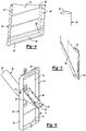
- Figure 1 schematically illustrates selected portions of a fuel cell power plant 20 for generating electricity based on an electrochemical reaction.
- a plurality of individual fuel cells are assembled in a known manner in a cell stack assembly 22.
- a manifold assembly 24 situated along one side of the cell stack assembly 22 facilitates providing reactant to the fuel cells.
- Another manifold assembly 26 is provided on another side of the cell stack assembly 22.
- the manifold assembly 24 includes a metal manifold pan 30 that has a primary wall 32 and a plurality of side walls 34 that extend generally perpendicularly from edges of the primary wall 32.
- the interior surfaces on the primary wall 32 and the side walls 34 define a cavity established by the metal manifold pan 30.
- the primary wall 32 has an opening 36.
- a self-supporting polymer material liner 40 is situated adjacent the interior of the metal manifold pan 30.
- the liner 40 has a primary wall 42 and a plurality of side walls 44 extending generally perpendicularly from edges of the primary wall 42. Lips 46 at the ends of the side walls 44 distal from the primary wall 42 include a portion that is parallel to the primary wall 42 and a portion that is parallel to the corresponding side wall 44.
- the side walls 44 and lips 46 establish a channel around a periphery of the body of the liner 40.
- the channel faces in an opposite direction from an interior surface on the primary wall 42.
- the interior surface of the primary wall 42 is visible.
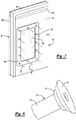
- at least a portion of the side walls 34 on the manifold pan 30 are received in the channel and the primary wall 42 of the liner 40 is received adjacent the primary wall 32 of the manifold pan 30.
- An opening 48 in the primary wall 42 is aligned with the opening 36 when the liner 40 and the pan 30 are placed adjacent each other.
- the body of the liner 40 has a length L and a width W that is smaller than the length. In some example embodiments, the length is greater than two meters (six feet).
- the liner 40 is self-supporting or freestanding in that it maintains its shape independent of being received adjacent the manifold pan 30.
- the liner 40 in this example is made from a thermoplastic polymer that is resistant to acid and water vapor.
- the polymer material of the liner 40 has good strength at high temperature, is thermoformable, and relatively inexpensive so that the liner 40 establishes an effective acid barrier inside the manifold assembly 24 in an economical manner.
- An example material that is useful for example embodiments of the liner 40 is polyphenylsulfone (PPSU). That material is useful because it has good chemical resistance properties, good high temperature properties (e.g., low expansion coefficient and high strength) and is relatively inexpensive.
- Other embodiments include materials for the liner 40, such as poly ether ether ketone (PEEK), polyaryletherketone (PAEK), and polyphenylene sulfide (PPS). Such materials are preferred over polytetrafluoroethylene (PTFE) because the latter does not have adequate high temperature mechanical properties.
- An example embodiment includes using a thermoforming technique to form the liner 40, such as drape forming.
- the thermoforming technique for forming the liner 40 allows for rapid fabrication of the liner, which saves time and manufacturing expense.
- a thermoforming technique contributes to the self-supporting character of the liner 40. Additionally, the freestanding, self-supporting liner 40 can be quickly and relatively simply assembled with the metal manifold pan 30 during an assembly process.
- the terms self-supporting or free-standing mean that the liner has a defined shape and that the liner body is at least capable of maintaining its own shape without requiring another component next to it.
- the liner body 40 defines a cavity based on its self-supporting character.
- the self-supporting aspects of the liner include having the sidewalls 44 situated generally parallel to the primary wall 42.
- the illustrated example liner 40 includes a plurality of ribs 50 that extend widthwise on the body of the liner 40.
- the ribs 50 are spaced apart from each other in a lengthwise direction. In the illustrated example, the ribs 50 are approximately six inches (0.15 meters) apart.
- the ribs 50 provide flexibility to allow for some thermal expansion of the body of the liner 40.
- the ribs 50 for expansion of material to mitigate thermal expansion effects when the liner 40 is subjected to high temperatures during fuel cell operation.
- the ribs 50 also reduce deflection of the liner that otherwise would occur as a result of thermal expansion of the polymer when exposed to higher fuel cell operating temperatures.
- the ribs 50 provide localized regions or areas of the liner 40 that can undergo some thermal expansion while the overall shape of the liner remains unchanged. For example, one or more of the ribs 50 may at least partially flatten out as heat associated with fuel cell operation causes or induces thermal expansion in a lengthwise direction.
- the channel around the periphery of the liner 40 has a larger width near one end of the liner 40.
- the channel has a greater width near the bottom (according to the illustration) of the liner body.
- the wider width in the channel accommodates variations in the manufactured size of a manifold pan 30 or liner 40.
- the larger width of the channel near one end of the liner 40 accommodates manufacturing tolerances associated with making the manifold pan 30 and the liner 40 as separate pieces.
- a wider portion of the channel exists near both ends of the liner 40.
- a reactant conduit adaptor 60 facilitates connecting a source of reactant with the manifold assembly 24.
- One end 62 of the adaptor 60 is situated on an exterior side of the manifold assembly 24 near an outwardly facing surface of the manifold pan 30.
- a flange 64 is provided on an opposite end of the adaptor 60 with a seal 66 on one side of the flange 64.
- the seal 66 may be a separate gasket, a coating or a layer of material on the side of the flange 64 that faces the primary wall 42 of the liner 40.
- the dimension of the flange 64 is larger than the dimension of the opening 36 in the manifold pan 30 and the opening 48 in the liner 40.
- the first end 62 is inserted through the openings 38 and 36 from an interior side of the liner 40.
- a transition portion 68 of the adaptor 60 fits through the openings 36 and 48 and has a portion with an outside dimension that is approximately the same as the size of the openings 36 and 48.
- the adaptor 60 is manipulated until the flange 64 is received against the interior surface of the primary wall 42 of the liner 40.
- a plurality of fasteners 70 have a portion 72 that is configured to cooperate with and be secured to the manifold pan 30.
- the portion 72 is threaded and the manifold pan 30 includes threaded holes surrounding the opening 36.
- the fasteners 70 include a seal 74 that is received against the flange 64 when the fasteners are fully inserted into place to secure the flange 64 against the primary wall 42 of the liner.
- a head portion 76 on the fastener 70 is larger than the size of holes 78 through the flange 64 to maintain the adaptor 60 in a desired position relative to the manifold pan 30 and liner 40 with an interface between the flange 64 and the interior surface of the primary wall 42 sealed by the seal 66.
- a manifold assembly of the type shown in the example embodiment provides cost savings for PAFC systems.
- the self-supporting, freestanding liner 40 is easier and less expensive to make compared to applying a coating to a metal manifold pan.
- the time, material and processing savings associated with the liner 40 makes the manifold assembly 24 and the overall PAFC system more economical.
Landscapes
- Life Sciences & Earth Sciences (AREA)
- Engineering & Computer Science (AREA)
- Manufacturing & Machinery (AREA)
- Sustainable Development (AREA)
- Sustainable Energy (AREA)
- Chemical & Material Sciences (AREA)
- Chemical Kinetics & Catalysis (AREA)
- Electrochemistry (AREA)
- General Chemical & Material Sciences (AREA)
- Fuel Cell (AREA)
Applications Claiming Priority (3)
| Application Number | Priority Date | Filing Date | Title |
|---|---|---|---|
| US15/242,846 US10177397B2 (en) | 2016-08-22 | 2016-08-22 | Fuel cell manifold assembly including a self-supporting polymer material liner |
| EP17844163.0A EP3501056B1 (de) | 2016-08-22 | 2017-08-17 | Brennstoffzellenverteileranordnung mit einer selbsttragenden polymermaterialauskleidung |
| PCT/US2017/047338 WO2018039032A1 (en) | 2016-08-22 | 2017-08-17 | Fuel cell manifold assembly including a self-supporting polymer material liner |
Related Parent Applications (2)
| Application Number | Title | Priority Date | Filing Date |
|---|---|---|---|
| EP17844163.0A Division EP3501056B1 (de) | 2016-08-22 | 2017-08-17 | Brennstoffzellenverteileranordnung mit einer selbsttragenden polymermaterialauskleidung |
| EP17844163.0A Division-Into EP3501056B1 (de) | 2016-08-22 | 2017-08-17 | Brennstoffzellenverteileranordnung mit einer selbsttragenden polymermaterialauskleidung |
Publications (4)
| Publication Number | Publication Date |
|---|---|
| EP4084167A2 true EP4084167A2 (de) | 2022-11-02 |
| EP4084167A3 EP4084167A3 (de) | 2023-01-25 |
| EP4084167C0 EP4084167C0 (de) | 2024-04-10 |
| EP4084167B1 EP4084167B1 (de) | 2024-04-10 |
Family
ID=61192221
Family Applications (2)
| Application Number | Title | Priority Date | Filing Date |
|---|---|---|---|
| EP17844163.0A Active EP3501056B1 (de) | 2016-08-22 | 2017-08-17 | Brennstoffzellenverteileranordnung mit einer selbsttragenden polymermaterialauskleidung |
| EP22179327.6A Active EP4084167B1 (de) | 2016-08-22 | 2017-08-17 | Brennstoffzellenverteileranordnung mit einer selbsttragenden polymermaterialauskleidung |
Family Applications Before (1)
| Application Number | Title | Priority Date | Filing Date |
|---|---|---|---|
| EP17844163.0A Active EP3501056B1 (de) | 2016-08-22 | 2017-08-17 | Brennstoffzellenverteileranordnung mit einer selbsttragenden polymermaterialauskleidung |
Country Status (9)
| Country | Link |
|---|---|
| US (2) | US10177397B2 (de) |
| EP (2) | EP3501056B1 (de) |
| JP (1) | JP7186692B2 (de) |
| KR (1) | KR102503589B1 (de) |
| CN (2) | CN116014208B (de) |
| AU (2) | AU2017316485B2 (de) |
| CA (1) | CA3032831A1 (de) |
| WO (1) | WO2018039032A1 (de) |
| ZA (1) | ZA201901660B (de) |
Families Citing this family (4)
| Publication number | Priority date | Publication date | Assignee | Title |
|---|---|---|---|---|
| US10857688B2 (en) * | 2018-02-11 | 2020-12-08 | Chao-Ying LEE | Method and system of rivering filtration for power saw machine |
| US12539550B2 (en) * | 2018-02-11 | 2026-02-03 | Chao-Ying LEE | Method and system of rivering filtration for power saw machine |
| US10857604B2 (en) * | 2018-02-11 | 2020-12-08 | Chao-Ying LEE | Method and system of rivering filtration for power saw machine |
| FR3120162B1 (fr) * | 2021-02-24 | 2023-11-10 | Powidian | Déflecteur et ensemble comprenant un tel déflecteur |
Citations (1)
| Publication number | Priority date | Publication date | Assignee | Title |
|---|---|---|---|---|
| US6245454B1 (en) | 1997-02-07 | 2001-06-12 | Kabushiki Kaisha Toshiba | Fuel cell and method of installing linings on gas manifolds of fuel cell |
Family Cites Families (16)
| Publication number | Priority date | Publication date | Assignee | Title |
|---|---|---|---|---|
| US4212929A (en) | 1979-04-06 | 1980-07-15 | The United States Of America As Represented By The United States Department Of Energy | Fuel cell manifold sealing system |
| JPS58197679A (ja) * | 1982-05-12 | 1983-11-17 | Sanyo Electric Co Ltd | 燃料電池 |
| JPH0624134B2 (ja) * | 1983-12-09 | 1994-03-30 | 株式会社東芝 | 燃料電池 |
| JPS61173469A (ja) * | 1985-01-26 | 1986-08-05 | Toshiba Corp | 燃料電池 |
| JPS6398970A (ja) * | 1986-10-16 | 1988-04-30 | Fuji Electric Co Ltd | 燃料電池マニホ−ルド |
| JPH08241728A (ja) * | 1995-03-06 | 1996-09-17 | Toshiba Corp | 燃料電池用耐リン酸ガスマニホールド |
| WO1999022413A1 (en) | 1997-10-28 | 1999-05-06 | Kabushiki Kaisha Toshiba | A fuel cell with a gas manifold |
| JPH11260391A (ja) * | 1998-01-08 | 1999-09-24 | Fuji Electric Co Ltd | リン酸型燃料電池用マニホールド |
| US6887611B2 (en) * | 2000-08-11 | 2005-05-03 | Michael Cramer | Flexible fuel cell gas manifold system |
| US7494736B2 (en) | 2004-12-23 | 2009-02-24 | Fuelcell Energy, Inc. | Dielectric frame assembly and fuel cell manifold |
| US7771519B2 (en) | 2005-01-03 | 2010-08-10 | Air Products And Chemicals, Inc. | Liners for ion transport membrane systems |
| US7807316B2 (en) | 2006-11-01 | 2010-10-05 | Gm Global Technology Operations, Inc. | Fuel cell stack compression retention system with external springs |
| WO2010062281A1 (en) | 2008-11-26 | 2010-06-03 | Utc Power Corporation | External manifold for minimizing external leakage of reactant from cell stack |
| JP6213894B2 (ja) * | 2012-09-25 | 2017-10-18 | Toto株式会社 | 固体酸化物型燃料電池装置 |
| CN103996868B (zh) * | 2013-02-18 | 2016-06-15 | 本田技研工业株式会社 | 燃料电池堆 |
| KR101755771B1 (ko) * | 2014-11-13 | 2017-07-07 | 현대자동차주식회사 | 연료전지 차량의 매니폴드 블록 어셈블리 |
-
2016
- 2016-08-22 US US15/242,846 patent/US10177397B2/en active Active
-
2017
- 2017-08-17 EP EP17844163.0A patent/EP3501056B1/de active Active
- 2017-08-17 CA CA3032831A patent/CA3032831A1/en active Pending
- 2017-08-17 KR KR1020197007853A patent/KR102503589B1/ko active Active
- 2017-08-17 EP EP22179327.6A patent/EP4084167B1/de active Active
- 2017-08-17 CN CN202310195155.4A patent/CN116014208B/zh active Active
- 2017-08-17 WO PCT/US2017/047338 patent/WO2018039032A1/en not_active Ceased
- 2017-08-17 AU AU2017316485A patent/AU2017316485B2/en active Active
- 2017-08-17 CN CN201780051646.4A patent/CN109891650A/zh active Pending
- 2017-08-17 JP JP2019510609A patent/JP7186692B2/ja active Active
-
2018
- 2018-11-21 US US16/197,881 patent/US10903514B2/en active Active
-
2019
- 2019-03-18 ZA ZA201901660A patent/ZA201901660B/en unknown
-
2023
- 2023-05-02 AU AU2023202688A patent/AU2023202688B2/en active Active
Patent Citations (1)
| Publication number | Priority date | Publication date | Assignee | Title |
|---|---|---|---|---|
| US6245454B1 (en) | 1997-02-07 | 2001-06-12 | Kabushiki Kaisha Toshiba | Fuel cell and method of installing linings on gas manifolds of fuel cell |
Also Published As
| Publication number | Publication date |
|---|---|
| EP4084167C0 (de) | 2024-04-10 |
| EP3501056A4 (de) | 2020-04-15 |
| JP2019525434A (ja) | 2019-09-05 |
| EP4084167B1 (de) | 2024-04-10 |
| EP3501056A1 (de) | 2019-06-26 |
| US20180053960A1 (en) | 2018-02-22 |
| CA3032831A1 (en) | 2018-03-01 |
| CN116014208B (zh) | 2026-01-02 |
| AU2017316485B2 (en) | 2023-02-23 |
| KR102503589B1 (ko) | 2023-02-23 |
| ZA201901660B (en) | 2019-11-27 |
| EP3501056B1 (de) | 2022-08-03 |
| EP4084167A3 (de) | 2023-01-25 |
| KR20190034678A (ko) | 2019-04-02 |
| US20190097254A1 (en) | 2019-03-28 |
| AU2023202688A1 (en) | 2023-05-18 |
| WO2018039032A1 (en) | 2018-03-01 |
| US10903514B2 (en) | 2021-01-26 |
| AU2017316485A1 (en) | 2019-02-07 |
| CN116014208A (zh) | 2023-04-25 |
| AU2023202688B2 (en) | 2024-05-02 |
| CN109891650A (zh) | 2019-06-14 |
| US10177397B2 (en) | 2019-01-08 |
| JP7186692B2 (ja) | 2022-12-09 |
Similar Documents
| Publication | Publication Date | Title |
|---|---|---|
| AU2023202688B2 (en) | Fuel cell manifold assembly including a self-supporting polymer material liner | |
| US9531021B2 (en) | Fuel cell stack discrete header | |
| EP3204974B1 (de) | Elektrochemisches system mit einem separator mit einer lippendichtung mit reduzierung oder verschluss des kühlmitteldurchflusskanals im innenraum der lippe | |
| US10374238B2 (en) | Fuel cell stack | |
| KR20100045448A (ko) | 양자 교환막 연료전지용의 개스킷 및 바이폴라 플레이트의 개량 | |
| US20130171545A1 (en) | Fuel cell having minimum incidence of leaks | |
| US11217814B2 (en) | Fuel battery stack | |
| US8268504B2 (en) | Thermomechanical sealing of interconnect manifolds in fuel cell stacks | |
| US20080138684A1 (en) | Compact fuel cell stack with uniform depth flow fields | |
| EP3660965B1 (de) | Brennstoffzellensystem | |
| CA2612565A1 (en) | A bipolar plate, a method for the production of a bipolar plate and a fuel cell block arrangement | |
| US20220231353A1 (en) | Fluid-Temperature-Controllable Traction Battery and Battery Housing Assembly Having a Feed-Through for a Heat Transmission Device | |
| US20150065331A1 (en) | High temperature expandable refractory | |
| CN117321810B (zh) | 燃料电池堆叠体、双极板和垫片的总成以及在双极板周围提供密封的方法 | |
| EP3054514B1 (de) | Separatorplatteneinheit für eine Brennstoffzelle und Brennstoffzelle damit mit verbesserter Leistung | |
| CN222008034U (zh) | 炉管组件以及反应炉 | |
| US20080138665A1 (en) | Compact fuel cell stack with gas ports | |
| GB2561336A (en) | A high temperature fuel cell system and a sealing apparatus | |
| US20060188769A1 (en) | Method and apparatus for dielectric isolation of fuel cells | |
| EP3221914B1 (de) | Verfahren und komponenten zum reparieren einer keramischen brenstoffzellenstack-einheit | |
| CN120787381A (zh) | 燃料电池的单电池和相关的燃料电池 | |
| JPS62296368A (ja) | 燃料電池用セパレ−ト板 |
Legal Events
| Date | Code | Title | Description |
|---|---|---|---|
| PUAI | Public reference made under article 153(3) epc to a published international application that has entered the european phase |
Free format text: ORIGINAL CODE: 0009012 |
|
| STAA | Information on the status of an ep patent application or granted ep patent |
Free format text: STATUS: REQUEST FOR EXAMINATION WAS MADE |
|
| 17P | Request for examination filed |
Effective date: 20220615 |
|
| AC | Divisional application: reference to earlier application |
Ref document number: 3501056 Country of ref document: EP Kind code of ref document: P |
|
| AK | Designated contracting states |
Kind code of ref document: A2 Designated state(s): AL AT BE BG CH CY CZ DE DK EE ES FI FR GB GR HR HU IE IS IT LI LT LU LV MC MK MT NL NO PL PT RO RS SE SI SK SM TR |
|
| PUAL | Search report despatched |
Free format text: ORIGINAL CODE: 0009013 |
|
| AK | Designated contracting states |
Kind code of ref document: A3 Designated state(s): AL AT BE BG CH CY CZ DE DK EE ES FI FR GB GR HR HU IE IS IT LI LT LU LV MC MK MT NL NO PL PT RO RS SE SI SK SM TR |
|
| RIC1 | Information provided on ipc code assigned before grant |
Ipc: H01M 8/2485 20160101ALI20221222BHEP Ipc: H01M 8/2484 20160101ALI20221222BHEP Ipc: H01M 8/086 20160101AFI20221222BHEP |
|
| GRAP | Despatch of communication of intention to grant a patent |
Free format text: ORIGINAL CODE: EPIDOSNIGR1 |
|
| STAA | Information on the status of an ep patent application or granted ep patent |
Free format text: STATUS: GRANT OF PATENT IS INTENDED |
|
| INTG | Intention to grant announced |
Effective date: 20231025 |
|
| GRAS | Grant fee paid |
Free format text: ORIGINAL CODE: EPIDOSNIGR3 |
|
| GRAA | (expected) grant |
Free format text: ORIGINAL CODE: 0009210 |
|
| STAA | Information on the status of an ep patent application or granted ep patent |
Free format text: STATUS: THE PATENT HAS BEEN GRANTED |
|
| AC | Divisional application: reference to earlier application |
Ref document number: 3501056 Country of ref document: EP Kind code of ref document: P |
|
| AK | Designated contracting states |
Kind code of ref document: B1 Designated state(s): AL AT BE BG CH CY CZ DE DK EE ES FI FR GB GR HR HU IE IS IT LI LT LU LV MC MK MT NL NO PL PT RO RS SE SI SK SM TR |
|
| REG | Reference to a national code |
Ref country code: GB Ref legal event code: FG4D |
|
| REG | Reference to a national code |
Ref country code: CH Ref legal event code: EP |
|
| REG | Reference to a national code |
Ref country code: DE Ref legal event code: R096 Ref document number: 602017081019 Country of ref document: DE |
|
| REG | Reference to a national code |
Ref country code: IE Ref legal event code: FG4D |
|
| U01 | Request for unitary effect filed |
Effective date: 20240501 |
|
| U07 | Unitary effect registered |
Designated state(s): AT BE BG DE DK EE FI FR IT LT LU LV MT NL PT SE SI Effective date: 20240515 |
|
| U20 | Renewal fee for the european patent with unitary effect paid |
Year of fee payment: 8 Effective date: 20240705 |
|
| PG25 | Lapsed in a contracting state [announced via postgrant information from national office to epo] |
Ref country code: IS Free format text: LAPSE BECAUSE OF FAILURE TO SUBMIT A TRANSLATION OF THE DESCRIPTION OR TO PAY THE FEE WITHIN THE PRESCRIBED TIME-LIMIT Effective date: 20240810 |
|
| PG25 | Lapsed in a contracting state [announced via postgrant information from national office to epo] |
Ref country code: HR Free format text: LAPSE BECAUSE OF FAILURE TO SUBMIT A TRANSLATION OF THE DESCRIPTION OR TO PAY THE FEE WITHIN THE PRESCRIBED TIME-LIMIT Effective date: 20240410 |
|
| PG25 | Lapsed in a contracting state [announced via postgrant information from national office to epo] |
Ref country code: GR Free format text: LAPSE BECAUSE OF FAILURE TO SUBMIT A TRANSLATION OF THE DESCRIPTION OR TO PAY THE FEE WITHIN THE PRESCRIBED TIME-LIMIT Effective date: 20240711 |
|
| PG25 | Lapsed in a contracting state [announced via postgrant information from national office to epo] |
Ref country code: ES Free format text: LAPSE BECAUSE OF FAILURE TO SUBMIT A TRANSLATION OF THE DESCRIPTION OR TO PAY THE FEE WITHIN THE PRESCRIBED TIME-LIMIT Effective date: 20240410 |
|
| PG25 | Lapsed in a contracting state [announced via postgrant information from national office to epo] |
Ref country code: PL Free format text: LAPSE BECAUSE OF FAILURE TO SUBMIT A TRANSLATION OF THE DESCRIPTION OR TO PAY THE FEE WITHIN THE PRESCRIBED TIME-LIMIT Effective date: 20240410 |
|
| PG25 | Lapsed in a contracting state [announced via postgrant information from national office to epo] |
Ref country code: PL Free format text: LAPSE BECAUSE OF FAILURE TO SUBMIT A TRANSLATION OF THE DESCRIPTION OR TO PAY THE FEE WITHIN THE PRESCRIBED TIME-LIMIT Effective date: 20240410 Ref country code: NO Free format text: LAPSE BECAUSE OF FAILURE TO SUBMIT A TRANSLATION OF THE DESCRIPTION OR TO PAY THE FEE WITHIN THE PRESCRIBED TIME-LIMIT Effective date: 20240710 Ref country code: IS Free format text: LAPSE BECAUSE OF FAILURE TO SUBMIT A TRANSLATION OF THE DESCRIPTION OR TO PAY THE FEE WITHIN THE PRESCRIBED TIME-LIMIT Effective date: 20240810 Ref country code: HR Free format text: LAPSE BECAUSE OF FAILURE TO SUBMIT A TRANSLATION OF THE DESCRIPTION OR TO PAY THE FEE WITHIN THE PRESCRIBED TIME-LIMIT Effective date: 20240410 Ref country code: GR Free format text: LAPSE BECAUSE OF FAILURE TO SUBMIT A TRANSLATION OF THE DESCRIPTION OR TO PAY THE FEE WITHIN THE PRESCRIBED TIME-LIMIT Effective date: 20240711 Ref country code: ES Free format text: LAPSE BECAUSE OF FAILURE TO SUBMIT A TRANSLATION OF THE DESCRIPTION OR TO PAY THE FEE WITHIN THE PRESCRIBED TIME-LIMIT Effective date: 20240410 Ref country code: RS Free format text: LAPSE BECAUSE OF FAILURE TO SUBMIT A TRANSLATION OF THE DESCRIPTION OR TO PAY THE FEE WITHIN THE PRESCRIBED TIME-LIMIT Effective date: 20240710 |
|
| REG | Reference to a national code |
Ref country code: DE Ref legal event code: R097 Ref document number: 602017081019 Country of ref document: DE |
|
| PG25 | Lapsed in a contracting state [announced via postgrant information from national office to epo] |
Ref country code: CZ Free format text: LAPSE BECAUSE OF FAILURE TO SUBMIT A TRANSLATION OF THE DESCRIPTION OR TO PAY THE FEE WITHIN THE PRESCRIBED TIME-LIMIT Effective date: 20240410 |
|
| PG25 | Lapsed in a contracting state [announced via postgrant information from national office to epo] |
Ref country code: SK Free format text: LAPSE BECAUSE OF FAILURE TO SUBMIT A TRANSLATION OF THE DESCRIPTION OR TO PAY THE FEE WITHIN THE PRESCRIBED TIME-LIMIT Effective date: 20240410 Ref country code: RO Free format text: LAPSE BECAUSE OF FAILURE TO SUBMIT A TRANSLATION OF THE DESCRIPTION OR TO PAY THE FEE WITHIN THE PRESCRIBED TIME-LIMIT Effective date: 20240410 |
|
| PG25 | Lapsed in a contracting state [announced via postgrant information from national office to epo] |
Ref country code: SM Free format text: LAPSE BECAUSE OF FAILURE TO SUBMIT A TRANSLATION OF THE DESCRIPTION OR TO PAY THE FEE WITHIN THE PRESCRIBED TIME-LIMIT Effective date: 20240410 |
|
| PG25 | Lapsed in a contracting state [announced via postgrant information from national office to epo] |
Ref country code: SM Free format text: LAPSE BECAUSE OF FAILURE TO SUBMIT A TRANSLATION OF THE DESCRIPTION OR TO PAY THE FEE WITHIN THE PRESCRIBED TIME-LIMIT Effective date: 20240410 Ref country code: SK Free format text: LAPSE BECAUSE OF FAILURE TO SUBMIT A TRANSLATION OF THE DESCRIPTION OR TO PAY THE FEE WITHIN THE PRESCRIBED TIME-LIMIT Effective date: 20240410 Ref country code: RO Free format text: LAPSE BECAUSE OF FAILURE TO SUBMIT A TRANSLATION OF THE DESCRIPTION OR TO PAY THE FEE WITHIN THE PRESCRIBED TIME-LIMIT Effective date: 20240410 Ref country code: CZ Free format text: LAPSE BECAUSE OF FAILURE TO SUBMIT A TRANSLATION OF THE DESCRIPTION OR TO PAY THE FEE WITHIN THE PRESCRIBED TIME-LIMIT Effective date: 20240410 |
|
| PLBE | No opposition filed within time limit |
Free format text: ORIGINAL CODE: 0009261 |
|
| STAA | Information on the status of an ep patent application or granted ep patent |
Free format text: STATUS: NO OPPOSITION FILED WITHIN TIME LIMIT |
|
| 26N | No opposition filed |
Effective date: 20250113 |
|
| REG | Reference to a national code |
Ref country code: CH Ref legal event code: PL |
|
| PG25 | Lapsed in a contracting state [announced via postgrant information from national office to epo] |
Ref country code: MC Free format text: LAPSE BECAUSE OF FAILURE TO SUBMIT A TRANSLATION OF THE DESCRIPTION OR TO PAY THE FEE WITHIN THE PRESCRIBED TIME-LIMIT Effective date: 20240410 Ref country code: CH Free format text: LAPSE BECAUSE OF NON-PAYMENT OF DUE FEES Effective date: 20240831 |
|
| PGFP | Annual fee paid to national office [announced via postgrant information from national office to epo] |
Ref country code: GB Payment date: 20250626 Year of fee payment: 9 |
|
| PG25 | Lapsed in a contracting state [announced via postgrant information from national office to epo] |
Ref country code: IE Free format text: LAPSE BECAUSE OF NON-PAYMENT OF DUE FEES Effective date: 20240817 |
|
| U20 | Renewal fee for the european patent with unitary effect paid |
Year of fee payment: 9 Effective date: 20250709 |
|
| PG25 | Lapsed in a contracting state [announced via postgrant information from national office to epo] |
Ref country code: CY Free format text: LAPSE BECAUSE OF FAILURE TO SUBMIT A TRANSLATION OF THE DESCRIPTION OR TO PAY THE FEE WITHIN THE PRESCRIBED TIME-LIMIT; INVALID AB INITIO Effective date: 20170817 |
|
| PG25 | Lapsed in a contracting state [announced via postgrant information from national office to epo] |
Ref country code: HU Free format text: LAPSE BECAUSE OF FAILURE TO SUBMIT A TRANSLATION OF THE DESCRIPTION OR TO PAY THE FEE WITHIN THE PRESCRIBED TIME-LIMIT; INVALID AB INITIO Effective date: 20170817 |