EP4083880A1 - Data processing apparatus, data processing method, and data processing program - Google Patents
Data processing apparatus, data processing method, and data processing program Download PDFInfo
- Publication number
- EP4083880A1 EP4083880A1 EP20917828.4A EP20917828A EP4083880A1 EP 4083880 A1 EP4083880 A1 EP 4083880A1 EP 20917828 A EP20917828 A EP 20917828A EP 4083880 A1 EP4083880 A1 EP 4083880A1
- Authority
- EP
- European Patent Office
- Prior art keywords
- data
- relation
- pieces
- devices
- unit
- Prior art date
- Legal status (The legal status is an assumption and is not a legal conclusion. Google has not performed a legal analysis and makes no representation as to the accuracy of the status listed.)
- Granted
Links
Images





Classifications
-
- G—PHYSICS
- G05—CONTROLLING; REGULATING
- G05B—CONTROL OR REGULATING SYSTEMS IN GENERAL; FUNCTIONAL ELEMENTS OF SUCH SYSTEMS; MONITORING OR TESTING ARRANGEMENTS FOR SUCH SYSTEMS OR ELEMENTS
- G05B19/00—Program-control systems
- G05B19/02—Program-control systems electric
- G05B19/418—Total factory control, i.e. centrally controlling a plurality of machines, e.g. direct or distributed numerical control [DNC], flexible manufacturing systems [FMS], integrated manufacturing systems [IMS] or computer integrated manufacturing [CIM]
- G05B19/41885—Total factory control, i.e. centrally controlling a plurality of machines, e.g. direct or distributed numerical control [DNC], flexible manufacturing systems [FMS], integrated manufacturing systems [IMS] or computer integrated manufacturing [CIM] characterised by modeling, simulation of the manufacturing system
-
- G—PHYSICS
- G06—COMPUTING OR CALCULATING; COUNTING
- G06Q—INFORMATION AND COMMUNICATION TECHNOLOGY [ICT] SPECIALLY ADAPTED FOR ADMINISTRATIVE, COMMERCIAL, FINANCIAL, MANAGERIAL OR SUPERVISORY PURPOSES; SYSTEMS OR METHODS SPECIALLY ADAPTED FOR ADMINISTRATIVE, COMMERCIAL, FINANCIAL, MANAGERIAL OR SUPERVISORY PURPOSES, NOT OTHERWISE PROVIDED FOR
- G06Q10/00—Administration; Management
- G06Q10/06—Resources, workflows, human or project management; Enterprise or organisation planning; Enterprise or organisation modelling
- G06Q10/063—Operations research, analysis or management
-
- G—PHYSICS
- G06—COMPUTING OR CALCULATING; COUNTING
- G06Q—INFORMATION AND COMMUNICATION TECHNOLOGY [ICT] SPECIALLY ADAPTED FOR ADMINISTRATIVE, COMMERCIAL, FINANCIAL, MANAGERIAL OR SUPERVISORY PURPOSES; SYSTEMS OR METHODS SPECIALLY ADAPTED FOR ADMINISTRATIVE, COMMERCIAL, FINANCIAL, MANAGERIAL OR SUPERVISORY PURPOSES, NOT OTHERWISE PROVIDED FOR
- G06Q50/00—Information and communication technology [ICT] specially adapted for implementation of business processes of specific business sectors, e.g. utilities or tourism
- G06Q50/04—Manufacturing
-
- G—PHYSICS
- G05—CONTROLLING; REGULATING
- G05B—CONTROL OR REGULATING SYSTEMS IN GENERAL; FUNCTIONAL ELEMENTS OF SUCH SYSTEMS; MONITORING OR TESTING ARRANGEMENTS FOR SUCH SYSTEMS OR ELEMENTS
- G05B2219/00—Program-control systems
- G05B2219/30—Nc systems
- G05B2219/32—Operator till task planning
- G05B2219/32385—What is simulated, manufacturing process and compare results with real process
Definitions
- the present disclosure relates to a technique of managing devices.
- Patent Literature 1 manages devices in a factory as data models, and displays a plurality of pieces of device-relation data indicating relations between the devices in a plurality of definition forms.
- Patent Literature 1 displays, for example, device-relation data indicating physical arrangement of the devices and device-relation data indicating an electrical-connection relation between the devices.
- Patent Literature 1 JP2004-013197A
- a technique of Patent Literature 1 can display the relations between the devices in the plurality of pieces of device-relation data of the plurality of definition forms. Although the same device is included and coexisted in the plurality of pieces of device-relation data, the technique of Patent Literature 1 has a problem that a user can not recognize the same device as the same device.
- One of the main objects of the present disclosure is to solve the above-described problem. More specifically, the present disclosure mainly aims to enable recognizing the same device included and coexisted in a plurality of pieces of device-relation data.
- a data processing apparatus includes:
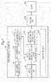
- Fig. 1 illustrates a functional configuration example of a data processing apparatus 100 according to the present embodiment.
- the data processing apparatus 100 is a computer. Further, an operation procedure of the data processing apparatus 100 is equivalent to a data processing method. Further, a program which realizes operation of the data processing apparatus 100 is equivalent to a data processing program.
- the data processing apparatus 100 generates pieces of device-relation data indicating relations between a plurality of devices 300, and displays the generated pieces of device-relation data.
- the device 300 is, for example, device placed in a factory.
- the data processing apparatus 100 can access each of the plurality of devices 300 via an outside tool 200.
- a data-model generation unit 101 generates data models. Details of the data model will be described later.
- a data conversion unit 102 converts the data models generated by the data-model generation unit 101 into data in a different format.
- the data conversion unit 102 converts the data models into data in an XML-format. Note that, the data converted by the data conversion unit 102 is referred to as conversion data.
- a conversion-data storage unit 107 stores the conversion data.
- a device designation unit 103 designates as a subject device, a device 300 among the plurality of devices 300 according to an instruction from a user of the data processing apparatus 100.
- a process performed by the device designation unit 103 is equivalent to a device designation process.
- a device-relation-data generation unit 104 acquires the conversion data from the conversion-data storage unit 107, and generates the plurality of pieces of device-relation data, using the conversion data. In each of the plurality of pieces of device-relation data, the plurality of devices 300 are written, and relations between the plurality of devices 300 are defined in definition forms which are different from each other.
- the device-relation-data generation unit 104 is assumed to generate the device-relation data indicating physical arrangement of the devices, the device-relation data indicating an electrical-connection relation between the devices, and the device-relation data indicating a network-connection relation between the devices.
- the device-relation data indicating the physical arrangement of the devices is referred to as physical-arrangement data.
- the device-relation data indicating the electrical-connection relation between the devices is referred to as electrical-connection relation data.
- the device-relation data indicating the network-connection relation between the devices is referred to as network-connection relation data.
- the device-relation-data generation unit 104 outputs to a displaying unit 106, the physical-arrangement data, the electrical-connection relation data, and the network-connection relation data which have been generated.
- the device-relation-data generation unit 104 extracts writing of the subject device in each piece of device-relation data. That is, the device-relation-data generation unit 104 specifies a position of the writing of the subject device in each of the physical-arrangement data, the electrical-connection relation data, and a network-connection relation. Then, the device-relation-data generation unit 104 notifies the displaying unit 106 of the position of the writing of the subject device in each of the physical-arrangement data, the electrical-connection relation data, and the network-connection relation which have been specified.
- the device-relation-data generation unit 1 04 generates state-value displaying data indicating state values of the device 300 acquired by an outside-tool cooperation unit 105 which will be described later, and outputs the generated state-value displaying data to the displaying unit 106.
- the device-relation-data generation unit 104 is equivalent to a device extraction unit. Further, a process performed by the device-relation-data generation unit 104 is equivalent to a device extraction process.
- the outside-tool cooperation unit 105 acquires the state values indicating states of each device 300 via the outside tool 200.
- the state values are, for example, an electric current value, a voltage value, an electric power value, and the like of the device 300.
- the outside-tool cooperation unit 105 outputs the state values acquired via the outside tool 200 to the device-relation-data generation unit 104.
- outside-tool cooperation unit 105 can output the pieces of device-relation data to the outside tool 200.
- the displaying unit 106 displays on a display device, the plurality of pieces of device-relation data output by the device-relation-data generation unit 104.
- the displaying unit 106 associates the pieces of writing of the subject device with each other over the plurality of pieces of device-relation data, when the positions of the pieces of writing of the subject device are notified of by the device-relation-data generation unit 104.
- the displaying unit 106 displays the state-value displaying data on the display device.
- a process performed by the displaying unit 106 is equivalent to a displaying process.
- Fig. 2 illustrates a hardware configuration example of the data processing apparatus 100 according to the present embodiment.
- the data processing apparatus 100 includes as pieces of hardware, a processor 901, a main storage device 902, an auxiliary storage device 903, a communication device 904, and an input/output device 905.
- the auxiliary storage device 903 stores programs which realize functions of the data-model generation unit 101, the data conversion unit 102, the device designation unit 103, the device-relation-data generation unit 104, the outside-tool cooperation unit 105, and the displaying unit 106.
- These programs are loaded from the auxiliary storage device 903 into the main storage device 902. Then, the processor 901 executes these programs, and performs operation of the data-model generation unit 101, the data conversion unit 102, the device designation unit 103, the device-relation-data generation unit 104, the outside-tool cooperation unit 105, and the displaying unit 106.
- Fig. 3 schematically illustrates a state where the processor 901 executes the programs which realize the functions of the data-model generation unit 101, the data conversion unit 102, the device designation unit 103, the device-relation-data generation unit 104, the outside-tool cooperation unit 105, and the displaying unit 106.
- the communication device 904 is used for performing communication with the outside tool 200.
- the input/output devices 905 are a keyboard, a mouse, a display device, and the like.
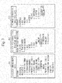
- Fig. 3 illustrates examples of the pieces of device-relation data.
- physical-arrangement data 301, electrical-connection relation data 302, and network-connection relation data 303 are generated as the pieces of device-relation data.
- the physical-arrangement data 301 indicates the physical arrangement in the factory.
- the physical-arrangement data 301 indicates the physical arrangement in the factory in a hierarchical structure.
- transformer1, transformer2, MDU-B, sequencer, motor, MELIPC, and EcoServer are the devices.
- the electrical-connection relation data 302 indicates the electrical-connection relation in the factory.
- the network-connection relation data 303 indicates the electrical-connection relation in the factory in a hierarchical structure.
- transformer1, transformer2, ACB1, ACB2, VCB1, VCB2, MDU-A, MDU-B, sequencer, motor, MELIPC, and EcoServer are the devices.
- the network-connection relation data 303 indicates the network-connection relation in the factory.
- the network-connection relation data 303 indicates the network-connection relation in the factory in a hierarchical structure.
- firewall Among elements indicated in the network-connection relation data 303, firewall, DMZ, router, PC, MELIPC, sequencer, motor, EcoServer, EcoMonitor, and MDU-B are the devices.
- MDU-B is emphatically displayed in each of the physical-arrangement data 301, the electrical-connection relation data 302, and the network-connection relation data 303. That is, the examples of Fig. 3 indicate an example where MDU-B has been designated by the device designation unit 103 as the subject device and the device-relation-data generation unit 104 has extracted the position of the writing of MDU-B in each of the physical-arrangement data 301, the electrical-connection relation data 302, and the network-connection relation data 303.
- the data processing apparatus 100 can display the same device (MDU-B) as the same device in the plurality of pieces of device-relation data.
- emphatic displaying is made by surrounding the subject device in a dotted line
- the emphatic displaying may be made by any method.
- each of the physical-arrangement data 301, the electrical-connection relation data 302, and the network-connection relation data 303 in Fig. 3 an example is illustrated in which there is one root node at a highest level in a tree. However, a plurality of root nodes may exist.
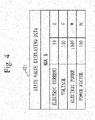
- Fig. 4 illustrates an example of the state-value displaying data according to the present embodiment.
- Fig. 4 indicates an electric current value, a voltage value, an electric power value, and a power factor value as the state values of MDU-B.
- Fig. 5 illustrates an example of a device-information input screen 501 according to the present embodiment.
- Fig. 5 illustrates the device-information input screen 501 for inputting device information of MDU-B in Fig. 3 .
- the displaying unit 106 displays the device-information input screen 501 illustrated in Fig. 5 on the display device.
- the user inputs the device information into the device-information input screen, using a mouse and a keyboard.
- the user inputs basic information, physical-arrangement information, electrical-connection information, and network-connection information into the device-information input screen 501.
- the user inputs a device ID, a device name, a name of a type of device, a profile, and a version as the basic information. Specifically, the user inputs the device ID into a field 510. Further, the user inputs the device name into a field 511. Further, the user inputs the name of the type of device into a field 512. Further, the user inputs the profile into a field 513. Further, the user inputs the version into a field 514.
- the user inputs a higher-level device name and an installation position as the physical-arrangement information. Specifically, the user inputs the higher-level device name into a field 515. Further, the user inputs the installation position into a field 516.
- the user inputs a higher-level device name, connection information (a connection line), and rated voltage/rated electric current as the electrical-connection relation information. Specifically, the user inputs the higher-level device name into a field 517. Further, the user inputs the connection information (the connection line) into fields 518. Further, the user inputs the rated voltage/rated electric current into fields 519.
- the user inputs a higher-level device name, a communication-scheme name, and a communication address as the network-connection information. Specifically, the user inputs the higher-level device name into a field 520. Further, the user inputs the communication-scheme name into a field 521. Further, the user inputs the communication address into a field 522.
- Fig. 5 illustrates the device-information input screen 501 for inputting the device information of MDU-B
- the user inputs necessary values into the device-information input screen 501 for each of the elements in Fig. 3 . Since higher-level devices do not exist for the highest-level elements in Fig. 3 , that is "factory" in the physical-arrangement data 301, "high-voltage receiving facility” in the electrical-connection relation data 302, and "Internet” in the network-connection relation data 303, the user does not input the higher-level devices for these elements.
- Values which have been input into the device-information input screen 501 are input into the data-model generation unit 101 by the pressing on the save button.
- the data-model generation unit 101 generates the data model for each element, using the values which have been input into the device-information input screen 501 of Fig. 5 .
- Fig. 6 illustrates an example of the data model generated by the data-model generation unit 101.
- Fig. 6 illustrates the example of the data model generated from the device-information input screen 501 of Fig. 5 . That is, Fig. 6 illustrates the data model of MDU-B.
- a basic-information node 601 is a node corresponding to the basic information on the device-information input screen 501.
- the values which have been input into the field 511, the field 512, the field 513, and the field 514 in Fig. 5 are set.
- a physical-arrangement information node 602 is a node corresponding to the physical-arrangement information on the device-information input screen 501. In the physical-arrangement information node 602, the values which have been input into the field 515 and the field 516 are set.
- An electrical-connection information node 603 is a node corresponding to the electrical-connection information on the device-information input screen 501.
- the values which have been input into the field 517, the fields 518, and the fields 519 are set.
- a network-connection information node 604 is a node corresponding to the network-connection relation information on the device-information input screen 501.
- the values which have been input into the field 520, the field 521, and the field 522 are set.
- Fig. 6 illustrates the data model of MDU-B
- the data-model generation unit 101 generates for each of the elements in Fig. 3 , a data model similar to the data model in Fig. 6 .
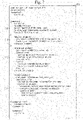
- Fig. 7 illustrates an example of conversion data 701 generated by the data conversion unit 102.
- Fig. 7 illustrates the example of the conversion data 701 obtained by converting the data models into an XML format.
- the conversion data 701 describes each of the elements indicated in Fig. 3 .
- Fig. 7 mainly indicates descriptions of MDU-B.
- a basic-information block 711 describes items indicated in the basic-information node 601.
- a physical-arrangement information block 712 describes items indicated in the physical-arrangement information node 602.
- An electrical-connection information block 713 describes items indicated in the electrical-connection information node 603.
- a network-connection information block 714 describes items indicated in the network-connection information node 604.
- the device-relation-data generation unit 104 analyzes the conversion data 701 illustrated in Fig. 7 , and generates the physical-arrangement data 301 from the physical-arrangement information block 712. Further, the device-relation-data generation unit 104 generates the electrical-connection relation data 302 from the electrical-connection information block 713. Further, the device-relation-data generation unit 104 generates the network-connection relation data 303 from the network-connection information block 714.
- the device-relation-data generation unit 104 repeats operation of extracting elements ("production line 1" and "second floor” in the example of Fig. 7 ) at immediately-upper layers from the physical-arrangement information block 712 in ascending order from an element at the lowest layer, and generates the physical-arrangement data 301. Also for the electrical-connection relation data 302, the device-relation-data generation unit 104 repeats operation of extracting elements at immediately-upper layers from the electrical-connection information block 713 in ascending order from an element at the lowest layer, and generates the electrical-connection relation data 302.
- the device-relation-data generation unit 104 repeats operation of extracting elements at immediately-upper layers from the network-connection information block 714 in ascending order from an element at the lowest layer, and generates the network-connection relation data 303.
- Fig. 8 illustrates operation procedures up to storage of the conversion data.
- Fig. 9 illustrates operation procedures of generating and displaying the pieces of device-relation data, emphatically displaying the subject device, and generating and displaying the state-value displaying data.
- step S801 in Fig. 8 the data-model generation unit 101 acquires the device information.
- the displaying unit 106 displays the device-information input screen 501 of Fig. 5 on the display device. Then, the data-model generation unit 101 acquires as the device information, the input value into each field on the device-information input screen 501 from the keyboard, the mouse, and the like.
- step S802 the data-model generation unit 101 generates the data model (the basic-information node 601, the physical-arrangement information node 602, and the electrical-connection information node 603) of Fig. 6 for each device based on the input values of the device-information input screen 501.
- the data-model generation unit 101 outputs the data model generated for each device to the data conversion unit 102.
- step S803 the data conversion unit 102 converts the data models into the conversion data, and generates the conversion data exemplified in Fig. 7 .
- the data conversion unit 102 integrates the data models of the devices, and further converts the integrated data model into the conversion data 701 exemplified in Fig. 7 .
- step S804 the data conversion unit 102 stores the conversion data in the conversion-data storage unit 107.
- step S902 the device-relation-data generation unit 104 acquires the conversion data from the conversion-data storage unit 107, and analyzes the conversion data to generate the pieces of device-relation data. That is, the device-relation-data generation unit 104 generates the physical-arrangement data 301, the electrical-connection relation data 302, and the network-connection relation data 303 in Fig. 3 .
- the device-relation-data generation unit 104 generates the physical-arrangement data 301 from the physical-arrangement information block 712. Further, the device-relation-data generation unit 104 generates the electrical-connection relation data 302 from the electrical-connection information block 713. Further, the device-relation-data generation unit 104 generates the network-connection relation data 303 from the network-connection information block 714.
- step S903 the displaying unit 106 displays the physical-arrangement data 301, the electrical-connection relation data 302, and the network-connection relation data 303 on the display device.
- the emphatic displaying 305 for MDU-B has not been performed.
- the device-relation-data generation unit 104 extracts the writing of the subject device from each piece of device-relation data.
- the device designation unit 103 designates MDU-B as the subject device.
- the device designation unit 103 notifies the device-relation-data generation unit 104 of MDU-B as the subject device.
- the device-relation-data generation unit 104 scans each of the electrical-connection relation data 302 and the network-connection relation data 303 for the same character string as MDU-B, performing, for example, character recognition, and extracts the positions of the pieces of writing of MDU-B in the electrical-connection relation data 302 and the network-connection relation data 303.
- the device-relation-data generation unit 104 notifies the displaying unit 106 of the extracted positions of the pieces of writing of MDU-B in the electrical-connection relation data 302 and the network-connection relation data 303, and a position (the position of the writing of MDU-B in the physical-arrangement data 301) clicked on by the user through the mouse.
- step S906 the displaying unit 106 displays the pieces of writing of the subject device in the plurality of pieces of relation data, associating the pieces of writing with each other. That is, the displaying unit 106 displays emphatically in each of the physical-arrangement data 301, the electrical-connection relation data 302 and the network-connection relation data 303, the position of the writing notified of by the device-relation-data generation unit 104.
- step S908 the outside-tool cooperation unit 105 accesses the corresponding device 300 via the outside tool 200, and acquires the state values from the device 300.
- the outside-tool cooperation unit 105 notifies the device-relation-data generation unit 104 of the acquired state values.
- step S909 the device-relation-data generation unit 104 generates the state-value displaying data indicating the state values which have been notified of by the outside-tool cooperation unit 105, and the displaying unit 106 displays the state-value displaying data on the display device.
- the same device included and coexisted in the plurality of pieces of device-relation data can be displayed as the same device.
- the user can recognize the same device included and coexisted in the plurality of pieces of device-relation data as the same device. Further, since the user can recognize the same device, the user can correctly understand the physical arrangement, the electrical-connection relation, and the network-connection relation in the factory.
- the physical-arrangement data 301, the electrical-connection relation data 302, and the network-connection relation data 303 have been indicated above as the examples of the pieces of device-relation data. However, the pieces of device-relation data are not limited to these.
- the pieces of device-relation data are presented to the user of the data processing apparatus 100.
- the outside-tool cooperation unit 105 can acquire the pieces of device-relation data from the device-relation-data generation unit 104, and output the acquired pieces of device-relation data to the outside tool 200.
- the pieces of device-relation data are not limited to the data processing apparatus 100.
- Fig. 10 illustrates an example of the conversion data according to the present embodiment.
- the data conversion unit 102 converts the integrated data model into conversion data 1001 in a CSV format.
- Operation of the data processing apparatus 100 is the same as that indicated in the first embodiment except that the conversion data 1001 in the CSV format in Fig. 10 is used in place of the conversion data 701 in the XML format in Fig. 7 .
- one of these two embodiments may be partially implemented.
- the processor 901 illustrated in Fig. 3 is an IC (Integrated Circuit) that performs processing.
- the processor 901 is a CPU (Central Processing Unit), a DSP (Digital Signal Processor), or the like.
- the main storage device 902 illustrated in Fig. 3 is a RAM (Random Access Memory).
- the auxiliary storage device 903 illustrated in Fig. 3 is a ROM (Read Only Memory), a flash memory, an HDD (Dard Disk Drive), or the like.
- the communication device 904 illustrated in Fig. 3 is an electronic circuit that executes a communication process of data.
- the communication device 904 is, for example, a communication chip or an NIC (Network Interface Card).
- auxiliary storage device 903 also stores an OS (Operating System). Then, at least a part of the OS is executed by the processor 901.
- OS Operating System
- the processor 901 While executing at least the part of the OS, the processor 901 executes the programs which realize the functions of the data-model generation unit 101, the data conversion unit 102, the device designation unit 103, the device-relation-data generation unit 104, and the outside-tool cooperation unit 105.
- processor 901 By the processor 901 executing the OS, task management, memory management, file management, communication control, and the like are performed.
- At least one of information, data, a signal value, and a variable value that indicate results of processes of the data-model generation unit 101, the data conversion unit 102, the device designation unit 103, the device-relation-data generation unit 104, and the outside-tool cooperation unit 105 is stored in at least one of the main storage device 902, the auxiliary storage device 903, and a register and a cash memory in the processor 901.
- the programs which realize the functions of the data-model generation unit 101, the data conversion unit 102, the device designation unit 103, the device-relation-data generation unit 104, and the outside-tool cooperation unit 105 may be stored in a portable recording medium such as a magnetic disk, a flexible disk, an optical disc, a compact disc, a Blu-ray (registered trademark) disc, or a DVD. Then, the portable recording medium storing the programs which realize the functions of the data-model generation unit 101, the data conversion unit 102, the device designation unit 103, the device-relation-data generation unit 104, and the outside-tool cooperation unit 105 may be distributed.
- a portable recording medium such as a magnetic disk, a flexible disk, an optical disc, a compact disc, a Blu-ray (registered trademark) disc, or a DVD.
- unit of the data-model generation unit 101, the data conversion unit 102, the device designation unit 103, the device-relation-data generation unit 104, and the outside-tool cooperation unit 105 may be read as “circuit”, “step”, “procedure”, or "process”.
- the data processing apparatus 100 may be realized by a processing circuit.
- the processing circuit is, for example, a logic IC (Integrated Circuit), a GA (Gate Array), an ASIC (Application Specific Integrated Circuit), or an FPGA (Field-Programmable Gate Array).
- each of the data-model generation unit 101, the data conversion unit 102, the device designation unit 103, the device-relation-data generation unit 104, and the outside-tool cooperation unit 105 is realized as a part of the processing circuit.
- processing circuitry a superordinate concept of the processor and the processing circuit.
- each of the processor and the processing circuit is a specific example of the "processing circuitry”.
Landscapes
- Engineering & Computer Science (AREA)
- Business, Economics & Management (AREA)
- Human Resources & Organizations (AREA)
- Economics (AREA)
- Physics & Mathematics (AREA)
- General Physics & Mathematics (AREA)
- Strategic Management (AREA)
- Manufacturing & Machinery (AREA)
- Quality & Reliability (AREA)
- Entrepreneurship & Innovation (AREA)
- Theoretical Computer Science (AREA)
- General Business, Economics & Management (AREA)
- Marketing (AREA)
- Tourism & Hospitality (AREA)
- Automation & Control Theory (AREA)
- Primary Health Care (AREA)
- General Health & Medical Sciences (AREA)
- Health & Medical Sciences (AREA)
- Development Economics (AREA)
- Educational Administration (AREA)
- General Engineering & Computer Science (AREA)
- Game Theory and Decision Science (AREA)
- Operations Research (AREA)
- User Interface Of Digital Computer (AREA)
- Information Retrieval, Db Structures And Fs Structures Therefor (AREA)
- Management, Administration, Business Operations System, And Electronic Commerce (AREA)
Abstract
Description
- The present disclosure relates to a technique of managing devices.
- Conventionally, as a management method of devices and the like in a factory, a method has been adopted of managing pieces of information such as physical arrangement of the devices and a relation of electrical-connection between the devices.
- For example,
Patent Literature 1 manages devices in a factory as data models, and displays a plurality of pieces of device-relation data indicating relations between the devices in a plurality of definition forms.Patent Literature 1 displays, for example, device-relation data indicating physical arrangement of the devices and device-relation data indicating an electrical-connection relation between the devices. - Patent Literature 1:
JP2004-013197A - A technique of
Patent Literature 1 can display the relations between the devices in the plurality of pieces of device-relation data of the plurality of definition forms. Although the same device is included and coexisted in the plurality of pieces of device-relation data, the technique ofPatent Literature 1 has a problem that a user can not recognize the same device as the same device. - One of the main objects of the present disclosure is to solve the above-described problem. More specifically, the present disclosure mainly aims to enable recognizing the same device included and coexisted in a plurality of pieces of device-relation data.
- A data processing apparatus according to the present disclosure includes:
- a displaying unit to display a plurality of pieces of device-relation data in each of which a plurality of devices are written and a relation between the plurality of devices is defined in a different definition form from each other;
- a device designation unit to designate as a subject device, a device among the plurality of devices; and
- a device extraction unit to extract writing of the subject device for each piece of device-relation data, and
- wherein the displaying unit associates the pieces of writing of the subject device with each other over the plurality of pieces of device-relation data.
- According to the present disclosure, it is possible to recognize the same device included and coexisted in a plurality of pieces of device-relation data.
-
-
Fig. 1 is a diagram illustrating a functional configuration example of a data processing apparatus according to a first embodiment. -
Fig. 2 is a diagram illustrating a hardware configuration example of the data processing apparatus according to the first embodiment. -
Fig. 3 is a diagram illustrating examples of pieces of device-relation data according to the first embodiment. -
Fig. 4 is a diagram illustrating an example of state-value displaying data according to the first embodiment. -
Fig. 5 is a diagram illustrating an example of a device-information input screen according to the first embodiment. -
Fig. 6 is a diagram illustrating an example of a data model according to the first embodiment. -
Fig. 7 is a diagram illustrating an example of conversion data in an XML-format according to the first embodiment. -
Fig. 8 is a flowchart illustrating an operation example of the data processing apparatus according to the first embodiment. -
Fig. 9 is a flowchart illustrating an operation example of the data processing apparatus according to the first embodiment. -
Fig. 10 is a diagram illustrating an example of conversion data in a CSV-format according to the first embodiment. - Hereinafter, embodiments will be described with reference to the drawings. In the following description of the embodiments and the drawings, parts assigned by the same reference numerals indicate the same parts or corresponding parts.
-
Fig. 1 illustrates a functional configuration example of adata processing apparatus 100 according to the present embodiment. - The
data processing apparatus 100 is a computer. Further, an operation procedure of thedata processing apparatus 100 is equivalent to a data processing method. Further, a program which realizes operation of thedata processing apparatus 100 is equivalent to a data processing program. - The
data processing apparatus 100 generates pieces of device-relation data indicating relations between a plurality ofdevices 300, and displays the generated pieces of device-relation data. Thedevice 300 is, for example, device placed in a factory. - Further, the
data processing apparatus 100 can access each of the plurality ofdevices 300 via anoutside tool 200. - A data-
model generation unit 101 generates data models. Details of the data model will be described later. - A
data conversion unit 102 converts the data models generated by the data-model generation unit 101 into data in a different format. In the present embodiment, thedata conversion unit 102 converts the data models into data in an XML-format. Note that, the data converted by thedata conversion unit 102 is referred to as conversion data. - A conversion-data storage unit 107 stores the conversion data.
- A
device designation unit 103 designates as a subject device, adevice 300 among the plurality ofdevices 300 according to an instruction from a user of thedata processing apparatus 100. - A process performed by the
device designation unit 103 is equivalent to a device designation process. - A device-relation-
data generation unit 104 acquires the conversion data from the conversion-data storage unit 107, and generates the plurality of pieces of device-relation data, using the conversion data. In each of the plurality of pieces of device-relation data, the plurality ofdevices 300 are written, and relations between the plurality ofdevices 300 are defined in definition forms which are different from each other. In the present embodiment, as an example, the device-relation-data generation unit 104 is assumed to generate the device-relation data indicating physical arrangement of the devices, the device-relation data indicating an electrical-connection relation between the devices, and the device-relation data indicating a network-connection relation between the devices. Hereinafter, the device-relation data indicating the physical arrangement of the devices is referred to as physical-arrangement data. Further, the device-relation data indicating the electrical-connection relation between the devices is referred to as electrical-connection relation data. Further, the device-relation data indicating the network-connection relation between the devices is referred to as network-connection relation data. - Then, the device-relation-
data generation unit 104 outputs to a displayingunit 106, the physical-arrangement data, the electrical-connection relation data, and the network-connection relation data which have been generated. - Further, when the subject device is designated by the
device designation unit 103, the device-relation-data generation unit 104 extracts writing of the subject device in each piece of device-relation data. That is, the device-relation-data generation unit 104 specifies a position of the writing of the subject device in each of the physical-arrangement data, the electrical-connection relation data, and a network-connection relation. Then, the device-relation-data generation unit 104 notifies the displayingunit 106 of the position of the writing of the subject device in each of the physical-arrangement data, the electrical-connection relation data, and the network-connection relation which have been specified. - Further, the device-relation-
data generation unit 1 04 generates state-value displaying data indicating state values of thedevice 300 acquired by an outside-tool cooperation unit 105 which will be described later, and outputs the generated state-value displaying data to the displayingunit 106. - The device-relation-
data generation unit 104 is equivalent to a device extraction unit. Further, a process performed by the device-relation-data generation unit 104 is equivalent to a device extraction process. - The outside-
tool cooperation unit 105 acquires the state values indicating states of eachdevice 300 via theoutside tool 200. - The state values are, for example, an electric current value, a voltage value, an electric power value, and the like of the
device 300. - The outside-
tool cooperation unit 105 outputs the state values acquired via theoutside tool 200 to the device-relation-data generation unit 104. - Also, the outside-
tool cooperation unit 105 can output the pieces of device-relation data to theoutside tool 200. - The displaying
unit 106 displays on a display device, the plurality of pieces of device-relation data output by the device-relation-data generation unit 104. - Further, the displaying
unit 106 associates the pieces of writing of the subject device with each other over the plurality of pieces of device-relation data, when the positions of the pieces of writing of the subject device are notified of by the device-relation-data generation unit 104. - Further, when the state-value displaying data is output by the device-relation-
data generation unit 104, the displayingunit 106 displays the state-value displaying data on the display device. - A process performed by the displaying
unit 106 is equivalent to a displaying process. -
Fig. 2 illustrates a hardware configuration example of thedata processing apparatus 100 according to the present embodiment. - The
data processing apparatus 100 includes as pieces of hardware, aprocessor 901, amain storage device 902, anauxiliary storage device 903, acommunication device 904, and an input/output device 905. - The
auxiliary storage device 903 stores programs which realize functions of the data-model generation unit 101, thedata conversion unit 102, thedevice designation unit 103, the device-relation-data generation unit 104, the outside-tool cooperation unit 105, and the displayingunit 106. - These programs are loaded from the
auxiliary storage device 903 into themain storage device 902. Then, theprocessor 901 executes these programs, and performs operation of the data-model generation unit 101, thedata conversion unit 102, thedevice designation unit 103, the device-relation-data generation unit 104, the outside-tool cooperation unit 105, and the displayingunit 106. -
Fig. 3 schematically illustrates a state where theprocessor 901 executes the programs which realize the functions of the data-model generation unit 101, thedata conversion unit 102, thedevice designation unit 103, the device-relation-data generation unit 104, the outside-tool cooperation unit 105, and the displayingunit 106. - The
communication device 904 is used for performing communication with theoutside tool 200. - The input/
output devices 905 are a keyboard, a mouse, a display device, and the like. -
Fig. 3 illustrates examples of the pieces of device-relation data. - As described above, in the present embodiment, physical-
arrangement data 301, electrical-connection relation data 302, and network-connection relation data 303 are generated as the pieces of device-relation data. - The physical-
arrangement data 301 indicates the physical arrangement in the factory. The physical-arrangement data 301 indicates the physical arrangement in the factory in a hierarchical structure. - Among elements indicated in the physical-
arrangement data 301, transformer1, transformer2, MDU-B, sequencer, motor, MELIPC, and EcoServer are the devices. - The electrical-
connection relation data 302 indicates the electrical-connection relation in the factory. The network-connection relation data 303 indicates the electrical-connection relation in the factory in a hierarchical structure. - Among elements indicated in the electrical-
connection relation data 302, transformer1, transformer2, ACB1, ACB2, VCB1, VCB2, MDU-A, MDU-B, sequencer, motor, MELIPC, and EcoServer are the devices. - The network-
connection relation data 303 indicates the network-connection relation in the factory. The network-connection relation data 303 indicates the network-connection relation in the factory in a hierarchical structure. - Among elements indicated in the network-
connection relation data 303, firewall, DMZ, router, PC, MELIPC, sequencer, motor, EcoServer, EcoMonitor, and MDU-B are the devices. - In the examples of
Fig. 3 , as indicated byreference numerals 305, MDU-B is emphatically displayed in each of the physical-arrangement data 301, the electrical-connection relation data 302, and the network-connection relation data 303. That is, the examples ofFig. 3 indicate an example where MDU-B has been designated by thedevice designation unit 103 as the subject device and the device-relation-data generation unit 104 has extracted the position of the writing of MDU-B in each of the physical-arrangement data 301, the electrical-connection relation data 302, and the network-connection relation data 303. - As described above, the
data processing apparatus 100 according to the present embodiment can display the same device (MDU-B) as the same device in the plurality of pieces of device-relation data. - Note that, although in the examples of
Fig. 3 , emphatic displaying is made by surrounding the subject device in a dotted line, the emphatic displaying may be made by any method. For example, it is conceivable to display character strings of the subject device in different color from color of character strings of the other devices, to display backgrounds of areas of the subject device in different color from color of backgrounds of areas of the other devices, and so on. - In each of the physical-
arrangement data 301, the electrical-connection relation data 302, and the network-connection relation data 303 inFig. 3 , an example is illustrated in which there is one root node at a highest level in a tree. However, a plurality of root nodes may exist. -
Fig. 4 illustrates an example of the state-value displaying data according to the present embodiment. - The example of
Fig. 4 indicates an electric current value, a voltage value, an electric power value, and a power factor value as the state values of MDU-B. -
Fig. 5 illustrates an example of a device-information input screen 501 according to the present embodiment. -
Fig. 5 illustrates the device-information input screen 501 for inputting device information of MDU-B inFig. 3 . - The displaying
unit 106 displays the device-information input screen 501 illustrated inFig. 5 on the display device. - The user inputs the device information into the device-information input screen, using a mouse and a keyboard.
- The user inputs basic information, physical-arrangement information, electrical-connection information, and network-connection information into the device-
information input screen 501. - The user inputs a device ID, a device name, a name of a type of device, a profile, and a version as the basic information. Specifically, the user inputs the device ID into a
field 510. Further, the user inputs the device name into afield 511. Further, the user inputs the name of the type of device into afield 512. Further, the user inputs the profile into afield 513. Further, the user inputs the version into afield 514. - The user inputs a higher-level device name and an installation position as the physical-arrangement information. Specifically, the user inputs the higher-level device name into a
field 515. Further, the user inputs the installation position into afield 516. - The user inputs a higher-level device name, connection information (a connection line), and rated voltage/rated electric current as the electrical-connection relation information. Specifically, the user inputs the higher-level device name into a
field 517. Further, the user inputs the connection information (the connection line) intofields 518. Further, the user inputs the rated voltage/rated electric current intofields 519. - The user inputs a higher-level device name, a communication-scheme name, and a communication address as the network-connection information. Specifically, the user inputs the higher-level device name into a
field 520. Further, the user inputs the communication-scheme name into afield 521. Further, the user inputs the communication address into afield 522. - Although
Fig. 5 illustrates the device-information input screen 501 for inputting the device information of MDU-B, the user inputs necessary values into the device-information input screen 501 for each of the elements inFig. 3 . Since higher-level devices do not exist for the highest-level elements inFig. 3 , that is "factory" in the physical-arrangement data 301, "high-voltage receiving facility" in the electrical-connection relation data 302, and "Internet" in the network-connection relation data 303, the user does not input the higher-level devices for these elements. - The user presses a save button after completing the input into the device-
information input screen 501. Values which have been input into the device-information input screen 501 are input into the data-model generation unit 101 by the pressing on the save button. - The data-
model generation unit 101 generates the data model for each element, using the values which have been input into the device-information input screen 501 ofFig. 5 . -
Fig. 6 illustrates an example of the data model generated by the data-model generation unit 101. - More specifically,
Fig. 6 illustrates the example of the data model generated from the device-information input screen 501 ofFig. 5 . That is,Fig. 6 illustrates the data model of MDU-B. - A basic-
information node 601 is a node corresponding to the basic information on the device-information input screen 501. In the basic-information node 601, the values which have been input into thefield 511, thefield 512, thefield 513, and thefield 514 inFig. 5 are set. - A physical-
arrangement information node 602 is a node corresponding to the physical-arrangement information on the device-information input screen 501. In the physical-arrangement information node 602, the values which have been input into thefield 515 and thefield 516 are set. - An electrical-
connection information node 603 is a node corresponding to the electrical-connection information on the device-information input screen 501. In the electrical-connection information node 603, the values which have been input into thefield 517, thefields 518, and thefields 519 are set. - A network-
connection information node 604 is a node corresponding to the network-connection relation information on the device-information input screen 501. In the network-connection information node 604, the values which have been input into thefield 520, thefield 521, and thefield 522 are set. - Although
Fig. 6 illustrates the data model of MDU-B, the data-model generation unit 101 generates for each of the elements inFig. 3 , a data model similar to the data model inFig. 6 . -
Fig. 7 illustrates an example ofconversion data 701 generated by thedata conversion unit 102.Fig. 7 illustrates the example of theconversion data 701 obtained by converting the data models into an XML format. Theconversion data 701 describes each of the elements indicated inFig. 3 .Fig. 7 mainly indicates descriptions of MDU-B. - A basic-
information block 711 describes items indicated in the basic-information node 601. - A physical-arrangement information block 712 describes items indicated in the physical-
arrangement information node 602. - An electrical-connection information block 713 describes items indicated in the electrical-
connection information node 603. - A network-connection information block 714 describes items indicated in the network-
connection information node 604. - The same configurations are applied to the devices other than MDU-B.
- The device-relation-
data generation unit 104 analyzes theconversion data 701 illustrated inFig. 7 , and generates the physical-arrangement data 301 from the physical-arrangement information block 712. Further, the device-relation-data generation unit 104 generates the electrical-connection relation data 302 from the electrical-connection information block 713. Further, the device-relation-data generation unit 104 generates the network-connection relation data 303 from the network-connection information block 714. - More specifically, the device-relation-
data generation unit 104 repeats operation of extracting elements ("production line 1" and "second floor" in the example ofFig. 7 ) at immediately-upper layers from the physical-arrangement information block 712 in ascending order from an element at the lowest layer, and generates the physical-arrangement data 301. Also for the electrical-connection relation data 302, the device-relation-data generation unit 104 repeats operation of extracting elements at immediately-upper layers from the electrical-connection information block 713 in ascending order from an element at the lowest layer, and generates the electrical-connection relation data 302. Further, also for the network-connection relation data 303, the device-relation-data generation unit 104 repeats operation of extracting elements at immediately-upper layers from the network-connection information block 714 in ascending order from an element at the lowest layer, and generates the network-connection relation data 303. - With reference to
Figs. 8 and9 , operation of thedata processing apparatus 100 according to the present embodiment will be described. -
Fig. 8 illustrates operation procedures up to storage of the conversion data. -
Fig. 9 illustrates operation procedures of generating and displaying the pieces of device-relation data, emphatically displaying the subject device, and generating and displaying the state-value displaying data. - In step S801 in
Fig. 8 , the data-model generation unit 101 acquires the device information. - More specifically, the displaying
unit 106 displays the device-information input screen 501 ofFig. 5 on the display device. Then, the data-model generation unit 101 acquires as the device information, the input value into each field on the device-information input screen 501 from the keyboard, the mouse, and the like. - Next, in step S802, the data-
model generation unit 101 generates the data model (the basic-information node 601, the physical-arrangement information node 602, and the electrical-connection information node 603) ofFig. 6 for each device based on the input values of the device-information input screen 501. - The data-
model generation unit 101 outputs the data model generated for each device to thedata conversion unit 102. - Next, in step S803, the
data conversion unit 102 converts the data models into the conversion data, and generates the conversion data exemplified inFig. 7 . - More specifically, the
data conversion unit 102 integrates the data models of the devices, and further converts the integrated data model into theconversion data 701 exemplified inFig. 7 . - Then, in step S804, the
data conversion unit 102 stores the conversion data in the conversion-data storage unit 107. - In
Fig. 9 , if the user requests displaying of the pieces of device-relation data (YES in step S901), in step S902, the device-relation-data generation unit 104 acquires the conversion data from the conversion-data storage unit 107, and analyzes the conversion data to generate the pieces of device-relation data. That is, the device-relation-data generation unit 104 generates the physical-arrangement data 301, the electrical-connection relation data 302, and the network-connection relation data 303 inFig. 3 . - As described above, the device-relation-
data generation unit 104 generates the physical-arrangement data 301 from the physical-arrangement information block 712. Further, the device-relation-data generation unit 104 generates the electrical-connection relation data 302 from the electrical-connection information block 713. Further, the device-relation-data generation unit 104 generates the network-connection relation data 303 from the network-connection information block 714. - Then, in step S903, the displaying
unit 106 displays the physical-arrangement data 301, the electrical-connection relation data 302, and the network-connection relation data 303 on the display device. In this step, the emphatic displaying 305 for MDU-B has not been performed. - Next, when the
device designation unit 103 designates the subject device, triggered by an instruction from the user (YES in step S904), the device-relation-data generation unit 104 extracts the writing of the subject device from each piece of device-relation data. - For example, it is assumed that the user has clicked by the mouse on MDU-B indicated in the physical-
arrangement data 301. Thereby, thedevice designation unit 103 designates MDU-B as the subject device. Thedevice designation unit 103 notifies the device-relation-data generation unit 104 of MDU-B as the subject device. - The device-relation-
data generation unit 104 scans each of the electrical-connection relation data 302 and the network-connection relation data 303 for the same character string as MDU-B, performing, for example, character recognition, and extracts the positions of the pieces of writing of MDU-B in the electrical-connection relation data 302 and the network-connection relation data 303. - Then, the device-relation-
data generation unit 104 notifies the displayingunit 106 of the extracted positions of the pieces of writing of MDU-B in the electrical-connection relation data 302 and the network-connection relation data 303, and a position (the position of the writing of MDU-B in the physical-arrangement data 301) clicked on by the user through the mouse. - Next, in step S906, the displaying
unit 106 displays the pieces of writing of the subject device in the plurality of pieces of relation data, associating the pieces of writing with each other. That is, the displayingunit 106 displays emphatically in each of the physical-arrangement data 301, the electrical-connection relation data 302 and the network-connection relation data 303, the position of the writing notified of by the device-relation-data generation unit 104. - Next, if the user requests displaying of the state values of any device (YES in step S907), in step S908, the outside-
tool cooperation unit 105 accesses thecorresponding device 300 via theoutside tool 200, and acquires the state values from thedevice 300. - The outside-
tool cooperation unit 105 notifies the device-relation-data generation unit 104 of the acquired state values. - In step S909, the device-relation-
data generation unit 104 generates the state-value displaying data indicating the state values which have been notified of by the outside-tool cooperation unit 105, and the displayingunit 106 displays the state-value displaying data on the display device. - As described above, according to the present embodiment, the same device included and coexisted in the plurality of pieces of device-relation data can be displayed as the same device.
- Thereby, the user can recognize the same device included and coexisted in the plurality of pieces of device-relation data as the same device. Further, since the user can recognize the same device, the user can correctly understand the physical arrangement, the electrical-connection relation, and the network-connection relation in the factory.
- Further, according to the present embodiment, since current state values of the device are displayed, the user can comprehend a current state of the device.
- The physical-
arrangement data 301, the electrical-connection relation data 302, and the network-connection relation data 303 have been indicated above as the examples of the pieces of device-relation data. However, the pieces of device-relation data are not limited to these. - Further, mainly an example has been described above in which the pieces of device-relation data are presented to the user of the
data processing apparatus 100. However, it is possible to present the pieces of device-relation data to the outside of thedata processing apparatus 100. Specifically, if there is a request from theoutside tool 200, the outside-tool cooperation unit 105 can acquire the pieces of device-relation data from the device-relation-data generation unit 104, and output the acquired pieces of device-relation data to theoutside tool 200. Thereby, it is possible to refer to the pieces of device-relation data outside thedata processing apparatus 100. - In the present embodiment, mainly matters different from the first embodiment will be described.
- Note that, matters not described below are the same as those in the first embodiment.
-
Fig. 10 illustrates an example of the conversion data according to the present embodiment. - In the present embodiment, the
data conversion unit 102 converts the integrated data model intoconversion data 1001 in a CSV format. - Contents described in the
conversion data 1001 in the CSV format inFig. 10 are the same as contents described in theconversion data 701 in the XML format inFig. 7 . - Operation of the
data processing apparatus 100 is the same as that indicated in the first embodiment except that theconversion data 1001 in the CSV format inFig. 10 is used in place of theconversion data 701 in the XML format inFig. 7 . - Although the first and second embodiments have been described above, these two embodiments may be combined and implemented.
- Alternatively, one of these two embodiments may be partially implemented.
- Alternatively, these two embodiments may be partially combined and implemented.
- Further, the configurations and the procedures described in these two embodiments may be modified as necessary.
- Finally, supplementary descriptions of the hardware configuration of the
data processing apparatus 100 will be given. - The
processor 901 illustrated inFig. 3 is an IC (Integrated Circuit) that performs processing. - The
processor 901 is a CPU (Central Processing Unit), a DSP (Digital Signal Processor), or the like. - The
main storage device 902 illustrated inFig. 3 is a RAM (Random Access Memory). - The
auxiliary storage device 903 illustrated inFig. 3 is a ROM (Read Only Memory), a flash memory, an HDD (Dard Disk Drive), or the like. - The
communication device 904 illustrated inFig. 3 is an electronic circuit that executes a communication process of data. - The
communication device 904 is, for example, a communication chip or an NIC (Network Interface Card). - Further, the
auxiliary storage device 903 also stores an OS (Operating System). Then, at least a part of the OS is executed by theprocessor 901. - While executing at least the part of the OS, the
processor 901 executes the programs which realize the functions of the data-model generation unit 101, thedata conversion unit 102, thedevice designation unit 103, the device-relation-data generation unit 104, and the outside-tool cooperation unit 105. - By the
processor 901 executing the OS, task management, memory management, file management, communication control, and the like are performed. - Further, at least one of information, data, a signal value, and a variable value that indicate results of processes of the data-
model generation unit 101, thedata conversion unit 102, thedevice designation unit 103, the device-relation-data generation unit 104, and the outside-tool cooperation unit 105 is stored in at least one of themain storage device 902, theauxiliary storage device 903, and a register and a cash memory in theprocessor 901. - Further, the programs which realize the functions of the data-
model generation unit 101, thedata conversion unit 102, thedevice designation unit 103, the device-relation-data generation unit 104, and the outside-tool cooperation unit 105 may be stored in a portable recording medium such as a magnetic disk, a flexible disk, an optical disc, a compact disc, a Blu-ray (registered trademark) disc, or a DVD. Then, the portable recording medium storing the programs which realize the functions of the data-model generation unit 101, thedata conversion unit 102, thedevice designation unit 103, the device-relation-data generation unit 104, and the outside-tool cooperation unit 105 may be distributed. - Further, "unit" of the data-
model generation unit 101, thedata conversion unit 102, thedevice designation unit 103, the device-relation-data generation unit 104, and the outside-tool cooperation unit 105 may be read as "circuit", "step", "procedure", or "process". - Further, the
data processing apparatus 100 may be realized by a processing circuit. The processing circuit is, for example, a logic IC (Integrated Circuit), a GA (Gate Array), an ASIC (Application Specific Integrated Circuit), or an FPGA (Field-Programmable Gate Array). - In this case, each of the data-
model generation unit 101, thedata conversion unit 102, thedevice designation unit 103, the device-relation-data generation unit 104, and the outside-tool cooperation unit 105 is realized as a part of the processing circuit. - Note that, in the present specification, a superordinate concept of the processor and the processing circuit is referred to as "processing circuitry".
- That is, each of the processor and the processing circuit is a specific example of the "processing circuitry".
- 100: data processing apparatus, 101: data-model generation unit, 102: data conversion unit, 103: device designation unit, 104: device-relation-data generation unit, 105: outside-tool cooperation unit, 106: displaying unit, 107: conversion-data storage unit, 200: outside tool, 300: device, 301: physical-arrangement data, 302: electrical-connection relation data, 303: network-connection relation data, 401: state-value displaying data, 501: device-information input screen, 601: basic-information node, 602: physical-arrangement information node, 603: electrical-connection information node, 604: network-connection information node, 701: conversion data, 711: basic-information block, 712: physical-arrangement information block, 713: electrical-connection information block, 714: network-connection information block, 901: processor, 902: main storage device, 903: auxiliary storage device, 904: communication device, 905: input/output device, 1001: conversion data.
Claims (6)
- A data processing apparatus comprising:a displaying unit to display a plurality of pieces of device-relation data in each of which a plurality of devices are written and a relation between the plurality of devices is defined in a different definition form from each other;a device designation unit to designate as a subject device, a device among the plurality of devices; anda device extraction unit to extract writing of the subject device for each piece of device-relation data, andwherein the displaying unit associates the pieces of writing of the subject device with each other over the plurality of pieces of device-relation data.
- The data processing apparatus according to claim 1, wherein
the displaying unit emphasizes the pieces of writing of the subject device more than pieces of writing of the other devices in the plurality of pieces of device-relation data. - The data processing apparatus according to claim 1 further comprisinga state-value acquisition unit to acquire a state value indicating a state of the subject device, andwherein the displaying unit displays the acquired state value of the subject device.
- The data processing apparatus according to claim 1, wherein
the displaying unit displays three pieces of device-relation data in which the relation between the plurality of devices is defined by physical arrangement, an electrical-connection relation, and a network-connection relation. - A data processing method by a computer which displays a plurality of pieces of device-relation data in each of which a plurality of devices are written and a relation between the plurality of devices is defined in a different definition form from each other, the data processing method comprising:designating as a subject device, a device among the plurality of devices;extracting writing of the subject device for each piece of device-relation data; andassociating the pieces of writing of the subject device with each other over the plurality of pieces of device-relation data.
- A data processing program which causes
a computer which displays a plurality of pieces of device-relation data in each of which a plurality of devices are written and a relation between the plurality of devices is defined in a different definition form from each other, to execute:a device designation process of designating as a subject device, a device among the plurality of devices;a device extraction process of extracting writing of the subject device for each piece of device-relation data; anda displaying process of associating the pieces of writing of the subject device with each other over the plurality of pieces of device-relation data.
Applications Claiming Priority (1)
| Application Number | Priority Date | Filing Date | Title |
|---|---|---|---|
| PCT/JP2020/004513 WO2021156998A1 (en) | 2020-02-06 | 2020-02-06 | Data processing apparatus, data processing method, and data processing program |
Publications (3)
| Publication Number | Publication Date |
|---|---|
| EP4083880A1 true EP4083880A1 (en) | 2022-11-02 |
| EP4083880A4 EP4083880A4 (en) | 2023-01-11 |
| EP4083880B1 EP4083880B1 (en) | 2024-08-07 |
Family
ID=77200815
Family Applications (1)
| Application Number | Title | Priority Date | Filing Date |
|---|---|---|---|
| EP20917828.4A Active EP4083880B1 (en) | 2020-02-06 | 2020-02-06 | Data processing apparatus, data processing method, and data processing program |
Country Status (4)
| Country | Link |
|---|---|
| EP (1) | EP4083880B1 (en) |
| JP (1) | JP7023432B2 (en) |
| CN (1) | CN115023714B (en) |
| WO (1) | WO2021156998A1 (en) |
Family Cites Families (16)
| Publication number | Priority date | Publication date | Assignee | Title |
|---|---|---|---|---|
| JPH0836592A (en) * | 1994-07-22 | 1996-02-06 | Hitachi Ltd | Computer system configuration management support method and apparatus |
| JP2004013197A (en) | 2002-06-03 | 2004-01-15 | Sopac System:Kk | Facility information management system for factory |
| JP3827092B2 (en) * | 2003-10-22 | 2006-09-27 | オムロン株式会社 | Control system setting device, control system setting method, and setting program |
| JP2007536634A (en) * | 2004-05-04 | 2007-12-13 | フィッシャー−ローズマウント・システムズ・インコーポレーテッド | Service-oriented architecture for process control systems |
| JP2006338134A (en) * | 2005-05-31 | 2006-12-14 | Tokyo Electric Power Co Inc:The | Equipment data management method and system |
| JP5159379B2 (en) * | 2008-03-14 | 2013-03-06 | 株式会社パスコ | Drawing display device |
| JP2011008463A (en) * | 2009-06-25 | 2011-01-13 | Nec Fielding Ltd | Asset management server, asset management system, asset management method and asset management program |
| JP2011203899A (en) * | 2010-03-25 | 2011-10-13 | Fujitsu Broad Solution & Consulting Inc | Program, apparatus and method for processing data |
| US10133243B2 (en) * | 2013-03-15 | 2018-11-20 | Fisher-Rosemount Systems, Inc. | Method and apparatus for seamless state transfer between user interface devices in a mobile control room |
| JP5790952B2 (en) * | 2013-04-23 | 2015-10-07 | 横河電機株式会社 | Production energy management system and computer program |
| US20160132538A1 (en) * | 2014-11-07 | 2016-05-12 | Rockwell Automation Technologies, Inc. | Crawler for discovering control system data in an industrial automation environment |
| WO2016170603A1 (en) * | 2015-04-21 | 2016-10-27 | 三菱電機株式会社 | Information processing device, information processing system and information processing program |
| JP6344532B2 (en) * | 2015-12-08 | 2018-06-20 | 三菱電機株式会社 | Setting terminal and equipment management system |
| KR20190075096A (en) * | 2016-10-21 | 2019-06-28 | 트룸프 베르크초이그마쉬넨 게엠베하 + 코. 카게 | Manufacturing control based on internal personal tracking in the metalworking industry |
| JP6813380B2 (en) * | 2017-02-02 | 2021-01-13 | 株式会社日立システムズ | Equipment management system, equipment management device, equipment management method, and program |
| JP7095377B2 (en) * | 2018-04-17 | 2022-07-05 | 富士フイルムビジネスイノベーション株式会社 | Information processing equipment and information processing programs |
-
2020
- 2020-02-06 EP EP20917828.4A patent/EP4083880B1/en active Active
- 2020-02-06 JP JP2021561052A patent/JP7023432B2/en active Active
- 2020-02-06 WO PCT/JP2020/004513 patent/WO2021156998A1/en not_active Ceased
- 2020-02-06 CN CN202080092778.3A patent/CN115023714B/en active Active
Also Published As
| Publication number | Publication date |
|---|---|
| CN115023714B (en) | 2024-10-25 |
| EP4083880B1 (en) | 2024-08-07 |
| WO2021156998A1 (en) | 2021-08-12 |
| JPWO2021156998A1 (en) | 2021-08-12 |
| CN115023714A (en) | 2022-09-06 |
| EP4083880A4 (en) | 2023-01-11 |
| JP7023432B2 (en) | 2022-02-21 |
Similar Documents
| Publication | Publication Date | Title |
|---|---|---|
| CN101739390B (en) | Data transformation based on a technical design document | |
| US9202021B2 (en) | License verification method and apparatus, and computer readable storage medium storing program therefor | |
| CN113159091A (en) | Data processing method and device, electronic equipment and storage medium | |
| CN101946248A (en) | Method and apparatus for providing API service and making API mash-up, and computer readable recording medium thereof | |
| CN113656590B (en) | Methods, devices, electronic equipment and storage media for constructing industry maps | |
| JP2023533404A (en) | DRIVABLE 3D CHARACTER GENERATION METHOD, APPARATUS, ELECTRONIC DEVICE, AND STORAGE MEDIUM | |
| CN115469849B (en) | Service processing system, method, electronic equipment and storage medium | |
| US11822896B2 (en) | Contextual diagram-text alignment through machine learning | |
| CN113296759A (en) | User interface processing method, user interface processing system, user interface processing device, and storage medium | |
| JP7029557B1 (en) | Judgment device, judgment method and judgment program | |
| CN114863215A (en) | Method and device for generating static graph model based on deep learning framework | |
| CN117806622A (en) | Application generation method, device, electronic device and storage medium | |
| CN112699642A (en) | Index extraction method and device for complex medical texts, medium and electronic equipment | |
| EP4083880B1 (en) | Data processing apparatus, data processing method, and data processing program | |
| CN112818129B (en) | Atlas modeling system and method | |
| KR102553061B1 (en) | Homepage layout providing system using artificial intelligence and the operating method thereof | |
| CN113703638A (en) | Data management page processing method and device, electronic equipment and storage medium | |
| CN110399126A (en) | Method and apparatus for generating script | |
| JP7525041B2 (en) | Information Acquisition Apparatus, Information Acquisition Method, and Information Acquisition Program | |
| CN115309375A (en) | Application programming interface processing method and device, electronic equipment and medium | |
| CN119202753B (en) | Method, device, equipment, medium and product for determining multi-parameter correlation | |
| CN116310682B (en) | Event aggregation method, device and equipment based on multi-mode data | |
| US20250362883A1 (en) | Information processing apparatus, method, and non-transitory computer-readable medium | |
| CN111273913A (en) | Method and device for outputting application program interface data represented by specifications | |
| CN118172547B (en) | Image target recognition method, device, electronic device and computer readable medium |
Legal Events
| Date | Code | Title | Description |
|---|---|---|---|
| STAA | Information on the status of an ep patent application or granted ep patent |
Free format text: STATUS: THE INTERNATIONAL PUBLICATION HAS BEEN MADE |
|
| PUAI | Public reference made under article 153(3) epc to a published international application that has entered the european phase |
Free format text: ORIGINAL CODE: 0009012 |
|
| STAA | Information on the status of an ep patent application or granted ep patent |
Free format text: STATUS: REQUEST FOR EXAMINATION WAS MADE |
|
| 17P | Request for examination filed |
Effective date: 20220629 |
|
| AK | Designated contracting states |
Kind code of ref document: A1 Designated state(s): AL AT BE BG CH CY CZ DE DK EE ES FI FR GB GR HR HU IE IS IT LI LT LU LV MC MK MT NL NO PL PT RO RS SE SI SK SM TR |
|
| A4 | Supplementary search report drawn up and despatched |
Effective date: 20221208 |
|
| RIC1 | Information provided on ipc code assigned before grant |
Ipc: G05B 19/418 20060101ALI20221202BHEP Ipc: G06Q 10/06 20120101AFI20221202BHEP |
|
| DAV | Request for validation of the european patent (deleted) | ||
| DAX | Request for extension of the european patent (deleted) | ||
| STAA | Information on the status of an ep patent application or granted ep patent |
Free format text: STATUS: EXAMINATION IS IN PROGRESS |
|
| 17Q | First examination report despatched |
Effective date: 20230628 |
|
| REG | Reference to a national code |
Ref country code: DE Ref legal event code: R079 Free format text: PREVIOUS MAIN CLASS: G06Q0010060000 Ipc: G06Q0010063000 Ref country code: DE Ref legal event code: R079 Ref document number: 602020035559 Country of ref document: DE Free format text: PREVIOUS MAIN CLASS: G06Q0010060000 Ipc: G06Q0010063000 |
|
| GRAP | Despatch of communication of intention to grant a patent |
Free format text: ORIGINAL CODE: EPIDOSNIGR1 |
|
| STAA | Information on the status of an ep patent application or granted ep patent |
Free format text: STATUS: GRANT OF PATENT IS INTENDED |
|
| RIC1 | Information provided on ipc code assigned before grant |
Ipc: G05B 19/418 20060101ALI20240227BHEP Ipc: G06Q 50/04 20120101ALI20240227BHEP Ipc: G06Q 10/063 20230101AFI20240227BHEP |
|
| INTG | Intention to grant announced |
Effective date: 20240314 |
|
| GRAS | Grant fee paid |
Free format text: ORIGINAL CODE: EPIDOSNIGR3 |
|
| GRAA | (expected) grant |
Free format text: ORIGINAL CODE: 0009210 |
|
| STAA | Information on the status of an ep patent application or granted ep patent |
Free format text: STATUS: THE PATENT HAS BEEN GRANTED |
|
| AK | Designated contracting states |
Kind code of ref document: B1 Designated state(s): AL AT BE BG CH CY CZ DE DK EE ES FI FR GB GR HR HU IE IS IT LI LT LU LV MC MK MT NL NO PL PT RO RS SE SI SK SM TR |
|
| REG | Reference to a national code |
Ref country code: GB Ref legal event code: FG4D |
|
| REG | Reference to a national code |
Ref country code: CH Ref legal event code: EP |
|
| REG | Reference to a national code |
Ref country code: IE Ref legal event code: FG4D |
|
| REG | Reference to a national code |
Ref country code: DE Ref legal event code: R096 Ref document number: 602020035559 Country of ref document: DE |
|
| REG | Reference to a national code |
Ref country code: LT Ref legal event code: MG9D |
|
| REG | Reference to a national code |
Ref country code: NL Ref legal event code: MP Effective date: 20240807 |
|
| PG25 | Lapsed in a contracting state [announced via postgrant information from national office to epo] |
Ref country code: NO Free format text: LAPSE BECAUSE OF FAILURE TO SUBMIT A TRANSLATION OF THE DESCRIPTION OR TO PAY THE FEE WITHIN THE PRESCRIBED TIME-LIMIT Effective date: 20241107 |
|
| REG | Reference to a national code |
Ref country code: AT Ref legal event code: MK05 Ref document number: 1711774 Country of ref document: AT Kind code of ref document: T Effective date: 20240807 |
|
| PG25 | Lapsed in a contracting state [announced via postgrant information from national office to epo] |
Ref country code: PT Free format text: LAPSE BECAUSE OF FAILURE TO SUBMIT A TRANSLATION OF THE DESCRIPTION OR TO PAY THE FEE WITHIN THE PRESCRIBED TIME-LIMIT Effective date: 20241209 Ref country code: FI Free format text: LAPSE BECAUSE OF FAILURE TO SUBMIT A TRANSLATION OF THE DESCRIPTION OR TO PAY THE FEE WITHIN THE PRESCRIBED TIME-LIMIT Effective date: 20240807 Ref country code: NL Free format text: LAPSE BECAUSE OF FAILURE TO SUBMIT A TRANSLATION OF THE DESCRIPTION OR TO PAY THE FEE WITHIN THE PRESCRIBED TIME-LIMIT Effective date: 20240807 Ref country code: PL Free format text: LAPSE BECAUSE OF FAILURE TO SUBMIT A TRANSLATION OF THE DESCRIPTION OR TO PAY THE FEE WITHIN THE PRESCRIBED TIME-LIMIT Effective date: 20240807 Ref country code: GR Free format text: LAPSE BECAUSE OF FAILURE TO SUBMIT A TRANSLATION OF THE DESCRIPTION OR TO PAY THE FEE WITHIN THE PRESCRIBED TIME-LIMIT Effective date: 20241108 |
|
| PG25 | Lapsed in a contracting state [announced via postgrant information from national office to epo] |
Ref country code: BG Free format text: LAPSE BECAUSE OF FAILURE TO SUBMIT A TRANSLATION OF THE DESCRIPTION OR TO PAY THE FEE WITHIN THE PRESCRIBED TIME-LIMIT Effective date: 20240807 |
|
| PG25 | Lapsed in a contracting state [announced via postgrant information from national office to epo] |
Ref country code: LV Free format text: LAPSE BECAUSE OF FAILURE TO SUBMIT A TRANSLATION OF THE DESCRIPTION OR TO PAY THE FEE WITHIN THE PRESCRIBED TIME-LIMIT Effective date: 20240807 |
|
| PG25 | Lapsed in a contracting state [announced via postgrant information from national office to epo] |
Ref country code: AT Free format text: LAPSE BECAUSE OF FAILURE TO SUBMIT A TRANSLATION OF THE DESCRIPTION OR TO PAY THE FEE WITHIN THE PRESCRIBED TIME-LIMIT Effective date: 20240807 Ref country code: IS Free format text: LAPSE BECAUSE OF FAILURE TO SUBMIT A TRANSLATION OF THE DESCRIPTION OR TO PAY THE FEE WITHIN THE PRESCRIBED TIME-LIMIT Effective date: 20241207 |
|
| PG25 | Lapsed in a contracting state [announced via postgrant information from national office to epo] |
Ref country code: HR Free format text: LAPSE BECAUSE OF FAILURE TO SUBMIT A TRANSLATION OF THE DESCRIPTION OR TO PAY THE FEE WITHIN THE PRESCRIBED TIME-LIMIT Effective date: 20240807 |
|
| PG25 | Lapsed in a contracting state [announced via postgrant information from national office to epo] |
Ref country code: ES Free format text: LAPSE BECAUSE OF FAILURE TO SUBMIT A TRANSLATION OF THE DESCRIPTION OR TO PAY THE FEE WITHIN THE PRESCRIBED TIME-LIMIT Effective date: 20240807 Ref country code: RS Free format text: LAPSE BECAUSE OF FAILURE TO SUBMIT A TRANSLATION OF THE DESCRIPTION OR TO PAY THE FEE WITHIN THE PRESCRIBED TIME-LIMIT Effective date: 20241107 |
|
| PG25 | Lapsed in a contracting state [announced via postgrant information from national office to epo] |
Ref country code: RS Free format text: LAPSE BECAUSE OF FAILURE TO SUBMIT A TRANSLATION OF THE DESCRIPTION OR TO PAY THE FEE WITHIN THE PRESCRIBED TIME-LIMIT Effective date: 20241107 Ref country code: PT Free format text: LAPSE BECAUSE OF FAILURE TO SUBMIT A TRANSLATION OF THE DESCRIPTION OR TO PAY THE FEE WITHIN THE PRESCRIBED TIME-LIMIT Effective date: 20241209 Ref country code: PL Free format text: LAPSE BECAUSE OF FAILURE TO SUBMIT A TRANSLATION OF THE DESCRIPTION OR TO PAY THE FEE WITHIN THE PRESCRIBED TIME-LIMIT Effective date: 20240807 Ref country code: NO Free format text: LAPSE BECAUSE OF FAILURE TO SUBMIT A TRANSLATION OF THE DESCRIPTION OR TO PAY THE FEE WITHIN THE PRESCRIBED TIME-LIMIT Effective date: 20241107 Ref country code: NL Free format text: LAPSE BECAUSE OF FAILURE TO SUBMIT A TRANSLATION OF THE DESCRIPTION OR TO PAY THE FEE WITHIN THE PRESCRIBED TIME-LIMIT Effective date: 20240807 Ref country code: LV Free format text: LAPSE BECAUSE OF FAILURE TO SUBMIT A TRANSLATION OF THE DESCRIPTION OR TO PAY THE FEE WITHIN THE PRESCRIBED TIME-LIMIT Effective date: 20240807 Ref country code: IS Free format text: LAPSE BECAUSE OF FAILURE TO SUBMIT A TRANSLATION OF THE DESCRIPTION OR TO PAY THE FEE WITHIN THE PRESCRIBED TIME-LIMIT Effective date: 20241207 Ref country code: HR Free format text: LAPSE BECAUSE OF FAILURE TO SUBMIT A TRANSLATION OF THE DESCRIPTION OR TO PAY THE FEE WITHIN THE PRESCRIBED TIME-LIMIT Effective date: 20240807 Ref country code: GR Free format text: LAPSE BECAUSE OF FAILURE TO SUBMIT A TRANSLATION OF THE DESCRIPTION OR TO PAY THE FEE WITHIN THE PRESCRIBED TIME-LIMIT Effective date: 20241108 Ref country code: FI Free format text: LAPSE BECAUSE OF FAILURE TO SUBMIT A TRANSLATION OF THE DESCRIPTION OR TO PAY THE FEE WITHIN THE PRESCRIBED TIME-LIMIT Effective date: 20240807 Ref country code: ES Free format text: LAPSE BECAUSE OF FAILURE TO SUBMIT A TRANSLATION OF THE DESCRIPTION OR TO PAY THE FEE WITHIN THE PRESCRIBED TIME-LIMIT Effective date: 20240807 Ref country code: BG Free format text: LAPSE BECAUSE OF FAILURE TO SUBMIT A TRANSLATION OF THE DESCRIPTION OR TO PAY THE FEE WITHIN THE PRESCRIBED TIME-LIMIT Effective date: 20240807 Ref country code: AT Free format text: LAPSE BECAUSE OF FAILURE TO SUBMIT A TRANSLATION OF THE DESCRIPTION OR TO PAY THE FEE WITHIN THE PRESCRIBED TIME-LIMIT Effective date: 20240807 |
|
| PG25 | Lapsed in a contracting state [announced via postgrant information from national office to epo] |
Ref country code: DK Free format text: LAPSE BECAUSE OF FAILURE TO SUBMIT A TRANSLATION OF THE DESCRIPTION OR TO PAY THE FEE WITHIN THE PRESCRIBED TIME-LIMIT Effective date: 20240807 Ref country code: SM Free format text: LAPSE BECAUSE OF FAILURE TO SUBMIT A TRANSLATION OF THE DESCRIPTION OR TO PAY THE FEE WITHIN THE PRESCRIBED TIME-LIMIT Effective date: 20240807 |
|
| PG25 | Lapsed in a contracting state [announced via postgrant information from national office to epo] |
Ref country code: EE Free format text: LAPSE BECAUSE OF FAILURE TO SUBMIT A TRANSLATION OF THE DESCRIPTION OR TO PAY THE FEE WITHIN THE PRESCRIBED TIME-LIMIT Effective date: 20240807 |
|
| PG25 | Lapsed in a contracting state [announced via postgrant information from national office to epo] |
Ref country code: CZ Free format text: LAPSE BECAUSE OF FAILURE TO SUBMIT A TRANSLATION OF THE DESCRIPTION OR TO PAY THE FEE WITHIN THE PRESCRIBED TIME-LIMIT Effective date: 20240807 |
|
| PG25 | Lapsed in a contracting state [announced via postgrant information from national office to epo] |
Ref country code: SK Free format text: LAPSE BECAUSE OF FAILURE TO SUBMIT A TRANSLATION OF THE DESCRIPTION OR TO PAY THE FEE WITHIN THE PRESCRIBED TIME-LIMIT Effective date: 20240807 |
|
| REG | Reference to a national code |
Ref country code: DE Ref legal event code: R097 Ref document number: 602020035559 Country of ref document: DE |
|
| PLBE | No opposition filed within time limit |
Free format text: ORIGINAL CODE: 0009261 |
|
| STAA | Information on the status of an ep patent application or granted ep patent |
Free format text: STATUS: NO OPPOSITION FILED WITHIN TIME LIMIT |
|
| 26N | No opposition filed |
Effective date: 20250508 |
|
| PG25 | Lapsed in a contracting state [announced via postgrant information from national office to epo] |
Ref country code: SE Free format text: LAPSE BECAUSE OF FAILURE TO SUBMIT A TRANSLATION OF THE DESCRIPTION OR TO PAY THE FEE WITHIN THE PRESCRIBED TIME-LIMIT Effective date: 20240807 |
|
| PG25 | Lapsed in a contracting state [announced via postgrant information from national office to epo] |
Ref country code: MC Free format text: LAPSE BECAUSE OF FAILURE TO SUBMIT A TRANSLATION OF THE DESCRIPTION OR TO PAY THE FEE WITHIN THE PRESCRIBED TIME-LIMIT Effective date: 20240807 |
|
| REG | Reference to a national code |
Ref country code: CH Ref legal event code: PL |
|
| P01 | Opt-out of the competence of the unified patent court (upc) registered |
Free format text: CASE NUMBER: UPC_APP_4942_4083880/2025 Effective date: 20250827 |
|
| PG25 | Lapsed in a contracting state [announced via postgrant information from national office to epo] |
Ref country code: LU Free format text: LAPSE BECAUSE OF NON-PAYMENT OF DUE FEES Effective date: 20250206 |
|
| PG25 | Lapsed in a contracting state [announced via postgrant information from national office to epo] |
Ref country code: CH Free format text: LAPSE BECAUSE OF NON-PAYMENT OF DUE FEES Effective date: 20250228 |
|
| GBPC | Gb: european patent ceased through non-payment of renewal fee |
Effective date: 20250206 |
|
| REG | Reference to a national code |
Ref country code: BE Ref legal event code: MM Effective date: 20250228 |
|
| PG25 | Lapsed in a contracting state [announced via postgrant information from national office to epo] |
Ref country code: GB Free format text: LAPSE BECAUSE OF NON-PAYMENT OF DUE FEES Effective date: 20250206 |
|
| PGFP | Annual fee paid to national office [announced via postgrant information from national office to epo] |
Ref country code: FR Payment date: 20251231 Year of fee payment: 7 |
|
| PG25 | Lapsed in a contracting state [announced via postgrant information from national office to epo] |
Ref country code: BE Free format text: LAPSE BECAUSE OF NON-PAYMENT OF DUE FEES Effective date: 20250228 |
|
| PG25 | Lapsed in a contracting state [announced via postgrant information from national office to epo] |
Ref country code: IE Free format text: LAPSE BECAUSE OF NON-PAYMENT OF DUE FEES Effective date: 20250206 |
|
| PG25 | Lapsed in a contracting state [announced via postgrant information from national office to epo] |
Ref country code: IT Free format text: LAPSE BECAUSE OF FAILURE TO SUBMIT A TRANSLATION OF THE DESCRIPTION OR TO PAY THE FEE WITHIN THE PRESCRIBED TIME-LIMIT Effective date: 20240807 |
|
| PGFP | Annual fee paid to national office [announced via postgrant information from national office to epo] |
Ref country code: DE Payment date: 20251230 Year of fee payment: 7 |
|
| PG25 | Lapsed in a contracting state [announced via postgrant information from national office to epo] |
Ref country code: RO Free format text: LAPSE BECAUSE OF FAILURE TO SUBMIT A TRANSLATION OF THE DESCRIPTION OR TO PAY THE FEE WITHIN THE PRESCRIBED TIME-LIMIT Effective date: 20240807 |