EP4083765A1 - Display apparatus - Google Patents
Display apparatus Download PDFInfo
- Publication number
- EP4083765A1 EP4083765A1 EP19957361.9A EP19957361A EP4083765A1 EP 4083765 A1 EP4083765 A1 EP 4083765A1 EP 19957361 A EP19957361 A EP 19957361A EP 4083765 A1 EP4083765 A1 EP 4083765A1
- Authority
- EP
- European Patent Office
- Prior art keywords
- display
- content
- extended
- control unit
- control
- Prior art date
- Legal status (The legal status is an assumption and is not a legal conclusion. Google has not performed a legal analysis and makes no representation as to the accuracy of the status listed.)
- Pending
Links
- 230000004044 response Effects 0.000 claims description 3
- 238000000034 method Methods 0.000 description 47
- 238000004891 communication Methods 0.000 description 28
- 238000010586 diagram Methods 0.000 description 22
- 230000008859 change Effects 0.000 description 10
- 230000006870 function Effects 0.000 description 7
- 238000012545 processing Methods 0.000 description 5
- 230000008901 benefit Effects 0.000 description 4
- 238000005516 engineering process Methods 0.000 description 4
- 230000001133 acceleration Effects 0.000 description 2
- 230000005236 sound signal Effects 0.000 description 2
- 230000004075 alteration Effects 0.000 description 1
- 230000003247 decreasing effect Effects 0.000 description 1
- 238000011161 development Methods 0.000 description 1
- 230000000694 effects Effects 0.000 description 1
- 238000005259 measurement Methods 0.000 description 1
- 230000007246 mechanism Effects 0.000 description 1
- 230000006386 memory function Effects 0.000 description 1
- 238000012986 modification Methods 0.000 description 1
- 230000004048 modification Effects 0.000 description 1
- 230000036651 mood Effects 0.000 description 1
- 238000011017 operating method Methods 0.000 description 1
- 238000004886 process control Methods 0.000 description 1
- 239000010454 slate Substances 0.000 description 1
- 239000004984 smart glass Substances 0.000 description 1
- 239000002699 waste material Substances 0.000 description 1
Images


Classifications
-
- G—PHYSICS
- G09—EDUCATION; CRYPTOGRAPHY; DISPLAY; ADVERTISING; SEALS
- G09F—DISPLAYING; ADVERTISING; SIGNS; LABELS OR NAME-PLATES; SEALS
- G09F9/00—Indicating arrangements for variable information in which the information is built-up on a support by selection or combination of individual elements
- G09F9/30—Indicating arrangements for variable information in which the information is built-up on a support by selection or combination of individual elements in which the desired character or characters are formed by combining individual elements
- G09F9/301—Indicating arrangements for variable information in which the information is built-up on a support by selection or combination of individual elements in which the desired character or characters are formed by combining individual elements flexible foldable or roll-able electronic displays, e.g. thin LCD, OLED
-
- G—PHYSICS
- G06—COMPUTING; CALCULATING OR COUNTING
- G06F—ELECTRIC DIGITAL DATA PROCESSING
- G06F1/00—Details not covered by groups G06F3/00 - G06F13/00 and G06F21/00
- G06F1/16—Constructional details or arrangements
- G06F1/1601—Constructional details related to the housing of computer displays, e.g. of CRT monitors, of flat displays
-
- G—PHYSICS
- G06—COMPUTING; CALCULATING OR COUNTING
- G06F—ELECTRIC DIGITAL DATA PROCESSING
- G06F1/00—Details not covered by groups G06F3/00 - G06F13/00 and G06F21/00
- G06F1/16—Constructional details or arrangements
- G06F1/1613—Constructional details or arrangements for portable computers
- G06F1/1615—Constructional details or arrangements for portable computers with several enclosures having relative motions, each enclosure supporting at least one I/O or computing function
- G06F1/1624—Constructional details or arrangements for portable computers with several enclosures having relative motions, each enclosure supporting at least one I/O or computing function with sliding enclosures, e.g. sliding keyboard or display
-
- G—PHYSICS
- G06—COMPUTING; CALCULATING OR COUNTING
- G06F—ELECTRIC DIGITAL DATA PROCESSING
- G06F1/00—Details not covered by groups G06F3/00 - G06F13/00 and G06F21/00
- G06F1/16—Constructional details or arrangements
- G06F1/1613—Constructional details or arrangements for portable computers
- G06F1/1633—Constructional details or arrangements of portable computers not specific to the type of enclosures covered by groups G06F1/1615 - G06F1/1626
- G06F1/1637—Details related to the display arrangement, including those related to the mounting of the display in the housing
- G06F1/1652—Details related to the display arrangement, including those related to the mounting of the display in the housing the display being flexible, e.g. mimicking a sheet of paper, or rollable
-
- G—PHYSICS
- G06—COMPUTING; CALCULATING OR COUNTING
- G06F—ELECTRIC DIGITAL DATA PROCESSING
- G06F3/00—Input arrangements for transferring data to be processed into a form capable of being handled by the computer; Output arrangements for transferring data from processing unit to output unit, e.g. interface arrangements
- G06F3/01—Input arrangements or combined input and output arrangements for interaction between user and computer
- G06F3/048—Interaction techniques based on graphical user interfaces [GUI]
- G06F3/0481—Interaction techniques based on graphical user interfaces [GUI] based on specific properties of the displayed interaction object or a metaphor-based environment, e.g. interaction with desktop elements like windows or icons, or assisted by a cursor's changing behaviour or appearance
- G06F3/04817—Interaction techniques based on graphical user interfaces [GUI] based on specific properties of the displayed interaction object or a metaphor-based environment, e.g. interaction with desktop elements like windows or icons, or assisted by a cursor's changing behaviour or appearance using icons
-
- G—PHYSICS
- G06—COMPUTING; CALCULATING OR COUNTING
- G06F—ELECTRIC DIGITAL DATA PROCESSING
- G06F3/00—Input arrangements for transferring data to be processed into a form capable of being handled by the computer; Output arrangements for transferring data from processing unit to output unit, e.g. interface arrangements
- G06F3/01—Input arrangements or combined input and output arrangements for interaction between user and computer
- G06F3/048—Interaction techniques based on graphical user interfaces [GUI]
- G06F3/0481—Interaction techniques based on graphical user interfaces [GUI] based on specific properties of the displayed interaction object or a metaphor-based environment, e.g. interaction with desktop elements like windows or icons, or assisted by a cursor's changing behaviour or appearance
- G06F3/0482—Interaction with lists of selectable items, e.g. menus
-
- G—PHYSICS
- G06—COMPUTING; CALCULATING OR COUNTING
- G06F—ELECTRIC DIGITAL DATA PROCESSING
- G06F3/00—Input arrangements for transferring data to be processed into a form capable of being handled by the computer; Output arrangements for transferring data from processing unit to output unit, e.g. interface arrangements
- G06F3/01—Input arrangements or combined input and output arrangements for interaction between user and computer
- G06F3/048—Interaction techniques based on graphical user interfaces [GUI]
- G06F3/0484—Interaction techniques based on graphical user interfaces [GUI] for the control of specific functions or operations, e.g. selecting or manipulating an object, an image or a displayed text element, setting a parameter value or selecting a range
- G06F3/04845—Interaction techniques based on graphical user interfaces [GUI] for the control of specific functions or operations, e.g. selecting or manipulating an object, an image or a displayed text element, setting a parameter value or selecting a range for image manipulation, e.g. dragging, rotation, expansion or change of colour
-
- G—PHYSICS
- G09—EDUCATION; CRYPTOGRAPHY; DISPLAY; ADVERTISING; SEALS
- G09G—ARRANGEMENTS OR CIRCUITS FOR CONTROL OF INDICATING DEVICES USING STATIC MEANS TO PRESENT VARIABLE INFORMATION
- G09G3/00—Control arrangements or circuits, of interest only in connection with visual indicators other than cathode-ray tubes
- G09G3/03—Control arrangements or circuits, of interest only in connection with visual indicators other than cathode-ray tubes specially adapted for displays having non-planar surfaces, e.g. curved displays
- G09G3/035—Control arrangements or circuits, of interest only in connection with visual indicators other than cathode-ray tubes specially adapted for displays having non-planar surfaces, e.g. curved displays for flexible display surfaces
-
- G—PHYSICS
- G09—EDUCATION; CRYPTOGRAPHY; DISPLAY; ADVERTISING; SEALS
- G09G—ARRANGEMENTS OR CIRCUITS FOR CONTROL OF INDICATING DEVICES USING STATIC MEANS TO PRESENT VARIABLE INFORMATION
- G09G5/00—Control arrangements or circuits for visual indicators common to cathode-ray tube indicators and other visual indicators
- G09G5/36—Control arrangements or circuits for visual indicators common to cathode-ray tube indicators and other visual indicators characterised by the display of a graphic pattern, e.g. using an all-points-addressable [APA] memory
- G09G5/37—Details of the operation on graphic patterns
- G09G5/373—Details of the operation on graphic patterns for modifying the size of the graphic pattern
-
- H—ELECTRICITY
- H04—ELECTRIC COMMUNICATION TECHNIQUE
- H04N—PICTORIAL COMMUNICATION, e.g. TELEVISION
- H04N21/00—Selective content distribution, e.g. interactive television or video on demand [VOD]
- H04N21/40—Client devices specifically adapted for the reception of or interaction with content, e.g. set-top-box [STB]; Operations thereof
- H04N21/41—Structure of client; Structure of client peripherals
- H04N21/422—Input-only peripherals, i.e. input devices connected to specially adapted client devices, e.g. global positioning system [GPS]
- H04N21/42204—User interfaces specially adapted for controlling a client device through a remote control device; Remote control devices therefor
-
- H—ELECTRICITY
- H04—ELECTRIC COMMUNICATION TECHNIQUE
- H04N—PICTORIAL COMMUNICATION, e.g. TELEVISION
- H04N21/00—Selective content distribution, e.g. interactive television or video on demand [VOD]
- H04N21/40—Client devices specifically adapted for the reception of or interaction with content, e.g. set-top-box [STB]; Operations thereof
- H04N21/43—Processing of content or additional data, e.g. demultiplexing additional data from a digital video stream; Elementary client operations, e.g. monitoring of home network or synchronising decoder's clock; Client middleware
- H04N21/431—Generation of visual interfaces for content selection or interaction; Content or additional data rendering
- H04N21/4312—Generation of visual interfaces for content selection or interaction; Content or additional data rendering involving specific graphical features, e.g. screen layout, special fonts or colors, blinking icons, highlights or animations
-
- H—ELECTRICITY
- H04—ELECTRIC COMMUNICATION TECHNIQUE
- H04N—PICTORIAL COMMUNICATION, e.g. TELEVISION
- H04N5/00—Details of television systems
- H04N5/44—Receiver circuitry for the reception of television signals according to analogue transmission standards
- H04N5/445—Receiver circuitry for the reception of television signals according to analogue transmission standards for displaying additional information
-
- H—ELECTRICITY
- H04—ELECTRIC COMMUNICATION TECHNIQUE
- H04N—PICTORIAL COMMUNICATION, e.g. TELEVISION
- H04N5/00—Details of television systems
- H04N5/64—Constructional details of receivers, e.g. cabinets or dust covers
-
- G—PHYSICS
- G06—COMPUTING; CALCULATING OR COUNTING
- G06F—ELECTRIC DIGITAL DATA PROCESSING
- G06F2203/00—Indexing scheme relating to G06F3/00 - G06F3/048
- G06F2203/041—Indexing scheme relating to G06F3/041 - G06F3/045
- G06F2203/04102—Flexible digitiser, i.e. constructional details for allowing the whole digitising part of a device to be flexed or rolled like a sheet of paper
-
- G—PHYSICS
- G06—COMPUTING; CALCULATING OR COUNTING
- G06F—ELECTRIC DIGITAL DATA PROCESSING
- G06F2203/00—Indexing scheme relating to G06F3/00 - G06F3/048
- G06F2203/048—Indexing scheme relating to G06F3/048
- G06F2203/04803—Split screen, i.e. subdividing the display area or the window area into separate subareas
-
- G—PHYSICS
- G06—COMPUTING; CALCULATING OR COUNTING
- G06F—ELECTRIC DIGITAL DATA PROCESSING
- G06F2203/00—Indexing scheme relating to G06F3/00 - G06F3/048
- G06F2203/048—Indexing scheme relating to G06F3/048
- G06F2203/04806—Zoom, i.e. interaction techniques or interactors for controlling the zooming operation
-
- G—PHYSICS
- G09—EDUCATION; CRYPTOGRAPHY; DISPLAY; ADVERTISING; SEALS
- G09G—ARRANGEMENTS OR CIRCUITS FOR CONTROL OF INDICATING DEVICES USING STATIC MEANS TO PRESENT VARIABLE INFORMATION
- G09G2340/00—Aspects of display data processing
- G09G2340/04—Changes in size, position or resolution of an image
- G09G2340/045—Zooming at least part of an image, i.e. enlarging it or shrinking it
-
- G—PHYSICS
- G09—EDUCATION; CRYPTOGRAPHY; DISPLAY; ADVERTISING; SEALS
- G09G—ARRANGEMENTS OR CIRCUITS FOR CONTROL OF INDICATING DEVICES USING STATIC MEANS TO PRESENT VARIABLE INFORMATION
- G09G2380/00—Specific applications
- G09G2380/02—Flexible displays
-
- H—ELECTRICITY
- H04—ELECTRIC COMMUNICATION TECHNIQUE
- H04N—PICTORIAL COMMUNICATION, e.g. TELEVISION
- H04N21/00—Selective content distribution, e.g. interactive television or video on demand [VOD]
- H04N21/40—Client devices specifically adapted for the reception of or interaction with content, e.g. set-top-box [STB]; Operations thereof
- H04N21/43—Processing of content or additional data, e.g. demultiplexing additional data from a digital video stream; Elementary client operations, e.g. monitoring of home network or synchronising decoder's clock; Client middleware
- H04N21/431—Generation of visual interfaces for content selection or interaction; Content or additional data rendering
- H04N21/4312—Generation of visual interfaces for content selection or interaction; Content or additional data rendering involving specific graphical features, e.g. screen layout, special fonts or colors, blinking icons, highlights or animations
- H04N21/4316—Generation of visual interfaces for content selection or interaction; Content or additional data rendering involving specific graphical features, e.g. screen layout, special fonts or colors, blinking icons, highlights or animations for displaying supplemental content in a region of the screen, e.g. an advertisement in a separate window
Definitions
- the present disclosure relates to a display device, and more particularly, to a display device having a flexible display.
- a display device has a function of receiving, processing, and displaying an image to be viewed by a user.
- the display device receives a broadcast signal selected by a user among broadcast signals transmitted from a broadcasting station, separates an image signal from the received signal, and re-displays the separated image signal on a display.
- the display device has developed to provide various different contents as well as simply broadcast content to a user.
- the display device can provide gameplay, listening to music, Internet shopping, user customized information, or the like using various applications as well as programs received from a broadcasting station.
- the display device is basically connected to other devices or networks using various communication programs and provides a ubiquitous computing environment to a user. That is, the display device has evolved to a smart device for achieving connectivity to a network and ubiquitous computing.
- the display apparatus may include a flexible display as described above in which an area protruding to the outside of the display is changed by being rolled or unrolled in a direction guided by a roller. By using such a rollable display, the display apparatus may have a more compact structure.
- the entire display area may be exposed to the outside to display the content or only a part of the display area may be exposed to display the content in only a partial area.
- An object of the present disclosure is to provide a display apparatus capable of allowing a user to view the entire content even when the display is being extended.
- An object of the present disclosure is to provide a display apparatus capable of utilizing a remaining area other than the content when the display is being extended.
- An object of the present disclosure is to provide a display apparatus capable of minimizing interference with a user's image viewing when the display is being extended.
- the display apparatus may comprise a housing, a display, a roller accommodated in the housing to rotate to roll or unroll the display and a control unit configured to control the display such that the entire content is displayed on the display extended from the housing while the display is being extended from the housing.
- the control unit is configured to control the display such that the entire content is displayed while an image ratio of the content is being maintained.
- the control unit is configured to control the display such that the entire content is displayed while an image size of the content increases when the display is being extended from the housing.
- the display is configured to display the entire content such that an image size of the content increases while the image ratio of the content is maintained when the display is being extended from the housing.
- the control unit is configured to maintain the image ratio of the content, and adjust the image size of the content to a maximum size according to the extended length of the display.
- the control unit is configured to control the display such that a menu is further displayed on the display extended from the housing.
- the control unit is configured to control the display such that the menu is displayed in an area other than the content in an extended area of the display which is extended from the housing.
- the control unit is configured to control the display to switch content in response to an input signal instead of the content or display a sub-menu corresponding to the input signal instead of the menu when receiving the input signal for selecting any one icon in the menu.
- the control unit is configured to control the display to display an image corresponding to a selection command for selecting a specific external device icon, instead of the content when the selection command is received.
- the content is a broadcast image, and wherein the menu includes at least one of an application icon, a program icon, and an external device icon.
- the control unit is configured to control the roller to stop the extension of the display when an input signal for selecting any one of the menu is received while the display is being extended from the housing.
- the control unit is configured to control the roller such that the display is extended to a preset length when an input signal for selecting any one of the menu is received while the display is being extended from the housing is received.
- the control unit is configured to control the display to display a screen indicating stop of extension of the display when the extension of the display is stopped before the display is extended to a maximum length.
- the screen indicating the stop of extension of the display further includes an icon for selecting whether to extend the display to the maximum length, wherein the control unit is configured to control the roller such that the display is extended to the maximum length when the selection command for the icon is received.
- the control unit is configured to control the display such that the content is displayed in a list form when the extended length of the display is less than or equal to a preset first length in a case where the content is displayed while the display is being extended from the housing.
- the control unit is configured to control the display such that the content is displayed in a thumbnail form when the extended length of the display is greater than the first length and less than or equal to a second length longer than the first length in a case where the content is displayed while the display is being extended from the housing.
- the control unit is configured to control the display such that the content is displayed in a full screen form when the extended length of the display is greater than the second length and less than or equal to a third length longer than the second length in a case where the content is displayed while the display is being extended from the housing.
- the control unit is configured to control the display to display user preference information preferentially when displaying the content in a list form or a thumbnail form.
- the control unit is configured to fix a position of a pointer is fixed on an icon when the pointer is located on any one icon in a case where an extended length of the display is increasing.
- the control unit is configured to fix a position of a pointer displayed on the display when the display is extended from the housing.
- a singular representation can include a plural representation unless it represents a definitely different meaning from the context.
- the display device described in this specification refers to a TV, a smart TV, a network TV, a hybrid broadcast broadband television (HBBTV), an Internet TV, a web TV, an Internet protocol television (IPTV), digital signage, a desktop computer, a smartphone, a laptop computer, a digital broadcast terminal, a personal digital assistant (PDA), a portable multimedia player (PMP), a navigation system, a slate PC, a tablet PC, an ultrabook, a wearable device, etc.
- HBBTV hybrid broadcast broadband television
- IPTV Internet protocol television
- PMP portable multimedia player
- a navigation system a slate PC, a tablet PC, an ultrabook, a wearable device, etc.
- rollable display means that a display can be rolled in the form of a roll and can include a flexible display, a foldable display, etc.
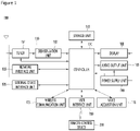
- FIG. 1 is a block diagram illustrating a configuration of a display device according to an embodiment of the present disclosure.
- a display device 100 includes a broadcast reception unit 130, an external device interface unit 135, a storage 140, a user input interface unit 150, a controller 170, a wireless communication unit 173, a voice acquisition unit 175, a display 180, an audio output unit 185, and a power supply unit 190.
- the broadcast reception unit 130 can include a tuner 131, a demodulation unit 132, and a network interface unit 133.
- the tuner 131 can select a specific broadcast channel according to a channel selection command.
- the tuner 131 may receive broadcast signals for the selected specific broadcast channel.
- the demodulation unit 132 can divide the received broadcast signals into video signals, audio signals, and broadcast program related data signals and restore the divided video signals, audio signals, and data signals to an output available form.
- the network interface unit 133 provides an interface for connecting the display device 100 to a wired/wireless network including internet network.
- the network interface unit 133 can transmit or receive data to or from another user or another electronic device through an accessed network or another network linked to the accessed network.
- some content data stored in the display apparatus 100 can be transmitted to a user or an electronic device, which is selected from other users or other electronic devices pre-registered in the display apparatus 100.
- the network interface unit 133 can access a predetermined webpage through an accessed network or another network linked to the accessed network. That is, it may transmit or receive data to or from a corresponding server by accessing a predetermined webpage through network.
- the network interface unit 133 can receive contents or data provided from a content provider or a network operator. That is, the network interface unit 133 can receive contents such as movies, advertisements, games, VODs, and broadcast signals, which are provided from a content provider or a network provider, through network and information relating thereto.
- the network interface unit 133 can receive firmware update information and update files provided from a network operator and transmit data to an internet or content provider or a network operator.
- the network interface unit 133 can also select and receive a desired application among applications open to the air, through network.
- the external device interface unit 135 can receive an application or an application list in an adjacent external device and deliver it to the controller 170 or the storage 140.
- the external device interface 135 can also provide a connection path between the display device 100 and an external device.
- the external device interface 135 can receive at least one of image and audio output from an external device that is wirelessly or wiredly connected to the display device 100 and deliver it to the controller.
- An external device connectable to the external device interface unit 130 may be one of a set-top box, a Blu-ray player, a DVD player, a game console, a sound bar, a smartphone, a PC, a USB Memory, and a home theater system but this is just exemplary.
- the storage 140 can store signal-processed image, voice, or data signals stored by a program in order for each signal processing and control in the controller 170.
- the storage 140 can perform a function for temporarily store image, voice, or data signals output from the external device interface unit 135 or the network interface unit 133 and can store information on a predetermined image through a channel memory function.
- the storage 140 can also store an application or an application list input from the external device interface unit 135 or the network interface unit 133.
- the display device 100 can play content files (for example, video files, still image files, music files, document files, application files, and so on) stored in the storage 140 and provide them to a user.
- content files for example, video files, still image files, music files, document files, application files, and so on
- the user input interface unit 150 can deliver signals input from a user to the controller 170 or deliver signals from the controller 170 to a user.
- the user input interface unit 150 can receive or process control signals such as power on/off, channel selection, and screen setting from the remote control device 200 or transmit control signals from the controller 170 to the remote control device 200 according to various communication methods such as Bluetooth, Ultra Wideband (WB), ZigBee, Radio Frequency (RF), and IR.
- WB Ultra Wideband
- RF Radio Frequency
- the user input interface unit 150 can deliver, to the controller 170, control signals input from local keys (not shown) such as a power key, a channel key, a volume key, and a setting key.
- local keys such as a power key, a channel key, a volume key, and a setting key.
- Image signals that are image-processed in the controller 170 can be input to the display 180 and displayed as an image corresponding to corresponding image signals. Additionally, image signals that are image-processed in the controller 170 can be input to an external output device through the external device interface unit 135.
- Voice signals processed in the controller 170 can be output to the audio output unit 185. Additionally, voice signals processed in the controller 170 can be input to an external output device through the external device interface unit 135.
- control module 170 can control overall operations in the display device 100.
- controller 170 can control the display device 100 by a user command or internal program input through the user input interface unit 150 and download a desired application or application list into the display device 100 in access to network.
- the control unit 170 may output channel information selected by a user together with processed image or voice signals through the display 180 or the audio output unit 185.
- the controller 170 can output image signals or voice signals of an external device such as a camera or a camcorder, which are input through the external device interface unit 135, through the display 180 or the audio output unit 185.
- an external device such as a camera or a camcorder
- the controller 170 can control the display 180 to display images and control broadcast images input through the tuner 131, external input images input through the external device interface unit 135, images input through the network interface unit, or images stored in the storage 140 to be displayed on the display 180.
- an image displayed on the display 180 can be a still image or video and also can be a 2D image or a 3D image.
- the controller 170 can play content stored in the display device 100, received broadcast content, and external input content input from the outside, and the content can be in various formats such as broadcast images, external input images, audio files, still images, accessed web screens, and document files.
- the wireless communication unit 173 can perform a wired or wireless communication with an external electronic device.
- the communication unit 173 may communicate with an external device through wired or wireless communication.
- the communication unit 173 can perform short-range communication with an external device.
- the wireless communication unit 173 can support short-range communication by using at least one of Bluetooth TM , Radio Frequency Identification (RFID), Infrared Data Association (IrDA), Ultra Wideband (UWB), ZigBee, Near Field Communication (NFC), Wireless-Fidelity (Wi-Fi), Wi-Fi Direct, and Wireless Universal Serial Bus (USB) technologies.
- RFID Radio Frequency Identification
- IrDA Infrared Data Association
- UWB Ultra Wideband
- ZigBee Near Field Communication
- NFC Near Field Communication
- Wi-Fi Wireless-Fidelity
- Wi-Fi Direct Wireless Universal Serial Bus
- USB Wireless Universal Serial Bus
- the communication unit 173 can support wireless communication between the display device 100 and a wireless communication system, between the display device 100 and another display device 100, or between networks including the display device 100 and another display device 100 (or an external server) through
- the other display device 100 can be a mobile terminal such as a wearable device (for example, a smart watch, a smart glass, and a head mounted display (HMD)) or a smartphone, which is capable of exchanging data (or inter-working) with the display device 100.
- the wireless communication unit 173 can detect (or recognize) a communicable wearable device around the display device 100. Furthermore, if the detected wearable device is a device authenticated to communicate with the display device 100, the controller 170 can transmit at least part of data processed in the display device 100 to the wearable device through the wireless communication unit 173. Accordingly, a user of the wearable device can use the data processed in the display device 100 through the wearable device.
- the display 180 can convert image signals, data signals, or OSD signals, which are processed in the controller 170, or images signals or data signals, which are received in the external device interface unit 135, into R, G, and B signals to generate driving signals.
- the display 180 may be a rollable display.
- the rollable display may be retracted into the housing 183 (see FIG. 7 ) and rolled onto a roller 184 (see FIG. 7 ), or extended out of a housing 183 (see FIG. 7 ) and unrolled from the roller 184 (see FIG. 7 ).
- the display apparatus 100 may include a rollable display, and an area in which content is displayed may be increased or decreased according to extension or retraction of the rollable display.
- the display 180 to be described below may refer to a rollable display.
- the display device 100 shown in FIG. 1 is just one embodiment of the present disclosure and thus, some of the components shown can be integrated, added, or omitted according to the specification of the actually implemented display device 100.
- each block is to describe an embodiment of the present disclosure and its specific operation or device does not limit the scope of the present disclosure.
- the display device 100 can receive images through the network interface unit 133 or the external device interface unit 135 and play them without including the tuner 131 and the demodulation unit 132.
- the display device 100 can be divided into an image processing device such as a set-top box for receiving broadcast signals or contents according to various network services and a content playback device for playing contents input from the image processing device.
- an image processing device such as a set-top box for receiving broadcast signals or contents according to various network services
- a content playback device for playing contents input from the image processing device.
- an operating method of a display device can be performed by one of the display device described with reference to FIG. 1 , an image processing device such as the separated set-top box, and a content playback device including the display 180 and the audio output unit 185.
- the audio output unit 185 receives the audio processed signal from the controller 170 and outputs the sound.
- a remote control device is described according to an embodiment of the present disclosure.
- FIG. 2 is a block diagram illustrating a remote control device according to an embodiment of the present disclosure
- FIG. 3 is a view illustrating an actual configuration of a remote control device according to an embodiment of the present disclosure.
- a remote control device 200 can include a fingerprint recognition unit 210, a wireless communication unit 220, a user input unit 230, a sensor unit 240, an output unit 250, a power supply unit 260, a storage unit 270, a controller 280, and a voice acquisition unit 290.
- the wireless communication unit 225 transmits/receives signals to/from an arbitrary any one of display devices according to the above-mentioned embodiments of the present disclosure.
- the remote control device 200 may include an RF module 221 for transmitting/receiving signals to/from the display device 100 according to the RF communication standards and an IR module 223 for transmitting/receiving signals to/from the display device 100 according to the IR communication standards. Additionally, the remote control device 200 may include a Bluetooth module 225 for transmitting/receiving signals to/from the display device 100 according to the Bluetooth communication standards. Additionally, the remote control device 200 may include an NFC module 227 for transmitting/receiving signals to/from the display device 100 according to the Near Field Communication (NFC) communication standards and a WLAN module 229 for transmitting/receiving signals to/from the display device 100 according to the Wireless LAN (WLAN) communication standards.
- NFC Near Field Communication
- WLAN Wireless LAN
- the remote control device 200 can transmit signals containing information on a movement of the remote control device 200 to the display device 100 through the wireless communication unit 220.
- the remote control device 200 can receive signals transmitted from the display device 100 through the RF module 221 and if necessary, can transmit a command on power on/off, channel change, and volume change to the display device 100 through the IR module 223.
- the user input unit 230 can be configured with a keypad button, a touch pad, or a touch screen. Thus, a user can manipulate the user input unit 230 to input a command relating to the display device 100 to the remote control device 200. If the user input unit 230 includes a hard key button, a user can input a command relating to the display device 100 to the remote control device 200 through the push operation of the hard key button. This will be described with reference to FIG. 3 .
- the remote control device 200 can include a plurality of buttons.
- the plurality of buttons may include a fingerprint recognition button 212, a power button 231, a home button 232, a live button 233, an external input button 234, a voice adjustment button 235, a voice recognition button 236, a channel change button 237, a check button 238, and a back button 239.
- the fingerprint recognition button 212 can be a button for recognizing a user's fingerprint. According to an embodiment of the present disclosure, the fingerprint recognition button 212 can perform a push operation and receive a push operation and a fingerprint recognition operation.
- the power button 231 can be a button for turning on/off the power of the display device 100.
- the power button 232 can be a button for moving to the home screen of the display device 100.
- the live button 233 can be a button for displaying live broadcast programs.
- the external input button 234 can be a button for receiving an external input connected to the display device 100.
- the voice adjustment button 235 can be a button for adjusting the size of a volume output from the display device 100.
- the voice recognition button 236 can be a button for receiving a user's voice and recognizing the received voice.
- the channel change button 237 can be a button for receiving broadcast signals of a specific broadcast channel.
- the check button 238 can be a button for selecting a specific function and the back button 239 can be a button for returning to a previous screen.
- FIG. 2 is described.
- the user input unit 230 includes a touch screen, a user can touch a soft key of the touch screen to input a command relating to the display device 100 to the remote control device 200. Additionally, the user input unit 230 can include various kinds of input mechanisms manipulated by a user, for example, a scroll key and a jog key, and this embodiment does not limit the scope of the present disclosure.
- the sensor unit 240 can include a gyro sensor 241 or an acceleration sensor 243 and the gyro sensor 241 can sense information on a movement of the remote control device 200.
- the gyro sensor 241 can sense information on an operation of the remote control device 200 based on x, y, and z axes and the acceleration sensor 243 can sense information on a movement speed of the remote control device 200.
- the remote control device 200 can further include a distance measurement sensor and sense a distance with respect to the display 180 of the display device 100.
- the output unit 250 can output image or voice signals corresponding to a manipulation of the user input unit 235 or corresponding to signals transmitted from the display device 100. A user can recognize whether the user input unit 235 is manipulated or the display device 100 is controlled through the output unit 250.
- the output unit 250 can include an LED module 251 for flashing, a vibration module 253 for generating vibration, a sound output module 255 for outputting sound, or a display module 257 for outputting an image, if the user input unit 235 is manipulated or signals are transmitted/received to/from the display device 100 through the wireless communication unit 225.
- the power supply unit 260 supplies power to the remote control device 200 and if the remote control device 200 does not move for a predetermined time, stops the power supply, so that power waste can be reduced.
- the power supply unit 260 can resume the power supply if a predetermined key provided at the remote control device 200 is manipulated.
- the storage unit 270 can store various kinds of programs and application data necessary for a control or operation of the remote control device 200. If the remote control device 200 transmits/receives signals wirelessly through the display device 100 and the RF module 221, the remote control device 200 and the display device 100 transmits/receives signals through a predetermined frequency band.
- the controller 280 of the remote control device 200 can store, in the storage unit 270, information on a frequency band for transmitting/receiving signals to/from the display device 100 paired with the remote control device 200 and refer to it.
- the controller 280 controls general matters relating to a control of the remote control device 200.
- the controller 280 can transmit a signal corresponding to a predetermined key manipulation of the user input unit 235 or a signal corresponding to a movement of the remote control device 200 sensed by the sensor unit 240 to the display device 100 through the wireless communication unit 225.
- the voice acquisition unit 290 of the remote control device 200 can obtain voice.
- the voice acquisition unit 290 can include at least one microphone 291 and obtain voice through the microphone 291.
- FIG. 4 is described.
- FIG. 4 is a view of utilizing a remote control device according to an embodiment of the present disclosure.
- FIG. 4(a) illustrates that a pointer 205 corresponding to the remote control device 200 is displayed on the display 180.
- a user can move or rotate the remote control device 200 vertically or horizontally.
- the pointer 205 displayed on the display 180 of the display device 100 corresponds to a movement of the remote control device 200. Since the corresponding pointer 205 is moved and displayed according to a movement on a 3D space as show in the drawing, the remote control device 200 can be referred to as a spatial remote controller.
- FIG. 4(b) illustrates that if a user moves the remote control device 200, the pointer 205 displayed on the display 180 of the display device 100 is moved to the left in correspondence thereto.
- Information on a movement of the remote control device 200 detected through a sensor of the remote control device 200 is transmitted to the display device 100.
- the display device 100 can calculate the coordinates of the pointer 205 from the information on the movement of the remote control device 200.
- the display device 100 can display the pointer 205 to match the calculated coordinates.
- FIG. 4(c) illustrates that while a specific button in the remote control device 200 is pressed, a user moves the remote control device 200 away from the display 180.
- a selection area in the display 180 corresponding to the pointer 205 can be zoomed in and displayed largely.
- a selection area in the display 180 corresponding to the pointer 205 can be zoomed out and displayed reduced.
- a selection area can be zoomed out and if the remote control device 200 is close to the display 180, a selection area can be zoomed in.
- the recognition of a vertical or horizontal movement can be excluded. That is, if the remote control device 200 is moved away from or close to the display 180, the up, down, left, or right movement cannot be recognized and only the back and forth movement can be recognized. While a specific button in the remote control device 200 is not pressed, only the pointer 205 is moved according to the up, down, left or right movement of the remote control device 200.
- the moving speed or moving direction of the pointer 205 can correspond to the moving speed or moving direction of the remote control device 200.
- a pointer in this specification means an object displayed on the display 180 in correspondence to an operation of the remote control device 200. Accordingly, besides an arrow form displayed as the pointer 205 in the drawing, various forms of objects are possible. For example, the above concept includes a point, a cursor, a prompt, and a thick outline. Then, the pointer 205 can be displayed in correspondence to one point of a horizontal axis and a vertical axis on the display 180 and also can be displayed in correspondence to a plurality of points such as a line and a surface.
- FIG. 5 is a cross-sectional view illustrating an internal part of a housing of a display device 100 according to the present disclosure.
- the display device 100 can include a housing 183, a display 180 drawn into or out from the housing 183, and a roller 184 that guides the display 180 to be wound or unwound.
- the roller 184 can be received in the housing 183.
- the roller 184 can be a rotatable guide bar.
- the roller 184 may be rotatable such that the display 180 is wound or unwound. For example, as shown in FIG. 5 , when the roller 184 rotates in the R1 direction, the display 180 can be drawn out from the housing 183. In contrast, when the roller 184 rotates in the R2 direction, the display 180 can be drawn into the housing 183, while being wound around the roller 184. Also, the display 180 may be extended or retracted in the left and right directions according to the arrangement of the housing.
- the display 180 can be drawn out from the housing 183 or can be drawn into the housing 183 according to rotation of the roller 184.
- the controller 170 can control the display 180 to display content in an area of the display 180 drawn out from the housing 183.
- the display device 100 can further include a cover 186.
- the cover 186 may be disposed in the housing 183 and protecting the display 180 drawn in the housing 183.
- the area where content is displayed can increase or decrease. That is, the display area of the content of the display 180 varies as the display 180 is drawn out or drawn in.
- FIG. 6 is a view illustrating an appearance of the display device when a mode of the display is the zero view mode according to an embodiment of the present disclosure
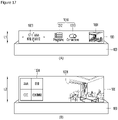
- FIG. 7 is a view illustrating an appearance of the display device when a mode of the display is the partial view mode according to an embodiment of the present disclosure
- FIG. 8 is a view illustrating an appearance of the display device when a mode of the display is the full view mode according to embodiments of the present disclosure.
- the zero view mode is a mode in which the display 180 operates in a state in which the display 180 is entirely drawn in the housing 183.
- the display device 100 can control the mode of the display to be in the zero view mode.
- the display 180 When the display 180 is in the zero view mode, the display 180 does not display content in the entire area of the display 180.
- the display 180 can also be turned off in the zero view mode.
- the partial view mode is a mode in which the display 180 operates in a state of being partially drawn out from the housing 183.
- the mode of the display can be controlled in the partial view mode.
- the display 180 can display content only in an area of the display 180 drawn out from the housing 183. That is, in the partial view mode, the content is not displayed in an area of the display 180 drawn in the housing 183.
- the full view mode is a mode in which the display 180 operates in a state of being maximally drawn out from the housing 183. That is, the full view mode is a mode in which a length of the display 180 drawn out from the housing 183 is a maximum.
- the display can be controlled in the full view mode, and here, the normal mode can be a mode in which a broadcast image, an input image from the external device interface unit 135, and the like is output.
- the display 180 When the display 180 is in the full view mode, content can be displayed in an area of the display 180 drawn from the housing 183. In the full view mode, the display 180 can display content in the entire area of the display 180 available for outputting an image.
- the display apparatus 100 may include a housing 183 and a display 180 extendable from and retractable into the housing 183, and may be installed in a such a way that the housing 183 is seated on the floor as shown in FIG. 7 .
- the display 180 may be elongated in an upward direction when the display unit 180 is extended from the housing 183.
- content may be displayed on the extended area of the display 180.
- the display 180 is additionally extended from the housing 183 as shown in FIG. 8 , content may be displayed on the entire extended areas.
- the extended length L of the display 180 may be variable.
- the display apparatus 100 may include a housing 183 and a display 180 extendable from and retractable into the housing 183, and may be installed in a such a way that the housing 183 is fixed to a wall or the like.
- the display 180 may be elongated in a left or right direction when the display unit 180 is extended from the housing 183.
- the display apparatus 100 is not limited to the examples described above, and may be installed in various forms.
- the display apparatus 100 may be installed in such a way that the housing 183 is fixed to the ceiling.
- the display area of the content may be changed according to the extended length L of the display 180.
- the display 180 when the power is turned off, the display 180 may be controlled in a zero-view mode, and when the power is turned on, the display 180 may be controlled in a partial-view mode or a full-view mode.
- the display 180 When the display 180 is fully retracted into the housing 183 and then starts to be extended from the housing 183 according to a power-on command, the content is displayed while a part is being cut until the display 180 is completely extended, so that a user may need to wait a predetermined time to view the entire content.
- an object of the present disclosure is to provide a display apparatus 100 for allowing a user to grasp the contents of content even when the display 180 is not extended fully.
- FIG. 9 is a flowchart showing a method of operating a display apparatus according to an embodiment of the present disclosure.
- the control unit 170 may receive a command to extend the display 180 (S10).
- the command to extend the display 180 may be a command to extend the display 180 from the housing 183 or to increase the length of the display 180 extended from the housing 183.
- control unit 170 may recognize, as the command to extend the display 180, a command that requires additional extension of the display 180, such as a power-on command, a command to enter the partial-view mode from the zero-view mode, and a command to enter the full-view mode from the partial-view mode.
- control unit 170 When the control unit 170 receives the command to extend the display 180, the control unit 170 may display the entire content 1001 (see FIG. 10 ) on the extended display 180 while the display 180 is being extended (S20).
- the content 1001 may mean an image displayable on a screen through the display 180.
- the content 1001 may be a broadcast image received by the control unit 170 through the broadcast receiving unit 130, an external device image received by the control unit 170 through the external device interface unit 135, or an image stored in the storage unit 140. This is only an example, and the content 1001 may mean any content that can be displayed on the display 180, such as pictures, photos, images, and applications.
- the control unit 170 may reduce the size of the content 1001 such that the entire content 1001 is displayed on the extended display 180 while the display 180 is being extended.
- control unit 170 may control the display 180 such that the image size of the content 1001 increases while the image ratio of the content 1001 is being maintained when the display 180 is being extended.
- the image ratio being maintained may mean that the horizontal-vertical ratio of the image is kept constant, and the image size increasing may mean that the size of the image also increases as the area of the extended display 180 increases.
- the size of the image may increase in proportion to the extent to which the display 180 is extended, but it does not mean only that the image size increases proportionally.
- FIG. 10 is an exemplary diagram showing an example of a method of displaying entire content in a display apparatus according to an embodiment of the present disclosure.
- the control unit 170 may control the display 180 such that the entire content 1001 is displayed in a reduced size.
- the control unit 170 may control the display 180 such that the image size of the content 1001 is increasing gradually while the image ratio of the content 1001 is maintained when the display 180 is being extended by L2.
- the image ratio of the displayed content 1001 in a state in which the display 180 is extended by L1 may be identical to the image ratio of the displayed content 1001 in a state in which the display 180 is extended by L2, and the image size of the content 1001 displayed in a state in which the display 180 is extended by L1 may be smaller than the image size of the content 1001 displayed in a state in which the display 180 is extended by L2.
- control unit 170 may control the display 180 such that the image ratio of the content 1001 is maintained and the image size of the content 1001 is displayed as in (B) of FIG. 10 while the display 180 is being extended by L3.
- control unit 170 may further display a menu 1010 (see FIG. 22 ) in a remaining area, which will be described with reference to FIG. 22 .
- control unit 170 may adjust the size of the content 1001 such that the entire content 1001 is displayed on the display 180 regardless of the image ratio of the content 1001 and display the content 1001 on the display 180.
- the method of displaying the content 1001 is not limited to the example shown in FIG. 10 .
- FIG. 11 is another exemplary diagram showing an example of a method of displaying entire content in a display apparatus according to an embodiment of the present disclosure.
- control unit 170 may increase the size of the content 1001 based on the extended length of the display 180 when increasing the size of the content 1001.
- the control unit 170 may control the display 180 to display the content 1001 such that the image size of the content 1001 increases to the maximum size according to the extended length of the display 180 while the image ratio of the content 1001 is maintained when the extended length of the display 180 increases from L1 to L2.
- the control unit 170 may control the display 180 to display the content 1001 such that the image size of the content 1001 increases to the maximum size according to L3 while the extended length of the display 180 increases by L3.
- an image of the maximum size that can be displayed through the display 180 may be provided while the image ratio is maintained when the display 180 is being extended.
- the display apparatus 100 may change a method or scheme of displaying the content 1001 according to the extended length of the display 180.
- FIG. 12 is an exemplary view illustrating a method for displaying content in a display apparatus according to an embodiment of the present disclosure.
- control unit 170 may control the display 180 such that the content 1001 is displayed in the form of a list.
- the control unit 170 may convert the content 1001 into text information, and control the display 180 to display text information in the form of a list.
- the control unit 170 may convert the content 1001 into text information by itself and display text information in the form of a list, or may receive text information and display the text information in the form of a list.
- items may be added to the list. For example, two items of the list displayed as the content 1001 may be displayed as shown in (A) of FIG. 12 , and then the number of items in the list may increase to three or more according to the extension of the display 180.
- control unit 170 may control the display 180 to display the content 1001 in the form of a thumbnail.
- control unit 170 may control the display 180 to display the content 1001 in the form of a thumbnail.
- control unit 170 may control the display 180 to display the content 1001 in a full screen form.
- control unit 170 may control the display 180 to display the content 1001 provided by an application in a full screen form.
- the full screen form may mean a basic display form of the content 1001.
- control unit 170 may control the display 180 to preferentially display user preference information.
- control unit 170 may control the display 180 to display the user preference information first and further display posterior information according to the extension of the display 180.
- control unit 170 may control the size and image ratio of the content 1001 such that the entire content 1001 is displayed until the display 180 is extended to a target length according to a command to extend the display 180.
- the target length may vary depending on the type of the command to extend the display 180.
- the display apparatus 100 may further display a menu 1010 on the extended display 180 while the display 180 is being extended. That is, the display apparatus 100 may display the content 1001 and the menu 1010 together while the display 180 is being extended.
- the menu 1010 may mean an icon or a collection of icons for receiving a control command of the display apparatus 100.
- the menu 1010 may include icons for allowing a user to select information to be displayed on the display 180 such as an application icon 1011, a program icon 1012, and an external device icon 1013.
- the menu 1010 may include an application providing information such as a clock application or a weather application.
- FIG. 13 is a flowchart illustrating a method for displaying content and a menu together in a display apparatus according to an embodiment of the present disclosure.
- the control unit 170 may receive a command to extend the display 180 (S10).
- control unit 170 When the control unit 170 receives the command to extend the display 180, the control unit 170 may display the entire content 1001 on the extended display 180 while the display 180 is being extended (S20).
- Steps S10 and S20 are the same as those described with reference to FIG. 9 , and thus redundant descriptions will be omitted.
- the control unit 100 may further display a menu 1010 on the extended display 180 while the display 180 is being extended (S22).
- the control unit 170 may control the display 180 such that the menu 1010 is displayed in an area other than the content 1001, or the menu 1010 is displayed in an overlapping manner on the content 1001.
- FIG. 14 is an exemplary view illustrating a method for further displaying a menu in a display apparatus according to an embodiment of the present disclosure.
- the control unit 170 may control the display 180 such that the menu 1010 is displayed together with the content 1001 of a first size when the display 180 is extended by L1 as shown in FIG. 14(A) , control the display 180 such that the menu 1010 is displayed together with the content 1001 of a second size when the display 180 is extended by L2 as shown in FIG. 14(B) , and control the display 180 such that the menu 1010 is displayed together with the content 1001 of a third size when the display 180 is extended by L3 as shown in FIG. 14(C) .
- the first size may be smaller than the second size, and the second size may be smaller than the third size.
- the vertical length of the first size may be equal to L1 which is the extended length of the display 180, or smaller than L1 by a predetermined size
- the vertical length of the second size may be equal to L2 which is the extended length of the display 180, or smaller than L2 by a predetermined size
- the vertical length of the third size is equal to L3 which is the extended length of the display 180, or smaller than L3 by a predetermined size.
- the control unit 170 may display the menu 1010 in an area other than the content 1001 of the first size in the extended display 180.
- the control unit 170 may display the menu 1010 in an area other than the content 1001 of the second size in the extended display 180.
- the control unit 170 may display the menu 1010 in an area other than the content 1001 of the third size in the extended display 180. Accordingly, the control unit 170 may control the display 180 such that the menu 1010 is displayed while a display position or arrangement method of the menu 1010, the number or size of the icons, or the like is being changed as the size of the content 1001 changes.
- control unit 170 may control display 180 such that the display form of the menu 1010 is changed in an area other than the content 1001 while increasing the size of the content 1001 according to the extended length of the display 180, when the display 180 is being extended.
- control unit 170 may receive an input signal for selecting any one icon in the menu 1010 (S24).
- Any one icon in the menu 1010 means one of the icons for which the user selects information to be displayed through the display 180, such as the application icon 1011, the program icon 1012, and the external device icon 1013.
- control unit 170 When the control unit 170 receives an input signal for selecting any one icon in the menu 1010 (S24), the control unit 170 may control the display 180 such that the display 180 switches to and displays a sub-menu 1020 corresponding to a received icon selection signal or the content 1001 corresponding to the received icon selection signal.
- an input signal for selecting any one icon in a menu is referred to as an icon selection signal.
- the icon selection signal may be an input signal for controlling the sub-menu 1020 to be displayed according to the type of a selected icon, or an input signal for controlling the content 1001 being displayed to be changed.
- a method of operating the display apparatus 100 when the icon selection signal is an input signal for controlling the sub-menu 1020 to be displayed will be descri bed.
- the sub-menu 1020 may mean a collection of icons for receiving an additional input signal when the additional input signal is required to control the display apparatus 100 as a result of receiving the icon selection signal.
- the sub-menu 1020 of the application icon 1011 is a collection of application icons that can be currently executed on the display apparatus 100 among applications, such as a video sharing application icon 1021 and a TV replay application icon 1022 and the like.
- the sub-menu 1020 of the program icon 1012 may mean a collection of icons that provide program information and additional channel information, such as a channel information icon 1023 or a channel list icon 1024.
- the sub-menu 1020 of the external device icon 1013 may mean a collection of external device icons connected to the display apparatus 100, such as an HDMI icon 1025, a smartphone icon 1026, and the like.
- sub-menus 1020 are merely exemplary, and there are various sub-menus according to the types of icons.
- the control unit 170 may control the display 180 to display the sub-menu 1020 instead of the currently displayed menu 1010 (S26). Also, the control unit 170 may control the display 180 to display the sub-menu 1020 of the selected icon while displaying the currently displayed menu 1010 as it is.
- FIGS. 15 and 16 are exemplary views illustrating a method of operating a display apparatus when the display apparatus receives an input signal for selecting a sub-menu according to an embodiment of the present disclosure.
- control unit 170 When the control unit 170 receives an input signal for selecting the application icon 1011 as shown in (A) of FIG. 15 , the control unit 170 may determine whether there is a sub-menu 1020 of the application icon 1011. When there is the sub-menu 1020 of the application icon 1011, the control unit 170 may control the display 180 to display a video sharing application icon 1021 and a TV replay application icon 1022, which are the sub-menus 1020 of the application icon 1011 as shown in (B) of FIG. 15 . In this case, the control unit 170 may display the program icon 1012 and the external device icon 1013 among the menu 1010 being displayed as they are.
- the video sharing application icon 1021 and the TV replay application icon 1022, which are sub-menus 1020 of the application icon 1011, are merely examples, and sub-menus 1020 of the application icon 1011 may be changed according to the type of application that can be executed on the display apparatus 100.
- control unit 170 may determine whether there is a sub-menu 1020 of the program icon 1011. When there is the sub-menu 1020 of the program icon 1012, the control unit 170 may control the display 180 to display the channel list icon 1024, which is the sub-menu 1020 of the program icon 1012, as shown in (B) of FIG. 16 .
- control unit 170 may control display 180 such that the remaining unselected icons are displayed as they are, as in the example of FIG. 15 , or the remaining unselected icons are not displayed as in the example of FIG. 16 .
- the method of displaying the sub-menu 1020 in the display apparatus 100 may be different for each icon.
- the method of displaying the sub-menu 1020 in the display apparatus 100 according to an embodiment of the present disclosure may be different depending on the extended length of the display 180.
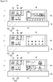
- FIG. 17 is an exemplary diagram showing a method of displaying a sub-menu in different manners according to the extended length of the display.
- the sub-menu 1020 of the program icon 1012 may be a channel information icon 1023. That is, when the control unit 170 receives a command to select the program icon 1012 while the extended length of the display 180 is less than or equal to a preset length, the control unit 170 may display the channel information icon 1023 as the sub-menu 1020 of the program icon 1012.
- the channel information icon 1023 may mean display of information related to a program, such as channel information, broadcaster information, a broadcast program name, and a broadcast time of the content 1001 being displayed on the display 180.
- the sub-menu 1020 of the program icon 1012 may be a channel list icon 1024.
- the control unit 170 may display the channel list icon 1023 as the sub-menu 1020 of the program icon 1012.
- the channel list icon 1024 may mean display of a list of currently aired programs and other channels in the form of thumbnails.
- the method of displaying the sub-menu 1020 in the display apparatus 100 may be different according to the extended length of the display 180. That is, the display apparatus 100 may display the sub-menu 1020 including more information as the extended length is longer.
- the icon selection signal is an input signal for changing the content 1001.
- the control unit 170 may control the display 180 to switch into and display the content 1001 corresponding to the received icon selection signal.
- the input signal for switching the content 1010 may mean an input signal for switching and displaying the content 1001 being currently displayed through the display 180.
- the control unit 170 may recognize the input signal as a channel change signal for the content 1001 being currently displayed through the display 180. That is, the control unit 170 may control the display 180 to switch into and display the content 1001 of a selected channel, instead of the content 1001 being currently displayed.
- the control unit 170 may recognize the input signal as an input signal for switching the content 1001 being currently displayed through the display 180 into content 1001 corresponding to the video sharing application. That is, the control unit 170 may control the display 180 to switch into and display the content 1001 corresponding to the selected video sharing application, instead of the content 1001 being currently displayed.
- FIG. 18 is an exemplary diagram illustrating a method of operating a display apparatus when an input signal for switching content is a channel switch signal.
- the control unit 170 may recognize the input signal as a channel change signal for the content 1001 being currently displayed through the display 180. That is, as shown in (B) of FIG. 18 , the control unit 170 may control display 180 to switch into and display the content 1001 of channel "BBB", which is the selected channel, instead of the content 1001 of FIG. 18 (A) that was being displayed.
- the control unit 170 may change the content 1001 according to an input signal for up, down, left, and right keys of the remote control device 200.
- FIG. 19 is an exemplary diagram illustrating a method of operating a display apparatus when an input signal for switching content is a signal for switching into an external device image.
- the external device image is an image input from an external device as shown in (A) of FIG. 19 , a mirroring image of an external device as shown in (B) of FIG. 19 , or a thumbnail indicating a file stored in an external device as shown in (C) of FIG. 19 .
- the control unit 170 may recognize the input signal as an input signal for switching the content 1001 being currently displayed through the display 180 to the content 1001 corresponding to the image of the external device connected to HDMI, and control the display 180 to switch into and display the content 1001 of the external device connected to HDMI, instead of the content 1001 being currently displayed.
- the control unit 170 may recognize the input signal as an input signal for switching the content 1001 being currently displayed through the display 180 to content 1001 corresponding to the image of the smartphone connected to the display apparatus 100, and control the display 180 to switch into and display the content 1001 which is the mirroring image of the smartphone connected to the display apparatus 100, instead of the content 1001 being currently displayed.
- the control unit 170 may recognize the input signal as an input signal for switching the content 1001 being currently displayed through the display 180 to the content 1001 corresponding to the image of the external device connected to a USB port, and control the display 180 to switch into and display the content 1001 of the external device connected to the USB port, instead of the content 1001 being currently displayed.
- the display apparatus 100 may switch and display the content 1001 in response to the icon selection signal while the display 180 is being extended.
- control unit 170 may control the display 180 to stop extension of the display 180 (S40).
- the extension stop command for the display 180 may include an icon selection signal, an extension stop command by a user, a stop command according to the maximum extension of the display 180, and the like.
- control unit 170 may recognize the icon selection signal as the extension stop command for the display 180.
- control unit 170 may control a roller 184 to stop extension of the display 180 immediately or to stop extension of the display 180 after the display 180 is extended to a preset length.
- the preset length may mean a length that is 80% of the maximum length of the display 180, but this is only given as an example for convenience of description.
- control unit 170 may control the display 180 to display a screen indicating extension stop of the display 180.
- FIG. 20 is an exemplary diagram illustrating a method of receiving a maximum extension command when the extension of the display apparatus is stopped before being extended to a maximum length according to an embodiment of the present disclosure.
- control unit 170 may control the display 180 to display a screen indicating extension stop as shown in (A) of FIG. 20 .
- the screen indicating extension stop may be a screen indicating that extension is stopped before reaching the maximum extension length of the display 180.
- the screen indicating extension stop may include a full screen icon 1014.
- the full screen icon 1014 may mean an icon for receiving a command to display only the currently displayed content 1001 excluding the menu 1010 on the display 180.
- the full screen icon 1014 may mean an icon for selecting whether to extend the display 180 to the maximum length while displaying only the currently displayed content 1001 on the display 180.
- control unit 170 may recognize it as receiving the maximum extension command for the display 180.
- control unit 170 may recognize that the maximum extension command is received even when no user input is detected for more than a predetermined time in a state in which extension is stopped at a preset length before the display 180 reaches the maximum extension length. For example, when the extension is stopped because the extended length of the display 180 reaches 80% of the maximum extension length, the control unit 170 may control the roller 184 such that the display 180 is extended to the maximum extension length if no user input is detected for more than the predetermined time.
- the control unit 170 may extend the display 180 to the maximum extension length as shown in (B) FIG. 20 and control the display 180 to display only the content 1001 on the display 180.
- L2 may be a length corresponding to 80% of the maximum extension length
- L4 may be the maximum extension length of the display 180.
- the position or arrangement of icons in the menus displayed on the display 180 may be changed.
- a user tries to select an icon, it may be difficult for the user to select a desired icon due to a change in the position or arrangement of the icons.
- control unit 170 may control the display 180 to allow the position of the pointer 205 to be fixed on the icon while the display 180 is extended or display an icon on which the pointer 205 is located to be fixed.
- FIG. 21 is an exemplary diagram illustrating a method of displaying an icon and a pointer positioned on the icon in a display apparatus according to an embodiment of the present disclosure.
- the control unit 170 may control the display 180 to change of the position of the pointer 205 and display the pointer 205. That is, the control unit 170 may recognize an icon being displayed in an area where the pointer 205 is located, and control the display 180 such that the pointer 205 is located on the recognized icon even when the position of the recognized icon is changed.
- control unit 170 may control the display 180 such that the pointer 205 is located and displayed on the external device icon 1013 even when the position and arrangement of the icons are changed as shown in (B) of FIG. 21 .
- control unit 170 may control the display 180 to fix the position of the displayed pointer 205 and display the pointer 205.
- control unit 170 may control the display 180 such that the position of the icon is fixed and the icon is displayed according to the extension of the display 180.
- FIG. 22 is an exemplary diagram illustrating a method of displaying an icon and a pointer positioned on the icon in a display apparatus according to an embodiment of the present disclosure.
- control unit 170 may control the display 180 to display the icon at a fixed position as shown in (B) of FIG. 22 .
- the position or size of the content 1001 may be adjusted according to the fixed icon position.
- the display apparatus 100 capable of allowing a user to easily perform selection when the user tries to select an icon displayed on the display 180 while the display 180 is being extended.
- the display apparatus 100 capable of allowing the user to grasp the contents of the content 1001 even when only a part of the content 1001 is displayed while the display 180 is being extended.
- the display apparatus 100 may control a manner for displaying the content 1001 so as to allow the user to grasp the contents of the content 1001 even when only a part of the content 1001 is displayed while the display 180 is being extended.
- control unit 170 may display a main part of the content 1001 first while the display 180 is being extended.
- the main part of the content 1001 may mean a partial part of the content 1001 that enables the user to immediately grasp the contents of the content 1001 even when the entire content 1001 is not displayed.
- the main part of the content 1001 may be different depending on the type of the content 1001. For example, when the content 1001 is a news image, a main part may be a subtitle, and when the content 1001 is a drama, the main part may be an actor/actress's face.
- the control unit 170 may determine a main part of the content 1001 being displayed, and control the display 180 such that the main part is displayed first in an extended portion of the display 180.
- FIG. 23 is an exemplary diagram illustrating a method of controlling a display form of content in a display apparatus according to an embodiment of the present disclosure.
- the control unit 170 may determine the subtitle of the content 1001 as a main part.
- the control unit 170 may control the display 180 to sequentially display the subtitles of the content 1001 in the extended area.
- the control unit 170 may control the display 180 to additionally display parts other than the subtitles of the content 1001 according to the additionally-extended length of the display 180.
- the control unit 170 may control the display 180 to display the entire content 1001.
- the display apparatus 100 capable of allowing a user to grasp the contents of the content 1001 even when the display 180 is not fully extended.
Abstract
Description
- The present disclosure relates to a display device, and more particularly, to a display device having a flexible display.
- A display device has a function of receiving, processing, and displaying an image to be viewed by a user. For example, the display device receives a broadcast signal selected by a user among broadcast signals transmitted from a broadcasting station, separates an image signal from the received signal, and re-displays the separated image signal on a display.
- Recently, by virtue of development of broadcasting technology and network technology, a function of a display device has been significantly diversified and accordingly the performance of the device has also been enhanced. That is, the display device has developed to provide various different contents as well as simply broadcast content to a user. For example, the display device can provide gameplay, listening to music, Internet shopping, user customized information, or the like using various applications as well as programs received from a broadcasting station. In order to perform such extended functions, the display device is basically connected to other devices or networks using various communication programs and provides a ubiquitous computing environment to a user. That is, the display device has evolved to a smart device for achieving connectivity to a network and ubiquitous computing.
- On the other hand, in recent years, a flexible display that has enough elasticity to be greatly deformed has been developed. Such a flexible display is deformable enough to be rolled into a main body of the display apparatus.
- The display apparatus may include a flexible display as described above in which an area protruding to the outside of the display is changed by being rolled or unrolled in a direction guided by a roller. By using such a rollable display, the display apparatus may have a more compact structure.
- Accordingly, the entire display area may be exposed to the outside to display the content or only a part of the display area may be exposed to display the content in only a partial area.
- On the other hand, it takes a certain time until the entire display area is exposed, and since only a part of the content is displayed in a state where only a part of the display area is exposed, there is a problem in that a viewer cannot accurately grasp the contents of the content.
- An object of the present disclosure is to provide a display apparatus capable of allowing a user to view the entire content even when the display is being extended.
- An object of the present disclosure is to provide a display apparatus capable of utilizing a remaining area other than the content when the display is being extended.
- An object of the present disclosure is to provide a display apparatus capable of minimizing interference with a user's image viewing when the display is being extended.
- The display apparatus according to the embodiment of the present disclosure may comprise a housing, a display, a roller accommodated in the housing to rotate to roll or unroll the display and a control unit configured to control the display such that the entire content is displayed on the display extended from the housing while the display is being extended from the housing.
- The control unit is configured to control the display such that the entire content is displayed while an image ratio of the content is being maintained.
- The control unit is configured to control the display such that the entire content is displayed while an image size of the content increases when the display is being extended from the housing.
- The display is configured to display the entire content such that an image size of the content increases while the image ratio of the content is maintained when the display is being extended from the housing.
- The control unit is configured to maintain the image ratio of the content, and adjust the image size of the content to a maximum size according to the extended length of the display.
- The control unit is configured to control the display such that a menu is further displayed on the display extended from the housing.
- The control unit is configured to control the display such that the menu is displayed in an area other than the content in an extended area of the display which is extended from the housing.
- The control unit is configured to control the display to switch content in response to an input signal instead of the content or display a sub-menu corresponding to the input signal instead of the menu when receiving the input signal for selecting any one icon in the menu.
- The control unit is configured to control the display to display an image corresponding to a selection command for selecting a specific external device icon, instead of the content when the selection command is received.
- The content is a broadcast image, and wherein the menu includes at least one of an application icon, a program icon, and an external device icon.
- The control unit is configured to control the roller to stop the extension of the display when an input signal for selecting any one of the menu is received while the display is being extended from the housing.
- The control unit is configured to control the roller such that the display is extended to a preset length when an input signal for selecting any one of the menu is received while the display is being extended from the housing is received.
- The control unit is configured to control the display to display a screen indicating stop of extension of the display when the extension of the display is stopped before the display is extended to a maximum length.
- The screen indicating the stop of extension of the display further includes an icon for selecting whether to extend the display to the maximum length, wherein the control unit is configured to control the roller such that the display is extended to the maximum length when the selection command for the icon is received.
- The control unit is configured to control the display such that the content is displayed in a list form when the extended length of the display is less than or equal to a preset first length in a case where the content is displayed while the display is being extended from the housing.
- The control unit is configured to control the display such that the content is displayed in a thumbnail form when the extended length of the display is greater than the first length and less than or equal to a second length longer than the first length in a case where the content is displayed while the display is being extended from the housing.
- The control unit is configured to control the display such that the content is displayed in a full screen form when the extended length of the display is greater than the second length and less than or equal to a third length longer than the second length in a case where the content is displayed while the display is being extended from the housing.
- The control unit is configured to control the display to display user preference information preferentially when displaying the content in a list form or a thumbnail form.
- The control unit is configured to fix a position of a pointer is fixed on an icon when the pointer is located on any one icon in a case where an extended length of the display is increasing.
- The control unit is configured to fix a position of a pointer displayed on the display when the display is extended from the housing.
- According to an embodiment of the present disclosure, there is an advantage in that it is possible to provide a display apparatus capable of allowing a user to grasp the contents of content even when the display is not fully extended. That is, there is an advantage in that it is possible to provide a display apparatus for allowing a viewer to grasp the entire contents of the content even while the display is being extended.
- According to an embodiment of the present disclosure, there is an advantage in that it is possible to provide a display apparatus capable of utilizing an area where no content is displayed while the display is being extended, and thus executing various functions as well as displaying content when the display is being extended.
- According to an embodiment of the present disclosure, there is an advantage in that it is possible to provide a display apparatus capable of allowing the viewer to focus on the content by minimizing interference with a user's image viewing when the display is being extended.
-
-
FIG. 1 is a block diagram illustrating a configuration of a display device according to an embodiment of the present disclosure. -
FIG. 2 is a block diagram illustrating a remote control device according to an embodiment of the present disclosure. -
FIG. 3 is a view illustrating an actual configuration of a remote control device according to an embodiment of the present disclosure. -
FIG. 4 is a view of utilizing a remote control device according to an embodiment of the present disclosure. -
FIG. 5 is a cross-sectional view illustrating an internal part of a housing of adisplay device 100 according to the present disclosure. -
FIG. 6 is a view illustrating an appearance of the display device when a mode of the display is the zero view mode according to an embodiment of the present disclosure. -
FIG. 7 is a view illustrating an appearance of the display device when a mode of the display is the partial view mode according to an embodiment of the present disclosure. -
FIG. 8 is a view illustrating an appearance of the display device when a mode of the display is the full view mode according to embodiments of the present disclosure. -
FIG. 9 is a flowchart showing a method of operating a display apparatus according to an embodiment of the present disclosure. -
FIG. 10 is an exemplary diagram showing an example of a method of displaying entire content in a display apparatus according to an embodiment of the present disclosure. -
FIG. 11 is another exemplary diagram showing an example of a method of displaying entire content in a display apparatus according to an embodiment of the present disclosure. -
FIG. 12 is an exemplary view illustrating a method for displaying content in a display apparatus according to an embodiment of the present disclosure. -
FIG. 13 is a flowchart illustrating a method for displaying content and a menu together in a display apparatus according to an embodiment of the present disclosure. -
FIG. 14 is an exemplary view illustrating a method for further displaying a menu in a display apparatus according to an embodiment of the present disclosure. -
FIGS. 15 and16 are exemplary views illustrating a method of operating a display apparatus when the display apparatus receives an input signal for selecting a sub-menu according to an embodiment of the present disclosure. -
FIG. 17 is an exemplary diagram showing a method of displaying a sub-menu in different manners according to the extended length of the display. -
FIG. 18 is an exemplary diagram illustrating a method of operating a display apparatus when an input signal for switching content is a channel switch signal. -
FIG. 19 is an exemplary diagram illustrating a method of operating a display apparatus when an input signal for switching content is a signal for switching into an external device image. -
FIG. 20 is an exemplary diagram illustrating a method of receiving a maximum extension command when the extension of the display apparatus is stopped before being extended to a maximum length according to an embodiment of the present disclosure. -
FIG. 21 is an exemplary diagram illustrating a method of displaying an icon and a pointer positioned on the icon in a display apparatus according to an embodiment of the present disclosure. -
FIG. 22 is an exemplary diagram illustrating a method of displaying an icon and a pointer positioned on the icon in a display apparatus according to an embodiment of the present disclosure. -
FIG. 23 is an exemplary diagram illustrating a method of controlling a display form of content in a display apparatus according to an embodiment of the present disclosure. - Hereinafter, embodiments relating to the present disclosure will be described in detail with reference to the accompanying drawings. The suffixes "module" and "unit" for components used in the description below are assigned or mixed in consideration of easiness in writing the specification and do not have distinctive meanings or roles by themselves. In addition, in describing the embodiments disclosed herein, when it is determined that the detailed description of the related known technology may obscure the gist of the embodiments disclosed herein, the detailed description thereof will be omitted. The accompanying drawings are used to help easily understand various technical features and it should be understood that the embodiments presented herein are not limited by the accompanying drawings. As such, the present disclosure should be construed to extend to any alterations, equivalents and substitutes in addition to those which are particularly set out in the accompanying drawings.
- It will be understood that although the terms first, second, etc. can be used herein to describe various elements, these elements should not be limited by these terms. These terms are generally only used to distinguish one element from another.
- When an element is referred to as being "connected with" another element, the element can be connected with the other element or intervening elements can also be present. In contrast, when an element is referred to as being "directly connected with" another element, there are no intervening elements present.
- A singular representation can include a plural representation unless it represents a definitely different meaning from the context.
- It will be further understood that the terms "comprises," "comprising," "having," "having," "includes," "including" and/or variations thereof, when used in this specification, specify the presence of stated features, integers, steps, operations, elements, and/or components, but do not preclude the presence or addition of one or more other features, integers, steps, operations, elements, components, and/or groups thereof.
- The display device described in this specification refers to a TV, a smart TV, a network TV, a hybrid broadcast broadband television (HBBTV), an Internet TV, a web TV, an Internet protocol television (IPTV), digital signage, a desktop computer, a smartphone, a laptop computer, a digital broadcast terminal, a personal digital assistant (PDA), a portable multimedia player (PMP), a navigation system, a slate PC, a tablet PC, an ultrabook, a wearable device, etc. Including a rollable display. Here, rollable display means that a display can be rolled in the form of a roll and can include a flexible display, a foldable display, etc.
-
FIG. 1 is a block diagram illustrating a configuration of a display device according to an embodiment of the present disclosure. - Referring to
FIG. 1 , adisplay device 100 includes abroadcast reception unit 130, an externaldevice interface unit 135, astorage 140, a userinput interface unit 150, acontroller 170, awireless communication unit 173, avoice acquisition unit 175, adisplay 180, anaudio output unit 185, and apower supply unit 190. - The
broadcast reception unit 130 can include atuner 131, ademodulation unit 132, and anetwork interface unit 133. - The
tuner 131 can select a specific broadcast channel according to a channel selection command. Thetuner 131 may receive broadcast signals for the selected specific broadcast channel. - The
demodulation unit 132 can divide the received broadcast signals into video signals, audio signals, and broadcast program related data signals and restore the divided video signals, audio signals, and data signals to an output available form. - The
network interface unit 133 provides an interface for connecting thedisplay device 100 to a wired/wireless network including internet network. Thenetwork interface unit 133 can transmit or receive data to or from another user or another electronic device through an accessed network or another network linked to the accessed network. - Additionally, some content data stored in the
display apparatus 100 can be transmitted to a user or an electronic device, which is selected from other users or other electronic devices pre-registered in thedisplay apparatus 100. - The
network interface unit 133 can access a predetermined webpage through an accessed network or another network linked to the accessed network. That is, it may transmit or receive data to or from a corresponding server by accessing a predetermined webpage through network. - Then, the
network interface unit 133 can receive contents or data provided from a content provider or a network operator. That is, thenetwork interface unit 133 can receive contents such as movies, advertisements, games, VODs, and broadcast signals, which are provided from a content provider or a network provider, through network and information relating thereto. - Additionally, the
network interface unit 133 can receive firmware update information and update files provided from a network operator and transmit data to an internet or content provider or a network operator. - The
network interface unit 133 can also select and receive a desired application among applications open to the air, through network. - The external
device interface unit 135 can receive an application or an application list in an adjacent external device and deliver it to thecontroller 170 or thestorage 140. - The
external device interface 135 can also provide a connection path between thedisplay device 100 and an external device. Theexternal device interface 135 can receive at least one of image and audio output from an external device that is wirelessly or wiredly connected to thedisplay device 100 and deliver it to the controller. An external device connectable to the externaldevice interface unit 130 may be one of a set-top box, a Blu-ray player, a DVD player, a game console, a sound bar, a smartphone, a PC, a USB Memory, and a home theater system but this is just exemplary. - The
storage 140 can store signal-processed image, voice, or data signals stored by a program in order for each signal processing and control in thecontroller 170. - Additionally, the
storage 140 can perform a function for temporarily store image, voice, or data signals output from the externaldevice interface unit 135 or thenetwork interface unit 133 and can store information on a predetermined image through a channel memory function. - The
storage 140 can also store an application or an application list input from the externaldevice interface unit 135 or thenetwork interface unit 133. - The
display device 100 can play content files (for example, video files, still image files, music files, document files, application files, and so on) stored in thestorage 140 and provide them to a user. - The user
input interface unit 150 can deliver signals input from a user to thecontroller 170 or deliver signals from thecontroller 170 to a user. For example, the userinput interface unit 150 can receive or process control signals such as power on/off, channel selection, and screen setting from theremote control device 200 or transmit control signals from thecontroller 170 to theremote control device 200 according to various communication methods such as Bluetooth, Ultra Wideband (WB), ZigBee, Radio Frequency (RF), and IR. - Additionally, the user
input interface unit 150 can deliver, to thecontroller 170, control signals input from local keys (not shown) such as a power key, a channel key, a volume key, and a setting key. - Image signals that are image-processed in the
controller 170 can be input to thedisplay 180 and displayed as an image corresponding to corresponding image signals. Additionally, image signals that are image-processed in thecontroller 170 can be input to an external output device through the externaldevice interface unit 135. - Voice signals processed in the
controller 170 can be output to theaudio output unit 185. Additionally, voice signals processed in thecontroller 170 can be input to an external output device through the externaldevice interface unit 135. - Besides that, the
control module 170 can control overall operations in thedisplay device 100. - Additionally, the
controller 170 can control thedisplay device 100 by a user command or internal program input through the userinput interface unit 150 and download a desired application or application list into thedisplay device 100 in access to network. - The
control unit 170 may output channel information selected by a user together with processed image or voice signals through thedisplay 180 or theaudio output unit 185. - Additionally, according to an external device image playback command received through the user
input interface unit 150, thecontroller 170 can output image signals or voice signals of an external device such as a camera or a camcorder, which are input through the externaldevice interface unit 135, through thedisplay 180 or theaudio output unit 185. - Further, the
controller 170 can control thedisplay 180 to display images and control broadcast images input through thetuner 131, external input images input through the externaldevice interface unit 135, images input through the network interface unit, or images stored in thestorage 140 to be displayed on thedisplay 180. In this instance, an image displayed on thedisplay 180 can be a still image or video and also can be a 2D image or a 3D image. - Additionally, the
controller 170 can play content stored in thedisplay device 100, received broadcast content, and external input content input from the outside, and the content can be in various formats such as broadcast images, external input images, audio files, still images, accessed web screens, and document files. Further, thewireless communication unit 173 can perform a wired or wireless communication with an external electronic device. - The
communication unit 173 may communicate with an external device through wired or wireless communication. Thecommunication unit 173 can perform short-range communication with an external device. For this, thewireless communication unit 173 can support short-range communication by using at least one of Bluetooth™, Radio Frequency Identification (RFID), Infrared Data Association (IrDA), Ultra Wideband (UWB), ZigBee, Near Field Communication (NFC), Wireless-Fidelity (Wi-Fi), Wi-Fi Direct, and Wireless Universal Serial Bus (USB) technologies. Thecommunication unit 173 can support wireless communication between thedisplay device 100 and a wireless communication system, between thedisplay device 100 and anotherdisplay device 100, or between networks including thedisplay device 100 and another display device 100 (or an external server) through wireless area networks. The local area networks may be wireless personal area networks). - Herein, the
other display device 100 can be a mobile terminal such as a wearable device (for example, a smart watch, a smart glass, and a head mounted display (HMD)) or a smartphone, which is capable of exchanging data (or inter-working) with thedisplay device 100. Thewireless communication unit 173 can detect (or recognize) a communicable wearable device around thedisplay device 100. Furthermore, if the detected wearable device is a device authenticated to communicate with thedisplay device 100, thecontroller 170 can transmit at least part of data processed in thedisplay device 100 to the wearable device through thewireless communication unit 173. Accordingly, a user of the wearable device can use the data processed in thedisplay device 100 through the wearable device. - The
display 180 can convert image signals, data signals, or OSD signals, which are processed in thecontroller 170, or images signals or data signals, which are received in the externaldevice interface unit 135, into R, G, and B signals to generate driving signals. - The
display 180 may be a rollable display. - The rollable display may be retracted into the housing 183 (see
FIG. 7 ) and rolled onto a roller 184 (seeFIG. 7 ), or extended out of a housing 183 (seeFIG. 7 ) and unrolled from the roller 184 (seeFIG. 7 ). - The
display apparatus 100 may include a rollable display, and an area in which content is displayed may be increased or decreased according to extension or retraction of the rollable display. - Hereinafter, the
display 180 to be described below may refer to a rollable display. - Furthermore, the
display device 100 shown inFIG. 1 is just one embodiment of the present disclosure and thus, some of the components shown can be integrated, added, or omitted according to the specification of the actually implementeddisplay device 100. - That is, if needed, two or more components can be integrated into one component or one component can be divided into two or more components and configured. Additionally, a function performed by each block is to describe an embodiment of the present disclosure and its specific operation or device does not limit the scope of the present disclosure.
- According to another embodiment of the present disclosure, unlike
FIG. 1 , thedisplay device 100 can receive images through thenetwork interface unit 133 or the externaldevice interface unit 135 and play them without including thetuner 131 and thedemodulation unit 132. - For example, the
display device 100 can be divided into an image processing device such as a set-top box for receiving broadcast signals or contents according to various network services and a content playback device for playing contents input from the image processing device. - In this instance, an operating method of a display device according to an embodiment of the present disclosure described below can be performed by one of the display device described with reference to
FIG. 1 , an image processing device such as the separated set-top box, and a content playback device including thedisplay 180 and theaudio output unit 185. Theaudio output unit 185 receives the audio processed signal from thecontroller 170 and outputs the sound. - Next, referring to
FIGS. 2 and3 , a remote control device is described according to an embodiment of the present disclosure. -
FIG. 2 is a block diagram illustrating a remote control device according to an embodiment of the present disclosure, andFIG. 3 is a view illustrating an actual configuration of a remote control device according to an embodiment of the present disclosure. - First, referring to
FIG. 2 , aremote control device 200 can include afingerprint recognition unit 210, awireless communication unit 220, auser input unit 230, asensor unit 240, anoutput unit 250, apower supply unit 260, astorage unit 270, acontroller 280, and avoice acquisition unit 290. - Referring to
FIG. 2 , thewireless communication unit 225 transmits/receives signals to/from an arbitrary any one of display devices according to the above-mentioned embodiments of the present disclosure. - The
remote control device 200 may include anRF module 221 for transmitting/receiving signals to/from thedisplay device 100 according to the RF communication standards and anIR module 223 for transmitting/receiving signals to/from thedisplay device 100 according to the IR communication standards. Additionally, theremote control device 200 may include aBluetooth module 225 for transmitting/receiving signals to/from thedisplay device 100 according to the Bluetooth communication standards. Additionally, theremote control device 200 may include anNFC module 227 for transmitting/receiving signals to/from thedisplay device 100 according to the Near Field Communication (NFC) communication standards and aWLAN module 229 for transmitting/receiving signals to/from thedisplay device 100 according to the Wireless LAN (WLAN) communication standards. - Additionally, the
remote control device 200 can transmit signals containing information on a movement of theremote control device 200 to thedisplay device 100 through thewireless communication unit 220. - Further, the
remote control device 200 can receive signals transmitted from thedisplay device 100 through theRF module 221 and if necessary, can transmit a command on power on/off, channel change, and volume change to thedisplay device 100 through theIR module 223. - The
user input unit 230 can be configured with a keypad button, a touch pad, or a touch screen. Thus, a user can manipulate theuser input unit 230 to input a command relating to thedisplay device 100 to theremote control device 200. If theuser input unit 230 includes a hard key button, a user can input a command relating to thedisplay device 100 to theremote control device 200 through the push operation of the hard key button. This will be described with reference toFIG. 3 . - Referring to
FIG. 3 , theremote control device 200 can include a plurality of buttons. The plurality of buttons may include afingerprint recognition button 212, apower button 231, ahome button 232, alive button 233, anexternal input button 234, avoice adjustment button 235, avoice recognition button 236, achannel change button 237, acheck button 238, and aback button 239. - The
fingerprint recognition button 212 can be a button for recognizing a user's fingerprint. According to an embodiment of the present disclosure, thefingerprint recognition button 212 can perform a push operation and receive a push operation and a fingerprint recognition operation. Thepower button 231 can be a button for turning on/off the power of thedisplay device 100. Thepower button 232 can be a button for moving to the home screen of thedisplay device 100. Thelive button 233 can be a button for displaying live broadcast programs. Theexternal input button 234 can be a button for receiving an external input connected to thedisplay device 100. Thevoice adjustment button 235 can be a button for adjusting the size of a volume output from thedisplay device 100. Thevoice recognition button 236 can be a button for receiving a user's voice and recognizing the received voice. Thechannel change button 237 can be a button for receiving broadcast signals of a specific broadcast channel. Thecheck button 238 can be a button for selecting a specific function and theback button 239 can be a button for returning to a previous screen. - Again,
FIG. 2 is described. - If the
user input unit 230 includes a touch screen, a user can touch a soft key of the touch screen to input a command relating to thedisplay device 100 to theremote control device 200. Additionally, theuser input unit 230 can include various kinds of input mechanisms manipulated by a user, for example, a scroll key and a jog key, and this embodiment does not limit the scope of the present disclosure. - The
sensor unit 240 can include agyro sensor 241 or anacceleration sensor 243 and thegyro sensor 241 can sense information on a movement of theremote control device 200. - For example, the
gyro sensor 241 can sense information on an operation of theremote control device 200 based on x, y, and z axes and theacceleration sensor 243 can sense information on a movement speed of theremote control device 200. Further, theremote control device 200 can further include a distance measurement sensor and sense a distance with respect to thedisplay 180 of thedisplay device 100. - The
output unit 250 can output image or voice signals corresponding to a manipulation of theuser input unit 235 or corresponding to signals transmitted from thedisplay device 100. A user can recognize whether theuser input unit 235 is manipulated or thedisplay device 100 is controlled through theoutput unit 250. - For example, the
output unit 250 can include anLED module 251 for flashing, avibration module 253 for generating vibration, asound output module 255 for outputting sound, or adisplay module 257 for outputting an image, if theuser input unit 235 is manipulated or signals are transmitted/received to/from thedisplay device 100 through thewireless communication unit 225. - Additionally, the
power supply unit 260 supplies power to theremote control device 200 and if theremote control device 200 does not move for a predetermined time, stops the power supply, so that power waste can be reduced. Thepower supply unit 260 can resume the power supply if a predetermined key provided at theremote control device 200 is manipulated. - The
storage unit 270 can store various kinds of programs and application data necessary for a control or operation of theremote control device 200. If theremote control device 200 transmits/receives signals wirelessly through thedisplay device 100 and theRF module 221, theremote control device 200 and thedisplay device 100 transmits/receives signals through a predetermined frequency band. - The
controller 280 of theremote control device 200 can store, in thestorage unit 270, information on a frequency band for transmitting/receiving signals to/from thedisplay device 100 paired with theremote control device 200 and refer to it. - The
controller 280 controls general matters relating to a control of theremote control device 200. Thecontroller 280 can transmit a signal corresponding to a predetermined key manipulation of theuser input unit 235 or a signal corresponding to a movement of theremote control device 200 sensed by thesensor unit 240 to thedisplay device 100 through thewireless communication unit 225. - Additionally, the
voice acquisition unit 290 of theremote control device 200 can obtain voice. - The
voice acquisition unit 290 can include at least one microphone 291 and obtain voice through the microphone 291. - Then,
FIG. 4 is described. -
FIG. 4 is a view of utilizing a remote control device according to an embodiment of the present disclosure. -
FIG. 4(a) illustrates that apointer 205 corresponding to theremote control device 200 is displayed on thedisplay 180. - In addition, a user can move or rotate the
remote control device 200 vertically or horizontally. Thepointer 205 displayed on thedisplay 180 of thedisplay device 100 corresponds to a movement of theremote control device 200. Since thecorresponding pointer 205 is moved and displayed according to a movement on a 3D space as show in the drawing, theremote control device 200 can be referred to as a spatial remote controller. -
FIG. 4(b) illustrates that if a user moves theremote control device 200, thepointer 205 displayed on thedisplay 180 of thedisplay device 100 is moved to the left in correspondence thereto. - Information on a movement of the
remote control device 200 detected through a sensor of theremote control device 200 is transmitted to thedisplay device 100. Thedisplay device 100 can calculate the coordinates of thepointer 205 from the information on the movement of theremote control device 200. Thedisplay device 100 can display thepointer 205 to match the calculated coordinates. -
FIG. 4(c) illustrates that while a specific button in theremote control device 200 is pressed, a user moves theremote control device 200 away from thedisplay 180. Thus, a selection area in thedisplay 180 corresponding to thepointer 205 can be zoomed in and displayed largely. - On the contrary, if a user moves the
remote control device 200 close to thedisplay 180, a selection area in thedisplay 180 corresponding to thepointer 205 can be zoomed out and displayed reduced. - If the
remote control device 200 is away from thedisplay 180, a selection area can be zoomed out and if theremote control device 200 is close to thedisplay 180, a selection area can be zoomed in. - Additionally, if a specific button in the
remote control device 200 is pressed, the recognition of a vertical or horizontal movement can be excluded. That is, if theremote control device 200 is moved away from or close to thedisplay 180, the up, down, left, or right movement cannot be recognized and only the back and forth movement can be recognized. While a specific button in theremote control device 200 is not pressed, only thepointer 205 is moved according to the up, down, left or right movement of theremote control device 200. - Further, the moving speed or moving direction of the
pointer 205 can correspond to the moving speed or moving direction of theremote control device 200. - In addition, a pointer in this specification means an object displayed on the
display 180 in correspondence to an operation of theremote control device 200. Accordingly, besides an arrow form displayed as thepointer 205 in the drawing, various forms of objects are possible. For example, the above concept includes a point, a cursor, a prompt, and a thick outline. Then, thepointer 205 can be displayed in correspondence to one point of a horizontal axis and a vertical axis on thedisplay 180 and also can be displayed in correspondence to a plurality of points such as a line and a surface. - Next,
FIG. 5 is a cross-sectional view illustrating an internal part of a housing of adisplay device 100 according to the present disclosure. - As shown, the
display device 100 can include ahousing 183, adisplay 180 drawn into or out from thehousing 183, and aroller 184 that guides thedisplay 180 to be wound or unwound. - The
roller 184 can be received in thehousing 183. - The
roller 184 can be a rotatable guide bar. - The
roller 184 may be rotatable such that thedisplay 180 is wound or unwound. For example, as shown inFIG. 5 , when theroller 184 rotates in the R1 direction, thedisplay 180 can be drawn out from thehousing 183. In contrast, when theroller 184 rotates in the R2 direction, thedisplay 180 can be drawn into thehousing 183, while being wound around theroller 184. Also, thedisplay 180 may be extended or retracted in the left and right directions according to the arrangement of the housing. - The
display 180 can be drawn out from thehousing 183 or can be drawn into thehousing 183 according to rotation of theroller 184. - The
controller 170 can control thedisplay 180 to display content in an area of thedisplay 180 drawn out from thehousing 183. - According to an embodiment, the
display device 100 can further include acover 186. Thecover 186 may be disposed in thehousing 183 and protecting thedisplay 180 drawn in thehousing 183. - As such, as the
display 180 is drawn out from or drawn into thehousing 183, the area where content is displayed can increase or decrease. That is, the display area of the content of thedisplay 180 varies as thedisplay 180 is drawn out or drawn in. - Next, an extended length of the
display 180 according to an operation mode of thedisplay apparatus 100 will be described with reference toFIGS. 6 to 8 . -
FIG. 6 is a view illustrating an appearance of the display device when a mode of the display is the zero view mode according to an embodiment of the present disclosure,FIG. 7 is a view illustrating an appearance of the display device when a mode of the display is the partial view mode according to an embodiment of the present disclosure, andFIG. 8 is a view illustrating an appearance of the display device when a mode of the display is the full view mode according to embodiments of the present disclosure. - Meanwhile, terms used in the present disclosure, for example, "zero view mode", "partial view mode" and "full view mode" are merely examples for convenience of description, and thus these terms can be modified. Therefore, the present disclosure is not limited thereto.
- The zero view mode is a mode in which the
display 180 operates in a state in which thedisplay 180 is entirely drawn in thehousing 183. For example, when operating in a speaker mode, thedisplay device 100 can control the mode of the display to be in the zero view mode. - When the
display 180 is in the zero view mode, thedisplay 180 does not display content in the entire area of thedisplay 180. Thedisplay 180 can also be turned off in the zero view mode. - The partial view mode is a mode in which the
display 180 operates in a state of being partially drawn out from thehousing 183. For example, when thedisplay device 100 operates in a menu mode, a mood mode, a music mode, a frame mode, or a clock mode, the mode of the display can be controlled in the partial view mode. - When the
display 180 is in the partial view mode, thedisplay 180 can display content only in an area of thedisplay 180 drawn out from thehousing 183. That is, in the partial view mode, the content is not displayed in an area of thedisplay 180 drawn in thehousing 183. - The full view mode is a mode in which the
display 180 operates in a state of being maximally drawn out from thehousing 183. That is, the full view mode is a mode in which a length of thedisplay 180 drawn out from thehousing 183 is a maximum. For example, when thedisplay device 100 operates in a normal mode, the display can be controlled in the full view mode, and here, the normal mode can be a mode in which a broadcast image, an input image from the externaldevice interface unit 135, and the like is output. - When the
display 180 is in the full view mode, content can be displayed in an area of thedisplay 180 drawn from thehousing 183. In the full view mode, thedisplay 180 can display content in the entire area of thedisplay 180 available for outputting an image. - According to an embodiment of the present disclosure, the
display apparatus 100 may include ahousing 183 and adisplay 180 extendable from and retractable into thehousing 183, and may be installed in a such a way that thehousing 183 is seated on the floor as shown inFIG. 7 . - In this case, the
display 180 may be elongated in an upward direction when thedisplay unit 180 is extended from thehousing 183. For example, when thedisplay 180 is extended as shown inFIG. 7 , content may be displayed on the extended area of thedisplay 180. Further, when thedisplay 180 is additionally extended from thehousing 183 as shown inFIG. 8 , content may be displayed on the entire extended areas. The extended length L of thedisplay 180 may be variable. - According to another embodiment, the
display apparatus 100 may include ahousing 183 and adisplay 180 extendable from and retractable into thehousing 183, and may be installed in a such a way that thehousing 183 is fixed to a wall or the like. - In this case, the
display 180 may be elongated in a left or right direction when thedisplay unit 180 is extended from thehousing 183. - Meanwhile, the
display apparatus 100 is not limited to the examples described above, and may be installed in various forms. For example, thedisplay apparatus 100 may be installed in such a way that thehousing 183 is fixed to the ceiling. - As described with reference to
FIGS. 6 to 8 , the display area of the content may be changed according to the extended length L of thedisplay 180. - In the
display display 100 according to an embodiment of the present disclosure, when the power is turned off, thedisplay 180 may be controlled in a zero-view mode, and when the power is turned on, thedisplay 180 may be controlled in a partial-view mode or a full-view mode. - When the
display 180 is fully retracted into thehousing 183 and then starts to be extended from thehousing 183 according to a power-on command, the content is displayed while a part is being cut until thedisplay 180 is completely extended, so that a user may need to wait a predetermined time to view the entire content. - In addition, when content is displayed while the
display 180 is being extended from thehousing 183, the entire content is not displayed until thedisplay 180 is fully extended, so that there is a problem in that a viewer cannot accurately understand the content. - According to an embodiment of the present disclosure, an object of the present disclosure is to provide a
display apparatus 100 for allowing a user to grasp the contents of content even when thedisplay 180 is not extended fully. -
FIG. 9 is a flowchart showing a method of operating a display apparatus according to an embodiment of the present disclosure. - The
control unit 170 may receive a command to extend the display 180 (S10). - The command to extend the
display 180 may be a command to extend thedisplay 180 from thehousing 183 or to increase the length of thedisplay 180 extended from thehousing 183. - For example, the
control unit 170 may recognize, as the command to extend thedisplay 180, a command that requires additional extension of thedisplay 180, such as a power-on command, a command to enter the partial-view mode from the zero-view mode, and a command to enter the full-view mode from the partial-view mode. - When the
control unit 170 receives the command to extend thedisplay 180, thecontrol unit 170 may display the entire content 1001 (seeFIG. 10 ) on theextended display 180 while thedisplay 180 is being extended (S20). - The content 1001 (see
FIG. 10 ) may mean an image displayable on a screen through thedisplay 180. - The
content 1001 may be a broadcast image received by thecontrol unit 170 through thebroadcast receiving unit 130, an external device image received by thecontrol unit 170 through the externaldevice interface unit 135, or an image stored in thestorage unit 140. This is only an example, and thecontent 1001 may mean any content that can be displayed on thedisplay 180, such as pictures, photos, images, and applications. - The
control unit 170 may reduce the size of thecontent 1001 such that theentire content 1001 is displayed on theextended display 180 while thedisplay 180 is being extended. - According to an embodiment, the
control unit 170 may control thedisplay 180 such that the image size of thecontent 1001 increases while the image ratio of thecontent 1001 is being maintained when thedisplay 180 is being extended. The image ratio being maintained may mean that the horizontal-vertical ratio of the image is kept constant, and the image size increasing may mean that the size of the image also increases as the area of theextended display 180 increases. In this case, the size of the image may increase in proportion to the extent to which thedisplay 180 is extended, but it does not mean only that the image size increases proportionally. - Specifically, a method of displaying the
entire content 1001 in thedisplay 180 according to an embodiment of the present disclosure will be described with reference toFIG. 10 . -
FIG. 10 is an exemplary diagram showing an example of a method of displaying entire content in a display apparatus according to an embodiment of the present disclosure. - According to an embodiment of the present disclosure, when a part of the
display 180 is extended by L1 as shown in (A) ofFIG. 10 , thecontrol unit 170 may control thedisplay 180 such that theentire content 1001 is displayed in a reduced size. According to an embodiment, as shown in (B) ofFIG. 10 , thecontrol unit 170 may control thedisplay 180 such that the image size of thecontent 1001 is increasing gradually while the image ratio of thecontent 1001 is maintained when thedisplay 180 is being extended by L2. In this case, the image ratio of the displayedcontent 1001 in a state in which thedisplay 180 is extended by L1 may be identical to the image ratio of the displayedcontent 1001 in a state in which thedisplay 180 is extended by L2, and the image size of thecontent 1001 displayed in a state in which thedisplay 180 is extended by L1 may be smaller than the image size of thecontent 1001 displayed in a state in which thedisplay 180 is extended by L2. - On the other hand, as shown in (C) of
FIG. 10 , thecontrol unit 170 may control thedisplay 180 such that the image ratio of thecontent 1001 is maintained and the image size of thecontent 1001 is displayed as in (B) ofFIG. 10 while thedisplay 180 is being extended by L3. In this case, thecontrol unit 170 may further display a menu 1010 (seeFIG. 22 ) in a remaining area, which will be described with reference toFIG. 22 . - According to another embodiment, unlike the example of
FIG. 10 , thecontrol unit 170 may adjust the size of thecontent 1001 such that theentire content 1001 is displayed on thedisplay 180 regardless of the image ratio of thecontent 1001 and display thecontent 1001 on thedisplay 180. - That is, the method of displaying the
content 1001 is not limited to the example shown inFIG. 10 . - Next, another example of a method of displaying the
entire content 1001 in a display apparatus according to an embodiment of the present disclosure will be described with reference toFIG. 11 . -
FIG. 11 is another exemplary diagram showing an example of a method of displaying entire content in a display apparatus according to an embodiment of the present disclosure. - Referring to the example of
FIG. 11 , thecontrol unit 170 may increase the size of thecontent 1001 based on the extended length of thedisplay 180 when increasing the size of thecontent 1001. - For example, as shown in (A) and (B) of
FIG. 11 , thecontrol unit 170 may control thedisplay 180 to display thecontent 1001 such that the image size of thecontent 1001 increases to the maximum size according to the extended length of thedisplay 180 while the image ratio of thecontent 1001 is maintained when the extended length of thedisplay 180 increases from L1 to L2. In addition, as shown in (C) ofFIG. 11 , thecontrol unit 170 may control thedisplay 180 to display thecontent 1001 such that the image size of thecontent 1001 increases to the maximum size according to L3 while the extended length of thedisplay 180 increases by L3. - According to the embodiment, an image of the maximum size that can be displayed through the
display 180 may be provided while the image ratio is maintained when thedisplay 180 is being extended. - Meanwhile, the
display apparatus 100 according to an embodiment of the present disclosure may change a method or scheme of displaying thecontent 1001 according to the extended length of thedisplay 180. - Next, a method of displaying the
content 1001 according to the extended length in thedisplay apparatus 100 according to an embodiment of the present disclosure will be described with reference toFIG. 12 . -
FIG. 12 is an exemplary view illustrating a method for displaying content in a display apparatus according to an embodiment of the present disclosure. - When the extended length L1 of the
display 180 is less than or equal to a preset first length in a case in which thedisplay 180 displays thecontent 1001, thecontrol unit 170 may control thedisplay 180 such that thecontent 1001 is displayed in the form of a list. - For example, in (A) of
FIG. 12 , thecontrol unit 170 may convert thecontent 1001 into text information, and control thedisplay 180 to display text information in the form of a list. In this case, thecontrol unit 170 may convert thecontent 1001 into text information by itself and display text information in the form of a list, or may receive text information and display the text information in the form of a list. In this case, as the extended length L of thedisplay 180 increases, items may be added to the list. For example, two items of the list displayed as thecontent 1001 may be displayed as shown in (A) ofFIG. 12 , and then the number of items in the list may increase to three or more according to the extension of thedisplay 180. - In addition, as shown in (B) of
FIG. 12 , when the extended length L2 of thedisplay 180 is greater than a preset first length and less than or equal to a second length longer than the first length, thecontrol unit 170 may control thedisplay 180 to display thecontent 1001 in the form of a thumbnail. - For example, as shown in (B) of
FIG. 12 , thecontrol unit 170 may control thedisplay 180 to display thecontent 1001 in the form of a thumbnail. - Next, when the extended length L3 of the
display 180 is greater than a preset second length and less than or equal to a third length longer than the second length, thecontrol unit 170 may control thedisplay 180 to display thecontent 1001 in a full screen form. - For example, as shown in (C) of
FIG. 12 , thecontrol unit 170 may control thedisplay 180 to display thecontent 1001 provided by an application in a full screen form. In this case, the full screen form may mean a basic display form of thecontent 1001. - Also, when the
content 1001 is displayed in the form of a list or thumbnail, thecontrol unit 170 may control thedisplay 180 to preferentially display user preference information. - For example, when the
control unit 170 displays thecontent 1001 in the form of a list as shown in (A) ofFIG. 12 , thecontrol unit 170 may may control thedisplay 180 to display the user preference information first and further display posterior information according to the extension of thedisplay 180. - In the above-described embodiment, the
control unit 170 may control the size and image ratio of thecontent 1001 such that theentire content 1001 is displayed until thedisplay 180 is extended to a target length according to a command to extend thedisplay 180. In this case, the target length may vary depending on the type of the command to extend thedisplay 180. - The
display apparatus 100 according to an embodiment of the present disclosure may further display amenu 1010 on theextended display 180 while thedisplay 180 is being extended. That is, thedisplay apparatus 100 may display thecontent 1001 and themenu 1010 together while thedisplay 180 is being extended. - The
menu 1010 may mean an icon or a collection of icons for receiving a control command of thedisplay apparatus 100. - For example, the
menu 1010 may include icons for allowing a user to select information to be displayed on thedisplay 180 such as anapplication icon 1011, aprogram icon 1012, and anexternal device icon 1013. In addition, themenu 1010 may include an application providing information such as a clock application or a weather application. - Next, a method of further displaying the
menu 1010 on theextended display 180 in thedisplay apparatus 100 according to an embodiment of the present disclosure will be described with reference toFIG. 13 . -
FIG. 13 is a flowchart illustrating a method for displaying content and a menu together in a display apparatus according to an embodiment of the present disclosure. - The
control unit 170 may receive a command to extend the display 180 (S10). - When the
control unit 170 receives the command to extend thedisplay 180, thecontrol unit 170 may display theentire content 1001 on theextended display 180 while thedisplay 180 is being extended (S20). - Steps S10 and S20 are the same as those described with reference to
FIG. 9 , and thus redundant descriptions will be omitted. - The
control unit 100 may further display amenu 1010 on theextended display 180 while thedisplay 180 is being extended (S22). - The
control unit 170 may control thedisplay 180 such that themenu 1010 is displayed in an area other than thecontent 1001, or themenu 1010 is displayed in an overlapping manner on thecontent 1001. - Next, a method of further displaying the
menu 1001 in thedisplay apparatus 100 according to an embodiment of the present disclosure will be described with reference toFIG. 14 . -
FIG. 14 is an exemplary view illustrating a method for further displaying a menu in a display apparatus according to an embodiment of the present disclosure. - The
control unit 170 may control thedisplay 180 such that themenu 1010 is displayed together with thecontent 1001 of a first size when thedisplay 180 is extended by L1 as shown inFIG. 14(A) , control thedisplay 180 such that themenu 1010 is displayed together with thecontent 1001 of a second size when thedisplay 180 is extended by L2 as shown inFIG. 14(B) , and control thedisplay 180 such that themenu 1010 is displayed together with thecontent 1001 of a third size when thedisplay 180 is extended by L3 as shown inFIG. 14(C) . - In this case, the first size may be smaller than the second size, and the second size may be smaller than the third size. In addition, the vertical length of the first size may be equal to L1 which is the extended length of the
display 180, or smaller than L1 by a predetermined size, the vertical length of the second size may be equal to L2 which is the extended length of thedisplay 180, or smaller than L2 by a predetermined size, and the vertical length of the third size is equal to L3 which is the extended length of thedisplay 180, or smaller than L3 by a predetermined size. - In the example of
FIG. 14(A) , thecontrol unit 170 may display themenu 1010 in an area other than thecontent 1001 of the first size in theextended display 180. In the example ofFIG. 14(B) , thecontrol unit 170 may display themenu 1010 in an area other than thecontent 1001 of the second size in theextended display 180. In the example ofFIG. 14(C) , thecontrol unit 170 may display themenu 1010 in an area other than thecontent 1001 of the third size in theextended display 180. Accordingly, thecontrol unit 170 may control thedisplay 180 such that themenu 1010 is displayed while a display position or arrangement method of themenu 1010, the number or size of the icons, or the like is being changed as the size of thecontent 1001 changes. - In this way, the
control unit 170 may controldisplay 180 such that the display form of themenu 1010 is changed in an area other than thecontent 1001 while increasing the size of thecontent 1001 according to the extended length of thedisplay 180, when thedisplay 180 is being extended. - As described above, when the
menu 1010 is displayed on the remaining area of thedisplay 180 as the size of thecontent 1001 increases, it is possible to provide information using an empty space that may occur as the image ratio of thecontent 1001 is maintained. - Referring again to
FIG. 13 , thecontrol unit 170 may receive an input signal for selecting any one icon in the menu 1010 (S24). - Any one icon in the
menu 1010 means one of the icons for which the user selects information to be displayed through thedisplay 180, such as theapplication icon 1011, theprogram icon 1012, and theexternal device icon 1013. - When the
control unit 170 receives an input signal for selecting any one icon in the menu 1010 (S24), thecontrol unit 170 may control thedisplay 180 such that thedisplay 180 switches to and displays a sub-menu 1020 corresponding to a received icon selection signal or thecontent 1001 corresponding to the received icon selection signal. - Hereinafter, an input signal for selecting any one icon in a menu is referred to as an icon selection signal.
- The icon selection signal may be an input signal for controlling the sub-menu 1020 to be displayed according to the type of a selected icon, or an input signal for controlling the
content 1001 being displayed to be changed. - First, a method of operating the
display apparatus 100 when the icon selection signal is an input signal for controlling the sub-menu 1020 to be displayed will be descri bed. - The
sub-menu 1020 may mean a collection of icons for receiving an additional input signal when the additional input signal is required to control thedisplay apparatus 100 as a result of receiving the icon selection signal. - For example, the
sub-menu 1020 of theapplication icon 1011 is a collection of application icons that can be currently executed on thedisplay apparatus 100 among applications, such as a videosharing application icon 1021 and a TVreplay application icon 1022 and the like. - The
sub-menu 1020 of theprogram icon 1012 may mean a collection of icons that provide program information and additional channel information, such as achannel information icon 1023 or achannel list icon 1024. - The
sub-menu 1020 of theexternal device icon 1013 may mean a collection of external device icons connected to thedisplay apparatus 100, such as anHDMI icon 1025, asmartphone icon 1026, and the like. - However, the above-described
sub-menus 1020 are merely exemplary, and there are various sub-menus according to the types of icons. - When the icon selection signal is an input signal for controlling the sub-menu 1020 to be displayed, the
control unit 170 may control thedisplay 180 to display thesub-menu 1020 instead of the currently displayed menu 1010 (S26). Also, thecontrol unit 170 may control thedisplay 180 to display thesub-menu 1020 of the selected icon while displaying the currently displayedmenu 1010 as it is. - Next, a method of operating the display apparatus when the icon selection signal is an input signal for controlling the sub-menu 1020 to be displayed will be described with reference to
FIGS. 15 to 16 . -
FIGS. 15 and16 are exemplary views illustrating a method of operating a display apparatus when the display apparatus receives an input signal for selecting a sub-menu according to an embodiment of the present disclosure. - When the
control unit 170 receives an input signal for selecting theapplication icon 1011 as shown in (A) ofFIG. 15 , thecontrol unit 170 may determine whether there is asub-menu 1020 of theapplication icon 1011. When there is thesub-menu 1020 of theapplication icon 1011, thecontrol unit 170 may control thedisplay 180 to display a videosharing application icon 1021 and a TVreplay application icon 1022, which are the sub-menus 1020 of theapplication icon 1011 as shown in (B) ofFIG. 15 . In this case, thecontrol unit 170 may display theprogram icon 1012 and theexternal device icon 1013 among themenu 1010 being displayed as they are. The videosharing application icon 1021 and the TVreplay application icon 1022, which are sub-menus 1020 of theapplication icon 1011, are merely examples, andsub-menus 1020 of theapplication icon 1011 may be changed according to the type of application that can be executed on thedisplay apparatus 100. - Furthermore, when the
control unit 170 receives an input signal for selecting theprogram icon 1012 as shown in (A) ofFIG. 16 , thecontrol unit 170 may determine whether there is asub-menu 1020 of theprogram icon 1011. When there is thesub-menu 1020 of theprogram icon 1012, thecontrol unit 170 may control thedisplay 180 to display thechannel list icon 1024, which is thesub-menu 1020 of theprogram icon 1012, as shown in (B) ofFIG. 16 . - That is, according to an embodiment, when displaying the
sub-menu 1020 of the selected icon, thecontrol unit 170 may controldisplay 180 such that the remaining unselected icons are displayed as they are, as in the example ofFIG. 15 , or the remaining unselected icons are not displayed as in the example ofFIG. 16 . - As described above, the method of displaying the sub-menu 1020 in the
display apparatus 100 according to an embodiment of the present disclosure may be different for each icon. - Also, the method of displaying the sub-menu 1020 in the
display apparatus 100 according to an embodiment of the present disclosure may be different depending on the extended length of thedisplay 180. - Next, a method of displaying the sub-menu 1020 in different manners according to the extended length of the
display 180 in thedisplay apparatus 100 according to an embodiment of the present disclosure will be described with reference toFIG. 17 . -
FIG. 17 is an exemplary diagram showing a method of displaying a sub-menu in different manners according to the extended length of the display. - For example, as shown in (A) of
FIG. 17 , when the extended length of thedisplay 180 is L1, and L1 is less than or equal to a preset length, thesub-menu 1020 of theprogram icon 1012 may be achannel information icon 1023. That is, when thecontrol unit 170 receives a command to select theprogram icon 1012 while the extended length of thedisplay 180 is less than or equal to a preset length, thecontrol unit 170 may display thechannel information icon 1023 as thesub-menu 1020 of theprogram icon 1012. Thechannel information icon 1023 may mean display of information related to a program, such as channel information, broadcaster information, a broadcast program name, and a broadcast time of thecontent 1001 being displayed on thedisplay 180. - On the other hand, as shown in (B) of
FIG. 17 , when the extended length of thedisplay 180 is L2, and L2 is greater than the preset length, thesub-menu 1020 of theprogram icon 1012 may be achannel list icon 1024. When thecontrol unit 170 receives a command to select theprogram icon 1012 while the extended length of thedisplay 180 is greater than the preset length, thecontrol unit 170 may display thechannel list icon 1023 as thesub-menu 1020 of theprogram icon 1012. Thechannel list icon 1024 may mean display of a list of currently aired programs and other channels in the form of thumbnails. - As described above, the method of displaying the sub-menu 1020 in the
display apparatus 100 according to an embodiment of the present disclosure may be different according to the extended length of thedisplay 180. That is, thedisplay apparatus 100 may display the sub-menu 1020 including more information as the extended length is longer. - Next, a case in which the icon selection signal is an input signal for changing the
content 1001 will be described. - Referring again to
FIG. 13 , when the icon selection signal is an input signal for changing thecontent 1001, thecontrol unit 170 may control thedisplay 180 to switch into and display thecontent 1001 corresponding to the received icon selection signal. - The input signal for switching the
content 1010 may mean an input signal for switching and displaying thecontent 1001 being currently displayed through thedisplay 180. - For example, when the icon selection signal received by the
control unit 170 is another channel selection signal of thechannel list icon 1024, thecontrol unit 170 may recognize the input signal as a channel change signal for thecontent 1001 being currently displayed through thedisplay 180. That is, thecontrol unit 170 may control thedisplay 180 to switch into and display thecontent 1001 of a selected channel, instead of thecontent 1001 being currently displayed. - In addition, when the icon selection signal received by the
control unit 170 is a signal for selecting the videosharing application icon 1021, thecontrol unit 170 may recognize the input signal as an input signal for switching thecontent 1001 being currently displayed through thedisplay 180 intocontent 1001 corresponding to the video sharing application. That is, thecontrol unit 170 may control thedisplay 180 to switch into and display thecontent 1001 corresponding to the selected video sharing application, instead of thecontent 1001 being currently displayed. - Next, a method of operating the
display apparatus 100 when an input signal for switching thecontent 1001 is received will be described with reference toFIGS. 18 to 20 . -
FIG. 18 is an exemplary diagram illustrating a method of operating a display apparatus when an input signal for switching content is a channel switch signal. - As shown in (A) of
FIG. 18 , in a case where thecontent 1001 being displayed on thedisplay 180 is content 1001 being transmitted on channel "AAA", when an icon selection signal received by thecontrol unit 170 is a selection signal for channel "BBB", which is another channel among thechannel list icons 1024, thecontrol unit 170 may recognize the input signal as a channel change signal for thecontent 1001 being currently displayed through thedisplay 180. That is, as shown in (B) ofFIG. 18 , thecontrol unit 170 may controldisplay 180 to switch into and display thecontent 1001 of channel "BBB", which is the selected channel, instead of thecontent 1001 ofFIG. 18 (A) that was being displayed. In addition, even when thechannel information icon 1023 is displayed as shown inFIG. 17(A) according to the extended length of thedisplay 180, thecontrol unit 170 may change thecontent 1001 according to an input signal for up, down, left, and right keys of theremote control device 200. -
FIG. 19 is an exemplary diagram illustrating a method of operating a display apparatus when an input signal for switching content is a signal for switching into an external device image. - The external device image is an image input from an external device as shown in (A) of
FIG. 19 , a mirroring image of an external device as shown in (B) ofFIG. 19 , or a thumbnail indicating a file stored in an external device as shown in (C) ofFIG. 19 . - As shown in (A) of
FIG. 19 , when the icon selection signal received by thecontrol unit 170 is theHDMI icon 1025 selection signal, thecontrol unit 170 may recognize the input signal as an input signal for switching thecontent 1001 being currently displayed through thedisplay 180 to thecontent 1001 corresponding to the image of the external device connected to HDMI, and control thedisplay 180 to switch into and display thecontent 1001 of the external device connected to HDMI, instead of thecontent 1001 being currently displayed. - Also, as shown in (B) of
FIG. 19 , when the icon selection signal received by thecontrol unit 170 is the smartphone icon selection signal for a smartphone connected to thedisplay apparatus 100, thecontrol unit 170 may recognize the input signal as an input signal for switching thecontent 1001 being currently displayed through thedisplay 180 to content 1001 corresponding to the image of the smartphone connected to thedisplay apparatus 100, and control thedisplay 180 to switch into and display thecontent 1001 which is the mirroring image of the smartphone connected to thedisplay apparatus 100, instead of thecontent 1001 being currently displayed. - As shown in (C) of
FIG. 19 , when the icon selection signal received by thecontrol unit 170 is theUSB icon 1027 selection signal, thecontrol unit 170 may recognize the input signal as an input signal for switching thecontent 1001 being currently displayed through thedisplay 180 to thecontent 1001 corresponding to the image of the external device connected to a USB port, and control thedisplay 180 to switch into and display thecontent 1001 of the external device connected to the USB port, instead of thecontent 1001 being currently displayed. - In the above-described embodiment, the
display apparatus 100 according to the present disclosure may switch and display thecontent 1001 in response to the icon selection signal while thedisplay 180 is being extended. - The size, position, and arrangement of the
menu 1010 orsub-menu 1020 and thecontent 1001 shown in the drawings are not fixed, and do not affect the scope of the present disclosure. - Returning again to
FIG. 13 , when receiving an extension stop command (S30), thecontrol unit 170 may control thedisplay 180 to stop extension of the display 180 (S40). - In this case, the extension stop command for the
display 180 may include an icon selection signal, an extension stop command by a user, a stop command according to the maximum extension of thedisplay 180, and the like. - For example, the
control unit 170 may recognize the icon selection signal as the extension stop command for thedisplay 180. In this case, thecontrol unit 170 may control aroller 184 to stop extension of thedisplay 180 immediately or to stop extension of thedisplay 180 after thedisplay 180 is extended to a preset length. The preset length may mean a length that is 80% of the maximum length of thedisplay 180, but this is only given as an example for convenience of description. - In addition, when the extension of the
display 180 is stopped before thedisplay 180 is extended to the maximum length, thecontrol unit 170 may control thedisplay 180 to display a screen indicating extension stop of thedisplay 180. -
FIG. 20 is an exemplary diagram illustrating a method of receiving a maximum extension command when the extension of the display apparatus is stopped before being extended to a maximum length according to an embodiment of the present disclosure. - For example, when the extension of the display is stopped before reaching the maximum extension length of the
display 180, thecontrol unit 170 may control thedisplay 180 to display a screen indicating extension stop as shown in (A) ofFIG. 20 . - The screen indicating extension stop may be a screen indicating that extension is stopped before reaching the maximum extension length of the
display 180. The screen indicating extension stop may include afull screen icon 1014. Thefull screen icon 1014 may mean an icon for receiving a command to display only the currently displayedcontent 1001 excluding themenu 1010 on thedisplay 180. Thefull screen icon 1014 may mean an icon for selecting whether to extend thedisplay 180 to the maximum length while displaying only the currently displayedcontent 1001 on thedisplay 180. - That is, when the
control unit 170 receives a command to select thefull screen icon 1014, thecontrol unit 170 may recognize it as receiving the maximum extension command for thedisplay 180. - In addition, the
control unit 170 may recognize that the maximum extension command is received even when no user input is detected for more than a predetermined time in a state in which extension is stopped at a preset length before thedisplay 180 reaches the maximum extension length. For example, when the extension is stopped because the extended length of thedisplay 180 reaches 80% of the maximum extension length, thecontrol unit 170 may control theroller 184 such that thedisplay 180 is extended to the maximum extension length if no user input is detected for more than the predetermined time. - Accordingly, when receiving the maximum extension command, the
control unit 170 may extend thedisplay 180 to the maximum extension length as shown in (B)FIG. 20 and control thedisplay 180 to display only thecontent 1001 on thedisplay 180. In this case, L2 may be a length corresponding to 80% of the maximum extension length, and L4 may be the maximum extension length of thedisplay 180. - Meanwhile, according to an embodiment of the present disclosure, while the
display 180 is being extended, the position or arrangement of icons in the menus displayed on thedisplay 180 may be changed. In this case, when a user tries to select an icon, it may be difficult for the user to select a desired icon due to a change in the position or arrangement of the icons. - According to an embodiment of the present disclosure, when the
pointer 205 is located on any one icon, thecontrol unit 170 may control thedisplay 180 to allow the position of thepointer 205 to be fixed on the icon while thedisplay 180 is extended or display an icon on which thepointer 205 is located to be fixed. - Next, a method of fixing the position of the
pointer 205 and displaying thepointer 205 while thedisplay 180 is being extended will be described with reference toFIG. 21 . -
FIG. 21 is an exemplary diagram illustrating a method of displaying an icon and a pointer positioned on the icon in a display apparatus according to an embodiment of the present disclosure. - For example, as shown in (A) of
FIG. 21 , when thepointer 205 is located on any one icon in the menus, the position and arrangement of the icons may be changed as shown in (B) ofFIG. 21 , as the extended length of thedisplay 180 increases from L1 to L2. In this case, thecontrol unit 170 may control thedisplay 180 to change of the position of thepointer 205 and display thepointer 205. That is, thecontrol unit 170 may recognize an icon being displayed in an area where thepointer 205 is located, and control thedisplay 180 such that thepointer 205 is located on the recognized icon even when the position of the recognized icon is changed. - For example, when the
pointer 205 is located on theexternal device icon 1013 as shown in (A) ofFIG. 21 , thecontrol unit 170 may control thedisplay 180 such that thepointer 205 is located and displayed on theexternal device icon 1013 even when the position and arrangement of the icons are changed as shown in (B) ofFIG. 21 . - On the other hand, as another example, even when the position of the icon is changed according to the extension of the
display 180 as shown in (C) ofFIG. 21 , thecontrol unit 170 may control thedisplay 180 to fix the position of the displayedpointer 205 and display thepointer 205. - On the other hand, when the
pointer 205 is located on any one icon in the menu, thecontrol unit 170 may control thedisplay 180 such that the position of the icon is fixed and the icon is displayed according to the extension of thedisplay 180. - Next, a method of fixing and displaying an icon on which the
pointer 205 is located while thedisplay 180 is being extended will be described with reference toFIG. 22 . -
FIG. 22 is an exemplary diagram illustrating a method of displaying an icon and a pointer positioned on the icon in a display apparatus according to an embodiment of the present disclosure. - As shown in (A) of
FIG. 22 , when apointer 205 is positioned on any one icon in a menu, the position of the icon may be changed according to the extension of thedisplay 180. - In this case, the
control unit 170 may control thedisplay 180 to display the icon at a fixed position as shown in (B) ofFIG. 22 . - When the icon is fixed, the position or size of the
content 1001 may be adjusted according to the fixed icon position. - According to this embodiment, it is possible to provide the
display apparatus 100 capable of allowing a user to easily perform selection when the user tries to select an icon displayed on thedisplay 180 while thedisplay 180 is being extended. - According to another embodiment of the present disclosure, it is possible to provide the
display apparatus 100 capable of allowing the user to grasp the contents of thecontent 1001 even when only a part of thecontent 1001 is displayed while thedisplay 180 is being extended. - The
display apparatus 100 according to the embodiment of the present disclosure may control a manner for displaying thecontent 1001 so as to allow the user to grasp the contents of thecontent 1001 even when only a part of thecontent 1001 is displayed while thedisplay 180 is being extended. - For example, the
control unit 170 may display a main part of thecontent 1001 first while thedisplay 180 is being extended. - The main part of the
content 1001 may mean a partial part of thecontent 1001 that enables the user to immediately grasp the contents of thecontent 1001 even when theentire content 1001 is not displayed. - The main part of the
content 1001 may be different depending on the type of thecontent 1001. For example, when thecontent 1001 is a news image, a main part may be a subtitle, and when thecontent 1001 is a drama, the main part may be an actor/actress's face. - The
control unit 170 may determine a main part of thecontent 1001 being displayed, and control thedisplay 180 such that the main part is displayed first in an extended portion of thedisplay 180. - Next, a method of controlling the display form of
content 1001 in thedisplay apparatus 100 will be described with reference toFIG. 23 . -
FIG. 23 is an exemplary diagram illustrating a method of controlling a display form of content in a display apparatus according to an embodiment of the present disclosure. - For example, when the
content 1001 being displayed on thedisplay 180 is a news image, thecontrol unit 170 may determine the subtitle of thecontent 1001 as a main part. In this case, when thedisplay 180 is extended by L1 as shown in (A) ofFIG. 23 , thecontrol unit 170 may control thedisplay 180 to sequentially display the subtitles of thecontent 1001 in the extended area. When thedisplay 180 is additionally extended by L2 as shown in (B) ofFIG. 23 , thecontrol unit 170 may control thedisplay 180 to additionally display parts other than the subtitles of thecontent 1001 according to the additionally-extended length of thedisplay 180. When thedisplay 180 is additionally extended by L3 as shown in (C) ofFIG. 23 and L3 is the maximum extended length of thedisplay 180, thecontrol unit 170 may control thedisplay 180 to display theentire content 1001. - According to the embodiments described above, it is possible to provide the
display apparatus 100 capable of allowing a user to grasp the contents of thecontent 1001 even when thedisplay 180 is not fully extended. - Each of the embodiments disclosed herein may be practiced alone, or may be practiced in combination with other embodiments.
- The above description is merely illustrative of the technical idea of the present disclosure, and various modifications and variations may be made without departing from the essential characteristics of the present disclosure by those skilled in the art to which the present disclosure pertains.
- Accordingly, the embodiment disclosed in the present disclosure is not intended to limit the technical idea of the present disclosure but to describe the present disclosure, and the scope of the technical idea of the present disclosure is not limited by the embodiment.
- The scope of protection of the present disclosure should be interpreted by the following claims, and all technical ideas within the scope equivalent thereto should be construed as being included in the scope of the present disclosure.
Claims (20)
- A display apparatus comprising:a housing;a display;a roller accommodated in the housing to rotate to roll or unroll the display; anda control unit configured to control the display such that the entire content is displayed on the display extended from the housing while the display is being extended from the housing.
- The display apparatus of claim 1, wherein the control unit is configured to control the display such that the entire content is displayed while an image ratio of the content is being maintained.
- The display apparatus of claim 1, wherein the control unit is configured to control the display such that the entire content is displayed while an image size of the content increases when the display is being extended from the housing.
- The display apparatus of claim 1, wherein the display is configured to display the entire content such that an image size of the content increases while the image ratio of the content is maintained when the display is being extended from the housing.
- The display apparatus of claim 4, wherein the control unit is configured to maintain the image ratio of the content, and adjust the image size of the content to a maximum size according to the extended length of the display.
- The display apparatus of claim 1, wherein the control unit is configured to control the display such that a menu is further displayed on the display extended from the housing.
- The display apparatus of claim 6, wherein the control unit is configured to control the display such that the menu is displayed in an area other than the content in an extended area of the display which is extended from the housing.
- The display apparatus of claim 6, wherein the control unit is configured to control the display to switch content in response to an input signal instead of the content or display a sub-menu corresponding to the input signal instead of the menu when receiving the input signal for selecting any one icon in the menu.
- The display apparatus of claim 6, wherein the control unit is configured to control the display to display an image corresponding to a selection command for selecting a specific external device icon, instead of the content when the selection command is received.
- The display apparatus of claim 6, wherein the content is a broadcast image, and wherein the menu includes at least one of an application icon, a program icon, and an external device icon.
- The display apparatus of claim 6, wherein the control unit is configured to control the roller to stop the extension of the display when an input signal for selecting any one of menu is received while the display is being extended from the housing.
- The display apparatus of claim 6, wherein the control unit is configured to control the roller to extend the display to a preset length when an input signal for selecting any one of menu is received while the display is being extended from the housing.
- The display apparatus of claim 1, wherein the control unit is configured to control the display to display a screen indicating stop of extension of the display when the extension of the display is stopped before the display is extended to a maximum length.
- The display apparatus of claim 13, wherein the screen indicating the stop of extension of the display further includes an icon for selecting whether to extend the display to the maximum length,
wherein the control unit is configured to control the roller such that the display is extended to the maximum length when the selection command for the icon is received. - The display apparatus of claim 1, wherein the control unit is configured to control the display such that the content is displayed in a list form when the extended length of the display is less than or equal to a preset first length in a case where the content is displayed while the display is being extended from the housing.
- The display apparatus of claim 15, wherein the control unit is configured to control the display such that the content is displayed in a thumbnail form when the extended length of the display is greater than the first length and less than or equal to a second length longer than the first length in a case where the content is displayed while the display is being extended from the housing.
- The display apparatus of claim 16, wherein the control unit is configured to control thel3 display such that the content is displayed in a full screen form when the extended length of the display is greater than the second length and less than or equal to a third length longer than the second length in a case where the content is displayed while the display is being extended from the housing.
- The display apparatus of claim 1, wherein the control unit is configured to control the display to display user preference information preferentially when displaying the content in a list form or a thumbnail form.
- The display apparatus of claim 1, wherein the control unit is configured to fix a position of a pointer is fixed on an icon when the pointer is located on any one icon in a case where an extended length of the display is increasing.
- The display apparatus of claim 1, wherein the control unit is configured to fix a position of a pointer displayed on the display when the display is extended from the housing.
Applications Claiming Priority (1)
| Application Number | Priority Date | Filing Date | Title |
|---|---|---|---|
| PCT/KR2019/018440 WO2021132757A1 (en) | 2019-12-26 | 2019-12-26 | Display apparatus |
Publications (2)
| Publication Number | Publication Date |
|---|---|
| EP4083765A1 true EP4083765A1 (en) | 2022-11-02 |
| EP4083765A4 EP4083765A4 (en) | 2023-09-27 |
Family
ID=76574842
Family Applications (1)
| Application Number | Title | Priority Date | Filing Date |
|---|---|---|---|
| EP19957361.9A Pending EP4083765A4 (en) | 2019-12-26 | 2019-12-26 | Display apparatus |
Country Status (4)
| Country | Link |
|---|---|
| US (1) | US20230040472A1 (en) |
| EP (1) | EP4083765A4 (en) |
| KR (1) | KR20220086616A (en) |
| WO (1) | WO2021132757A1 (en) |
Families Citing this family (6)
| Publication number | Priority date | Publication date | Assignee | Title |
|---|---|---|---|---|
| WO2021194068A1 (en) * | 2020-03-24 | 2021-09-30 | 삼성전자 주식회사 | Electronic device and method for operating same |
| WO2023018132A1 (en) * | 2021-08-10 | 2023-02-16 | 삼성전자 주식회사 | Electronic apparatus and method for configuring screen of display in electronic apparatus |
| WO2023106463A1 (en) * | 2021-12-10 | 2023-06-15 | 엘지전자 주식회사 | Display device and control method therefor |
| WO2023136456A1 (en) * | 2022-01-12 | 2023-07-20 | 삼성전자주식회사 | Apparatus and method for changing size of image |
| CN116954768A (en) * | 2022-04-12 | 2023-10-27 | 北京小米移动软件有限公司 | Method and device for adjusting window size, electronic equipment and readable storage medium |
| US11907516B2 (en) * | 2022-04-16 | 2024-02-20 | Samsung Electronics Co., Ltd. | Electronic device, method, and non-transitory computer readable storage medium for identifying set of information according to change in size of display area of flexible display |
Family Cites Families (17)
| Publication number | Priority date | Publication date | Assignee | Title |
|---|---|---|---|---|
| US5227771A (en) * | 1991-07-10 | 1993-07-13 | International Business Machines Corporation | Method and system for incrementally changing window size on a display |
| US5452150A (en) * | 1994-06-27 | 1995-09-19 | Minnesota Mining And Manufacturing Company | Data cartridge with magnetic tape markers |
| US6012112A (en) * | 1997-09-30 | 2000-01-04 | Compaq Computer Corporation | DVD assembly, and associated apparatus, for a convergent device |
| JP2005321702A (en) * | 2004-05-11 | 2005-11-17 | Denso Corp | Image display control device |
| US9043720B2 (en) * | 2011-10-11 | 2015-05-26 | International Business Machines Corporation | Post selection mouse pointer location |
| KR102070244B1 (en) * | 2012-08-01 | 2020-01-28 | 삼성전자주식회사 | Flexible display apparatus and controlling method thereof |
| KR102037465B1 (en) * | 2014-02-13 | 2019-10-28 | 삼성전자주식회사 | User terminal device and method for displaying thereof |
| KR20160123620A (en) * | 2015-04-16 | 2016-10-26 | 삼성전자주식회사 | Display apparatus and method for displaying |
| KR102359544B1 (en) * | 2015-06-22 | 2022-02-08 | 엘지전자 주식회사 | Deformable display device and operating method thereof |
| KR102469625B1 (en) * | 2015-10-13 | 2022-11-22 | 엘지전자 주식회사 | Display device |
| KR102387115B1 (en) * | 2015-11-18 | 2022-04-18 | 삼성전자주식회사 | Electronic device and Method for controlling the electronic device thereof |
| KR102500060B1 (en) * | 2015-11-18 | 2023-02-16 | 삼성전자주식회사 | Electronic device and Method for controlling the electronic device thereof |
| DE112017002359T5 (en) * | 2016-05-08 | 2019-01-24 | Modernfold Inc. | SYSTEMS AND METHOD FOR CONTROLLING THE OPERATION OF A MOVABLE WALL SYSTEM |
| US20180137840A1 (en) * | 2016-11-17 | 2018-05-17 | Fuji Xerox Co., Ltd. | Terminal apparatus and non-transitory computer readable medium |
| KR102388082B1 (en) * | 2017-05-23 | 2022-04-19 | 엘지전자 주식회사 | Display device and operating method thereof |
| KR102420877B1 (en) * | 2017-08-25 | 2022-07-13 | 엘지전자 주식회사 | Image display apparatus |
| EP4075258A4 (en) * | 2019-12-13 | 2023-08-23 | LG Electronics Inc. | Display apparatus |
-
2019
- 2019-12-26 US US17/786,964 patent/US20230040472A1/en active Pending
- 2019-12-26 KR KR1020227016448A patent/KR20220086616A/en not_active Application Discontinuation
- 2019-12-26 WO PCT/KR2019/018440 patent/WO2021132757A1/en unknown
- 2019-12-26 EP EP19957361.9A patent/EP4083765A4/en active Pending
Also Published As
| Publication number | Publication date |
|---|---|
| KR20220086616A (en) | 2022-06-23 |
| EP4083765A4 (en) | 2023-09-27 |
| WO2021132757A1 (en) | 2021-07-01 |
| US20230040472A1 (en) | 2023-02-09 |
Similar Documents
| Publication | Publication Date | Title |
|---|---|---|
| EP4083765A1 (en) | Display apparatus | |
| CN107071532B (en) | Image display device | |
| US11657783B2 (en) | Display device and operating method thereof | |
| EP3226126B1 (en) | Image display apparatus | |
| US11501742B2 (en) | Display device | |
| EP3417630B1 (en) | Display device and operating method thereof | |
| EP2720474A2 (en) | Image display apparatus and method for operating the same | |
| CN108738374B (en) | Image display device | |
| US11442679B2 (en) | Display device | |
| US20130057465A1 (en) | Image display apparatus, remote controller, and method for operating the same | |
| US10327030B2 (en) | Display device and operating method thereof | |
| US20230036884A1 (en) | Display device | |
| US20230026197A1 (en) | Display device | |
| EP3902269B1 (en) | Display device and operating method therefor | |
| EP4351153A1 (en) | Display device | |
| KR20210105211A (en) | A display device |
Legal Events
| Date | Code | Title | Description |
|---|---|---|---|
| STAA | Information on the status of an ep patent application or granted ep patent |
Free format text: STATUS: THE INTERNATIONAL PUBLICATION HAS BEEN MADE |
|
| PUAI | Public reference made under article 153(3) epc to a published international application that has entered the european phase |
Free format text: ORIGINAL CODE: 0009012 |
|
| STAA | Information on the status of an ep patent application or granted ep patent |
Free format text: STATUS: REQUEST FOR EXAMINATION WAS MADE |
|
| 17P | Request for examination filed |
Effective date: 20220615 |
|
| AK | Designated contracting states |
Kind code of ref document: A1 Designated state(s): AL AT BE BG CH CY CZ DE DK EE ES FI FR GB GR HR HU IE IS IT LI LT LU LV MC MK MT NL NO PL PT RO RS SE SI SK SM TR |
|
| DAV | Request for validation of the european patent (deleted) | ||
| DAX | Request for extension of the european patent (deleted) | ||
| REG | Reference to a national code |
Ref country code: DE Ref legal event code: R079 Free format text: PREVIOUS MAIN CLASS: G06F0003048000 Ipc: G06F0001160000 |
|
| A4 | Supplementary search report drawn up and despatched |
Effective date: 20230825 |
|
| RIC1 | Information provided on ipc code assigned before grant |
Ipc: G06F 3/0485 20220101ALI20230821BHEP Ipc: G06F 3/0482 20130101ALI20230821BHEP Ipc: G06F 3/0481 20220101ALI20230821BHEP Ipc: H04N 21/236 20110101ALI20230821BHEP Ipc: H04N 21/431 20110101ALI20230821BHEP Ipc: H04N 21/422 20110101ALI20230821BHEP Ipc: H04N 5/64 20060101ALI20230821BHEP Ipc: G09G 3/00 20060101ALI20230821BHEP Ipc: G09F 9/30 20060101ALI20230821BHEP Ipc: G06F 3/048 20130101ALI20230821BHEP Ipc: G06F 1/16 20060101AFI20230821BHEP |