EP4083756B1 - Training eines augenverfolgungsmodells - Google Patents
Training eines augenverfolgungsmodells Download PDFInfo
- Publication number
- EP4083756B1 EP4083756B1 EP22176897.1A EP22176897A EP4083756B1 EP 4083756 B1 EP4083756 B1 EP 4083756B1 EP 22176897 A EP22176897 A EP 22176897A EP 4083756 B1 EP4083756 B1 EP 4083756B1
- Authority
- EP
- European Patent Office
- Prior art keywords
- eye tracking
- data
- sensor
- eye
- time instance
- Prior art date
- Legal status (The legal status is an assumption and is not a legal conclusion. Google has not performed a legal analysis and makes no representation as to the accuracy of the status listed.)
- Active
Links
Images




Classifications
-
- G—PHYSICS
- G06—COMPUTING OR CALCULATING; COUNTING
- G06F—ELECTRIC DIGITAL DATA PROCESSING
- G06F3/00—Input arrangements for transferring data to be processed into a form capable of being handled by the computer; Output arrangements for transferring data from processing unit to output unit, e.g. interface arrangements
- G06F3/01—Input arrangements or combined input and output arrangements for interaction between user and computer
-
- G—PHYSICS
- G01—MEASURING; TESTING
- G01S—RADIO DIRECTION-FINDING; RADIO NAVIGATION; DETERMINING DISTANCE OR VELOCITY BY USE OF RADIO WAVES; LOCATING OR PRESENCE-DETECTING BY USE OF THE REFLECTION OR RERADIATION OF RADIO WAVES; ANALOGOUS ARRANGEMENTS USING OTHER WAVES
- G01S13/00—Systems using the reflection or reradiation of radio waves, e.g. radar systems; Analogous systems using reflection or reradiation of waves whose nature or wavelength is irrelevant or unspecified
- G01S13/003—Bistatic radar systems; Multistatic radar systems
-
- G—PHYSICS
- G01—MEASURING; TESTING
- G01S—RADIO DIRECTION-FINDING; RADIO NAVIGATION; DETERMINING DISTANCE OR VELOCITY BY USE OF RADIO WAVES; LOCATING OR PRESENCE-DETECTING BY USE OF THE REFLECTION OR RERADIATION OF RADIO WAVES; ANALOGOUS ARRANGEMENTS USING OTHER WAVES
- G01S7/00—Details of systems according to groups G01S13/00, G01S15/00, G01S17/00
- G01S7/02—Details of systems according to groups G01S13/00, G01S15/00, G01S17/00 of systems according to group G01S13/00
- G01S7/28—Details of pulse systems
- G01S7/282—Transmitters
-
- G—PHYSICS
- G01—MEASURING; TESTING
- G01S—RADIO DIRECTION-FINDING; RADIO NAVIGATION; DETERMINING DISTANCE OR VELOCITY BY USE OF RADIO WAVES; LOCATING OR PRESENCE-DETECTING BY USE OF THE REFLECTION OR RERADIATION OF RADIO WAVES; ANALOGOUS ARRANGEMENTS USING OTHER WAVES
- G01S7/00—Details of systems according to groups G01S13/00, G01S15/00, G01S17/00
- G01S7/02—Details of systems according to groups G01S13/00, G01S15/00, G01S17/00 of systems according to group G01S13/00
- G01S7/40—Means for monitoring or calibrating
- G01S7/4004—Means for monitoring or calibrating of parts of a radar system
- G01S7/4008—Means for monitoring or calibrating of parts of a radar system of transmitters
-
- G—PHYSICS
- G02—OPTICS
- G02B—OPTICAL ELEMENTS, SYSTEMS OR APPARATUS
- G02B27/00—Optical systems or apparatus not provided for by any of the groups G02B1/00 - G02B26/00, G02B30/00
- G02B27/0093—Optical systems or apparatus not provided for by any of the groups G02B1/00 - G02B26/00, G02B30/00 with means for monitoring data relating to the user, e.g. head-tracking, eye-tracking
-
- G—PHYSICS
- G06—COMPUTING OR CALCULATING; COUNTING
- G06F—ELECTRIC DIGITAL DATA PROCESSING
- G06F18/00—Pattern recognition
- G06F18/20—Analysing
- G06F18/21—Design or setup of recognition systems or techniques; Extraction of features in feature space; Blind source separation
- G06F18/214—Generating training patterns; Bootstrap methods, e.g. bagging or boosting
-
- G—PHYSICS
- G06—COMPUTING OR CALCULATING; COUNTING
- G06F—ELECTRIC DIGITAL DATA PROCESSING
- G06F3/00—Input arrangements for transferring data to be processed into a form capable of being handled by the computer; Output arrangements for transferring data from processing unit to output unit, e.g. interface arrangements
- G06F3/01—Input arrangements or combined input and output arrangements for interaction between user and computer
- G06F3/011—Arrangements for interaction with the human body, e.g. for user immersion in virtual reality
- G06F3/013—Eye tracking input arrangements
-
- G—PHYSICS
- G06—COMPUTING OR CALCULATING; COUNTING
- G06V—IMAGE OR VIDEO RECOGNITION OR UNDERSTANDING
- G06V40/00—Recognition of biometric, human-related or animal-related patterns in image or video data
- G06V40/10—Human or animal bodies, e.g. vehicle occupants or pedestrians; Body parts, e.g. hands
- G06V40/18—Eye characteristics, e.g. of the iris
- G06V40/19—Sensors therefor
-
- H—ELECTRICITY
- H04—ELECTRIC COMMUNICATION TECHNIQUE
- H04N—PICTORIAL COMMUNICATION, e.g. TELEVISION
- H04N13/00—Stereoscopic video systems; Multi-view video systems; Details thereof
- H04N13/30—Image reproducers
- H04N13/366—Image reproducers using viewer tracking
- H04N13/383—Image reproducers using viewer tracking for tracking with gaze detection, i.e. detecting the lines of sight of the viewer's eyes
-
- G—PHYSICS
- G01—MEASURING; TESTING
- G01S—RADIO DIRECTION-FINDING; RADIO NAVIGATION; DETERMINING DISTANCE OR VELOCITY BY USE OF RADIO WAVES; LOCATING OR PRESENCE-DETECTING BY USE OF THE REFLECTION OR RERADIATION OF RADIO WAVES; ANALOGOUS ARRANGEMENTS USING OTHER WAVES
- G01S7/00—Details of systems according to groups G01S13/00, G01S15/00, G01S17/00
- G01S7/02—Details of systems according to groups G01S13/00, G01S15/00, G01S17/00 of systems according to group G01S13/00
- G01S7/28—Details of pulse systems
- G01S7/285—Receivers
-
- H—ELECTRICITY
- H04—ELECTRIC COMMUNICATION TECHNIQUE
- H04N—PICTORIAL COMMUNICATION, e.g. TELEVISION
- H04N13/00—Stereoscopic video systems; Multi-view video systems; Details thereof
- H04N13/30—Image reproducers
- H04N13/332—Displays for viewing with the aid of special glasses or head-mounted displays [HMD]
- H04N13/344—Displays for viewing with the aid of special glasses or head-mounted displays [HMD] with head-mounted left-right displays
Definitions
- the present disclosure generally relates to eye tracking.
- gaze tracking Different techniques have been developed for monitoring in which direction (or at which point on a display) a user is looking. This is often referred to as gaze tracking.
- WO 2010118292 A1 describes eye tracking systems and methods comprising at least one image capture device detecting a user's gaze location relative to the display device.
- a processing device may electronically analyze the location of user elements within the user interface relative to the user's gaze location and dynamically determine whether to initiate the display of a zoom window.
- the calibration techniques may involve a calibration process which utilizes a plurality of visible calibration targets that each defines a gaze point for a user. Increased information regarding system setup that is useful in calibrating the eye tracking system may be obtained from the calibration process.
- WO 2019010214 A1 discloses a head mounted display (HMD) comprising an eye tracking system configured to enable eye-tracking using polarization.
- the eye tracking system determines eye tracking information based on an updated model in order to improve eye tracking performance, wherein the determined 3D shape of the eye is used to update a stored model of the eye in response to the one or more model parameter values extracted from the determined depth map of the corneal surface.
- PCCR-based gaze tracking employs the position of the pupil center and the position of glints (reflections of illuminators at the cornea) to compute a gaze direction of the eye or a gaze point at a display.
- Eye tracking Another term which is often employed in this context is eye tracking. While the term eye tracking may in many cases is employed as an alternative name for gaze tracking, eye tracking need not necessarily involve tracking of the user's gaze (for example in the form of a gaze direction or a gaze point). Eye tracking may for example relate to tracking of the position of an eye in space, without actually tracking a gaze direction or gaze point of the eye.
- machine learning may be employed to train an algorithm to perform eye tracking.
- the machine learning may employ training data in the form of images of the eye and associated known gaze points to train the algorithm, so that the trained algorithm can perform eye tracking in real time based on images of the eye.
- the training data may take quite some time and/or resources to collect. In many cases, certain requirements may be put on the training data.
- the training data should for example preferably reflect all those types of cases/scenarios that the eye tracking algorithm is supposed to be able to handle.
- the eye tracking algorithm may perform well for such cases/scenarios, but may not perform that well for other cases/scenarios not dealt with during the training phase.
- eye tracking sensor relates to a sensor which is adapted to obtain sensor data for use in eye tracking.
- an eye tracking sensor may for example be an imaging device (such as a camera), several other types of sensors could be employed for eye tracking.
- an eye tracking sensor may employ light, sound, a magnetic field, or an electric field to obtain sensor data which may be employed (for example in combination with sensor data from other sensors) for determining where the eye is located and/or in which direction the eye is gazing.
- An eye tracking sensor may for example be arranged to (or configured to) monitor an eye.
- An eye tracking sensor may for example be arranged to (or configured to) perform measurements (or to obtain sensor data) when instructed to do so. In other words, an eye tracking sensor need not necessarily perform a constant/continuous monitoring of the eye.
- imaging device relates to a device which is adapted to capture images.
- An imaging device may for example be an image sensor or a camera, such as a charge-coupled device (CCD) camera or a Complementary Metal Oxide Semiconductor (CMOS) camera.
- CCD charge-coupled device
- CMOS Complementary Metal Oxide Semiconductor
- CCD charge-coupled device
- CMOS Complementary Metal Oxide Semiconductor
- Fig. 1 is a front view of an eye 100.
- Fig. 2 is a cross sectional view of the eye 100 from the side of the eye 100. While Fig. 2 shows more or less the entire eye 100, the front view presented in Fig. 1 only shows those parts of the eye 100 which are typically visible from in front of a person's face.
- the eye 100 has a pupil 101, which has a pupil center 102.
- the eye 100 also has an iris 103 and a cornea 104.
- the cornea 104 is located in front of the pupil 101 and the iris 103.
- the cornea 104 is curved and has a center of curvature 105 which is referred to as the center 105 of corneal curvature, or simply the cornea center 105.
- the cornea 104 has a radius of curvature 106 referred to as the radius 106 of the cornea 104, or simply the cornea radius 106.
- the eye 100 also has a sclera 107.
- the eye 100 has a center 108 which may also be referred to as the center 108 of the eye ball, or simply the eye ball center 108.
- the visual axis 109 of the eye 100 passes through the center 108 of the eye 100 to the fovea 110 of the eye 100.
- the optical axis 111 of the eye 100 passes through the pupil center 102 and the center 108 of the eye 100.
- the visual axis 109 forms an angle 112 relative to the optical axis 111.
- the deviation or offset between the visual axis 109 and the optical axis 111 is often referred to as the fovea offset 112.
- the eye 100 is looking towards a display 113, and the eye 100 is gazing at a gaze point 114 at the display 113.
- Fig. 1 also shows a reflection 115 of an illuminator at the cornea 104. Such a reflection 115 is also known as a glint 115.
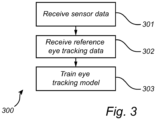
- Fig. 3 is a flow chart of an embodiment of this method 300.
- the eye tracking model is adapted to predict eye tracking data based on sensor data from a first eye tracking sensor.
- the eye tracking model is configured to predict or estimate eye tracking data using sensor data from the first eye tracking sensor, or using information derived from such sensor data.
- the eye tracking model may for example be regarded as a function (or a mapping) which receives sensor data from the first eye tracking sensor as input (and which optionally also receives further input data) and which provides predicted eye tracking data as output.
- the eye tracking model which is trained in the method 300 may for example be a machine learning (ML) based eye tracking model.
- the eye tracking model may for example be based on an artificial neural network, such as a convolutional neural network.
- the eye tracking model could also be a more traditional model, which may for example be trained by traditional optimization of values of a set of parameters.
- the method 300 comprises receiving 301 sensor data obtained by the first eye tracking sensor at a time instance (or at a point in time).
- the sensor data is received 301 after having been obtained (or generated) by the first eye tracking sensor at a certain time instance or point in time.
- the first eye tracking sensor may for example be an imaging device. However, as described above, several other types of eye tracking sensors may also be envisaged.
- the method 300 comprises receiving 302 reference eye tracking data for the time instance generated by an eye tracking system comprising a second eye tracking sensor.
- the reference eye tracking data is generated by the eye tracking system based on sensor data obtained by the second eye tracking sensor at the time instance (in other words, at the point in time when the received 301 sensor data was obtained by the first eye tracking sensor).
- the second eye tracking sensor may for example be an imaging device.
- the second eye tracking sensor is distinct from the first eye tracking sensor. In other words, the first and second eye tracking sensors do not coincide, but they could for example of a similar type.
- the method 300 comprises training 303 the eye tracking model based on the sensor data obtained by the first eye tracking sensor at the time instance and the generated reference eye tracking data.
- the training may for example comprise adapting values for one or more parameters of the eye tracking model.
- the sensor data received at step 301 and the sensor data on which the reference eye tracking data received at step 302 is based need not necessarily be obtained by the first and second eye tracking sensors at exactly the same time instance.
- these two sets of sensor data may be obtained by the respective eye tracking sensors at approximately the same time instance, but there may of course be a slight deviation or timing mismatch between these two sets of sensor data. It will be appreciated that as long as such a deviation is so small that the eye has not moved (or has not been redirected) too much during this very short time period, the step of training 303 the eye tracking model will not be significantly affected by the mismatch.
- Fig. 4 is a schematic overview of a system 400 for training an eye tracking model, according to an embodiment.
- the system 400 may for example perform the method 300 described above with reference to Fig. 3 .
- Eye tracking system 420 which comprises an eye tracking sensor 421 and means for analyzing the sensor data to generate eye tracking data, such as an estimated position of the eye 100 in space, or an estimated gaze point of the eye 100.
- Eye tracking data such as an estimated position of the eye 100 in space, or an estimated gaze point of the eye 100.
- You have a new eye tracking system 410 which comprises an eye tracking sensor 411, but the new eye tracking system is not yet able to generate accurate gaze tracking data based on sensor data from the eye tracking sensor 411.
- the software or algorithm employed in the old eye tracking system 420 is not that useful for the new eye tracking system 410 for a reason such as:
- the old eye tracking system 420 is employed to provide ground truth data for training of the new eye tracking system 410.
- the new eye tracking system 410 is equipped with an eye tracking model adapted to predict eye tracking data based on sensor data obtained by the eye tracking sensor 411.
- the method 300 described above with reference to Fig. 3 may then be employed for training the eye tracking model of the new eye tracking system 410, using the old eye tracking system 420 to generate reference eye tracking data.
- the eye tracking sensor 411 is an example of the first eye tracking sensor, which obtained the sensor data received at step 301
- the old eye tracking system 420 is an example of the eye tracking system, which generated the reference eye tracking data received at step 302.
- the eye tracking sensor 421 is an example of the second eye tracking system referred to in the method 300.
- the system 400 comprises processing circuitry 430 configured to perform the method 300 to train the eye tracking model of the new eye tracking system 410.
- the processing circuitry 430 may for example comprise one or more processors 431.
- the processor(s) 431 may for example be application-specific integrated circuits (ASIC) configured to perform a specific method (such as the method 300).
- ASIC application-specific integrated circuits
- the processor(s) 431 may be configured to execute instructions (for example in the form of a computer program) stored in one or more memories 432.
- Such one or more memories 432 may for example be comprised in the processing circuitry 430 of the system 400, or may be external to (for example located remotely from) the system 400.
- the one or more memories 432 may for example store instructions for causing the system 500 to perform the method 300.
- the processing circuitry 430 may be communicatively connected to the old eye tracking system 420 and the new eye tracking system 410 (or at least to the eye tracking sensor 411 in the new eye tracking system 410), for example via wired and/or wireless connections.
- the old eye tracking system 420 may for example be a PCCR-based eye tracking system.
- the reference eye tracking data received at step 302 in the method 300 may have been generated by the eye tracking system 420 based on an image position of a corneal reflection of an illuminator 422 at a known position in relation to the eye tracking sensor 421 (which in this case is an imaging device) and an image position of a pupil center.
- the old eye tracking system 420 may for example comprise more eye tracking sensors, or more advanced eye tracking sensors, or more illuminators than the new eye tracking system 410.
- the new eye tracking system 410 By training the new eye tracking system 410 using a more advanced eye tracking system 420, an eye tracking system 410 with relatively cheaper components could be obtained, which is able to perform almost as well as the more advanced eye tracking system 420.
- the eye tracking sensor 421 in the old eye tracking system 420 is an imaging device (such as a camera), and one or more illuminators 422-424 are provided for illuminating the eye 100.
- the eye tracking sensor 411 in the new eye tracking system 410 is also an imaging device.
- Light 428 from the illuminator 422 in the old eye tracking system 420 reaches the imaging device 421 in the old eye tracking system 420 via a reflection at the cornea of the eye 100.
- light 429 from the illuminator 422 in the old eye tracking system 420 may also reach the imaging device 411 in the new eye tracking system 420, which may cause interference in images captured by the imaging device 411 in the new eye tracking system 410.
- a filter 415 may therefore be employed to prevent light 429 from the illuminator 422 from reaching the imaging device 411.
- the old eye tracking system 420 comprises an illuminator 422 which outputs light 428 within a wavelength range for illuminating an eye 100, and the eye tracking sensor 421 of the old eye tracking system 420 provides sensor data based on light within the wavelength range.
- the eye tracking sensor 411 of the new eye tracking system 410 may be provided with a filter 415 for suppressing light within the wavelength range.
- Light emitted by the illuminator 422 may for example be light of a relatively long wave length, and the filter 415 may be a short pass filter. Alternatively, light emitted by the illuminator 422 may for example be light of a relatively short wave length, and the filter 415 may be a long pass filter. If light emitted by the illuminator 422 is not restricted to a certain wavelength range, a filter 426 may for example be provided in front of the illuminator 422 for suppressing light outside a certain wavelength range.
- the eye tracking sensor 421 in the old eye tracking system 420 may be provided with a filter 427 for suppressing light from the illuminator in the new eye tracking system 410.
- Light emitted by the illuminator 412 may for example be light of a relatively long wave length, and the filter 427 may be a short pass filter.
- light emitted by the illuminators 412 may for example be light of a relatively short wave length, and the filter 427 may be a long pass filter.
- a filter 415 may be provided in front of the illuminator 412 for suppressing light outside a certain wavelength range.
- the two eye tracking systems 410 and 420 are prevented from interfering with each other.
- the old eye tracking system 420 may employ light in a first wavelength range (for example around 940 nm), while the new eye tracking system employs light in a second wavelength range (for example about 850nm), which does not overlap the first wavelength range.
- the old eye tracking system 420 and/or the new eye tracking system 410 may comprise one or more illuminators.
- the illuminators may for example be infrared or near infrared illuminators, for example in the form of light emitting diodes (LEDs).
- LEDs light emitting diodes
- the old eye tracking system 420 may for example comprise a member 425 (for example a circuit board, such as a printed circuit board, PCB) at which the eye tracking sensor 421 and the illuminators 422-424 are mounted.
- the new eye tracking system 410 may for example comprise a member 414 (for example a circuit board, such as a PCB) at which the eye tracking sensor 411 and the illuminators 412-413 are mounted.
- system 400 need not necessarily comprise all those components shown in Fig. 4 .
- the system 400 could comprise only the processing circuitry 431, and the rest of the components shown in Fig 4 could be regarded as external to the system 400.
- the system 400 comprises the eye tracking system 420 employed to generate the reference eye tracking data received at step 302 in the method 300.
- the system 400 comprises the eye tracking sensor 411 employed to obtain the sensor data received at step 301 in the method 300.
- the eye tracking system 420 and the eye tracking system 410 may for example be provided in the form of two separate units or devices, which may for example be mountable at a display device for performing eye tracking.
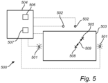
- Fig. 5 is a schematic overview of an example eye tracking system 500.
- the old eye tracking system 420 and/or the new eye tracking system 410 in Fig. 4 may for example be of the type described below with reference to Fig. 5 .
- the system 500 comprises one or more illuminators 501 for illuminating the eye 100 and one or more imaging devices 502 for capturing images of the eye 100 while the eye 100 looks at a display 503.
- the system 500 also comprises processing circuitry 504 configured to estimate where the eye 100 is located and/or where the eye 100 is looking.
- the processing circuitry 504 may for example estimate eye tracking data such as a gaze direction (or gaze vector) of the eye 100 (corresponding to a direction of the visual axis 109), or a gaze point 508 of the eye 100 at the display 503.
- the eye tracking system 500 may for example be a gaze tracking system.
- the processing circuitry 504 is communicatively connected to the illuminators 501 and the imaging devices 502, for example via a wired or wireless connection.
- the processing circuitry 504 may also be communicatively connected to the display 503, for example for controlling (or triggering) the display 503 to show test stimulus points for calibration of the eye tracking system 500.
- Fig. 5 shows example illuminators 501 located at either side of the display 503, but the illuminators 501 could be located elsewhere.
- Fig. 5 shows example imaging devices 502 located above the display 503, but the imaging devices 502 could be located elsewhere, for example below the display 503.
- the display 503 may for example be a liquid-crystal display (LCD) or a LED display. However, other types of displays may also be envisaged.
- the display may 503 may for example be flat or curved.
- the display 503 may for example be a TV screen, a computer screen, or may be part of a head-mounted device (HMD) such as a virtual reality (VR) or augmented reality (AR) device.
- HMD head-mounted device
- VR virtual reality
- AR augmented reality
- the display 503 may for example be placed in front of one of the user's eyes. In other words, separate displays 503 may be employed for the left and right eyes.
- Separate eye tracking equipment such as illuminators 501 and imaging devices 502 may for example be employed for the left and right eyes.
- the processing circuitry 504 may be employed for eye tracking for both eyes, or there may be separate processing circuitry 504 for the left and right eyes.
- the eye tracking system 500 may for example perform eye tracking for the left and right eyes separately, and may then determine a combined gaze point as an average of the gaze points for the left and right eyes.
- the processing circuitry 504 may for example comprise one or more processors 506.
- the processor(s) 506 may for example be application-specific integrated circuits (ASIC) configured to perform a specific eye tracking method.
- ASIC application-specific integrated circuits
- the processor(s) 506 may configured to execute instructions (for example in the form of a computer program) stored in one or more memories 507.
- Such a memory 507 may for example be comprised in the processing circuitry 504 of the eye tracking system 500, or may be external to (for example located remotely from) the eye tracking system 500.
- the memory 507 may store instructions for causing the eye tracking system 500 to perform an eye tracking method.
- the eye tracking system 500 described above with reference to Fig. 5 is provided as an example, and that many other eye tracking systems may be envisaged.
- the illuminators 501 and/or the imaging devices 502 need not necessarily be regarded as part of the eye tracking system 500.
- the eye tracking system 500 may for example consist only of the processing circuitry 504. There are even eye tracking systems that do not employ illuminators at all. Further, some eye tracking systems employ other types of eye tracking sensors than imaging devices. In other words, the eye tracking system 500 could employ other types of sensor data than images to perform eye tracking.
- the display 503 may for example be comprised in the eye tracking system 500, or may be regarded as separate from the eye tracking system 500.
- the method 300 described above with reference to Fig. 3 may for example receive data passively at the steps 301 and 302 from the first eye tracking sensor (exemplified in Fig. 4 by the sensor 411) and the eye tracking system (exemplified in Fig. 4 by the system 420).
- the method 300 may further comprise using the first eye tracking sensor to obtain sensor data at the time instance (in other words, the sensor data received at step 301), and/or using the eye tracking system to generate the reference eye tracking data for the time instance (in other words, the eye tracking data received at step 302).
- the method 300 may actively use the first eye tracking sensor 411 and the eye tracking system 420, for example by controlling (or instructing) them to provide the necessary data.
- Fig. 6 is a flow chart of method 600 for training an eye tracking model, including such explicit use of the first eye tracking sensor 411 and the eye tracking system 420, according to an embodiment.
- the method 600 is described below with reference to the eye tracking sensor 411 and the eye tracking system 420 shown in Fig. 4 , it will be appreciated that a different eye tracking sensor and/or a different eye tracking system may be employed in the method 600.
- the method 600 comprises using 601 the first eye tracking sensor 411 to obtain sensor data at a time instance. This corresponds to the sensor data received at step 301 in the method 300.
- the method 600 comprises using 602 an eye tracking system 420 to generate reference eye tracking data for the time instance.
- the eye tracking system 420 comprises a second eye tracking sensor 421.
- the reference eye tracking data is generated by the eye tracking system 420 based on sensor data obtained by the second eye tracking sensor 421 at the time instance. In other words, the generated reference eye tracking data corresponds to the generated reference eye tracking data received at step 302 in the method 300.
- the method 600 comprises training 303 the eye tracking model based on the sensor data obtained by the first eye tracking sensor 411 at the time instance and the generated reference eye tracking data.
- the method 600 comprises the same training step 303 as the method 300.
- the eye tracking data predicted by the eye tracking model in the method 300 or the method 600 indicates a predicted gaze point of an eye
- the generated reference eye tracking data (received at step 302 of the method 300 or obtained at step 602 of the method 600) indicates a reference gaze point of the eye.
- the predicted gaze point and the reference gaze point may for example be gaze points at a display. This is exemplified in Fig. 5 where a predicted gaze point 508 and a reference gaze point 505 are shown at the display 503. A distance 509 between these two gaze points is also shown in Fig. 5
- the eye tracking data predicted by the eye tracking model in the method 300 or the method 600 indicates a predicted gaze ray of an eye
- the generated reference eye tracking data (received at step 302 or obtained at step 602) indicates a reference gaze ray of the eye.
- Fig. 7 shows two example gaze rays.
- a first gaze ray 701 starts at a first estimated eye position 702 and is directed along a first gaze vector 703.
- a second gaze ray 704 starts at a second estimated eye position 705 and is directed along a second gaze vector 706.
- the first gaze ray 701 may for example be a gaze ray predicted by the eye tracking model in the method 300 or the method 600
- the second gaze ray 704 may for example be a reference gaze ray indicated by the generated reference eye tracking data received at step 302 in the method 300 or obtained at step 602 in the method 300.
- Fig. 7 also shows that a deviation between the gaze rays 701 and 704 may for example be measured via an angle 707 formed between the gaze vectors 703 and 706. A distance 708 may also be formed between the estimated eye positions 702 and 705. Fig. 7 also shows that sensor data (such as an image 709 of an eye) may be employed by an eye tracking model 710 to predict eye tracking data such as the gaze ray 701.
- the eye tracking data predicted by the eye tracking model in the method 300 or the method 600 indicates a predicted position of an eye in space
- the generated reference eye tracking data (received at step 302 or obtained at step 602) indicates a reference position of the eye in space.
- the gaze origin 702 of the first gaze ray 701 in Fig. 7 may be an eye position predicted by the eye tracking model in the method 300 or the method 600.
- the gaze origin 705 of the second gaze ray 704 in Fig. 7 may be a reference eye position indicated by the generated reference eye tracking data received at step 302 in the method 300 or obtained at step 602 in the method 600.
- Fig. 8 shows a scheme for how an eye tracking model may be trained in the methods 300 and 600 described above with reference to Figs. 3 and 6 , according to an embodiment.
- the step of training 303 the eye tracking model comprises:
- an objective function (such as a cost function or loss function) is employed to evaluate whether or not the predictions made by the eye tracking model seem to be compatible with the reference eye tracking data.
- the eye tracking model is updated 803 to improve its ability to make accurate predictions.
- the step 802 of applying the objective function may include inserting the eye tracking data predicted by the eye tracking model for the time instance and the generated reference eye tracking data into the objective function. It will be appreciated that the step 802 of applying the objective function may for example also comprise inserting additional data into the objective function.
- the step 803 of updating the eye tracking model may for example comprise modifying a value of at least one parameter of the eye tracking model.
- the objective function is a cost function (or a loss function), which is supposed to have a low value if the prediction 801 is accurate, then the eye tracking model may for example be modified for reducing a value of the objective function (for example via graduate descent).
- the objective function is a function that should be maximized (for example if the objective function is a cost function multiplied by -1), then the eye tracking model may for example be modified for increasing a value of the objective function.
- the step of applying 802 the objective function comprises forming a distance between a predicted gaze point indicated by the predicted eye tracking data for the time instance and a reference gaze point indicated by the generated reference eye tracking data. This is exemplified in Fig. 5 where a distance 509 between a predicted gaze point 508 and a reference gaze point 505 is illustrated. If the prediction provided by the eye tracking model is accurate, this distance 509 should be small.
- the step of applying 802 the objective function comprises forming a deviation between a predicted gaze ray indicated by the predicted eye tracking data for the time instance and a reference gaze ray indicated by the generated reference eye tracking data.
- a predicted gaze ray indicated by the predicted eye tracking data for the time instance corresponds to a gaze ray predicted by the eye tracking model in the method 300 or the method 600
- the second gaze ray 704 corresponds to a reference gaze ray indicated by the generated reference eye tracking data received at step 302 in the method 300 or obtained at step 602 in the method 600.
- the deviation between the predicted gaze ray 701 and the reference gaze ray 704 may for example be expressed in form of the angle 707 formed between the respective gaze vectors 703 and 706. If the prediction provided by the eye tracking model is accurate, this angle 707 should be small.
- the step of applying 802 the objective function comprises forming a distance between a predicted eye position indicated by the predicted eye tracking data for the time instance and a reference eye position indicated by the generated reference eye tracking data.
- a predicted eye position indicated by the predicted eye tracking data for the time instance corresponds to an eye position predicted by the eye tracking model in the method 300 or the method 600
- the gaze origin 705 of the second gaze ray 704 corresponds to a reference eye position indicated by the generated reference eye tracking data received at step 302 in the method 300 or obtained at step 602 in the method 600. If the prediction provided by the eye tracking model is accurate, the distance 708 between the predicted eye position 702 and the reference eye position 705 should be small.
- Fig. 9 shows a scheme for how training of the eye tracking model in the methods 300 and 600 described above with reference to Figs. 6 and 7 may be performed, according to an embodiment.
- the step 303 of training the eye tracking model comprises predicting 901 eye tracking data for the time instance using the eye tracking model and the sensor data obtained by the first eye tracking sensor at the time instance.
- a check 902 is performed to see whether a deviation between the eye tracking data predicted 901 by the eye tracking model for the time instance and the generated reference eye tracking data (which is received at step 302 or generated at step 602) exceeds a threshold.
- the scheme/method proceeds by training 903 the eye tracking model based on the eye tracking data predicted by the eye tracking model for the time instance and the generated reference eye tracking data. If, on the other hand, the deviation does not exceed the threshold, then the eye tracking data predicted by the eye tracking model for the time instance and the generated reference eye tracking data may not be employed for training of the eye tracking model (as indicated by the step 904 in Fig. 9 ).
- the predicted gaze tracking data checks out with (or matches) the reference gaze tracking data, there may be no need to train the eye tracking model. If, on the other hand, it is detected that the predicted eye tracking data deviates from the reference eye tracking data, then training may be needed.
- the eye tracking model may for example perform well for some types of input data (or for some scenarios or user activities) but worse for other types of input data.
- the scheme described above with reference to Fig. 9 allows the eye tracking model to be trained for such types of input data where further training is actually needed, rather than training blindly for all types of input data.
- the deviation employed at step 902 in Fig. 9 may for example be a deviation between a predicted gaze point and a reference gaze point, a deviation between a predicted gaze ray and a reference gaze ray, or a deviation between a predicted eye position and a reference eye position.
- the threshold employed at step 902 in Fig. 9 may for example be predefined. However, embodiments may also be envisaged in which this threshold may be changed or modified.
- Fig. 10 shows a method 1000 of training an eye tracking model, according to an embodiment.
- the method 1000 is similar to the method 300 described above with reference to Fig. 3 , but further comprises using 1001 the eye tracking system (exemplified in Fig. 4 by the eye tracking system 420) to detect a certain trigger action of an eye 100.
- the certain trigger action comprises:
- the step 301 of receiving of the sensor data obtained by the first eye tracking sensor at the time instance (which may be referred to as a data acquisition step) and/or the step 303 of training of the eye tracking model may be performed in response to detection of the certain trigger action of the eye.
- the data acquisition step 301 and the training step 303 may be performed. If, on the other hand, the trigger action is not detected, then the data acquisition step 301 and the training step 303 may be skipped, or the data acquisition step 301 may be performed and the training step 303 may skipped.
- the method 1000 described above with reference to Fig. 10 allows the eye tracking model to be trained to handle certain scenarios better, such as fixations, saccades or smooth pursuits, rather than training the eye tracking model blindly for all types of input data. Certain scenarios may for example be particularly difficult for the eye tracking model to handle, or some scenarios may require better accuracy than other scenarios. It may therefore be useful to train the model specifically for such scenarios.
- the training of the eye tracking model may for example be based on training data collected in connection with the trigger action, such as during the trigger action, and/or shortly before the trigger action, and/or shortly after the trigger action.
- the trigger action may for example be detected by analyzing eye tracking data received from the eye tracking system, or an explicit indication of the trigger action may for example be received from the eye tracking system.
- the method 1000 described above with reference to Fig. 10 is provided in the context of the method 300 described above with reference to Fig. 3 . It will be appreciated that the method 1000 could easily be modified to instead be employed in the context of the method 600 described above with reference to Fig 6 . In other words, the step 601 and/or the step 303 in the method 600 may be made conditional upon detection of a certain trigger action of the eye 100, just like the steps 301 and 303 from the method 300.
- Fig. 11 is a flow chart of a method 1100 for training an eye tracking model, according to an embodiment.
- the method 1100 is similar to the method 300 described above with reference to Fig. 3 , but the method 1100 includes new steps 1101-1102, and the step 303 is expressed in terms of a new step 1103.
- the eye tracking model is one of several eye tracking models.
- the eye tracking models are associated with respective potential users or persons.
- the method 1100 comprises detecting 1101 presence of a user (or of a person), and selecting 1102 the eye tracking model associated with the user (or person). Presence of the user may for example be detected 1101 by the eye tracking system, or via the first eye tracking sensor. Presence of the user may for example be detected via biometric data (such as facial recognition, or a finger or, or an iris scan) or via some kind of credential (such as a smart card or a wireless sensor tag).
- the eye tracking model may for example be selected 1102 from a database of potential users and their respective eye tracking models.
- the method 1100 comprises training 1103 the selected eye tracking model based on the sensor data obtained by the first eye tracking sensor at the time instance (in other words, the sensor data received at step 301) and the generated reference eye tracking data (in other words, reference eye tracking data received at step 302).
- the method 1100 described above with reference to Fig. 11 is provided in the context of the method 300 described above with reference to Fig. 3 . It will be appreciated that the method 1100 could easily be modified to instead be employed in the context of the method 600 described above with reference to Fig 6 . More specifically, the step 301-302 in the method 1100 could for example be replaced by the steps 601-602 from the method 600.
- the method 300 described above with reference to Fig. 3 may be extended to perform training for sensor data from a sequence of time instances. More specifically, the method 300 may comprise:
- data for the time instances may be employed for training the eye tracking model, or may be stored for use in training later on.
- the training data may for example be stored in a database or may be uploaded to the cloud.
- Training of the eye tacking data may for example be performed at a remote location from where the training data was collected.
- Training of the eye tracking model may for example be performed gradually as training data becomes available. Alternatively, plenty a training data may be collected first and training may then be performed using the collected training data. After the eye tracking model has been sufficiently trained, it may for example be employed in an eye tracking system to predict eye tracking data in real time.
- the methods and schemes described above with reference to Figs. 3-11 represent a first aspect of the present disclosure.
- the system 400 described above with reference to Fig. 4 represents a second aspect of the present disclosure.
- the system 400 (or the processing circuitry 430 of the system 400) may for example be configured to perform the method of any of the embodiments of the first aspect described above.
- the system 400 may for example be configured to perform the method 300 described above with reference to Fig. 3 or the method 600 described above with reference to Fig. 6 .
- the system 400 may for example comprise processing circuitry 430 (or one or more processors 431) and one or more memories 432, the one or more memories 432 containing instructions executable by the processing circuitry 430 (or one or more processors 431), whereby the system 400 is operable to perform the method of any of the embodiments of the first aspect disclosed herein.
- system 400 need not necessarily comprise all the elements shown in Fig. 4 .
- a third aspect of the present disclosure is represented by embodiments of a non-transitory computer-readable storage medium 432 storing instructions which, when executed by the system 400 (or by processing circuitry 430 of the system 400), cause the system 400 to perform the method of any of the embodiments of the first aspect described above (such as the method 300 described above with reference to Fig. 3 , or the method 600 described above with reference to Fig. 6 ).
- the storage medium 432 need not necessarily be comprised in the system 400.
- processing circuitry 430 may comprise a combination of one or more of a microprocessor, controller, microcontroller, central processing unit, digital signal processor, application-specific integrated circuit, field programmable gate array, or any other suitable computing device, resource, or combination of hardware, software and/or encoded logic operable to provide computer functionality, either alone or in conjunction with other computer components (such as a memory or storage medium).
- a memory or storage medium 432 may comprise any form of volatile or non-volatile computer readable memory including, without limitation, persistent storage, solid-state memory, remotely mounted memory, magnetic media, optical media, random access memory (RAM), read-only memory (ROM), mass storage media (for example, a hard disk), removable storage media (for example, a flash drive, a Compact Disk (CD) or a Digital Video Disk (DVD)), and/or any other volatile or non-volatile, non-transitory device readable and/or computer-executable memory devices that store information, data, and/or instructions that may be used by a processor or processing circuitry.
- volatile or non-volatile computer readable memory including, without limitation, persistent storage, solid-state memory, remotely mounted memory, magnetic media, optical media, random access memory (RAM), read-only memory (ROM), mass storage media (for example, a hard disk), removable storage media (for example, a flash drive, a Compact Disk (CD) or a Digital Video Disk (DVD)), and/or
Landscapes
- Engineering & Computer Science (AREA)
- Theoretical Computer Science (AREA)
- Physics & Mathematics (AREA)
- General Physics & Mathematics (AREA)
- General Engineering & Computer Science (AREA)
- Radar, Positioning & Navigation (AREA)
- Remote Sensing (AREA)
- Human Computer Interaction (AREA)
- Data Mining & Analysis (AREA)
- Computer Networks & Wireless Communication (AREA)
- Multimedia (AREA)
- Artificial Intelligence (AREA)
- Computer Vision & Pattern Recognition (AREA)
- Evolutionary Biology (AREA)
- Evolutionary Computation (AREA)
- Bioinformatics & Computational Biology (AREA)
- Bioinformatics & Cheminformatics (AREA)
- Life Sciences & Earth Sciences (AREA)
- Ophthalmology & Optometry (AREA)
- General Health & Medical Sciences (AREA)
- Health & Medical Sciences (AREA)
- Signal Processing (AREA)
- Optics & Photonics (AREA)
- Image Analysis (AREA)
- Eye Examination Apparatus (AREA)
- Measurement Of Velocity Or Position Using Acoustic Or Ultrasonic Waves (AREA)
- Radar Systems Or Details Thereof (AREA)
Claims (8)
- Verfahren (300) zum Trainieren eines Augenverfolgungsmodells (710), wobei das Augenverfolgungsmodell (710) angepasst ist, um Augenverfolgungsdaten basierend auf Sensordaten (709) von einem ersten Augenverfolgungssensor (411) eines neuen Augenverfolgungssystems (410) zu schätzen, wobei der erste Augenverfolgungssensor (411) eingerichtet ist, um ein Auge (100) zu überwachen, das Verfahren umfassend:Empfangen (301) von Sensordaten, wobei die Sensordaten zu einem Zeitpunkt durch den ersten Augenverfolgungssensor (411) erhalten werden;gekennzeichnet durch:Empfangen (302) von Referenzaugenverfolgungsdaten für den Zeitpunkt, die durch ein altes Augenverfolgungssystem (420) generiert werden, umfassend einen zweiten Augenverfolgungssensor (421), der eingerichtet ist, um das Auge (100) zu überwachen, wobei die Referenzaugenverfolgungsdaten durch das alte Augenverfolgungssystem (420) basierend auf Sensordaten generiert werden, die durch den zweiten Augenverfolgungssensor (421) zu dem Zeitpunkt erhalten werden; undTrainieren (303) des Augenverfolgungsmodells (710) basierend auf den Sensordaten, die durch den ersten Augenverfolgungssensor (411) zu dem Zeitpunkt erhalten werden, und den generierten Referenzaugenverfolgungsdaten für den Zeitpunkt, wobei das Trainieren des Augenverfolgungsmodells (710) umfasst:Schätzen (801) von Augenverfolgungsdaten für den Zeitpunkt unter Verwendung des Augenverfolgungsmodells (710) und der Sensordaten, die durch den ersten Augenverfolgungssensor (411) zu dem Zeitpunkt erhalten werden;Anwenden (802) einer Zielfunktion auf mindestens die Augenverfolgungsdaten, die durch das Augenverfolgungsmodell (710) für den Zeitpunkt geschätzt werden, und die generierten Referenzaugenverfolgungsdaten für den Zeitpunkt; undAktualisieren (803) des Augenverfolgungsmodells (710).
- Verfahren nach Anspruch 1, wobei das Anwenden (802) der Zielfunktion auf mindestens die Augenverfolgungsdaten, die durch das Augenverfolgungsmodell (710) für den Zeitpunkt geschätzt werden, und die generierten Referenzaugenverfolgungsdaten, umfasst:Bestimmen einer Distanz (509) zwischen einem geschätzten Blickpunkt (508), der durch die geschätzten Augenverfolgungsdaten für den Zeitpunkt angegeben wird, und einem Referenzblickpunkt (505), der durch die generierten Referenzaugenverfolgungsdaten für den Zeitpunkt angegeben wird; und/oderMessen einer Abweichung (707) zwischen einem geschätzten Blickstrahl (701), der durch die geschätzten Augenverfolgungsdaten für den Zeitpunkt angegeben wird, und einem Referenzblickstrahl (704), der durch die generierten Referenzaugenverfolgungsdaten für den Zeitpunkt angegeben wird; und/oderBestimmen einer Distanz (708) zwischen einer geschätzten Augenposition (702), die durch die geschätzten Augenverfolgungsdaten für den Zeitpunkt angegeben wird, und einer Referenzaugenposition (705), die durch die generierten Referenzaugenverfolgungsdaten für den Zeitpunkt angegeben wird.
- Verfahren nach einem der Ansprüche 1 bis 2, wobei das Trainieren des Augenverfolgungsmodells (710) umfasst:
als Reaktion auf eine Abweichung (509, 707, 708) zwischen den Augenverfolgungsdaten, die durch das Augenverfolgungsmodell (710) für den genannten Zeitpunkt geschätzt werden, und den generierten Referenzaugenverfolgungsdaten für den genannten Zeitpunkt, der einen Schwellenwert überschreitet, Trainieren (903) des Augenverfolgungsmodells (710) basierend auf den Augenverfolgungsdaten, die durch das Augenverfolgungsmodell (710) für den genannten Zeitpunkt geschätzt werden, und den generierten Referenzaugenverfolgungsdaten für den genannten Zeitpunkt. - Verfahren nach einem der vorstehenden Ansprüche, umfassend:Empfangen von Sensordaten, die durch den ersten Augenverfolgungssensor (411) zu einer Abfolge von Zeitpunkten erhalten werden;Empfangen von Referenzaugenverfolgungsdaten für die Abfolge von Zeitpunkten, die durch das alte Augenverfolgungssystem (420) generiert werden, wobei die Referenzaugenverfolgungsdaten für die Abfolge von Zeitpunkten durch das alte Augenverfolgungssystem (420) basierend auf Sensordaten generiert werden, die durch den zweiten Augenverfolgungssensor (421) zu der Abfolge von Zeitpunkten erhalten werden; undTrainieren des Augenverfolgungsmodells (710) basierend auf den Sensordaten, die durch den ersten Augenverfolgungssensor (411) zu der Abfolge von Zeitpunkten erhalten werden, und der generierten Referenzaugenverfolgungsdaten für die Abfolge von Zeitpunkten, und/oderSpeichern der Sensordaten, die durch den ersten Augenverfolgungssensor (411) zu der Abfolge von Zeitpunkten erhalten werden, und der generierten Referenzaugenverfolgungsdaten für die Abfolge von Zeitpunkten.
- System (400) zum Trainieren eines Augenverfolgungsmodells (710), das System (400) umfassend
erster Augenverfolgungssensor (411), wobei das Augenverfolgungsmodell (710) angepasst ist, um Augenverfolgungsdaten basierend auf Sensordaten (709) von dem ersten Augenverfolgungssensor (411) eines neuen Augenverfolgungssystems (410) zu schätzen, wobei der erste Augenverfolgungssensor (411) eingerichtet ist, um ein Auge (100) zu überwachen, das System (400) umfassend eine Verarbeitungsschaltung (430), die konfiguriert ist zum:Empfangen von Sensordaten, wobei die Sensordaten zu einem Zeitpunkt durch den ersten Augenverfolgungssensor (411) erhalten werden;dadurch gekennzeichnet, dass die Verarbeitungsschaltung (430) ferner konfiguriert ist zum:Empfangen von Referenzaugenverfolgungsdaten für den genannten Zeitpunkt, die durch ein altes Augenverfolgungssystem (420) generiert werden, umfassend einen zweiten Augenverfolgungssensor (421), der eingerichtet ist, um das Auge (100) zu überwachen, wobei die Referenzaugenverfolgungsdaten durch das alte Augenverfolgungssystem (420) basierend auf Sensordaten generiert werden, die durch den zweiten Augenverfolgungssensor (421) zu dem genannten Zeitpunkt erhalten werden; undTrainieren des Augenverfolgungsmodells (710) basierend auf den Sensordaten, die durch den ersten Augenverfolgungssensor (411) zu dem Zeitpunkt erhalten werden, und den generierten Referenzaugenverfolgungsdaten für den Zeitpunkt, wobei das Trainieren des Augenverfolgungsmodells (710) umfasst:Schätzen (801) von Augenverfolgungsdaten für den genannten Zeitpunkt unter Verwendung des Augenverfolgungsmodells (710) und der Sensordaten, die durch den ersten Augenverfolgungssensor (411) zu dem genannten Zeitpunkt erhalten werden;Anwenden (802) einer Zielfunktion auf mindestens die Augenverfolgungsdaten, die durch das Augenverfolgungsmodell (710) für den genannten Zeitpunkt geschätzt werden, und die generierten Referenzaugenverfolgungsdaten; undAktualisieren (803) des Augenverfolgungsmodells (710). - System (400) nach Anspruch 5, wobei die Verarbeitungsschaltung (430) konfiguriert ist, um das Augenverfolgungsmodell (710) mindestens zu trainieren durch:
als Reaktion auf eine Abweichung (509, 707, 708) zwischen den Augenverfolgungsdaten, die durch das Augenverfolgungsmodell (710) für den genannten Zeitpunkt geschätzt werden, und den generierten Referenzaugenverfolgungsdaten für den genannten Zeitpunkt, der einen Schwellenwert überschreitet, Trainieren des Augenverfolgungsmodells (710) basierend auf den Augenverfolgungsdaten, die durch das Augenverfolgungsmodell (710) für den Zeitpunkt geschätzt werden, und den generierten Referenzaugenverfolgungsdaten für den Zeitpunkt. - System (400) nach einem der Ansprüche 5 bis 6,wobei der erste Augenverfolgungssensor (411) eine bildgebende Vorrichtung ist und/oder wobei der zweite Augenverfolgungssensor (421) eine bildgebende Vorrichtung ist und/oderwobei das Augenverfolgungssystem (400) eine Beleuchtungseinrichtung (422, 423, 424) umfasst, die konfiguriert ist, um Licht (428, 429) innerhalb eines Wellenlängenbereichs zum Beleuchten des Auges (100) auszugeben, der zweite Augenverfolgungssensor (421) konfiguriert ist, um Sensordaten basierend auf Licht innerhalb des Wellenlängenbereichs bereitzustellen, wobei der erste Augenverfolgungssensor (411) mit einem Filter (415) zum Unterdrücken von Licht innerhalb des Wellenlängenbereichs versehen ist.
- Nichtflüchtiges computerlesbares Speichermedium (432), das Anweisungen zum Trainieren eines Augenverfolgungsmodells (710) speichert, wobei das Augenverfolgungsmodell (710) angepasst ist, um Augenverfolgungsdaten basierend auf Sensordaten (709) von einem ersten Augenverfolgungssensor (411) eines neuen Augenverfolgungssystems (410) zu schätzen, wobei der erste Augenverfolgungssensor (411) eingerichtet ist, um ein Auge (100) zu überwachen, wobei die Anweisungen, wenn sie durch ein System (400) ausgeführt werden, das System (400) veranlassen zum:Empfangen von Sensordaten, wobei die Sensordaten zu einem Zeitpunkt durch den ersten Augenverfolgungssensor (411) erhalten werden;dadurch gekennzeichnet, dass die Anweisungen, wenn sie durch ein System (400) ausgeführt werden, ferner das System (400) veranlassen zum:Empfangen von Referenzaugenverfolgungsdaten für den Zeitpunkt, die durch ein altes Augenverfolgungssystem (420) generiert werden, umfassend einen zweiten Augenverfolgungssensor (421), der eingerichtet ist, um das Auge (100) zu überwachen, wobei die Referenzaugenverfolgungsdaten durch das alte Augenverfolgungssystem (420) basierend auf Sensordaten generiert werden, die durch den zweiten Augenverfolgungssensor (421) zu dem Zeitpunkt erhalten werden; undTrainieren des Augenverfolgungsmodells (710) basierend auf den Sensordaten, die durch den ersten Augenverfolgungssensor (411) zu dem Zeitpunkt erhalten werden, und den generierten Referenzaugenverfolgungsdaten für den Zeitpunkt, wobei das Trainieren des Augenverfolgungsmodells (710) umfasst:Schätzen (801) von Augenverfolgungsdaten für den Zeitpunkt unter Verwendung des Augenverfolgungsmodells (710) und der Sensordaten, die durch den ersten Augenverfolgungssensor (411) zu dem Zeitpunkt erhalten werden;Anwenden (802) einer Zielfunktion auf mindestens die Augenverfolgungsdaten, die durch das Augenverfolgungsmodell (710) für den Zeitpunkt geschätzt werden, und die generierten Referenzaugenverfolgungsdaten; undAktualisieren (803) des Augenverfolgungsmodells (710).
Applications Claiming Priority (2)
| Application Number | Priority Date | Filing Date | Title |
|---|---|---|---|
| SE1950387A SE543273C2 (en) | 2019-03-29 | 2019-03-29 | Training an eye tracking model |
| EP20166411.7A EP3716021B1 (de) | 2019-03-29 | 2020-03-27 | Training eines augenverfolgungsmodells |
Related Parent Applications (2)
| Application Number | Title | Priority Date | Filing Date |
|---|---|---|---|
| EP20166411.7A Division EP3716021B1 (de) | 2019-03-29 | 2020-03-27 | Training eines augenverfolgungsmodells |
| EP20166411.7A Division-Into EP3716021B1 (de) | 2019-03-29 | 2020-03-27 | Training eines augenverfolgungsmodells |
Publications (2)
| Publication Number | Publication Date |
|---|---|
| EP4083756A1 EP4083756A1 (de) | 2022-11-02 |
| EP4083756B1 true EP4083756B1 (de) | 2024-10-30 |
Family
ID=70056996
Family Applications (3)
| Application Number | Title | Priority Date | Filing Date |
|---|---|---|---|
| EP20166411.7A Active EP3716021B1 (de) | 2019-03-29 | 2020-03-27 | Training eines augenverfolgungsmodells |
| EP22176897.1A Active EP4083756B1 (de) | 2019-03-29 | 2020-03-27 | Training eines augenverfolgungsmodells |
| EP22176896.3A Active EP4083755B1 (de) | 2019-03-29 | 2020-03-27 | Training eines augenverfolgungsmodells |
Family Applications Before (1)
| Application Number | Title | Priority Date | Filing Date |
|---|---|---|---|
| EP20166411.7A Active EP3716021B1 (de) | 2019-03-29 | 2020-03-27 | Training eines augenverfolgungsmodells |
Family Applications After (1)
| Application Number | Title | Priority Date | Filing Date |
|---|---|---|---|
| EP22176896.3A Active EP4083755B1 (de) | 2019-03-29 | 2020-03-27 | Training eines augenverfolgungsmodells |
Country Status (5)
| Country | Link |
|---|---|
| US (2) | US11386290B2 (de) |
| EP (3) | EP3716021B1 (de) |
| CN (2) | CN111753628B (de) |
| ES (3) | ES2926953T3 (de) |
| SE (1) | SE543273C2 (de) |
Families Citing this family (2)
| Publication number | Priority date | Publication date | Assignee | Title |
|---|---|---|---|---|
| CN113537295B (zh) * | 2021-06-22 | 2023-10-24 | 北京航空航天大学 | 基于离群点引导的视线估计跨场景适配方法和装置 |
| CN119234255A (zh) * | 2022-05-20 | 2024-12-31 | 苹果公司 | 用于同时进行眼睛特征跟踪和眼睛模型更新的方法、系统和装置 |
Family Cites Families (26)
| Publication number | Priority date | Publication date | Assignee | Title |
|---|---|---|---|---|
| US6659611B2 (en) * | 2001-12-28 | 2003-12-09 | International Business Machines Corporation | System and method for eye gaze tracking using corneal image mapping |
| US8299979B2 (en) * | 2003-05-14 | 2012-10-30 | Broadcom Corporation | Integral eye-path alignment on telephony and computer video devices using two or more image sensing devices |
| TW200842733A (en) * | 2007-04-17 | 2008-11-01 | Univ Nat Chiao Tung | Object image detection method |
| JP5719170B2 (ja) * | 2007-09-21 | 2015-05-13 | プレイデータ エルエルシー | 物体の位置及び運動検出システム、及び方法 |
| US8447128B2 (en) * | 2008-04-07 | 2013-05-21 | Fujifilm Corporation | Image processing system |
| JP5429445B2 (ja) * | 2008-04-08 | 2014-02-26 | 富士フイルム株式会社 | 画像処理システム、画像処理方法、およびプログラム |
| US8255827B2 (en) * | 2009-01-26 | 2012-08-28 | Microsoft Corporation | Dynamic feature presentation based on vision detection |
| US8553936B2 (en) * | 2009-03-03 | 2013-10-08 | The Ohio State University | Gaze tracking measurement and training system and method |
| US20120105486A1 (en) * | 2009-04-09 | 2012-05-03 | Dynavox Systems Llc | Calibration free, motion tolerent eye-gaze direction detector with contextually aware computer interaction and communication methods |
| JP5704829B2 (ja) | 2010-03-25 | 2015-04-22 | ユニ・チャーム株式会社 | ポリ乳酸系エアスルー不織布の製造方法、及びポリ乳酸系エアスルー不織布 |
| US8593375B2 (en) * | 2010-07-23 | 2013-11-26 | Gregory A Maltz | Eye gaze user interface and method |
| US9557812B2 (en) * | 2010-07-23 | 2017-01-31 | Gregory A. Maltz | Eye gaze user interface and calibration method |
| US8885882B1 (en) * | 2011-07-14 | 2014-11-11 | The Research Foundation For The State University Of New York | Real time eye tracking for human computer interaction |
| ES2620762T3 (es) * | 2011-10-27 | 2017-06-29 | Tobii Ab | Gestión de potencia en un sistema de rastreo ocular |
| US8913789B1 (en) * | 2012-01-06 | 2014-12-16 | Google Inc. | Input methods and systems for eye positioning using plural glints |
| US9004687B2 (en) * | 2012-05-18 | 2015-04-14 | Sync-Think, Inc. | Eye tracking headset and system for neuropsychological testing including the detection of brain damage |
| KR101979669B1 (ko) * | 2012-07-13 | 2019-05-17 | 삼성전자주식회사 | 이미지 내 사용자의 시선 보정 방법, 기계로 읽을 수 있는 저장 매체 및 통신 단말 |
| US9480397B2 (en) * | 2013-09-24 | 2016-11-01 | Sony Interactive Entertainment Inc. | Gaze tracking variations using visible lights or dots |
| US20150102981A1 (en) * | 2013-10-11 | 2015-04-16 | Microsoft Corporation | Eye tracking |
| EP3076948B1 (de) | 2013-12-06 | 2020-11-18 | Allergan, Inc. | Intrakamerales implantat zur behandlung von augenleiden |
| US9489739B2 (en) * | 2014-08-13 | 2016-11-08 | Empire Technology Development Llc | Scene analysis for improved eye tracking |
| US9563805B2 (en) * | 2014-09-02 | 2017-02-07 | Hong Kong Baptist University | Method and apparatus for eye gaze tracking |
| WO2016072965A1 (en) * | 2014-11-03 | 2016-05-12 | Bayerische Motoren Werke Aktiengesellschaft | Method and system for calibrating an eye tracking system |
| KR102000865B1 (ko) * | 2015-05-08 | 2019-07-16 | 센소모토릭 인스트루멘츠 게젤샤프트 퓌어 이노바티브 센소릭 엠베하 | 눈 추적 디바이스 및 눈 추적 디바이스를 동작시키기 위한 방법 |
| US10108261B1 (en) * | 2017-07-05 | 2018-10-23 | Oculus Vr, Llc | Eye tracking based on light polarization |
| US10489648B2 (en) * | 2017-08-04 | 2019-11-26 | Facebook Technologies, Llc | Eye tracking using time multiplexing |
-
2019
- 2019-03-29 SE SE1950387A patent/SE543273C2/en unknown
-
2020
- 2020-03-24 CN CN202010212524.2A patent/CN111753628B/zh active Active
- 2020-03-24 CN CN202210038880.6A patent/CN114495251B/zh active Active
- 2020-03-27 ES ES20166411T patent/ES2926953T3/es active Active
- 2020-03-27 EP EP20166411.7A patent/EP3716021B1/de active Active
- 2020-03-27 EP EP22176897.1A patent/EP4083756B1/de active Active
- 2020-03-27 ES ES22176896T patent/ES3018945T3/es active Active
- 2020-03-27 EP EP22176896.3A patent/EP4083755B1/de active Active
- 2020-03-27 ES ES22176897T patent/ES3004783T3/es active Active
- 2020-03-30 US US16/834,153 patent/US11386290B2/en active Active
-
2022
- 2022-07-06 US US17/811,000 patent/US11941172B2/en active Active
Also Published As
| Publication number | Publication date |
|---|---|
| EP4083756A1 (de) | 2022-11-02 |
| EP3716021A2 (de) | 2020-09-30 |
| CN114495251B (zh) | 2025-09-30 |
| EP4083755A1 (de) | 2022-11-02 |
| US20210012157A1 (en) | 2021-01-14 |
| US11386290B2 (en) | 2022-07-12 |
| EP3716021A3 (de) | 2020-11-04 |
| US20220334219A1 (en) | 2022-10-20 |
| CN111753628B (zh) | 2022-01-11 |
| CN114495251A (zh) | 2022-05-13 |
| EP4083755B1 (de) | 2025-02-19 |
| US11941172B2 (en) | 2024-03-26 |
| SE543273C2 (en) | 2020-11-10 |
| ES3004783T3 (en) | 2025-03-13 |
| ES3018945T3 (en) | 2025-05-19 |
| ES2926953T3 (es) | 2022-10-31 |
| CN111753628A (zh) | 2020-10-09 |
| SE1950387A1 (en) | 2020-09-30 |
| EP3716021B1 (de) | 2022-08-03 |
Similar Documents
| Publication | Publication Date | Title |
|---|---|---|
| EP3671313B1 (de) | Blickverfolgung unter verwendung einer abbildung der pupillenmittelposition | |
| ES3039315T3 (en) | Reliability of gaze tracking data for left and right eye | |
| CN111263925B (zh) | 用于使用事件相机数据的眼动跟踪的方法和设备 | |
| EP3427185B1 (de) | Blaulichteinstellung für biometrische sicherheit | |
| JP2019519859A (ja) | 視線追跡を実行するシステム及び方法 | |
| JP7106569B2 (ja) | ユーザーの健康状態を評価するシステム | |
| CN111513670B (zh) | 用于眼睛追踪中的角膜半径的估计 | |
| US12471772B2 (en) | Determining a refractive error of an eye | |
| US11494897B2 (en) | Application to determine reading/working distance | |
| KR20170054499A (ko) | 눈 불편감 감소 디스플레이 | |
| WO2019246098A1 (en) | Method, system and apparatus for diagnostic assessment and screening of binocular dysfunctions | |
| US11941172B2 (en) | Training an eye tracking model | |
| US20260118956A1 (en) | Retinal Reflection Tracking For Gaze Alignment | |
| JP2024023752A (ja) | データ生成装置、映像システム、及びデータ生成方法 | |
| KR102250999B1 (ko) | 시야장애 평가 및 안구 운동장애 평가 결과에 기반한 뇌병변 진단 장치 | |
| CN114694235B (zh) | 眼睛注视跟踪系统、相关方法和计算机程序 | |
| US20210350554A1 (en) | Eye-tracking system | |
| KR20200015169A (ko) | Vr컨텐츠를 이용하는 사용자의 시각 기능 확인 방법 | |
| KR20220048665A (ko) | 가림 안가림 검사 중 획득한 안구 이미지 분석을 통한 사시진단방법 |
Legal Events
| Date | Code | Title | Description |
|---|---|---|---|
| PUAI | Public reference made under article 153(3) epc to a published international application that has entered the european phase |
Free format text: ORIGINAL CODE: 0009012 |
|
| STAA | Information on the status of an ep patent application or granted ep patent |
Free format text: STATUS: THE APPLICATION HAS BEEN PUBLISHED |
|
| AC | Divisional application: reference to earlier application |
Ref document number: 3716021 Country of ref document: EP Kind code of ref document: P |
|
| AK | Designated contracting states |
Kind code of ref document: A1 Designated state(s): AL AT BE BG CH CY CZ DE DK EE ES FI FR GB GR HR HU IE IS IT LI LT LU LV MC MK MT NL NO PL PT RO RS SE SI SK SM TR |
|
| STAA | Information on the status of an ep patent application or granted ep patent |
Free format text: STATUS: REQUEST FOR EXAMINATION WAS MADE |
|
| 17P | Request for examination filed |
Effective date: 20230413 |
|
| RBV | Designated contracting states (corrected) |
Designated state(s): AL AT BE BG CH CY CZ DE DK EE ES FI FR GB GR HR HU IE IS IT LI LT LU LV MC MK MT NL NO PL PT RO RS SE SI SK SM TR |
|
| GRAP | Despatch of communication of intention to grant a patent |
Free format text: ORIGINAL CODE: EPIDOSNIGR1 |
|
| STAA | Information on the status of an ep patent application or granted ep patent |
Free format text: STATUS: GRANT OF PATENT IS INTENDED |
|
| INTG | Intention to grant announced |
Effective date: 20240510 |
|
| GRAS | Grant fee paid |
Free format text: ORIGINAL CODE: EPIDOSNIGR3 |
|
| P01 | Opt-out of the competence of the unified patent court (upc) registered |
Effective date: 20240529 |
|
| GRAA | (expected) grant |
Free format text: ORIGINAL CODE: 0009210 |
|
| STAA | Information on the status of an ep patent application or granted ep patent |
Free format text: STATUS: THE PATENT HAS BEEN GRANTED |
|
| AC | Divisional application: reference to earlier application |
Ref document number: 3716021 Country of ref document: EP Kind code of ref document: P |
|
| AK | Designated contracting states |
Kind code of ref document: B1 Designated state(s): AL AT BE BG CH CY CZ DE DK EE ES FI FR GB GR HR HU IE IS IT LI LT LU LV MC MK MT NL NO PL PT RO RS SE SI SK SM TR |
|
| REG | Reference to a national code |
Ref country code: GB Ref legal event code: FG4D |
|
| REG | Reference to a national code |
Ref country code: CH Ref legal event code: EP |
|
| REG | Reference to a national code |
Ref country code: IE Ref legal event code: FG4D |
|
| REG | Reference to a national code |
Ref country code: DE Ref legal event code: R096 Ref document number: 602020040624 Country of ref document: DE |
|
| REG | Reference to a national code |
Ref country code: LT Ref legal event code: MG9D |
|
| REG | Reference to a national code |
Ref country code: NL Ref legal event code: MP Effective date: 20241030 |
|
| REG | Reference to a national code |
Ref country code: ES Ref legal event code: FG2A Ref document number: 3004783 Country of ref document: ES Kind code of ref document: T3 Effective date: 20250313 |
|
| PG25 | Lapsed in a contracting state [announced via postgrant information from national office to epo] |
Ref country code: IS Free format text: LAPSE BECAUSE OF FAILURE TO SUBMIT A TRANSLATION OF THE DESCRIPTION OR TO PAY THE FEE WITHIN THE PRESCRIBED TIME-LIMIT Effective date: 20250228 Ref country code: HR Free format text: LAPSE BECAUSE OF FAILURE TO SUBMIT A TRANSLATION OF THE DESCRIPTION OR TO PAY THE FEE WITHIN THE PRESCRIBED TIME-LIMIT Effective date: 20241030 Ref country code: PT Free format text: LAPSE BECAUSE OF FAILURE TO SUBMIT A TRANSLATION OF THE DESCRIPTION OR TO PAY THE FEE WITHIN THE PRESCRIBED TIME-LIMIT Effective date: 20250228 |
|
| PG25 | Lapsed in a contracting state [announced via postgrant information from national office to epo] |
Ref country code: FI Free format text: LAPSE BECAUSE OF FAILURE TO SUBMIT A TRANSLATION OF THE DESCRIPTION OR TO PAY THE FEE WITHIN THE PRESCRIBED TIME-LIMIT Effective date: 20241030 Ref country code: NL Free format text: LAPSE BECAUSE OF FAILURE TO SUBMIT A TRANSLATION OF THE DESCRIPTION OR TO PAY THE FEE WITHIN THE PRESCRIBED TIME-LIMIT Effective date: 20241030 |
|
| REG | Reference to a national code |
Ref country code: AT Ref legal event code: MK05 Ref document number: 1737538 Country of ref document: AT Kind code of ref document: T Effective date: 20241030 |
|
| PG25 | Lapsed in a contracting state [announced via postgrant information from national office to epo] |
Ref country code: BG Free format text: LAPSE BECAUSE OF FAILURE TO SUBMIT A TRANSLATION OF THE DESCRIPTION OR TO PAY THE FEE WITHIN THE PRESCRIBED TIME-LIMIT Effective date: 20241030 |
|
| PG25 | Lapsed in a contracting state [announced via postgrant information from national office to epo] |
Ref country code: NO Free format text: LAPSE BECAUSE OF FAILURE TO SUBMIT A TRANSLATION OF THE DESCRIPTION OR TO PAY THE FEE WITHIN THE PRESCRIBED TIME-LIMIT Effective date: 20250130 |
|
| PG25 | Lapsed in a contracting state [announced via postgrant information from national office to epo] |
Ref country code: LV Free format text: LAPSE BECAUSE OF FAILURE TO SUBMIT A TRANSLATION OF THE DESCRIPTION OR TO PAY THE FEE WITHIN THE PRESCRIBED TIME-LIMIT Effective date: 20241030 Ref country code: AT Free format text: LAPSE BECAUSE OF FAILURE TO SUBMIT A TRANSLATION OF THE DESCRIPTION OR TO PAY THE FEE WITHIN THE PRESCRIBED TIME-LIMIT Effective date: 20241030 Ref country code: GR Free format text: LAPSE BECAUSE OF FAILURE TO SUBMIT A TRANSLATION OF THE DESCRIPTION OR TO PAY THE FEE WITHIN THE PRESCRIBED TIME-LIMIT Effective date: 20250131 |
|
| PG25 | Lapsed in a contracting state [announced via postgrant information from national office to epo] |
Ref country code: PL Free format text: LAPSE BECAUSE OF FAILURE TO SUBMIT A TRANSLATION OF THE DESCRIPTION OR TO PAY THE FEE WITHIN THE PRESCRIBED TIME-LIMIT Effective date: 20241030 |
|
| PG25 | Lapsed in a contracting state [announced via postgrant information from national office to epo] |
Ref country code: RS Free format text: LAPSE BECAUSE OF FAILURE TO SUBMIT A TRANSLATION OF THE DESCRIPTION OR TO PAY THE FEE WITHIN THE PRESCRIBED TIME-LIMIT Effective date: 20250130 |
|
| PG25 | Lapsed in a contracting state [announced via postgrant information from national office to epo] |
Ref country code: SM Free format text: LAPSE BECAUSE OF FAILURE TO SUBMIT A TRANSLATION OF THE DESCRIPTION OR TO PAY THE FEE WITHIN THE PRESCRIBED TIME-LIMIT Effective date: 20241030 |
|
| PG25 | Lapsed in a contracting state [announced via postgrant information from national office to epo] |
Ref country code: DK Free format text: LAPSE BECAUSE OF FAILURE TO SUBMIT A TRANSLATION OF THE DESCRIPTION OR TO PAY THE FEE WITHIN THE PRESCRIBED TIME-LIMIT Effective date: 20241030 |
|
| PGFP | Annual fee paid to national office [announced via postgrant information from national office to epo] |
Ref country code: ES Payment date: 20250417 Year of fee payment: 6 |
|
| PG25 | Lapsed in a contracting state [announced via postgrant information from national office to epo] |
Ref country code: EE Free format text: LAPSE BECAUSE OF FAILURE TO SUBMIT A TRANSLATION OF THE DESCRIPTION OR TO PAY THE FEE WITHIN THE PRESCRIBED TIME-LIMIT Effective date: 20241030 |
|
| PG25 | Lapsed in a contracting state [announced via postgrant information from national office to epo] |
Ref country code: RO Free format text: LAPSE BECAUSE OF FAILURE TO SUBMIT A TRANSLATION OF THE DESCRIPTION OR TO PAY THE FEE WITHIN THE PRESCRIBED TIME-LIMIT Effective date: 20241030 |
|
| PG25 | Lapsed in a contracting state [announced via postgrant information from national office to epo] |
Ref country code: SK Free format text: LAPSE BECAUSE OF FAILURE TO SUBMIT A TRANSLATION OF THE DESCRIPTION OR TO PAY THE FEE WITHIN THE PRESCRIBED TIME-LIMIT Effective date: 20241030 |
|
| PG25 | Lapsed in a contracting state [announced via postgrant information from national office to epo] |
Ref country code: CZ Free format text: LAPSE BECAUSE OF FAILURE TO SUBMIT A TRANSLATION OF THE DESCRIPTION OR TO PAY THE FEE WITHIN THE PRESCRIBED TIME-LIMIT Effective date: 20241030 |
|
| REG | Reference to a national code |
Ref country code: DE Ref legal event code: R097 Ref document number: 602020040624 Country of ref document: DE |
|
| PLBE | No opposition filed within time limit |
Free format text: ORIGINAL CODE: 0009261 |
|
| STAA | Information on the status of an ep patent application or granted ep patent |
Free format text: STATUS: NO OPPOSITION FILED WITHIN TIME LIMIT |
|
| PG25 | Lapsed in a contracting state [announced via postgrant information from national office to epo] |
Ref country code: SE Free format text: LAPSE BECAUSE OF FAILURE TO SUBMIT A TRANSLATION OF THE DESCRIPTION OR TO PAY THE FEE WITHIN THE PRESCRIBED TIME-LIMIT Effective date: 20241030 |
|
| 26N | No opposition filed |
Effective date: 20250731 |
|
| PG25 | Lapsed in a contracting state [announced via postgrant information from national office to epo] |
Ref country code: MC Free format text: LAPSE BECAUSE OF FAILURE TO SUBMIT A TRANSLATION OF THE DESCRIPTION OR TO PAY THE FEE WITHIN THE PRESCRIBED TIME-LIMIT Effective date: 20241030 |
|
| REG | Reference to a national code |
Ref country code: CH Ref legal event code: H13 Free format text: ST27 STATUS EVENT CODE: U-0-0-H10-H13 (AS PROVIDED BY THE NATIONAL OFFICE) Effective date: 20251023 |
|
| PG25 | Lapsed in a contracting state [announced via postgrant information from national office to epo] |
Ref country code: LU Free format text: LAPSE BECAUSE OF NON-PAYMENT OF DUE FEES Effective date: 20250327 |
|
| REG | Reference to a national code |
Ref country code: BE Ref legal event code: MM Effective date: 20250331 |
|
| PG25 | Lapsed in a contracting state [announced via postgrant information from national office to epo] |
Ref country code: BE Free format text: LAPSE BECAUSE OF NON-PAYMENT OF DUE FEES Effective date: 20250331 |
|
| PG25 | Lapsed in a contracting state [announced via postgrant information from national office to epo] |
Ref country code: CH Free format text: LAPSE BECAUSE OF NON-PAYMENT OF DUE FEES Effective date: 20250331 |
|
| PG25 | Lapsed in a contracting state [announced via postgrant information from national office to epo] |
Ref country code: IE Free format text: LAPSE BECAUSE OF NON-PAYMENT OF DUE FEES Effective date: 20250327 |
|
| PGFP | Annual fee paid to national office [announced via postgrant information from national office to epo] |
Ref country code: GB Payment date: 20260219 Year of fee payment: 7 |
|
| PGFP | Annual fee paid to national office [announced via postgrant information from national office to epo] |
Ref country code: DE Payment date: 20260219 Year of fee payment: 7 |
|
| PGFP | Annual fee paid to national office [announced via postgrant information from national office to epo] |
Ref country code: IT Payment date: 20260219 Year of fee payment: 7 |
|
| PGFP | Annual fee paid to national office [announced via postgrant information from national office to epo] |
Ref country code: FR Payment date: 20260219 Year of fee payment: 7 |