EP4083620A1 - Lc system and method with column backflushing - Google Patents
Lc system and method with column backflushing Download PDFInfo
- Publication number
- EP4083620A1 EP4083620A1 EP21171685.7A EP21171685A EP4083620A1 EP 4083620 A1 EP4083620 A1 EP 4083620A1 EP 21171685 A EP21171685 A EP 21171685A EP 4083620 A1 EP4083620 A1 EP 4083620A1
- Authority
- EP
- European Patent Office
- Prior art keywords
- valve
- downstream
- fluidic
- pump
- detector
- Prior art date
- Legal status (The legal status is an assumption and is not a legal conclusion. Google has not performed a legal analysis and makes no representation as to the accuracy of the status listed.)
- Pending
Links
Images


Classifications
-
- G—PHYSICS
- G01—MEASURING; TESTING
- G01N—INVESTIGATING OR ANALYSING MATERIALS BY DETERMINING THEIR CHEMICAL OR PHYSICAL PROPERTIES
- G01N30/00—Investigating or analysing materials by separation into components using adsorption, absorption or similar phenomena or using ion-exchange, e.g. chromatography or field flow fractionation
- G01N30/02—Column chromatography
- G01N30/88—Integrated analysis systems specially adapted therefor, not covered by a single one of the groups G01N30/04 - G01N30/86
-
- G—PHYSICS
- G01—MEASURING; TESTING
- G01N—INVESTIGATING OR ANALYSING MATERIALS BY DETERMINING THEIR CHEMICAL OR PHYSICAL PROPERTIES
- G01N30/00—Investigating or analysing materials by separation into components using adsorption, absorption or similar phenomena or using ion-exchange, e.g. chromatography or field flow fractionation
- G01N30/02—Column chromatography
- G01N30/26—Conditioning of the fluid carrier; Flow patterns
- G01N30/38—Flow patterns
- G01N30/40—Flow patterns using back flushing
-
- G—PHYSICS
- G01—MEASURING; TESTING
- G01N—INVESTIGATING OR ANALYSING MATERIALS BY DETERMINING THEIR CHEMICAL OR PHYSICAL PROPERTIES
- G01N30/00—Investigating or analysing materials by separation into components using adsorption, absorption or similar phenomena or using ion-exchange, e.g. chromatography or field flow fractionation
- G01N30/02—Column chromatography
- G01N30/26—Conditioning of the fluid carrier; Flow patterns
- G01N30/28—Control of physical parameters of the fluid carrier
- G01N30/36—Control of physical parameters of the fluid carrier in high pressure liquid systems
-
- G—PHYSICS
- G01—MEASURING; TESTING
- G01N—INVESTIGATING OR ANALYSING MATERIALS BY DETERMINING THEIR CHEMICAL OR PHYSICAL PROPERTIES
- G01N30/00—Investigating or analysing materials by separation into components using adsorption, absorption or similar phenomena or using ion-exchange, e.g. chromatography or field flow fractionation
- G01N30/02—Column chromatography
- G01N2030/022—Column chromatography characterised by the kind of separation mechanism
- G01N2030/027—Liquid chromatography
-
- G—PHYSICS
- G01—MEASURING; TESTING
- G01N—INVESTIGATING OR ANALYSING MATERIALS BY DETERMINING THEIR CHEMICAL OR PHYSICAL PROPERTIES
- G01N30/00—Investigating or analysing materials by separation into components using adsorption, absorption or similar phenomena or using ion-exchange, e.g. chromatography or field flow fractionation
- G01N30/02—Column chromatography
- G01N30/26—Conditioning of the fluid carrier; Flow patterns
- G01N30/38—Flow patterns
- G01N30/40—Flow patterns using back flushing
- G01N2030/402—Flow patterns using back flushing purging a device
-
- G—PHYSICS
- G01—MEASURING; TESTING
- G01N—INVESTIGATING OR ANALYSING MATERIALS BY DETERMINING THEIR CHEMICAL OR PHYSICAL PROPERTIES
- G01N30/00—Investigating or analysing materials by separation into components using adsorption, absorption or similar phenomena or using ion-exchange, e.g. chromatography or field flow fractionation
- G01N30/02—Column chromatography
- G01N30/62—Detectors specially adapted therefor
- G01N2030/628—Multiplexing, i.e. several columns sharing a single detector
-
- G—PHYSICS
- G01—MEASURING; TESTING
- G01N—INVESTIGATING OR ANALYSING MATERIALS BY DETERMINING THEIR CHEMICAL OR PHYSICAL PROPERTIES
- G01N30/00—Investigating or analysing materials by separation into components using adsorption, absorption or similar phenomena or using ion-exchange, e.g. chromatography or field flow fractionation
- G01N30/02—Column chromatography
- G01N30/88—Integrated analysis systems specially adapted therefor, not covered by a single one of the groups G01N30/04 - G01N30/86
- G01N2030/8804—Integrated analysis systems specially adapted therefor, not covered by a single one of the groups G01N30/04 - G01N30/86 automated systems
-
- G—PHYSICS
- G01—MEASURING; TESTING
- G01N—INVESTIGATING OR ANALYSING MATERIALS BY DETERMINING THEIR CHEMICAL OR PHYSICAL PROPERTIES
- G01N30/00—Investigating or analysing materials by separation into components using adsorption, absorption or similar phenomena or using ion-exchange, e.g. chromatography or field flow fractionation
- G01N30/02—Column chromatography
- G01N30/88—Integrated analysis systems specially adapted therefor, not covered by a single one of the groups G01N30/04 - G01N30/86
- G01N2030/8809—Integrated analysis systems specially adapted therefor, not covered by a single one of the groups G01N30/04 - G01N30/86 analysis specially adapted for the sample
- G01N2030/8813—Integrated analysis systems specially adapted therefor, not covered by a single one of the groups G01N30/04 - G01N30/86 analysis specially adapted for the sample biological materials
Definitions
- the present disclosure is related to an automated liquid chromatography system and method comprising liquid chromatographic column backflushing.
- the intense workload posed on some components of the system and particularly the LC system may require frequent maintenance procedures.
- HPLC columns may undergo continuous deterioration of their performance as the number of sample injections increases, resulting e.g. in increasing background, shifting of retention times, shortened column lifetime, increased costs, and need for frequent maintenance, mostly due to particulate build-up at the column head.
- Backflushing an HPLC column can provide higher sample throughput, more uptime, less maintenance, lower costs, higher data quality, and longer lasting calibrations. This is typically done by manually disconnecting the column from the flow system and reconnecting the outlet side of the column to the flow inlet such as to reverse the flow direction through the column, whereas the flow out of the column is typically directed to waste in order not to contaminate the detector. This manual procedure may take 15-20 min or more for each column before the column is reconnected in the original orientation with the correct flow direction, followed by re-equilibration and quality control.
- This manual procedure can be laborious, time consuming, and require the intervention of external service personnel or of skilled laboratory personnel, during which time an analyzer or component thereof might not be available for use, besides generating additional costs and introducing a risk of errors and malfunctions and even of system damage.
- the embodiments of the present disclosure are not limited to specific advantages or functionality, it is noted that the present disclosure provides an LC system and method, which enable, among other functions, automated HPLC column backflushing, thereby ensuring continued analytical performance of the system and extension of the HPLC column lifetime, without manual intervention and hence with increased user convenience.
- Other advantages are that system downtime is minimized, costs are reduced and risk of errors, malfunctions and system damage are eliminated.
- the liquid chromatographic (LC) system herein disclosed comprises at least one fluidic stream comprising at least one HPLC column, a downstream valve connected to the at least one fluidic stream and connectable to a detector via a valve-to-detector conduit, wherein the at least one fluidic stream is connectable to the valve-to-detector conduit via the downstream valve.
- the LC system further comprises a downstream pump fluidically connected to the downstream valve and connectable to the at least one fluidic stream via the downstream valve in order to backflush and thereby clean the at least one HPLC column.
- Liquid chromatography or LC is an analytical process that subjects samples injected by a sample injector to chromatographic separation through an LC column in order for example to separate analytes of interest from matrix components, e.g., remaining matrix components after sample preparation that may still interfere with a subsequent detection, e.g., a mass spectrometry detection, and/or in order to separate analytes of interest from each other in order to enable their individual detection.
- a subsequent detection e.g., a mass spectrometry detection
- a "liquid chromatographic system or LC system” is an analytical apparatus or module or a unit in an analytical apparatus for carrying out liquid chromatography.
- the LC system may be embodied as a single channel with one fluidic stream or as a multi-channel system with a plurality of fluidic streams, comprising one or a plurality of LC columns arranged in parallel and/or in series.
- the LC system may also comprise elements such as a sample injector, valves, liquid sources, fluidic connections and parts, e.g., for mixing liquids, degassing liquids, tempering liquids, and the like, one or more sensors, such as pressure sensors, temperature sensors and the like, and especially at least one LC pump. The list is not exhaustive.
- the detector can be a mass spectrometer connected to the valve-to-detector conduit via an ionization source.
- the detector may however be something other than a mass spectrometer, such as, i.e., an optical detector, e.g., a UV or fluorescence detector, an impedance detector, a conductivity detector and the like.
- the LC system can be configured as an analytical module designed to prepare a sample for mass spectrometry and/or to transfer a prepared sample to a mass spectrometer, in particular for separating analytes of interest before detection by a mass spectrometer.
- the mass spectrometer may be set to scan a specific mass range.
- LC/MS data can be represented by adding up the ion current in the individual mass scans and plotting that "totaled" ion current as an intensity point against time. The resulting plot looks like an HPLC UV trace with analyte peaks.
- a "fluidic stream” is a fluidic path through which liquids can flow and in particular through which a sample from a sample injection point can be transferred to a detector, e.g., to a mass spectrometer or other detector, and through which the sample may undergo a chromatographic process.
- the fluidic connection through different parts of the fluidic stream may be discontinuous. This is because the fluidic stream may comprise elements such as switching valves that may establish alternative connections and regulate fluidic flow between different parts of the fluidic stream at different times.
- the fluidic stream may comprise at least one LC column. The at least one LC column may be exchangeable.
- the LC system may comprise more LC columns than fluidic streams, where a plurality of LC columns may be selectable, e.g., interchangeably coupled to the same fluidic stream.
- Capillary tubing may be also used to bypass LC columns.
- a fluidic stream may comprise a plurality of substreams.
- the LC system in accordance with one or more embodiments of this disclosure may comprise a plurality of fluidic streams connected to a downstream valve for directing flow from one fluidic stream at a time to a detector.
- LC column may refer to any of a column, a cartridge, a capillary and the like for performing separations of a chromatographic nature. Columns are typically packed or loaded with a stationary phase, through which a mobile phase is pumped in order to trap and/or separate and elute and/or transfer analytes of interest under selected conditions, e.g., according to their polarity or log P value, size or affinity, as generally known.
- This stationary phase can be particulate or beadlike or a porous monolith.
- the term “column” may also refer to capillaries or channels that are not packed or loaded with a stationary phase, but rely on the surface area of the inner capillary wall or geometrical structures to effect separations.
- pillar array chromatography where separation beds are formed by etching away interstitial volumes out of a solid silicon wafer, leaving an array of pillars.
- the resulting channels can be folded onto a small footprint by concatenating bed segments with optimized flow distributors that limit peak dispersion. This creates a stationary phase support structure that is organized in a reproducible, ordered pattern.
- the LC column may be exchangeable and/or operate in parallel or in sequence to one or more other LC columns.
- An LC column may be for example a rapid trap and elute LC column or "trap-column" for short, a HPLC column or a UHPLC column, and may be of any size, including micro-LC columns and small-bore LC columns, or pillar array LC columns.
- trap-columns a stationary phase can be selected, which retains analytes of interest, whereas any salts, buffer, detergents and other matrix components are unretained and washed away. This process is typically followed by elution of the analytes, e.g., in back flush mode, with a different mobile phase or a solvent gradient.
- separation of some analytes can be expected in some cases.
- analytes having identical masses (isobaric) and/or overlapping daughter ion spectra in multiple reaction monitoring (MRM) when it comes to mass spectrometry, a more extensive chromatographic separation could be typical. In that case, separation in a HPLC or UHPLC column may be advantageous.
- the at least one fluidic stream comprises at least one HPLC column (where the term "HPLC” encompasses for simplicity also UHPLC or other high-performance column like ⁇ -LC and small-bore columns), distinguished from rapid trap and elute LC columns, and which is typically not subject to backflushing during an analytical run and for which it is typically required to manually intervene by disconnecting the column, reversing the flow direction by reconnecting the column in reversed orientation, and directing the flow to waste and not to the detector in order to backflush it for the only purpose to clean the column.
- HPLC HPLC column
- a "liquid chromatography pump or LC pump” is a high-pressure pump that may vary in pressure capacity but that can yield a consistent and reproducible volumetric flow rate though an LC channel.
- Pressure in HPLC may typically reach as high as 60 MPa or about 600 atmospheres, whereas UHPLC and ⁇ -LC systems have been developed to work at even higher pressures, e.g., up to 140 MPa or about 1400 atmospheres, and therefore are able to use much smaller particle sizes in the LC columns ( ⁇ 2 ⁇ m).
- LC pumps may be configured as binary pumps or even quaternary pumps, e.g., in case of conditions requiring the use of elution gradients by gradually varying the ratio between up to four elution solvents.
- the LC pump can yield a pressure of 60 MPa to 140 MPa, typically 75 MPa to 100 MPa, and more typically 80 MPa.
- the LC pump can be configured to operate with a flow rate between 1 ⁇ l/min and 500 ⁇ l/min or more, typically up to 1500 ⁇ l/min, and more typically operate at flow rates between 100 ⁇ l/min to 300 ⁇ l/min, and an accuracy of, e.g., about ⁇ 5% or less.
- the LC pump may comprise more than one pump head.
- binary pumps comprise two pump heads and each pump head typically comprises a primary pump head and a secondary pump head cooperating with each other for pumping liquid while maintaining the liquid pressure inside the pump head about constant.
- each of the primary pump head and of the secondary pump head is typically a syringe-like pump comprising a syringe-like cylinder body having an inner wall surface and a plunger translatable through the cylinder body leaving an interspace between the inner wall surface and the plunger when the plunger is translated through the cylinder body.
- liquid in relation to a fluidic stream refers to liquids commonly used in liquid chromatography, e.g., as solvents or mixtures of solvents used, e.g., as mobile phases or eluents (elution solvents), and as known in the art.
- a “downstream pump” is an auxiliary pump distinguished at least in function from the LC pump, possibly a multi-function pump, including at least the function of backflushing the at least one HPLC column in order to clean it. Another possible function is that to facilitate and to speed up liquid exchange within the valve-to-detector conduit.
- the downstream pump is a lower-pressure and higher-volume (higher-flow-rate) pump compared to the LC pump, and is fluidically connected to the downstream valve.
- the downstream pump according to the present disclosure is also a lower-precision pump and hence is also simpler in construction and less expensive in comparison to an LC pump.
- the downstream pump is a positive-pressure pump.
- Any pump suitable to generate a positive-pressure in order to actively pump a wash liquid or mobile phase from a liquid source through the at least one HPLC column in backflush and/or through the valve-to-detector conduit, via the stream-selection valve may be used, like for example membrane/diaphragm pumps, single-plunger high-speed pumps, syringe-piston pumps, gear pumps and the like.
- positive pressure and active pumping may be achieved by applying pneumatic pressure, e.g., by pressurized gas, e.g., by a nitrogen supply, into a sealed liquid container connected to the upstream inlet valve.
- the downstream pump is configured to pump a wash liquid through the HPLC column and/or through the valve-to-detector conduit at a flow rate higher than that of the fluidic streams, e.g., several times higher, for example, 5 times, 10 times, 20 times or higher.
- a wash pump flow rate of 5 ⁇ L/min may be already beneficial.
- effective flow rates for the downstream pump can be around 500 - 1000 ⁇ L/min or higher.
- flow rates for the downstream pump up to 5000 ⁇ L/min are possible. The flow rate may be variable depending on whether the wash liquid is directed to an HPLC column or to the valve-to-detector conduit.
- a “wash liquid” can be a liquid suitable to wash out, eventually to dissolve, particulate substances, adsorbed matrix components and the like, build-up on the HPLC column head during multiple sample injections cycles.
- a wash liquid can be a liquid suitable to wash out, eventually to dissolve, eventual traces of samples from the valve-to-detector conduit while still being compatible with the detector used, e.g., with a mass spectrometer.
- a wash liquid may be the same as or similar to an elution solvent used for chromatography, which depending on the type of column, or type of samples and analytes passed through the column may be different.
- suitable solvents may be organic solvents like methanol, acetonitrile, tetrahydrofuran, and/or isopropylic alcohol. These solvents may be also mixed with each other and/or with water. Acidic or basic additives may be added to adjust the pH. Typical additives can include formic acid, ammonium formate, ammonium acetate, etc.
- suitable solvents may include solvents like hexane, heptane mixed with polar organic solvents such as ethyl acetate, chloroform or 2-propanol.
- the wash liquid may be the same or different for backflushing an HPLC column and for washing the valve-to-detector conduit respectively, depending on the HPLC column.
- valve refers to a flow-regulating device to control, redirect, restrict or stop flow and, in particular, to an LC switching valve, that is a multi-port valve that controls flow between elements connected to the ports. This is typically achieved by moving one or more valve conduits to switch communication between different elements. Elements may be fluidically connected to the ports via further conduits, like pipes, tubes, capillaries, microfluidic channels and the like, and by fittings like screws/nuts and ferrules, or alternative liquid-tight seals, e.g., maintained in place by a clamp mechanism.
- An LC switching valve is normally capable of allowing liquid pressures in the order of magnitude used for HPLC or higher.
- the "downstream valve” is an LC switching valve located downstream with respect to the at least one HPLC column in the normal direction of flow from the HPLC column to the detector.
- the downstream valve may comprise a port for each fluidic stream, a port for the valve-to-detector conduit, one or more downstream-pump ports and one or more waste ports.
- the downstream valve has an inner valve conduit(s) with an inner diameter of less than 0.6 mm, typically between about 0.5 mm and 0.2 mm, more typically about 0.4 mm, and even more typically about 0.25 mm.
- the inner valve conduit can have however any other diameter in typically used ranges.
- the downstream valve has a typical switching time of about 500 ms or less.
- the switching time can be however also longer than 500 ms.
- the LC system comprises a plurality of fluidic streams alternately connectable to the valve-to-detector conduit via the downstream valve.
- the downstream pump is also connectable to the valve-to-detector conduit via the downstream valve in order to wash the valve-to-detector conduit.
- the downstream pump is configured to connect to the valve-to-detector conduit between two consecutive fluidic streams in order to wash liquid from a previous fluidic stream out of the valve-to-detector conduit before liquid from a subsequent fluidic stream enters the valve-to-detector conduit.
- the downstream pump is connected to the downstream valve via a wash selection valve, where the wash selection valve is configured to alternately connect to any one of the at least one fluidic stream and to the valve-to-detector conduit via the downstream valve.
- a “wash selection valve” is an LC switching valve located between the downstream pump and the downstream valve, and comprising a downstream-pump inlet port, one wash outlet port for each fluidic stream to be backflushed, where the fluidic connection between the outlet port and the respective fluidic stream is via the downstream valve, and eventually one wash outlet port connectable to the valve-to-detector conduit via the downstream valve.
- the wash selection valve is connectable to the at least one fluidic stream via a respective three-way valve fluidically connected to the downstream valve, the three-way valve comprising a wash-selection-valve inlet port, a downstream-valve outlet port and a waste outlet port.
- the LC system may comprise a controller configured to automatically backflush the at least one HPLC column at regular intervals and/or upon detection of a pressure rise above a predetermined threshold in the at least one fluidic stream and/or upon detection of performance reduction below a predetermined threshold, by e.g. monitoring data like increase of signal background, shifts in analyte retention times, peak shape alteration and the like during use of the at least one HPLC column.
- the controller is further configured to manage a fluidic-stream-to-detector connection time, that is the connection time between the at least one fluidic stream and the valve-to-detector conduit, a downstream-pump-to-detector connection time, that is the connection time between the downstream pump and the valve-to-detector conduit, and a downstream-pump-to-fluidic-stream connection time, that is the connection time between the at least one fluidic stream and the downstream pump, by controlling switching of any one or more of the downstream valve, the wash selection valve, the three-way valve(s).
- the fluidic-stream-to-detector connection time is fixed and is the same for each fluidic stream.
- the downstream-pump-to-detector connection time is fixed and is a fraction of the fluidic-stream-to-detector connection time, thereby resulting at least temporarily in a continuous switching at a regular pace. It may in particular be beneficial if the downstream-pump-to-detector connection time is 20% or less, typically 10% or less, or more typically 5% or less of the fluidic-stream-to-detector connection time and that the conditions of the downstream pump in terms of, e.g., flow rate and/or washing liquid, are so adapted that the downstream-pump-to-detector connection time is minimized. In absolute terms the downstream-pump-to-detector connection time may be as short as a few seconds, typically 5s or less, more typically 3s or less.
- controller can mean a processing unit, such as a microprocessor, a microcontroller, a reduced instruction circuit (RISC), an application specific integrated circuit (ASIC), a logic circuit, and any other circuit or processor capable of executing the functions/methods described herein.
- RISC reduced instruction circuit
- ASIC application specific integrated circuit
- the controller may be integrated into the analytical system or be a separate logic entity in communication with the analytical system via a direct connection, wired or wirelessly, or indirectly over a communications network, wired or wirelessly, such as a wide area network, e.g., the Internet or a Health Care Provider's local area network or intranet, via a network interface device.
- the processor might be integral with a data management unit, e.g., implemented on a computing device such as a desktop computer, a laptop, a smartphone, a tablet, PDA, etc. It may include a server computer and/or be distributed/shared across/between a plurality of analytical systems.
- the analytical system can include remote devices, servers and cloud-based elements that communicate via wires or wirelessly (e.g., infrared, cellular, Bluetooth ® ) with the controller, or a remote PC/server or a cloud-based system.
- the controller may be also configurable to control the analytical system in a way that workflow(s) and workflow step(s) are conducted by the analytical system.
- the processor may communicate and/or cooperate with a scheduler and/or a data manager in order to take into account incoming test orders and/or received test orders, and a number of scheduled process operations associated with the execution of the test orders, in combination with managing the various connection times and valves switching.
- an automated LC method comprising comprising fluidically connecting at least one fluidic stream comprising at least one HPLC column to a downstream valve in order to connect the at least one fluidic stream to a detector via a valve-to-detector conduit, the method further comprising fluidically connecting a downstream pump to the at least one fluidic stream (via the downstream valve in order to backflush and thereby clean the at least one HPLC column.
- the LC method comprises alternately connecting a plurality of fluidic streams to the valve-to-detector conduit via the downstream valve.
- the LC method comprises connecting the downstream pump to the valve-to-detector conduit via the downstream valve in order to wash the valve-to-detector conduit.
- the LC method comprises connecting the downstream pump to the valve-to-detector conduit between two consecutive fluidic streams in order to wash liquid from a previous fluidic stream out of the valve-to-detector conduit before liquid from a subsequent fluidic stream enters the valve-to-detector conduit.
- the LC method comprises connecting the downstream pump to the downstream valve via a wash selection valve, and alternately connecting the wash selection valve to any one of the at least one fluidic stream and to the valve-to-detector conduit via the downstream valve.
- the LC method comprises connecting the wash selection valve to the at least one fluidic stream via a respective three-way valve fluidically connected to the downstream valve, the three-way valve comprising a wash-selection-valve inlet port, a downstream-valve outlet port and a waste outlet port.
- the LC method comprises automatically backflushing the at least one HPLC column at regular intervals and/or upon detection of a pressure rise above a predetermined threshold in the at least one fluidic stream and/or upon detection of performance reduction below a predetermined threshold, by e.g. monitoring data like increase of signal background, shifts in analyte retention times, peak shape alteration and the like during use of the at least one HPLC column.
- the LC method comprises automatically managing by a controller a fluidic-stream-to-detector connection time, that is the connection time between the at least one fluidic stream and the valve-to-detector conduit, a downstream-pump-to-detector connection time, that is the connection time between the downstream pump and the valve-to-detector conduit, and a downstream-pump-to-fluidic-stream connection time, that is the connection time between the at least one fluidic stream and the downstream pump, by controlling switching of any one or more of the downstream valve, wash selection valve, three-way valve(s).
- the method can further comprise automatically managing a fluidic-stream connection time, that is the connection time between each fluidic stream and the valve-to-detector conduit, and a wash-pump connection time, that is the connection time between the wash pump and the valve-to-detector conduit, by controlling switching of the stream-selection valve.
- a fluidic-stream connection time that is the connection time between each fluidic stream and the valve-to-detector conduit
- a wash-pump connection time that is the connection time between the wash pump and the valve-to-detector conduit
- the fluidic-stream connection time can be fixed and is the same for each fluidic stream, and wherein the wash-pump connection time is fixed and is a fraction of the fluidic-stream connection time, thereby resulting at least temporarily in a continuous switching at a regular pace.
- FIGS. 1A-1F and FIGS. 2A-2C taken together show a schematic example of liquid chromatographic (LC) system 100 comprising a plurality of fluidic streams 11, 12, 13 alternately connectable to a common detector 60 via a downstream valve 20 connected to the detector 60 via a valve-to-detector conduit 30, each of the fluidic streams 11, 12, 13 comprising at least one HPLC column.
- LC liquid chromatographic
- the LC system 100 further comprises a downstream pump 40 fluidically connected to the downstream valve 20 and configured to connect to the valve-to-detector conduit 30 between two consecutive fluidic streams 11,12; 12,13; 13,11 in order to wash liquid from a previous fluidic stream out of the valve-to-detector conduit 30 before liquid from a subsequent fluidic stream enters the valve-to-detector conduit 30.
- a downstream pump 40 fluidically connected to the downstream valve 20 and configured to connect to the valve-to-detector conduit 30 between two consecutive fluidic streams 11,12; 12,13; 13,11 in order to wash liquid from a previous fluidic stream out of the valve-to-detector conduit 30 before liquid from a subsequent fluidic stream enters the valve-to-detector conduit 30.
- the downstream valve 20 comprises in this case a fluidic-stream port 21, 22, 23 for each fluidic stream 11, 12, 13, respectively, a waste port 21', 22', 23' for each fluidic stream 11, 12, 13, respectively, leading to a waste 50, where the waste ports 21', 22', 23' can function also as downstream-pump-inlet ports 21', 22', 23' connectable to the fluidic streams 11, 12, 13, via the fluidic-stream port 21, 22, 23 respectively, in order to backflush and thereby clean the fluidic streams 11, 12, 13.
- the downstream valve 20 comprises in addition a valve-to-detector conduit port 25, connected to the valve-to-detector conduit 30 and alternately connectable to each of the fluidic stream 11, 12, 13 via the fluidic-stream ports 21, 22, 23 respectively.
- the downstream valve 20 further comprises an additional downstream-pump-inlet port 24 also connectable to the valve-to-detector conduit 30 via the valve-to-detector conduit port 25 and a downstream-pump-waste port 24' leading to the waste 50 when connected to the downstream-pump-inlet port 24. It is clear that this is only an example and the number of ports and connections, as well as the sequence of switching between fluidic streams, may be adapted according to the need and according to the number of fluidic streams.
- the downstream pump 40 is connected in this example to four wash liquid containers containing respective wash liquid 41, 42, 43, 44 such as, for example, water, acetonitrile, methanol, tetrahydrofuran or isopropylic alcohol, which may be pumped individually or mixed with each other in any combination and ratio, depending, e.g., on the LC conditions, on the type of HPLC column, on the type of samples and/or analytes flowing in between and on the desired washing effect.
- wash liquid 41, 42, 43, 44 such as, for example, water, acetonitrile, methanol, tetrahydrofuran or isopropylic alcohol
- the washing pump 40 may be configured to pump a wash liquid through the valve-to-detector conduit 30 and/or through the fluidic stream 11, 12, 13 in backflush mode at a flow rate 45 higher than a flow rate 15 of the fluidic streams 11, 12, 13 by respective upstream LC pumps (not shown in FIGS. 1A-1F , FIGS. 2A-2C ).
- the downstream pump 40 is connected to the downstream valve 20 via a wash selection valve 70.
- the wash selection valve 70 is configured to alternately connect the downstream pump 40 to any one of the fluidic streams 11, 12, 13 and to the valve-to-detector conduit 30 via the downstream valve 20.
- the wash selection valve 70 is connectable to the fluidic streams 11, 12, 13 via respective fluidic stream wash ports 71, 72, 73 leading to respective three-way valves 16, 17, 18 fluidically connected to the downstream valve 20 via the downstream-pump-inlet ports 21', 22', 23' respectively, the three-way valves 16, 17, 18 each comprising a wash-selection-valve inlet port, a downstream-valve outlet port and a waste outlet port leading to the waste 50.
- the wash selection valve 70 further comprises a valve-to-detector-conduit wash port 74 connected to the downstream valve 20 via the downstream-pump-inlet port 24.
- the LC system 100 further comprises a controller 90 configured to automatically backflush the HPLC columns of the respective fluidic streams 11, 12, 13 at regular intervals and/or upon detection of a pressure rise above a predetermined threshold in the at least one fluidic stream and/or upon detection of performance reduction of the HPLC columns below a predetermined threshold.
- a controller 90 configured to automatically backflush the HPLC columns of the respective fluidic streams 11, 12, 13 at regular intervals and/or upon detection of a pressure rise above a predetermined threshold in the at least one fluidic stream and/or upon detection of performance reduction of the HPLC columns below a predetermined threshold.
- the controller 90 is further configured to manage a fluidic-stream-to-detector connection time, that is the connection time between the a fluidic stream 11, 12, 13 and the valve-to-detector conduit 30, a downstream-pump-to-detector connection time, that is the connection time between the downstream pump 40 and the valve-to-detector conduit 30, and a downstream-pump-to-fluidic-stream connection time, that is the connection time between a fluidic stream 11, 12, 13 and the downstream pump 40, by controlling switching of the downstream valve 20, the wash selection valve 70 and the three-way valves 16, 17, 18.
- an LC method is also schematically shown, the method comprising fluidically connecting at least one fluidic stream 11, 12, 13 comprising at least one HPLC column to a downstream valve 20 in order to connect the at least one fluidic stream 11, 12, 13 to a detector 60 via a valve-to-detector conduit 30, the method further comprising fluidically connecting a downstream pump 40 to the at least one fluidic stream 11, 12, 13 via the downstream valve 20 in order to backflush and thereby clean the at least one HPLC column.
- the LC method further comprises alternately connecting a plurality of fluidic streams 11, 12, 13 to the valve-to-detector conduit 30 via the downstream valve 20.
- the LC method further comprises connecting the downstream pump 40 to the valve-to-detector conduit 30 via the downstream valve 20 in order to wash the valve-to-detector conduit 30.
- the LC method further comprises connecting the downstream pump 40 to the valve-to-detector conduit 30 between two consecutive fluidic streams 11,12; 12,13; 13,11 in order to wash liquid from a previous fluidic stream out of the valve-to-detector conduit 30 before liquid from a subsequent fluidic stream enters the valve-to-detector conduit 30.
- the LC method further comprises connecting the downstream pump 40 to the downstream valve 20 via the wash selection valve 70 and alternately connecting the wash selection valve 70 to any one of the at least one fluidic stream 11, 12, 13 and valve-to-detector conduit 30 via the downstream valve 20.
- the LC method comprises connecting the wash selection valve 70 to the at least one fluidic stream 11, 12, 13 via a respective three-way valve 16, 17, 18 fluidically connected to the downstream valve 20, the three-way valve 16, 17, 18 comprising a wash-selection-valve inlet port, a downstream-valve outlet port and a waste outlet port.
- the LC method further comprises automatically backflushing the at least one HPLC column at regular intervals and/or upon detection of a pressure rise above a predetermined threshold in the at least one fluidic stream and/or upon detection of performance reduction of the at least one HPLC column below a predetermined threshold.
- the LC method may further comprise automatically managing by the controller 90 a fluidic-stream-to-detector connection time, that is the connection time between the at least one fluidic stream 11, 12, 13 and the valve-to-detector conduit 30, a downstream-pump-to-detector connection time, that is the connection time between the downstream pump 40 and the valve-to-detector conduit 30, and a downstream-pump-to-fluidic-stream connection time, that is the connection time between the at least one fluidic stream 11, 12, 13 and the downstream pump 40, by controlling switching of any one or more of the downstream valve 20, the wash selection valve 70, the three-way valve(s) 16, 17, 18.
- FIG. 1A shows a first step of the method in which the downstream-valve 20 is switched such as the fluidic stream 11 is connected and directed to the valve-to-detector conduit 30, whereas the other fluidic streams 12, 13 are directed to waste 50 via waste ports 22', 23', and three-way valves 17, 18 respectively.
- Wash liquid from the downstream pump 40 is also directed to waste 50 via the downstream valve 20, the wash selection valve 70 being connected to the downstream-pump-inlet port 24 via the valve-to-detector-conduit wash port 74 and the downstream-pump-inlet port 24 being connected to the downstream-pump-waste port 24'.
- FIG. 1B shows a second step of the method in which the downstream valve 20 is switched such as the downstream pump 40 is connected to the valve-to-detector conduit 30, by having the downstream-pump-inlet port 24 directly connected to the valve-to-detector conduit port 25 whereas all fluidic streams 11, 12, 13 are directed to waste 50 via waste ports 21', 22', 23' and three-way valves 16, 17, 18 respectively.
- FIG. 1C shows a third step of the method in which the downstream valve 20 is switched such as the fluidic stream 12 is connected to the valve-to-detector conduit 30, whereas the other fluidic streams 11, 13 are directed to waste 50 via waste ports 21', 23' and three-way valves 16, 18 respectively. Wash liquid from the downstream pump 40 is also directed to waste 50 via the downstream-pump-waste port 24' of the downstream valve 20 as in FIG. 1A .
- the fourth step of the method as shown in FIG. ID is identical to the second step of FIG. 1B .
- FIG. 1E shows a fifth step of the method in which the downstream valve 20 is switched such as the fluidic stream 13 is connected to the valve-to-detector conduit 30, whereas the other fluidic streams 11, 12 are directed to waste 50 via waste ports 21', 22' and three-way valves 16, 17 respectively. Wash liquid from the downstream pump 40 is also directed to waste 50 via the downstream-pump-waste port 24' of the downstream valve 20 as in FIG. 1A and FIG. 1C .
- the sixth step of the method shown in FIG. IF is identical to the second step of FIG. 1B and fourth step of FIG. 1B , before starting over again with the first step of FIG. 1A .
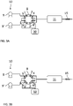
- FIG. 2A shows schematically a further step of the method, where the downstream pump 40 is used for backflushing the fluidic stream 11.
- the wash selection valve 70, the downstream valve 20 and the three-way valve 16 are switched such that the downstream pump 40 is connected via the fluidic stream wash port 71, the three-way valve 16, the downstream-pump-inlet port 21' and the fluidic-stream port 21 to the fluidic stream 11.
- the fluidic stream 12 is connected to the valve-to-detector conduit 30 via fluidic-stream port 22 and valve-to-detector conduit port 25, whereas the fluidic stream 13 is directed to waste 50 via fluidic-stream port 23, waste port 23' and three-way valve 18 respectively.
- the direction of flow 15 for the fluidic stream 11 is inverted in FIG. 2A .
- FIG. 2B shows schematically a further step of the method, where the downstream pump 40 is used for backflushing the fluidic stream 12.
- the wash selection valve 70, the downstream valve 20 and the three-way valve 17 are switched such that the downstream pump 40 is connected via the fluidic stream wash port 72, the three-way valve 17, the downstream-pump-inlet port 22' and the fluidic-stream port 22 to the fluidic stream 12.
- the fluidic stream 11 is connected to the valve-to-detector conduit 30 via fluidic-stream port 21 and valve-to-detector conduit port 25, whereas the fluidic stream 13 is directed to waste 50 via fluidic-stream port 23, waste port 23' and three-way valve 18 respectively.
- the direction of flow 15 for the fluidic stream 12 is inverted in FIG. 2B .
- FIG. 2C shows schematically a further step of the method, where the downstream pump 40 is used for backflushing the fluidic stream 13.
- the wash selection valve 70, the downstream valve 20 and the three-way valve 18 are switched such that the downstream pump 40 is connected via the fluidic stream wash port 73, the three-way valve 18, the downstream-pump-inlet port 23' and the fluidic-stream port 23 to the fluidic stream 13.
- the fluidic stream 11 is connected to the valve-to-detector conduit 30 via fluidic-stream port 21 and valve-to-detector conduit port 25, whereas the fluidic stream 12 is directed to waste 50 via fluidic-stream port 22, waste port 22' and three-way valve 17 respectively.
- the direction of flow 15 for the fluidic stream 13 is inverted in FIG. 2C .
- FIG. 3A shows schematically further aspects of the LC system 100 and method of FIGS. 1A-1E .
- the LC system 100 further comprises an upstream LC pump 10 for each fluidic stream 11 (only one fluidic stream shown in FIG. 3A for simplicity) and in particular a binary LC pump comprising two pump heads 9, 9' merging into the fluidic stream 11 via an upstream valve 8.
- the upstream valve 8 is embodied in this example as an 8-port/two-way valve comprising two upstream pump inlet ports 1,1' fluidically connected to the pump heads 9, 9' respectively, two upstream pump outlet ports 2, 2' leading to the fluidic stream 11, two upstream pump waste ports 3, 3' leading liquid pumped by the pump heads 9, 9' respectively to waste 50, and two backflush waste ports 4, 4'.
- the method of FIG. 3A comprises switching the upstream valve 8 such that the upstream pump inlet ports 1, 1' are connected to the upstream pump outlet ports 2, 2' respectively in order to direct liquid flow from the upstream LC pump 10 into the fluidic stream 1, via the upstream valve 8, in normal flow direction 15.
- FIG. 3B shows schematically the same LC system 100 of FIG. 3A and further aspects of the method of FIGS. 2A-2C .
- the method comprises switching the upstream valve 8 such that the upstream pump inlet ports 1, 1' are connected to the upstream pump waste ports 3, 3' respectively, thus leading liquid pumped by the pump heads 9, 9' to waste.
- the upstream pump outlet ports 2, 2' are connected to the backflush waste ports 4, 4' respectively in order to direct liquid flow from the downstream pump via the fluidic stream 11 in reversed flow direction 15 to waste 50.
Abstract
Description
- The present disclosure is related to an automated liquid chromatography system and method comprising liquid chromatographic column backflushing.
- Automated in-vitro diagnostic analyzers are prevalent in clinical laboratories and hospital environments. These devices have become more and more complex due to added functionalities and increased sample throughput. Consequently, errors and malfunctions can occur in a multitude of device components, increasing the potential for decreased productivity of the analyzer and/or less reliable measurement results. In particular, there is a growing interest for the implementation of mass spectrometry and, more specifically, of liquid chromatography (LC) coupled to mass spectrometry in the clinical laboratory for in-vitro diagnostics use, which brings an additional level of complexity and technical challenges when it comes to automation.
- The intense workload posed on some components of the system and particularly the LC system may require frequent maintenance procedures.
- In particular, HPLC columns, may undergo continuous deterioration of their performance as the number of sample injections increases, resulting e.g. in increasing background, shifting of retention times, shortened column lifetime, increased costs, and need for frequent maintenance, mostly due to particulate build-up at the column head.
- Backflushing an HPLC column can provide higher sample throughput, more uptime, less maintenance, lower costs, higher data quality, and longer lasting calibrations. This is typically done by manually disconnecting the column from the flow system and reconnecting the outlet side of the column to the flow inlet such as to reverse the flow direction through the column, whereas the flow out of the column is typically directed to waste in order not to contaminate the detector. This manual procedure may take 15-20 min or more for each column before the column is reconnected in the original orientation with the correct flow direction, followed by re-equilibration and quality control.
- This manual procedure can be laborious, time consuming, and require the intervention of external service personnel or of skilled laboratory personnel, during which time an analyzer or component thereof might not be available for use, besides generating additional costs and introducing a risk of errors and malfunctions and even of system damage.
- It is against the above background that the embodiments of the present disclosure provide certain unobvious advantages and advancements over the prior art. In particular, the inventors have recognized a need for improvements in LC systems and methods including column backflushing.
- Although the embodiments of the present disclosure are not limited to specific advantages or functionality, it is noted that the present disclosure provides an LC system and method, which enable, among other functions, automated HPLC column backflushing, thereby ensuring continued analytical performance of the system and extension of the HPLC column lifetime, without manual intervention and hence with increased user convenience. Other advantages are that system downtime is minimized, costs are reduced and risk of errors, malfunctions and system damage are eliminated.
- In particular, the liquid chromatographic (LC) system herein disclosed comprises at least one fluidic stream comprising at least one HPLC column, a downstream valve connected to the at least one fluidic stream and connectable to a detector via a valve-to-detector conduit, wherein the at least one fluidic stream is connectable to the valve-to-detector conduit via the downstream valve. The LC system further comprises a downstream pump fluidically connected to the downstream valve and connectable to the at least one fluidic stream via the downstream valve in order to backflush and thereby clean the at least one HPLC column.
- "Liquid chromatography or LC" is an analytical process that subjects samples injected by a sample injector to chromatographic separation through an LC column in order for example to separate analytes of interest from matrix components, e.g., remaining matrix components after sample preparation that may still interfere with a subsequent detection, e.g., a mass spectrometry detection, and/or in order to separate analytes of interest from each other in order to enable their individual detection. "High-performance liquid chromatography" or HPLC, "ultra-high-performance liquid chromatography" or UHPLC, "micro liquid chromatography" or µLC and "small-bore liquid chromatography" or small-bore LC are forms of liquid chromatography performed under pressure.
- A "liquid chromatographic system or LC system" is an analytical apparatus or module or a unit in an analytical apparatus for carrying out liquid chromatography. The LC system may be embodied as a single channel with one fluidic stream or as a multi-channel system with a plurality of fluidic streams, comprising one or a plurality of LC columns arranged in parallel and/or in series. The LC system may also comprise elements such as a sample injector, valves, liquid sources, fluidic connections and parts, e.g., for mixing liquids, degassing liquids, tempering liquids, and the like, one or more sensors, such as pressure sensors, temperature sensors and the like, and especially at least one LC pump. The list is not exhaustive.
- According to an embodiment, the detector can be a mass spectrometer connected to the valve-to-detector conduit via an ionization source. The detector may however be something other than a mass spectrometer, such as, i.e., an optical detector, e.g., a UV or fluorescence detector, an impedance detector, a conductivity detector and the like.
- According to an embodiment, the LC system can be configured as an analytical module designed to prepare a sample for mass spectrometry and/or to transfer a prepared sample to a mass spectrometer, in particular for separating analytes of interest before detection by a mass spectrometer. In particular, typically, during an LC run, the mass spectrometer may be set to scan a specific mass range. LC/MS data can be represented by adding up the ion current in the individual mass scans and plotting that "totaled" ion current as an intensity point against time. The resulting plot looks like an HPLC UV trace with analyte peaks.
- A "fluidic stream" is a fluidic path through which liquids can flow and in particular through which a sample from a sample injection point can be transferred to a detector, e.g., to a mass spectrometer or other detector, and through which the sample may undergo a chromatographic process. The fluidic connection through different parts of the fluidic stream may be discontinuous. This is because the fluidic stream may comprise elements such as switching valves that may establish alternative connections and regulate fluidic flow between different parts of the fluidic stream at different times. The fluidic stream may comprise at least one LC column. The at least one LC column may be exchangeable. In particular, the LC system may comprise more LC columns than fluidic streams, where a plurality of LC columns may be selectable, e.g., interchangeably coupled to the same fluidic stream. Capillary tubing may be also used to bypass LC columns. A fluidic stream may comprise a plurality of substreams.
- In particular, the LC system in accordance with one or more embodiments of this disclosure may comprise a plurality of fluidic streams connected to a downstream valve for directing flow from one fluidic stream at a time to a detector.
- An "LC column" may refer to any of a column, a cartridge, a capillary and the like for performing separations of a chromatographic nature. Columns are typically packed or loaded with a stationary phase, through which a mobile phase is pumped in order to trap and/or separate and elute and/or transfer analytes of interest under selected conditions, e.g., according to their polarity or log P value, size or affinity, as generally known. This stationary phase can be particulate or beadlike or a porous monolith. However, the term "column" may also refer to capillaries or channels that are not packed or loaded with a stationary phase, but rely on the surface area of the inner capillary wall or geometrical structures to effect separations. An example is provided by pillar array chromatography, where separation beds are formed by etching away interstitial volumes out of a solid silicon wafer, leaving an array of pillars. The resulting channels can be folded onto a small footprint by concatenating bed segments with optimized flow distributors that limit peak dispersion. This creates a stationary phase support structure that is organized in a reproducible, ordered pattern.
- The LC column may be exchangeable and/or operate in parallel or in sequence to one or more other LC columns. An LC column may be for example a rapid trap and elute LC column or "trap-column" for short, a HPLC column or a UHPLC column, and may be of any size, including micro-LC columns and small-bore LC columns, or pillar array LC columns. In the case of trap-columns, a stationary phase can be selected, which retains analytes of interest, whereas any salts, buffer, detergents and other matrix components are unretained and washed away. This process is typically followed by elution of the analytes, e.g., in back flush mode, with a different mobile phase or a solvent gradient. Depending on the analytes, separation of some analytes can be expected in some cases. On the other hand, in case of analytes having identical masses (isobaric) and/or overlapping daughter ion spectra in multiple reaction monitoring (MRM), when it comes to mass spectrometry, a more extensive chromatographic separation could be typical. In that case, separation in a HPLC or UHPLC column may be advantageous.
- For the purpose of this disclosure, the at least one fluidic stream comprises at least one HPLC column (where the term "HPLC" encompasses for simplicity also UHPLC or other high-performance column like µ-LC and small-bore columns), distinguished from rapid trap and elute LC columns, and which is typically not subject to backflushing during an analytical run and for which it is typically required to manually intervene by disconnecting the column, reversing the flow direction by reconnecting the column in reversed orientation, and directing the flow to waste and not to the detector in order to backflush it for the only purpose to clean the column.
- A "liquid chromatography pump or LC pump" is a high-pressure pump that may vary in pressure capacity but that can yield a consistent and reproducible volumetric flow rate though an LC channel. Pressure in HPLC may typically reach as high as 60 MPa or about 600 atmospheres, whereas UHPLC and µ-LC systems have been developed to work at even higher pressures, e.g., up to 140 MPa or about 1400 atmospheres, and therefore are able to use much smaller particle sizes in the LC columns (<2 µm). LC pumps may be configured as binary pumps or even quaternary pumps, e.g., in case of conditions requiring the use of elution gradients by gradually varying the ratio between up to four elution solvents.
- According to one embodiment, the LC pump can yield a pressure of 60 MPa to 140 MPa, typically 75 MPa to 100 MPa, and more typically 80 MPa.
- According to one embodiment, the LC pump can be configured to operate with a flow rate between 1 µl/min and 500 µl/min or more, typically up to 1500 µl/min, and more typically operate at flow rates between 100 µl/min to 300 µl/min, and an accuracy of, e.g., about ± 5% or less.
- The LC pump may comprise more than one pump head. For example, binary pumps comprise two pump heads and each pump head typically comprises a primary pump head and a secondary pump head cooperating with each other for pumping liquid while maintaining the liquid pressure inside the pump head about constant. In particular, each of the primary pump head and of the secondary pump head is typically a syringe-like pump comprising a syringe-like cylinder body having an inner wall surface and a plunger translatable through the cylinder body leaving an interspace between the inner wall surface and the plunger when the plunger is translated through the cylinder body.
- The term "liquid" in relation to a fluidic stream refers to liquids commonly used in liquid chromatography, e.g., as solvents or mixtures of solvents used, e.g., as mobile phases or eluents (elution solvents), and as known in the art.
- A "downstream pump" is an auxiliary pump distinguished at least in function from the LC pump, possibly a multi-function pump, including at least the function of backflushing the at least one HPLC column in order to clean it. Another possible function is that to facilitate and to speed up liquid exchange within the valve-to-detector conduit. In general, the downstream pump is a lower-pressure and higher-volume (higher-flow-rate) pump compared to the LC pump, and is fluidically connected to the downstream valve. Typically, the downstream pump according to the present disclosure is also a lower-precision pump and hence is also simpler in construction and less expensive in comparison to an LC pump. According to an embodiment of the present disclosure the downstream pump is a positive-pressure pump. Any pump suitable to generate a positive-pressure in order to actively pump a wash liquid or mobile phase from a liquid source through the at least one HPLC column in backflush and/or through the valve-to-detector conduit, via the stream-selection valve, may be used, like for example membrane/diaphragm pumps, single-plunger high-speed pumps, syringe-piston pumps, gear pumps and the like. According to an embodiment, positive pressure and active pumping may be achieved by applying pneumatic pressure, e.g., by pressurized gas, e.g., by a nitrogen supply, into a sealed liquid container connected to the upstream inlet valve.
- According to an embodiment, the downstream pump is configured to pump a wash liquid through the HPLC column and/or through the valve-to-detector conduit at a flow rate higher than that of the fluidic streams, e.g., several times higher, for example, 5 times, 10 times, 20 times or higher. For example, in case of µ-LC with typical flow rates around 1 µL/min, a wash pump flow rate of 5 µL/min may be already beneficial. In case of flow rates of the fluidic streams around 100 µL/min, effective flow rates for the downstream pump can be around 500 - 1000 µL/min or higher. According to some embodiments, flow rates for the downstream pump up to 5000 µL/min are possible. The flow rate may be variable depending on whether the wash liquid is directed to an HPLC column or to the valve-to-detector conduit.
- A "wash liquid" can be a liquid suitable to wash out, eventually to dissolve, particulate substances, adsorbed matrix components and the like, build-up on the HPLC column head during multiple sample injections cycles. A wash liquid can be a liquid suitable to wash out, eventually to dissolve, eventual traces of samples from the valve-to-detector conduit while still being compatible with the detector used, e.g., with a mass spectrometer. A wash liquid may be the same as or similar to an elution solvent used for chromatography, which depending on the type of column, or type of samples and analytes passed through the column may be different. For example, for analytes for which typically reversed-phase chromatography is used, suitable solvents may be organic solvents like methanol, acetonitrile, tetrahydrofuran, and/or isopropylic alcohol. These solvents may be also mixed with each other and/or with water. Acidic or basic additives may be added to adjust the pH. Typical additives can include formic acid, ammonium formate, ammonium acetate, etc. For example, for analytes for which typically normal-phase chromatography is used, suitable solvents may include solvents like hexane, heptane mixed with polar organic solvents such as ethyl acetate, chloroform or 2-propanol. The wash liquid may be the same or different for backflushing an HPLC column and for washing the valve-to-detector conduit respectively, depending on the HPLC column.
- The term "valve" refers to a flow-regulating device to control, redirect, restrict or stop flow and, in particular, to an LC switching valve, that is a multi-port valve that controls flow between elements connected to the ports. This is typically achieved by moving one or more valve conduits to switch communication between different elements. Elements may be fluidically connected to the ports via further conduits, like pipes, tubes, capillaries, microfluidic channels and the like, and by fittings like screws/nuts and ferrules, or alternative liquid-tight seals, e.g., maintained in place by a clamp mechanism. An LC switching valve is normally capable of allowing liquid pressures in the order of magnitude used for HPLC or higher.
- In particular, the "downstream valve" is an LC switching valve located downstream with respect to the at least one HPLC column in the normal direction of flow from the HPLC column to the detector. The downstream valve may comprise a port for each fluidic stream, a port for the valve-to-detector conduit, one or more downstream-pump ports and one or more waste ports.
- According to an embodiment, the downstream valve has an inner valve conduit(s) with an inner diameter of less than 0.6 mm, typically between about 0.5 mm and 0.2 mm, more typically about 0.4 mm, and even more typically about 0.25 mm. The inner valve conduit can have however any other diameter in typically used ranges.
- According to an embodiment, the downstream valve has a typical switching time of about 500 ms or less. The switching time can be however also longer than 500 ms.
- According to an embodiment, the LC system comprises a plurality of fluidic streams alternately connectable to the valve-to-detector conduit via the downstream valve.
- According to an embodiment, the downstream pump is also connectable to the valve-to-detector conduit via the downstream valve in order to wash the valve-to-detector conduit.
- According to an embodiment, the downstream pump is configured to connect to the valve-to-detector conduit between two consecutive fluidic streams in order to wash liquid from a previous fluidic stream out of the valve-to-detector conduit before liquid from a subsequent fluidic stream enters the valve-to-detector conduit.
- According to an embodiment, the downstream pump is connected to the downstream valve via a wash selection valve, where the wash selection valve is configured to alternately connect to any one of the at least one fluidic stream and to the valve-to-detector conduit via the downstream valve.
- A "wash selection valve" is an LC switching valve located between the downstream pump and the downstream valve, and comprising a downstream-pump inlet port, one wash outlet port for each fluidic stream to be backflushed, where the fluidic connection between the outlet port and the respective fluidic stream is via the downstream valve, and eventually one wash outlet port connectable to the valve-to-detector conduit via the downstream valve.
- According to an embodiment, the wash selection valve is connectable to the at least one fluidic stream via a respective three-way valve fluidically connected to the downstream valve, the three-way valve comprising a wash-selection-valve inlet port, a downstream-valve outlet port and a waste outlet port.
- The LC system may comprise a controller configured to automatically backflush the at least one HPLC column at regular intervals and/or upon detection of a pressure rise above a predetermined threshold in the at least one fluidic stream and/or upon detection of performance reduction below a predetermined threshold, by e.g. monitoring data like increase of signal background, shifts in analyte retention times, peak shape alteration and the like during use of the at least one HPLC column.
- According to an embodiment, the controller is further configured to manage a fluidic-stream-to-detector connection time, that is the connection time between the at least one fluidic stream and the valve-to-detector conduit, a downstream-pump-to-detector connection time, that is the connection time between the downstream pump and the valve-to-detector conduit, and a downstream-pump-to-fluidic-stream connection time, that is the connection time between the at least one fluidic stream and the downstream pump, by controlling switching of any one or more of the downstream valve, the wash selection valve, the three-way valve(s).
- According to an embodiment, the fluidic-stream-to-detector connection time is fixed and is the same for each fluidic stream. In addition, the downstream-pump-to-detector connection time is fixed and is a fraction of the fluidic-stream-to-detector connection time, thereby resulting at least temporarily in a continuous switching at a regular pace. It may in particular be beneficial if the downstream-pump-to-detector connection time is 20% or less, typically 10% or less, or more typically 5% or less of the fluidic-stream-to-detector connection time and that the conditions of the downstream pump in terms of, e.g., flow rate and/or washing liquid, are so adapted that the downstream-pump-to-detector connection time is minimized. In absolute terms the downstream-pump-to-detector connection time may be as short as a few seconds, typically 5s or less, more typically 3s or less.
- As used herein, the term "controller" can mean a processing unit, such as a microprocessor, a microcontroller, a reduced instruction circuit (RISC), an application specific integrated circuit (ASIC), a logic circuit, and any other circuit or processor capable of executing the functions/methods described herein.
- The controller may be integrated into the analytical system or be a separate logic entity in communication with the analytical system via a direct connection, wired or wirelessly, or indirectly over a communications network, wired or wirelessly, such as a wide area network, e.g., the Internet or a Health Care Provider's local area network or intranet, via a network interface device. In some embodiments, the processor might be integral with a data management unit, e.g., implemented on a computing device such as a desktop computer, a laptop, a smartphone, a tablet, PDA, etc. It may include a server computer and/or be distributed/shared across/between a plurality of analytical systems. Moreover, the analytical system can include remote devices, servers and cloud-based elements that communicate via wires or wirelessly (e.g., infrared, cellular, Bluetooth®) with the controller, or a remote PC/server or a cloud-based system. The controller may be also configurable to control the analytical system in a way that workflow(s) and workflow step(s) are conducted by the analytical system. In particular, the processor may communicate and/or cooperate with a scheduler and/or a data manager in order to take into account incoming test orders and/or received test orders, and a number of scheduled process operations associated with the execution of the test orders, in combination with managing the various connection times and valves switching.
- In accordance with another embodiment of the instant disclosure, an automated LC method is herein also disclosed, the method comprising comprising fluidically connecting at least one fluidic stream comprising at least one HPLC column to a downstream valve in order to connect the at least one fluidic stream to a detector via a valve-to-detector conduit, the method further comprising fluidically connecting a downstream pump to the at least one fluidic stream (via the downstream valve in order to backflush and thereby clean the at least one HPLC column.
- According to an embodiment, the LC method comprises alternately connecting a plurality of fluidic streams to the valve-to-detector conduit via the downstream valve.
- According to an embodiment, the LC method comprises connecting the downstream pump to the valve-to-detector conduit via the downstream valve in order to wash the valve-to-detector conduit.
- According to an embodiment, the LC method comprises connecting the downstream pump to the valve-to-detector conduit between two consecutive fluidic streams in order to wash liquid from a previous fluidic stream out of the valve-to-detector conduit before liquid from a subsequent fluidic stream enters the valve-to-detector conduit.
- According to an embodiment, the LC method comprises connecting the downstream pump to the downstream valve via a wash selection valve, and alternately connecting the wash selection valve to any one of the at least one fluidic stream and to the valve-to-detector conduit via the downstream valve.
- According to an embodiment, the LC method comprises connecting the wash selection valve to the at least one fluidic stream via a respective three-way valve fluidically connected to the downstream valve, the three-way valve comprising a wash-selection-valve inlet port, a downstream-valve outlet port and a waste outlet port.
- According to an embodiment, the LC method comprises automatically backflushing the at least one HPLC column at regular intervals and/or upon detection of a pressure rise above a predetermined threshold in the at least one fluidic stream and/or upon detection of performance reduction below a predetermined threshold, by e.g. monitoring data like increase of signal background, shifts in analyte retention times, peak shape alteration and the like during use of the at least one HPLC column.
- According to an embodiment, the LC method comprises automatically managing by a controller a fluidic-stream-to-detector connection time, that is the connection time between the at least one fluidic stream and the valve-to-detector conduit, a downstream-pump-to-detector connection time, that is the connection time between the downstream pump and the valve-to-detector conduit, and a downstream-pump-to-fluidic-stream connection time, that is the connection time between the at least one fluidic stream and the downstream pump, by controlling switching of any one or more of the downstream valve, wash selection valve, three-way valve(s).
- According to an embodiment, the method can further comprise automatically managing a fluidic-stream connection time, that is the connection time between each fluidic stream and the valve-to-detector conduit, and a wash-pump connection time, that is the connection time between the wash pump and the valve-to-detector conduit, by controlling switching of the stream-selection valve.
- According to another embodiment, the fluidic-stream connection time can be fixed and is the same for each fluidic stream, and wherein the wash-pump connection time is fixed and is a fraction of the fluidic-stream connection time, thereby resulting at least temporarily in a continuous switching at a regular pace.
- Other and further objects, features and advantages will appear from the following description of exemplary embodiments in combination with the drawings and the accompanying claims. It is noted that the scope of the claims is defined by the recitations therein and not by the specific discussion of features and advantages set forth in the present description.
- The following detailed description of the embodiments of the present disclosure can be best understood when read in conjunction with the following drawings, where like structure is indicated with like reference numerals and in which:
-
FIG. 1A shows schematically an LC system comprising a downstream pump connected to a downstream valve and a first step of an LC method comprising using the downstream pump. -
FIG. 1B shows schematically the same LC system ofFIG. 1A and a second step of the same method. -
FIG. 1C shows schematically the same LC system ofFIG. 1A and a third step of the same method. - FIG. ID shows schematically the same LC system of
FIG. 1A and a fourth step of the same method, which is identical to that ofFIG. 1B . -
FIG. 1E shows schematically the same LC system ofFIG. 1A and a fifth step of the same method. - FIG. IF shows schematically the same LC system of
FIG. 1A and a sixth step of the same method, which is identical to that ofFIG. 1B and FIG. ID. -
FIG. 2A shows schematically the same LC system ofFIGS. 1A-1F and a first step of a method of using the downstream pump for backflushing the fluidic streams. -
FIG. 2B shows schematically the same LC system ofFIG. 2A and a second step of the same method. -
FIG. 2C shows schematically the same LC system ofFIG. 2A and a third step of the same method. -
FIG. 3A shows schematically further aspects of the LC system and method ofFIGS. 1A-1E . -
FIG. 3B shows schematically the same LC system ofFIG. 3A and further aspects of the method ofFIGS. 2A-2C . - Skilled artisans appreciate that elements in the figures are illustrated for simplicity and clarity and have not necessarily been drawn to scale. For example, the dimensions of some of the elements in the figures may be exaggerated relative to other elements to help improve understanding of the embodiments of the present disclosure.
-
FIGS. 1A-1F andFIGS. 2A-2C taken together show a schematic example of liquid chromatographic (LC)system 100 comprising a plurality offluidic streams common detector 60 via adownstream valve 20 connected to thedetector 60 via a valve-to-detector conduit 30, each of the fluidic streams 11, 12, 13 comprising at least one HPLC column. TheLC system 100 further comprises adownstream pump 40 fluidically connected to thedownstream valve 20 and configured to connect to the valve-to-detector conduit 30 between two consecutive fluidic streams 11,12; 12,13; 13,11 in order to wash liquid from a previous fluidic stream out of the valve-to-detector conduit 30 before liquid from a subsequent fluidic stream enters the valve-to-detector conduit 30. - In particular, the
downstream valve 20 comprises in this case a fluidic-stream port fluidic stream fluidic stream waste 50, where the waste ports 21', 22', 23' can function also as downstream-pump-inlet ports 21', 22', 23' connectable to the fluidic streams 11, 12, 13, via the fluidic-stream port downstream valve 20 comprises in addition a valve-to-detector conduit port 25, connected to the valve-to-detector conduit 30 and alternately connectable to each of thefluidic stream stream ports downstream valve 20 further comprises an additional downstream-pump-inlet port 24 also connectable to the valve-to-detector conduit 30 via the valve-to-detector conduit port 25 and a downstream-pump-waste port 24' leading to thewaste 50 when connected to the downstream-pump-inlet port 24. It is clear that this is only an example and the number of ports and connections, as well as the sequence of switching between fluidic streams, may be adapted according to the need and according to the number of fluidic streams. - The
downstream pump 40 is connected in this example to four wash liquid containers containingrespective wash liquid washing pump 40 may be configured to pump a wash liquid through the valve-to-detector conduit 30 and/or through thefluidic stream flow rate 45 higher than aflow rate 15 of the fluidic streams 11, 12, 13 by respective upstream LC pumps (not shown inFIGS. 1A-1F ,FIGS. 2A-2C ). - The
downstream pump 40 is connected to thedownstream valve 20 via awash selection valve 70. Thewash selection valve 70 is configured to alternately connect thedownstream pump 40 to any one of the fluidic streams 11, 12, 13 and to the valve-to-detector conduit 30 via thedownstream valve 20. In particular, thewash selection valve 70 is connectable to the fluidic streams 11, 12, 13 via respective fluidic stream washports way valves downstream valve 20 via the downstream-pump-inlet ports 21', 22', 23' respectively, the three-way valves waste 50. Thewash selection valve 70 further comprises a valve-to-detector-conduit wash port 74 connected to thedownstream valve 20 via the downstream-pump-inlet port 24. - The
LC system 100 further comprises acontroller 90 configured to automatically backflush the HPLC columns of the respective fluidic streams 11, 12, 13 at regular intervals and/or upon detection of a pressure rise above a predetermined threshold in the at least one fluidic stream and/or upon detection of performance reduction of the HPLC columns below a predetermined threshold. - The
controller 90 is further configured to manage a fluidic-stream-to-detector connection time, that is the connection time between the afluidic stream detector conduit 30, a downstream-pump-to-detector connection time, that is the connection time between thedownstream pump 40 and the valve-to-detector conduit 30, and a downstream-pump-to-fluidic-stream connection time, that is the connection time between afluidic stream downstream pump 40, by controlling switching of thedownstream valve 20, thewash selection valve 70 and the three-way valves - With continued reference to
FIGS. 1A-1F ,FIGS. 2A-2C taken together, an LC method is also schematically shown, the method comprising fluidically connecting at least onefluidic stream downstream valve 20 in order to connect the at least onefluidic stream detector 60 via a valve-to-detector conduit 30, the method further comprising fluidically connecting adownstream pump 40 to the at least onefluidic stream downstream valve 20 in order to backflush and thereby clean the at least one HPLC column. - The LC method further comprises alternately connecting a plurality of
fluidic streams detector conduit 30 via thedownstream valve 20. - The LC method further comprises connecting the
downstream pump 40 to the valve-to-detector conduit 30 via thedownstream valve 20 in order to wash the valve-to-detector conduit 30. - The LC method further comprises connecting the
downstream pump 40 to the valve-to-detector conduit 30 between two consecutive fluidic streams 11,12; 12,13; 13,11 in order to wash liquid from a previous fluidic stream out of the valve-to-detector conduit 30 before liquid from a subsequent fluidic stream enters the valve-to-detector conduit 30. - The LC method further comprises connecting the
downstream pump 40 to thedownstream valve 20 via thewash selection valve 70 and alternately connecting thewash selection valve 70 to any one of the at least onefluidic stream detector conduit 30 via thedownstream valve 20. - Particularly, the LC method comprises connecting the
wash selection valve 70 to the at least onefluidic stream way valve downstream valve 20, the three-way valve - According to an embodiment, the LC method further comprises automatically backflushing the at least one HPLC column at regular intervals and/or upon detection of a pressure rise above a predetermined threshold in the at least one fluidic stream and/or upon detection of performance reduction of the at least one HPLC column below a predetermined threshold.
- The LC method may further comprise automatically managing by the controller 90 a fluidic-stream-to-detector connection time, that is the connection time between the at least one
fluidic stream detector conduit 30, a downstream-pump-to-detector connection time, that is the connection time between thedownstream pump 40 and the valve-to-detector conduit 30, and a downstream-pump-to-fluidic-stream connection time, that is the connection time between the at least onefluidic stream downstream pump 40, by controlling switching of any one or more of thedownstream valve 20, thewash selection valve 70, the three-way valve(s) 16, 17, 18. - In particular,
FIG. 1A shows a first step of the method in which the downstream-valve 20 is switched such as thefluidic stream 11 is connected and directed to the valve-to-detector conduit 30, whereas the other fluidic streams 12, 13 are directed to waste 50 via waste ports 22', 23', and three-way valves 17, 18 respectively. Wash liquid from thedownstream pump 40 is also directed to waste 50 via thedownstream valve 20, thewash selection valve 70 being connected to the downstream-pump-inlet port 24 via the valve-to-detector-conduit wash port 74 and the downstream-pump-inlet port 24 being connected to the downstream-pump-waste port 24'. -
FIG. 1B shows a second step of the method in which thedownstream valve 20 is switched such as thedownstream pump 40 is connected to the valve-to-detector conduit 30, by having the downstream-pump-inlet port 24 directly connected to the valve-to-detector conduit port 25 whereas allfluidic streams way valves -
FIG. 1C shows a third step of the method in which thedownstream valve 20 is switched such as the fluidic stream 12 is connected to the valve-to-detector conduit 30, whereas the other fluidic streams 11, 13 are directed to waste 50 via waste ports 21', 23' and three-way valves downstream pump 40 is also directed to waste 50 via the downstream-pump-waste port 24' of thedownstream valve 20 as inFIG. 1A . - The fourth step of the method as shown in FIG. ID is identical to the second step of
FIG. 1B . -
FIG. 1E shows a fifth step of the method in which thedownstream valve 20 is switched such as thefluidic stream 13 is connected to the valve-to-detector conduit 30, whereas the other fluidic streams 11, 12 are directed to waste 50 via waste ports 21', 22' and three-way valves 16, 17 respectively. Wash liquid from thedownstream pump 40 is also directed to waste 50 via the downstream-pump-waste port 24' of thedownstream valve 20 as inFIG. 1A andFIG. 1C . - The sixth step of the method shown in FIG. IF is identical to the second step of
FIG. 1B and fourth step ofFIG. 1B , before starting over again with the first step ofFIG. 1A . -
FIG. 2A shows schematically a further step of the method, where thedownstream pump 40 is used for backflushing thefluidic stream 11. In particular, thewash selection valve 70, thedownstream valve 20 and the three-way valve 16 are switched such that thedownstream pump 40 is connected via the fluidic stream washport 71, the three-way valve 16, the downstream-pump-inlet port 21' and the fluidic-stream port 21 to thefluidic stream 11. At the same time, the fluidic stream 12 is connected to the valve-to-detector conduit 30 via fluidic-stream port 22 and valve-to-detector conduit port 25, whereas thefluidic stream 13 is directed to waste 50 via fluidic-stream port 23, waste port 23' and three-way valve 18 respectively. It is to be noticed that the direction offlow 15 for thefluidic stream 11 is inverted inFIG. 2A . -
FIG. 2B shows schematically a further step of the method, where thedownstream pump 40 is used for backflushing the fluidic stream 12. In particular, thewash selection valve 70, thedownstream valve 20 and the three-way valve 17 are switched such that thedownstream pump 40 is connected via the fluidic stream washport 72, the three-way valve 17, the downstream-pump-inlet port 22' and the fluidic-stream port 22 to the fluidic stream 12. At the same time, thefluidic stream 11 is connected to the valve-to-detector conduit 30 via fluidic-stream port 21 and valve-to-detector conduit port 25, whereas thefluidic stream 13 is directed to waste 50 via fluidic-stream port 23, waste port 23' and three-way valve 18 respectively. It is to be noticed that the direction offlow 15 for the fluidic stream 12 is inverted inFIG. 2B . -
FIG. 2C shows schematically a further step of the method, where thedownstream pump 40 is used for backflushing thefluidic stream 13. In particular, thewash selection valve 70, thedownstream valve 20 and the three-way valve 18 are switched such that thedownstream pump 40 is connected via the fluidic stream washport 73, the three-way valve 18, the downstream-pump-inlet port 23' and the fluidic-stream port 23 to thefluidic stream 13. At the same time, thefluidic stream 11 is connected to the valve-to-detector conduit 30 via fluidic-stream port 21 and valve-to-detector conduit port 25, whereas the fluidic stream 12 is directed to waste 50 via fluidic-stream port 22, waste port 22' and three-way valve 17 respectively. It is to be noticed that the direction offlow 15 for thefluidic stream 13 is inverted inFIG. 2C . -
FIG. 3A shows schematically further aspects of theLC system 100 and method ofFIGS. 1A-1E . In particular, theLC system 100 further comprises anupstream LC pump 10 for each fluidic stream 11 (only one fluidic stream shown inFIG. 3A for simplicity) and in particular a binary LC pump comprising twopump heads 9, 9' merging into thefluidic stream 11 via anupstream valve 8. Theupstream valve 8 is embodied in this example as an 8-port/two-way valve comprising two upstreampump inlet ports 1,1' fluidically connected to the pump heads 9, 9' respectively, two upstreampump outlet ports 2, 2' leading to thefluidic stream 11, two upstreampump waste ports 3, 3' leading liquid pumped by the pump heads 9, 9' respectively to waste 50, and twobackflush waste ports 4, 4'. The method ofFIG. 3A comprises switching theupstream valve 8 such that the upstreampump inlet ports 1, 1' are connected to the upstreampump outlet ports 2, 2' respectively in order to direct liquid flow from theupstream LC pump 10 into thefluidic stream 1, via theupstream valve 8, innormal flow direction 15. -
FIG. 3B shows schematically thesame LC system 100 ofFIG. 3A and further aspects of the method ofFIGS. 2A-2C . In particular the method comprises switching theupstream valve 8 such that the upstreampump inlet ports 1, 1' are connected to the upstreampump waste ports 3, 3' respectively, thus leading liquid pumped by the pump heads 9, 9' to waste. Also, the upstreampump outlet ports 2, 2' are connected to thebackflush waste ports 4, 4' respectively in order to direct liquid flow from the downstream pump via thefluidic stream 11 in reversedflow direction 15 to waste 50. - In the preceding specification, numerous specific details are set forth in order to provide a thorough understanding of the present disclosure. It will be apparent, however, to one having ordinary skill in the art, that the specific details need not be employed to practice the present teaching. In other instances, well-known materials or methods have not been described in detail in order to avoid obscuring the present disclosure.
- Particularly, modifications and variations of the disclosed embodiments are certainly possible in light of the above description. It is therefore to be understood, that within the scope of the appended claims, the invention may be practiced otherwise than as specifically devised in the above examples.
- Reference throughout the preceding specification to "one embodiment", "an embodiment", "one example" or "an example", "one aspect" or "an aspect" means that a particular feature, structure or characteristic described in connection with the embodiment or example or aspect is included in at least one embodiment. Thus, appearances of the phrases "in one embodiment", "in an embodiment", "one example" or "an example", "one aspect" or "an aspect" in various places throughout this specification are not necessarily all referring to the same embodiment or example or aspect.
- Furthermore, the particular features, structures, or characteristics may be combined in any suitable combinations and / or sub-combinations in one or more embodiments or examples or aspects.
Claims (16)
- A liquid chromatographic (LC) system (100) comprising- at least one fluidic stream (11, 12, 13) comprising at least one HPLC column,- a downstream valve (20) connected to the at least one fluidic stream (11, 12, 13) and connectable to a detector (60) via a valve-to-detector conduit (30), wherein the at least one fluidic stream (11, 12, 13) is connectable to the valve-to-detector conduit (30) via the downstream valve (20),characterized in that
the LC system (100) further comprises a downstream pump (40) fluidically connected to the downstream valve (20) and connectable to the at least one fluidic stream (11, 12, 13) via the downstream valve (20) in order to backflush and thereby clean the at least one HPLC column. - The LC system (100) according to claim 2 wherein the LC system (100) comprises a plurality of fluidic streams (11, 12, 13) alternately connectable to the valve-to-detector conduit (30) via the downstream valve (20).
- The LC system (100) according to claim 1 or 2 wherein the downstream pump (40) is also connectable to the valve-to-detector conduit (30) via the downstream valve (20) in order to wash the valve-to-detector conduit (30).
- The LC system (100) according to claim 3 wherein the downstream pump (40) is configured to connect to the valve-to-detector conduit (30) between two consecutive fluidic streams in order to wash liquid from a previous fluidic stream out of the valve-to-detector conduit (30) before liquid from a subsequent fluidic stream enters the valve-to-detector conduit (30).
- The LC system (100) according to any of the preceding claims wherein the downstream pump (40) is connected to the downstream valve (20) via a wash selection valve (70), and wherein the wash selection valve (70) is configured to alternately connect to any one of the at least one fluidic stream (11, 12, 13) and to the valve-to-detector conduit (30) via the downstream valve (20).
- The LC system (100) according to claim 5 wherein the wash selection valve (70) is connectable to the at least one fluidic stream (11, 12, 13) via a respective three-way valve (16, 17, 18) fluidically connected to the downstream valve (20), the three-way valve (16, 17, 18) comprising a wash-selection-valve inlet port, a downstream-valve outlet port and a waste outlet port.
- The LC system (100) according to any of the preceding claims comprising a controller (90) configured to automatically backflush the at least one HPLC column at regular intervals and/or upon detection of a pressure rise above a predetermined threshold in the at least one fluidic stream and/or upon detection of performance reduction of the at least one HPLC column below a predetermined threshold.
- The LC system (100) according to claim 7 wherein the controller (90) is further configured to manage a fluidic-stream-to-detector connection time, that is the connection time between the at least one fluidic stream (11, 12, 13) and the valve-to-detector conduit (30), a downstream-pump-to-detector connection time, that is the connection time between the downstream pump (40) and the valve-to-detector conduit (30), and a downstream-pump-to-fluidic-stream connection time, that is the connection time between the at least one fluidic stream (11, 12, 13) and the downstream pump (40), by controlling switching of any one or more of the downstream valve (20), the wash selection valve (70), the three-way valve(s) (16, 17, 18).
- An automated LC method comprising fluidically connecting at least one fluidic stream (11, 12, 13) comprising at least one HPLC column to a downstream valve (20) in order to connect the at least one fluidic stream (11, 12, 13) to a detector (60) via a valve-to-detector conduit (30), the method further comprising fluidically connecting a downstream pump (40) to the at least one fluidic stream (11, 12, 13) via the downstream valve (20) in order to backflush and thereby clean the at least one HPLC column.
- The LC method of claim 9 comprising alternately connecting a plurality of fluidic streams (11, 12, 13) to the valve-to-detector conduit (30) via the downstream valve (20).
- The LC method of claim 9 or 10 comprising connecting the downstream pump (40) to the valve-to-detector conduit (30) via the downstream valve (20) in order to wash the valve-to-detector conduit (30).
- The LC method according to claim 11 comprising connecting the downstream pump (40) to the valve-to-detector conduit (30) between two consecutive fluidic streams in order to wash liquid from a previous fluidic stream out of the valve-to-detector conduit (30) before liquid from a subsequent fluidic stream enters the valve-to-detector conduit (30).
- The LC method according to any of the claims 9 to 12 comprising connecting the downstream pump (40) to the downstream valve (20) via a wash selection valve (70), and alternately connecting the wash selection valve (70) to any one of the at least one fluidic stream (11, 12, 13) and to the valve-to-detector conduit (30) via the downstream valve (20).
- The LC method according to claim 13 comprising connecting the wash selection valve (70) to the at least one fluidic stream (11, 12, 13) via a respective three-way valve (16, 17, 18) fluidically connected to the downstream valve (20), the three-way valve (16, 17, 18) comprising a wash-selection-valve inlet port, a downstream-valve outlet port and a waste outlet port.
- The LC method according to any of the claims 9 to 14 comprising automatically backflushing the at least one HPLC column at regular intervals and/or upon detection of a pressure rise above a predetermined threshold in the at least one fluidic stream (11, 12, 13) and/or upon detection of performance reduction of the at least one HPLC column below a predetermined threshold.
- The LC method according to any of the claims 9 to 15 comprising automatically managing by a controller (90) a fluidic-stream-to-detector connection time, that is the connection time between the at least one fluidic stream (11, 12, 13) and the valve-to-detector conduit (30), a downstream-pump-to-detector connection time, that is the connection time between the downstream pump (40) and the valve-to-detector conduit (30), and a downstream-pump-to-fluidic-stream connection time, that is the connection time between the at least one fluidic stream (11, 12, 13) and the downstream pump (40), by controlling switching of any one or more of the downstream valve (20), the wash selection valve (70), the three-way valve(s) (16, 17, 18).
Priority Applications (4)
| Application Number | Priority Date | Filing Date | Title |
|---|---|---|---|
| EP21171685.7A EP4083620A1 (en) | 2021-04-30 | 2021-04-30 | Lc system and method with column backflushing |
| US17/659,772 US20220349863A1 (en) | 2021-04-30 | 2022-04-19 | Lc system and method with column backflushing |
| CN202210450464.7A CN115267036A (en) | 2021-04-30 | 2022-04-26 | LC system and method using column back-flushing |
| JP2022074810A JP7398508B2 (en) | 2021-04-30 | 2022-04-28 | LC system and method with column backflushing |
Applications Claiming Priority (1)
| Application Number | Priority Date | Filing Date | Title |
|---|---|---|---|
| EP21171685.7A EP4083620A1 (en) | 2021-04-30 | 2021-04-30 | Lc system and method with column backflushing |
Publications (1)
| Publication Number | Publication Date |
|---|---|
| EP4083620A1 true EP4083620A1 (en) | 2022-11-02 |
Family
ID=75746543
Family Applications (1)
| Application Number | Title | Priority Date | Filing Date |
|---|---|---|---|
| EP21171685.7A Pending EP4083620A1 (en) | 2021-04-30 | 2021-04-30 | Lc system and method with column backflushing |
Country Status (4)
| Country | Link |
|---|---|
| US (1) | US20220349863A1 (en) |
| EP (1) | EP4083620A1 (en) |
| JP (1) | JP7398508B2 (en) |
| CN (1) | CN115267036A (en) |
Citations (4)
| Publication number | Priority date | Publication date | Assignee | Title |
|---|---|---|---|---|
| US4271697A (en) * | 1979-10-17 | 1981-06-09 | Phillips Petroleum Company | Chromatographic analysis |
| WO2000045929A1 (en) * | 1999-02-08 | 2000-08-10 | Admetric Biochem Inc. | Chromatographic system with pre-detector eluent switching |
| US20140305228A1 (en) * | 2011-09-04 | 2014-10-16 | Agilent Technologies, Inc. | Debris Filter for Fluidic Measurement with Recess Size Decreasing in Fluid Flow Direction |
| WO2016116544A2 (en) * | 2015-01-22 | 2016-07-28 | Universiteit Van Amsterdam | Liquid chromatography device |
Family Cites Families (4)
| Publication number | Priority date | Publication date | Assignee | Title |
|---|---|---|---|---|
| US7862716B2 (en) * | 2009-04-13 | 2011-01-04 | Sielc Technologies Corporation | HPLC schematic with integrated sample cleaning system |
| US20130206653A1 (en) * | 2010-10-29 | 2013-08-15 | John E. Brann | Modular Multiple-Column Chromatography Cartridge |
| EP2820408A4 (en) * | 2012-02-27 | 2015-11-18 | Del Mar Pharmaceuticals | Improved analytical methods for analyzing and determining impurities in dianhydrogalactitol |
| CN104111298B (en) * | 2013-04-17 | 2016-01-27 | 中国石油化工股份有限公司 | A kind of method being separated alkyl ketone component from oil geology sample |
-
2021
- 2021-04-30 EP EP21171685.7A patent/EP4083620A1/en active Pending
-
2022
- 2022-04-19 US US17/659,772 patent/US20220349863A1/en active Pending
- 2022-04-26 CN CN202210450464.7A patent/CN115267036A/en active Pending
- 2022-04-28 JP JP2022074810A patent/JP7398508B2/en active Active
Patent Citations (4)
| Publication number | Priority date | Publication date | Assignee | Title |
|---|---|---|---|---|
| US4271697A (en) * | 1979-10-17 | 1981-06-09 | Phillips Petroleum Company | Chromatographic analysis |
| WO2000045929A1 (en) * | 1999-02-08 | 2000-08-10 | Admetric Biochem Inc. | Chromatographic system with pre-detector eluent switching |
| US20140305228A1 (en) * | 2011-09-04 | 2014-10-16 | Agilent Technologies, Inc. | Debris Filter for Fluidic Measurement with Recess Size Decreasing in Fluid Flow Direction |
| WO2016116544A2 (en) * | 2015-01-22 | 2016-07-28 | Universiteit Van Amsterdam | Liquid chromatography device |
Also Published As
| Publication number | Publication date |
|---|---|
| JP2022171634A (en) | 2022-11-11 |
| US20220349863A1 (en) | 2022-11-03 |
| JP7398508B2 (en) | 2023-12-14 |
| CN115267036A (en) | 2022-11-01 |
Similar Documents
| Publication | Publication Date | Title |
|---|---|---|
| US20230037141A1 (en) | Analytical system and method including switching between liquid chromatography fluidic streams | |
| EP2257356B1 (en) | Chromatography-based monitoring and control of multiple process streams | |
| US11360056B2 (en) | Interface module for two-dimensional liquid chromatography | |
| US11408865B2 (en) | Sample injector | |
| JP6437005B2 (en) | Volume flow regulation in multidimensional liquid analysis systems | |
| EP0868664B1 (en) | Multi-cycle loop injection for trace analysis by ion chromatography apparatus and method | |
| US20070023639A1 (en) | Liquid chromatographic apparatus | |
| EP4083620A1 (en) | Lc system and method with column backflushing | |
| US11300548B2 (en) | Liquid chromatography systems | |
| US11454615B2 (en) | Quick liquid exchange in liquid chromatography | |
| US20210404998A1 (en) | Apparatus and methods for multidimensional chromatography analysis | |
| EP4156228A1 (en) | Analytical system and method | |
| US11898997B2 (en) | Sample injector | |
| CN211086205U (en) | Multidimensional online solid phase extraction liquid chromatography device | |
| CN111077264B (en) | Method for realizing switching use of double systems of single ion chromatograph | |
| CN210665633U (en) | Multidimensional online high performance liquid chromatography device |
Legal Events
| Date | Code | Title | Description |
|---|---|---|---|
| PUAI | Public reference made under article 153(3) epc to a published international application that has entered the european phase |
Free format text: ORIGINAL CODE: 0009012 |
|
| STAA | Information on the status of an ep patent application or granted ep patent |
Free format text: STATUS: THE APPLICATION HAS BEEN PUBLISHED |
|
| AK | Designated contracting states |
Kind code of ref document: A1 Designated state(s): AL AT BE BG CH CY CZ DE DK EE ES FI FR GB GR HR HU IE IS IT LI LT LU LV MC MK MT NL NO PL PT RO RS SE SI SK SM TR |
|
| STAA | Information on the status of an ep patent application or granted ep patent |
Free format text: STATUS: REQUEST FOR EXAMINATION WAS MADE |
|
| 17P | Request for examination filed |
Effective date: 20230502 |
|
| RBV | Designated contracting states (corrected) |
Designated state(s): AL AT BE BG CH CY CZ DE DK EE ES FI FR GB GR HR HU IE IS IT LI LT LU LV MC MK MT NL NO PL PT RO RS SE SI SK SM TR |