EP4083505A1 - Boiler plant and carbon dioxide removal method - Google Patents
Boiler plant and carbon dioxide removal method Download PDFInfo
- Publication number
- EP4083505A1 EP4083505A1 EP20905820.5A EP20905820A EP4083505A1 EP 4083505 A1 EP4083505 A1 EP 4083505A1 EP 20905820 A EP20905820 A EP 20905820A EP 4083505 A1 EP4083505 A1 EP 4083505A1
- Authority
- EP
- European Patent Office
- Prior art keywords
- carbon dioxide
- absorbing
- absorbing liquid
- liquid
- steam
- Prior art date
- Legal status (The legal status is an assumption and is not a legal conclusion. Google has not performed a legal analysis and makes no representation as to the accuracy of the status listed.)
- Pending
Links
- CURLTUGMZLYLDI-UHFFFAOYSA-N Carbon dioxide Chemical compound O=C=O CURLTUGMZLYLDI-UHFFFAOYSA-N 0.000 title claims abstract description 422
- 229910002092 carbon dioxide Inorganic materials 0.000 title claims abstract description 211
- 239000001569 carbon dioxide Substances 0.000 title claims abstract description 211
- 238000000034 method Methods 0.000 title claims description 37
- 239000007788 liquid Substances 0.000 claims abstract description 374
- 238000010438 heat treatment Methods 0.000 claims abstract description 102
- 230000008929 regeneration Effects 0.000 claims abstract description 62
- 238000011069 regeneration method Methods 0.000 claims abstract description 62
- 239000006096 absorbing agent Substances 0.000 claims abstract description 28
- 239000007789 gas Substances 0.000 claims description 186
- 238000010248 power generation Methods 0.000 claims description 70
- 238000011084 recovery Methods 0.000 claims description 68
- 238000010521 absorption reaction Methods 0.000 claims description 41
- 239000000567 combustion gas Substances 0.000 claims description 25
- 238000007599 discharging Methods 0.000 claims description 18
- 239000002803 fossil fuel Substances 0.000 claims description 14
- 238000002485 combustion reaction Methods 0.000 claims description 13
- XLYOFNOQVPJJNP-UHFFFAOYSA-N water Substances O XLYOFNOQVPJJNP-UHFFFAOYSA-N 0.000 description 63
- 239000000446 fuel Substances 0.000 description 33
- 239000000463 material Substances 0.000 description 28
- 238000001816 cooling Methods 0.000 description 26
- 230000001105 regulatory effect Effects 0.000 description 20
- 238000000926 separation method Methods 0.000 description 6
- 101150011375 Tab2 gene Proteins 0.000 description 4
- 239000002826 coolant Substances 0.000 description 4
- 230000007423 decrease Effects 0.000 description 4
- 239000007864 aqueous solution Substances 0.000 description 3
- 150000001412 amines Chemical class 0.000 description 2
- 239000000498 cooling water Substances 0.000 description 2
- 238000010586 diagram Methods 0.000 description 2
- 230000000694 effects Effects 0.000 description 2
- -1 for example Substances 0.000 description 2
- 230000004048 modification Effects 0.000 description 2
- 238000012986 modification Methods 0.000 description 2
- 230000000149 penetrating effect Effects 0.000 description 2
- 239000008400 supply water Substances 0.000 description 2
- GIAFURWZWWWBQT-UHFFFAOYSA-N 2-(2-aminoethoxy)ethanol Chemical compound NCCOCCO GIAFURWZWWWBQT-UHFFFAOYSA-N 0.000 description 1
- HZAXFHJVJLSVMW-UHFFFAOYSA-N 2-Aminoethan-1-ol Chemical compound NCCO HZAXFHJVJLSVMW-UHFFFAOYSA-N 0.000 description 1
- GSEJCLTVZPLZKY-UHFFFAOYSA-N Triethanolamine Chemical compound OCCN(CCO)CCO GSEJCLTVZPLZKY-UHFFFAOYSA-N 0.000 description 1
- ZBCBWPMODOFKDW-UHFFFAOYSA-N diethanolamine Chemical compound OCCNCCO ZBCBWPMODOFKDW-UHFFFAOYSA-N 0.000 description 1
- LVTYICIALWPMFW-UHFFFAOYSA-N diisopropanolamine Chemical compound CC(O)CNCC(C)O LVTYICIALWPMFW-UHFFFAOYSA-N 0.000 description 1
- 229940043276 diisopropanolamine Drugs 0.000 description 1
- 230000007613 environmental effect Effects 0.000 description 1
- CRVGTESFCCXCTH-UHFFFAOYSA-N methyl diethanolamine Chemical compound OCCN(C)CCO CRVGTESFCCXCTH-UHFFFAOYSA-N 0.000 description 1
- 230000000630 rising effect Effects 0.000 description 1
- 239000000243 solution Substances 0.000 description 1
Images

Classifications
-
- B—PERFORMING OPERATIONS; TRANSPORTING
- B01—PHYSICAL OR CHEMICAL PROCESSES OR APPARATUS IN GENERAL
- B01D—SEPARATION
- B01D53/00—Separation of gases or vapours; Recovering vapours of volatile solvents from gases; Chemical or biological purification of waste gases, e.g. engine exhaust gases, smoke, fumes, flue gases, aerosols
- B01D53/14—Separation of gases or vapours; Recovering vapours of volatile solvents from gases; Chemical or biological purification of waste gases, e.g. engine exhaust gases, smoke, fumes, flue gases, aerosols by absorption
- B01D53/1425—Regeneration of liquid absorbents
-
- B—PERFORMING OPERATIONS; TRANSPORTING
- B01—PHYSICAL OR CHEMICAL PROCESSES OR APPARATUS IN GENERAL
- B01D—SEPARATION
- B01D53/00—Separation of gases or vapours; Recovering vapours of volatile solvents from gases; Chemical or biological purification of waste gases, e.g. engine exhaust gases, smoke, fumes, flue gases, aerosols
- B01D53/14—Separation of gases or vapours; Recovering vapours of volatile solvents from gases; Chemical or biological purification of waste gases, e.g. engine exhaust gases, smoke, fumes, flue gases, aerosols by absorption
- B01D53/1412—Controlling the absorption process
-
- B—PERFORMING OPERATIONS; TRANSPORTING
- B01—PHYSICAL OR CHEMICAL PROCESSES OR APPARATUS IN GENERAL
- B01D—SEPARATION
- B01D53/00—Separation of gases or vapours; Recovering vapours of volatile solvents from gases; Chemical or biological purification of waste gases, e.g. engine exhaust gases, smoke, fumes, flue gases, aerosols
- B01D53/14—Separation of gases or vapours; Recovering vapours of volatile solvents from gases; Chemical or biological purification of waste gases, e.g. engine exhaust gases, smoke, fumes, flue gases, aerosols by absorption
- B01D53/1456—Removing acid components
- B01D53/1475—Removing carbon dioxide
-
- B—PERFORMING OPERATIONS; TRANSPORTING
- B01—PHYSICAL OR CHEMICAL PROCESSES OR APPARATUS IN GENERAL
- B01D—SEPARATION
- B01D53/00—Separation of gases or vapours; Recovering vapours of volatile solvents from gases; Chemical or biological purification of waste gases, e.g. engine exhaust gases, smoke, fumes, flue gases, aerosols
- B01D53/14—Separation of gases or vapours; Recovering vapours of volatile solvents from gases; Chemical or biological purification of waste gases, e.g. engine exhaust gases, smoke, fumes, flue gases, aerosols by absorption
- B01D53/18—Absorbing units; Liquid distributors therefor
-
- B—PERFORMING OPERATIONS; TRANSPORTING
- B01—PHYSICAL OR CHEMICAL PROCESSES OR APPARATUS IN GENERAL
- B01D—SEPARATION
- B01D53/00—Separation of gases or vapours; Recovering vapours of volatile solvents from gases; Chemical or biological purification of waste gases, e.g. engine exhaust gases, smoke, fumes, flue gases, aerosols
- B01D53/34—Chemical or biological purification of waste gases
- B01D53/343—Heat recovery
-
- B—PERFORMING OPERATIONS; TRANSPORTING
- B01—PHYSICAL OR CHEMICAL PROCESSES OR APPARATUS IN GENERAL
- B01D—SEPARATION
- B01D53/00—Separation of gases or vapours; Recovering vapours of volatile solvents from gases; Chemical or biological purification of waste gases, e.g. engine exhaust gases, smoke, fumes, flue gases, aerosols
- B01D53/34—Chemical or biological purification of waste gases
- B01D53/46—Removing components of defined structure
- B01D53/62—Carbon oxides
-
- F—MECHANICAL ENGINEERING; LIGHTING; HEATING; WEAPONS; BLASTING
- F01—MACHINES OR ENGINES IN GENERAL; ENGINE PLANTS IN GENERAL; STEAM ENGINES
- F01K—STEAM ENGINE PLANTS; STEAM ACCUMULATORS; ENGINE PLANTS NOT OTHERWISE PROVIDED FOR; ENGINES USING SPECIAL WORKING FLUIDS OR CYCLES
- F01K11/00—Plants characterised by the engines being structurally combined with boilers or condensers
- F01K11/02—Plants characterised by the engines being structurally combined with boilers or condensers the engines being turbines
-
- F—MECHANICAL ENGINEERING; LIGHTING; HEATING; WEAPONS; BLASTING
- F01—MACHINES OR ENGINES IN GENERAL; ENGINE PLANTS IN GENERAL; STEAM ENGINES
- F01K—STEAM ENGINE PLANTS; STEAM ACCUMULATORS; ENGINE PLANTS NOT OTHERWISE PROVIDED FOR; ENGINES USING SPECIAL WORKING FLUIDS OR CYCLES
- F01K23/00—Plants characterised by more than one engine delivering power external to the plant, the engines being driven by different fluids
- F01K23/02—Plants characterised by more than one engine delivering power external to the plant, the engines being driven by different fluids the engine cycles being thermally coupled
- F01K23/06—Plants characterised by more than one engine delivering power external to the plant, the engines being driven by different fluids the engine cycles being thermally coupled combustion heat from one cycle heating the fluid in another cycle
- F01K23/10—Plants characterised by more than one engine delivering power external to the plant, the engines being driven by different fluids the engine cycles being thermally coupled combustion heat from one cycle heating the fluid in another cycle with exhaust fluid of one cycle heating the fluid in another cycle
-
- F—MECHANICAL ENGINEERING; LIGHTING; HEATING; WEAPONS; BLASTING
- F23—COMBUSTION APPARATUS; COMBUSTION PROCESSES
- F23J—REMOVAL OR TREATMENT OF COMBUSTION PRODUCTS OR COMBUSTION RESIDUES; FLUES
- F23J15/00—Arrangements of devices for treating smoke or fumes
- F23J15/02—Arrangements of devices for treating smoke or fumes of purifiers, e.g. for removing noxious material
- F23J15/04—Arrangements of devices for treating smoke or fumes of purifiers, e.g. for removing noxious material using washing fluids
-
- B—PERFORMING OPERATIONS; TRANSPORTING
- B01—PHYSICAL OR CHEMICAL PROCESSES OR APPARATUS IN GENERAL
- B01D—SEPARATION
- B01D2252/00—Absorbents, i.e. solvents and liquid materials for gas absorption
- B01D2252/20—Organic absorbents
- B01D2252/204—Amines
- B01D2252/20478—Alkanolamines
-
- B—PERFORMING OPERATIONS; TRANSPORTING
- B01—PHYSICAL OR CHEMICAL PROCESSES OR APPARATUS IN GENERAL
- B01D—SEPARATION
- B01D2257/00—Components to be removed
- B01D2257/50—Carbon oxides
- B01D2257/504—Carbon dioxide
-
- B—PERFORMING OPERATIONS; TRANSPORTING
- B01—PHYSICAL OR CHEMICAL PROCESSES OR APPARATUS IN GENERAL
- B01D—SEPARATION
- B01D2258/00—Sources of waste gases
- B01D2258/02—Other waste gases
- B01D2258/0283—Flue gases
-
- F—MECHANICAL ENGINEERING; LIGHTING; HEATING; WEAPONS; BLASTING
- F23—COMBUSTION APPARATUS; COMBUSTION PROCESSES
- F23J—REMOVAL OR TREATMENT OF COMBUSTION PRODUCTS OR COMBUSTION RESIDUES; FLUES
- F23J2215/00—Preventing emissions
- F23J2215/50—Carbon dioxide
-
- F—MECHANICAL ENGINEERING; LIGHTING; HEATING; WEAPONS; BLASTING
- F23—COMBUSTION APPARATUS; COMBUSTION PROCESSES
- F23J—REMOVAL OR TREATMENT OF COMBUSTION PRODUCTS OR COMBUSTION RESIDUES; FLUES
- F23J2219/00—Treatment devices
- F23J2219/40—Sorption with wet devices, e.g. scrubbers
-
- F—MECHANICAL ENGINEERING; LIGHTING; HEATING; WEAPONS; BLASTING
- F24—HEATING; RANGES; VENTILATING
- F24H—FLUID HEATERS, e.g. WATER OR AIR HEATERS, HAVING HEAT-GENERATING MEANS, e.g. HEAT PUMPS, IN GENERAL
- F24H1/00—Water heaters, e.g. boilers, continuous-flow heaters or water-storage heaters
- F24H1/0018—Water heaters, e.g. boilers, continuous-flow heaters or water-storage heaters using electric energy supply
-
- Y—GENERAL TAGGING OF NEW TECHNOLOGICAL DEVELOPMENTS; GENERAL TAGGING OF CROSS-SECTIONAL TECHNOLOGIES SPANNING OVER SEVERAL SECTIONS OF THE IPC; TECHNICAL SUBJECTS COVERED BY FORMER USPC CROSS-REFERENCE ART COLLECTIONS [XRACs] AND DIGESTS
- Y02—TECHNOLOGIES OR APPLICATIONS FOR MITIGATION OR ADAPTATION AGAINST CLIMATE CHANGE
- Y02C—CAPTURE, STORAGE, SEQUESTRATION OR DISPOSAL OF GREENHOUSE GASES [GHG]
- Y02C20/00—Capture or disposal of greenhouse gases
- Y02C20/40—Capture or disposal of greenhouse gases of CO2
-
- Y—GENERAL TAGGING OF NEW TECHNOLOGICAL DEVELOPMENTS; GENERAL TAGGING OF CROSS-SECTIONAL TECHNOLOGIES SPANNING OVER SEVERAL SECTIONS OF THE IPC; TECHNICAL SUBJECTS COVERED BY FORMER USPC CROSS-REFERENCE ART COLLECTIONS [XRACs] AND DIGESTS
- Y02—TECHNOLOGIES OR APPLICATIONS FOR MITIGATION OR ADAPTATION AGAINST CLIMATE CHANGE
- Y02E—REDUCTION OF GREENHOUSE GAS [GHG] EMISSIONS, RELATED TO ENERGY GENERATION, TRANSMISSION OR DISTRIBUTION
- Y02E20/00—Combustion technologies with mitigation potential
- Y02E20/16—Combined cycle power plant [CCPP], or combined cycle gas turbine [CCGT]
-
- Y—GENERAL TAGGING OF NEW TECHNOLOGICAL DEVELOPMENTS; GENERAL TAGGING OF CROSS-SECTIONAL TECHNOLOGIES SPANNING OVER SEVERAL SECTIONS OF THE IPC; TECHNICAL SUBJECTS COVERED BY FORMER USPC CROSS-REFERENCE ART COLLECTIONS [XRACs] AND DIGESTS
- Y02—TECHNOLOGIES OR APPLICATIONS FOR MITIGATION OR ADAPTATION AGAINST CLIMATE CHANGE
- Y02E—REDUCTION OF GREENHOUSE GAS [GHG] EMISSIONS, RELATED TO ENERGY GENERATION, TRANSMISSION OR DISTRIBUTION
- Y02E20/00—Combustion technologies with mitigation potential
- Y02E20/32—Direct CO2 mitigation
-
- Y—GENERAL TAGGING OF NEW TECHNOLOGICAL DEVELOPMENTS; GENERAL TAGGING OF CROSS-SECTIONAL TECHNOLOGIES SPANNING OVER SEVERAL SECTIONS OF THE IPC; TECHNICAL SUBJECTS COVERED BY FORMER USPC CROSS-REFERENCE ART COLLECTIONS [XRACs] AND DIGESTS
- Y02—TECHNOLOGIES OR APPLICATIONS FOR MITIGATION OR ADAPTATION AGAINST CLIMATE CHANGE
- Y02T—CLIMATE CHANGE MITIGATION TECHNOLOGIES RELATED TO TRANSPORTATION
- Y02T10/00—Road transport of goods or passengers
- Y02T10/10—Internal combustion engine [ICE] based vehicles
- Y02T10/12—Improving ICE efficiencies
Definitions
- the present invention relates to a boiler plant including a boiler and a carbon dioxide capture system for removing carbon dioxide contained in an exhaust gas from the boiler, and a carbon dioxide removal method for removing the carbon dioxide contained in the exhaust gas.
- An exhaust gas containing carbon dioxide is discharged from a boiler that generates steam with the heat of a combustion gas generated through the combustion of fossil fuel. From the viewpoint of environmental protection, a technique for removing the carbon dioxide from the exhaust gas as much as possible is required. As such a technique, for example, the plant described in Patent Document 1 below is known.
- the plant described in Patent Document 1 has an absorber that absorbs carbon dioxide in an exhaust gas into an absorbing liquid and discharges the exhaust gas from which the carbon dioxide has been removed, and an absorbing-liquid regeneration device that separates the carbon dioxide from the absorbing liquid that has absorbed the carbon dioxide.
- the absorbing-liquid regeneration device includes a regenerator, a circulation line, and a heat exchanger (or reboiler). The regenerator allows the absorbing liquid, which has absorbed the carbon dioxide from the absorber, to flow thereinto, separates the carbon dioxide from the absorbing liquid in a high-temperature environment to exhaust the carbon dioxide, and returns the absorbing liquid from which the carbon dioxide has been separated to the absorber.
- the circulation line is a line that takes out the absorbing liquid from an inside of the regenerator and then returns the taken-out absorbing liquid to the inside of the regenerator.
- the heat exchanger (or reboiler) is provided in the circulation line to heat the absorbing liquid by exchanging heat between the absorbing liquid flowing through the circulation line and the steam.
- the plant further has a heat amount regulating unit that regulates the amount of heat input to the heat exchanger (or reboiler) .
- the heat amount regulating unit specifically regulates the flow rate of the steam that is a target for heat exchange with the absorbing liquid.
- the steam generated in the boiler may be used as the target for heat exchange with the absorbing liquid in the heat exchanger (or reboiler).
- the absorbing liquid cannot be heated by the heat exchanger, and the temperature of the absorbing liquid in the regenerator and the heat exchanger cannot be raised.
- the carbon dioxide is not separated from the absorbing liquid in the regenerator, and the absorbing liquid is not regenerated. As a result, the carbon dioxide contained in the exhaust gas from the boiler cannot be removed unless the steam is supplied from the boiler.
- an object of the present invention is to provide a boiler plant capable of reducing carbon dioxide in an exhaust gas exhausted from the plant even in the process of starting the boiler, and a carbon dioxide removal method.
- a boiler plant as one aspect according to the invention for achieving the above object includes a boiler that generates steam with heat of a combustion gas generated through combustion of a fossil fuel, and a carbon dioxide capture system that removes carbon dioxide contained in an exhaust gas exhausted from the boiler.
- the carbon dioxide capture system includes an absorbing-liquid regeneration device that separates the carbon dioxide from an absorbing liquid that has absorbed the carbon dioxide, and an absorber that allows the exhaust gas from the boiler to flow thereinto, absorbs the carbon dioxide in the exhaust gas in the absorbing liquid from the absorbing-liquid regeneration device, and discharges the exhaust gas from which the carbon dioxide has been removed.
- the absorbing-liquid regeneration device includes a regenerator that allows the absorbing liquid, which has absorbed the carbon dioxide in the absorber, to flow thereinto, separates the carbon dioxide from the absorbing liquid in a high-temperature environment to discharge the carbon dioxide, and returns the absorbing liquid from which the carbon dioxide has been separated to the absorber, a first circulation line that takes out the absorbing liquid from an inside of the regenerator and then returns the taken-out absorbing liquid to the inside of the regenerator, a second circulation line that takes out the absorbing liquid from the inside of the regenerator and then returns the taken-out absorbing liquid to the inside of the regenerator, a heat exchanger that is provided in the first circulation line to heat the absorbing liquid by exchanging heat between the absorbing liquid flowing through the first circulation line and the steam from the boiler, a heater that is provided in the second circulation line to heat the absorbing liquid flowing through the second circulation line, and a switcher that switches between a first heating state in which the absorbing liquid flows through the first circulation line and a second heating state in which the
- the absorbing-liquid regeneration device when the steam condition that the temperature of the steam sent from the boiler to the heat exchanger is equal to or higher than a predetermined temperature and the pressure of the steam is equal to or higher than a predetermined pressure is satisfied, the absorbing-liquid regeneration device is brought into the first heating state.
- the absorbing liquid In the first heating state, the absorbing liquid is heated with the steam from the boiler in the heat exchanger. As the absorbing liquid is heated, the inside of the regenerator becomes a high-temperature environment, and the carbon dioxide is separated from the absorbing liquid.
- the absorbing liquid from which the carbon dioxide has been separated is supplied to the absorber.
- the carbon dioxide in the exhaust gas from the boiler is absorbed by the absorbing liquid, and the exhaust gas from which the carbon dioxide has been removed is discharged.
- the steam from the boiler satisfies the steam condition, the carbon dioxide contained in the exhaust gas exhausted from the plant can be reduced.
- the absorbing-liquid regeneration device is brought into the second heating state when the steam sent from the boiler to the heat exchanger does not satisfy the steam condition (the temperature of the steam sent from the boiler to the heat exchanger is equal to or higher than a predetermined temperature and the pressure of the steam is equal to or higher than a predetermined pressure), for example, in the process of stopping or starting the boiler.
- the absorbing liquid is heated by the heater.
- the inside of the regenerator becomes a high-temperature environment, and the carbon dioxide is separated from the absorbing liquid.
- the absorbing liquid from which the carbon dioxide has been separated is supplied to the absorber.
- the carbon dioxide in the exhaust gas from the boiler is absorbed by the absorbing liquid, and the exhaust gas from which the carbon dioxide has been removed is discharged. Additionally, in the present aspect, even when the second heating state is switched to the first heating state, the temperature of the absorbing liquid in the regenerator is equal to or higher than the predetermined temperature, so that the second heating state is switched to the first heating state. Even immediately after that, the temperature of the absorbing liquid in the regenerator can be raised to the target temperature in a short time, and the carbon dioxide contained in the exhaust gas exhausted from the plant can be reduced.
- a carbon dioxide removal method as one aspect according to the invention for achieving the above object includes an absorbing-liquid regeneration step in which carbon dioxide is separable from an absorbing liquid that has absorbed the carbon dioxide, and an absorption step in which the exhaust gas from the boiler flows in, the carbon dioxide in the exhaust gas is absorbed in the absorbing liquid processed in the absorbing-liquid regeneration step, and the exhaust gas from which the carbon dioxide has been removed is capable of being discharged.
- the absorbing-liquid regeneration step is executed by the absorbing-liquid regeneration device.
- the absorbing-liquid regeneration device includes a regenerator that allows the absorbing liquid, which has absorbed the carbon dioxide through the execution of the absorption step, to flow thereinto, separates the carbon dioxide from the absorbing liquid in a high-temperature environment to discharge the carbon dioxide, and causes the absorbing liquid from which the carbon dioxide has been separated to be used in the absorption step, a first circulation line that takes out the absorbing liquid from an inside of the regenerator and then returns the taken-out absorbing liquid to the inside of the regenerator, a second circulation line that takes out the absorbing liquid from the inside of the regenerator and then returns the taken-out absorbing liquid to the inside of the regenerator, a heat exchanger that is provided in the first circulation line to heat the absorbing liquid by exchanging heat between the absorbing liquid flowing through the first circulation line and the steam from the boiler, and a heater that is provided in the second circulation line to heat the absorbing liquid flowing through the second circulation line.
- the absorbing-liquid regeneration step includes a first heating step in which the absorbing liquid flows through the first circulation line such that the absorbing liquid is heatable by the heat exchanger, and a second heating step in which the absorbing liquid flows through the second circulation line such that the absorbing liquid is heatable by the heater.
- the carbon dioxide in the exhaust gas exhausted from the plant can be reduced even in the process of starting the boiler.
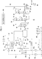
- the boiler plant of the present embodiment includes gas turbine equipment 10, a heat recovery system generator 20, steam turbine equipment 30, a power system facility 40, a carbon dioxide capture system 50, and a plant control device 100.
- the gas turbine equipment 10 includes a gas turbine 11, a fuel line 16 that guides fuel (fossil fuel) F to the gas turbine 11, a fuel regulating valve 17 that regulates the flow rate of the fuel F flowing through the fuel line 16, and a GT generator 19 that generates power by driving the gas turbine 11. Since the gas turbine equipment 10 includes the GT generator 19 as described above, the gas turbine equipment is also a gas turbine power generation facility.
- the gas turbine 11 includes an air compressor 12 that compresses air A to generate compressed air, a combustor 13 that combusts the fuel F in the compressed air to generate combustion gas, and a turbine 14 driven with the combustion gas.
- the air compressor 12 has a compressor rotor, and a compressor casing that covers the compressor rotor.
- the turbine 14 has a turbine rotor, and a turbine casing that covers the turbine rotor.
- the compressor rotor and the turbine rotor are coupled to each other to form a gas turbine rotor 15.
- the fuel line 16 is connected to the combustor 13.
- the fuel line 16 is provided with the fuel regulating valve 17.
- the heat recovery system generator 20 heats water with the heat of exhaust gas from the gas turbine 11 and turns the water into steam.
- the steam turbine equipment 30 includes a steam turbine 31 driven with the steam generated by the heat recovery system generator 20, a main steam line 32 that guides the steam generated by the heat recovery system generator 20 to the steam turbine 31, a steam regulating valve 33 that regulates the flow rate of the steam flowing into the steam turbine 31 from the main steam line 32, a temperature sensor 34 that detects the temperature of the steam flowing through the main steam line 32, a pressure sensor 35 that detects the pressure of the steam flowing through the main steam line 32, a condenser 36 that returns the steam exhausted from the steam turbine 31 to water, a supply water line 37 that guides the water in the condenser 36 to the heat recovery system generator 20, and an ST generator 39 that generates power by driving the steam turbine 31.
- the steam turbine equipment 30 includes the ST generator 39, the steam turbine equipment 30 is also a steam turbine power generation facility.
- the power system facility 40 includes a GT power system 41a that electrically connects the GT generator 19 to an external power system 48, a GT circuit breaker 42a provided in the GT power system 41a, a GT transformer 43a provided in the GT power system 41a, an ST power system 41b that electrically connects the ST generator 39 to the external power system 48, an ST circuit breaker 42b provided in the ST power system 41b, an ST transformer 43b provided in the ST power system 41b, an AC/DC converter 44 that converts alternating-current power flowing through the GT power system 41a and the ST power system 41b into direct-current power, a direct-current power system 45 connected to the AC/DC converter 44, and a solar power generation facility 46 connected to the direct-current power system 45.
- the solar power generation facility 46 includes a plurality of solar cells.
- a plurality of power generation facilities are electrically connected to the external power system 48.
- One power generation facility of the plurality of power generation facilities is a wind power generation facility 49.
- the wind power generation facility 49 includes a windmill.
- Both the solar power generation facility 46 and the wind power generation facility 49 are carbon-free power generation facilities.
- the carbon-free power generation facility is a facility that generates power by using the combustion gas generated through the combustion of the fossil fuel, for example, a facility that discharges carbon dioxide having a concentration lower than the carbon dioxide concentration in the exhaust gas from the gas turbine power generation facility 10 of the present embodiment or a facility that does not discharge the carbon dioxide during power generation.
- the solar power generation facility 46 and the wind power generation facility 49 are both facilities that generate power by using renewable energy.
- the plant control device 100 controls the opening and closing of the fuel regulating valve 17 and the steam regulating valve 33.
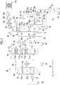
- the carbon dioxide capture system 50 includes a gas booster 51, an exhaust gas cooling device 60, an absorber 70, an absorbing-liquid regeneration device 80, and an exhaust gas recirculation line 52.
- the gas booster 51 boosts the pressure of the exhaust gas from the heat recovery system generator 20 to send the boosted exhaust gas to the exhaust gas cooling device 60.
- the exhaust gas cooling device 60 cools the exhaust gas from the gas booster 51.
- the exhaust gas cooling device 60 includes a cooling tower 61, a water circulation line 62, a water circulation pump 63, a water cooler 64, and a low-temperature exhaust gas line 65.
- the cooling tower 61 has a cooling tower container 61v and a filling material 61p disposed in an intermediate portion in the vertical direction in the cooling tower container 61v.
- the exhaust gas from the gas booster 51 is supplied to a position below a filling material 61p in the cooling tower container 61v.
- One end of the water circulation line 62 is connected to a lower end of the cooling tower container 61v, and the other end of the water circulation line 62 is connected to a position above the filling material 61p in the cooling tower container 61v.
- the water circulation pump 63 and the water cooler 64 are provided in the water circulation line 62.
- the water reserved at a bottom portion of the cooling tower container 61v flows into the water circulation pump 63 via the water circulation line 62.
- the water circulation pump 63 boosts the pressure of the water to send the boosted water to an upper portion in the cooling tower container 61v via the water circulation line 62. As a result, the water is sprayed into an upper space in the cooling tower container 61v.
- the water cooler 64 is a heat exchanger that cools the water by exchanging heat between the water flowing through the water circulation line 62 and a cooling medium. As the cooling medium, for example, cooling water is used.
- One end of the low-temperature exhaust gas line 65 is connected to an upper end of the cooling tower container 61v.
- One end of the exhaust gas recirculation line 52 is connected to the low-temperature exhaust gas line 65. Additionally, the other end of the exhaust gas recirculation line 52 is connected to a suction port of the air compressor 12 in the gas turbine equipment 10. In addition, the aforementioned gas booster 51 may be provided in the low-temperature exhaust gas line 65.
- the absorber 70 absorbs the carbon dioxide contained in the exhaust gas from the exhaust gas cooling device 60 into an absorbing liquid, and discharges the exhaust gas from which the carbon dioxide has been removed.
- the absorber 70 includes an absorption tower 71, an exhaust line 72, a lean absorbing-liquid line 73, a lean-rich heat exchanger 74, a lean absorbing-liquid pump 75, a lean absorbing-liquid cooler 76, a lean absorbing-liquid regulating valve 77, a rinse water circulation line 78, a rinse water circulation pump 79p, and a rinse water cooler 79r.
- the absorption tower 71 has an absorption tower container 71v, a lower filling material 71pa, an upper filling material 71pb, a lower demister 71da, an upper demister 71db, and a tray 71t.
- the lower filling material 71pa, the upper filling material 71pb, the lower demister 71da, the upper demister 71db, and the tray 71t are all disposed in the absorption tower container 71v.
- the lower filling material 71pa is disposed at a distance downward with respect to the upper filling material 71pb.
- the lower demister 71da is disposed in the vertical direction between the lower filling material 71pa and the upper filling material 71pb.
- the upper demister 71db is disposed above the upper filling material 71pb. Both the lower demister 71da and the upper demister 71db capture the moisture contained in the gas rising from the bottom to the top and suppress the rise of the moisture above themselves.
- the tray 71t is disposed in the vertical direction between the lower demister 71da and the upper filling material 71pb.
- the tray 71t is formed with a plurality of through-holes penetrating in the vertical direction and a water reservoir portion 71s in which the rinse water is reserved.
- the other end of the aforementioned low-temperature exhaust gas line 65 is connected to a position below the lower filling material 71pa in the absorption tower container 71v.
- the exhaust line 72 is connected to an upper end of the absorption tower container 71v.
- the exhaust gas that has passed through the absorption tower container 71v flows through the exhaust line 72.
- the exhaust gas is exhausted to the outside of the plant via a chimney or the like.
- One end of the rinse water circulation line 78 is connected to the water reservoir portion 71s in the absorption tower container 71v, and the other end of the rinse water circulation line 78 is connected to a position above the upper filling material 71pb and below the upper demister 71db, in the absorption tower container 71v.
- Both the rinse water circulation pump 79p and the rinse water cooler 79r are provided in the rinse water circulation line 78.
- the rinse water circulation pump 79p boosts the pressure of the rinse water flowing into the rinse water circulation line 78.
- the rinse water cooler 79r cools the rinse water that has flowed into the rinse water circulation line 78.
- a lean absorbing liquid flows through the lean absorbing-liquid line 73.
- the lean absorbing liquid is an absorbing liquid that absorbs a small amount of carbon dioxide.
- the rich absorbing liquid is an absorbing liquid that absorbs a large amount of carbon dioxide.
- the absorbing liquid is an amine-based absorbing liquid.
- alkanolamines such as monoethanolamine, diethanolamine, triethanolamine, methyldiethanolamine, diisopropanolamine, and diglycolamine can be adopted. Additionally, hindered amines can also be adopted. Additionally, each of these single aqueous solutions or mixed aqueous solutions of two or more of these can also be adopted.
- One end of the lean absorbing-liquid line 73 is connected to a position above the lower filling material 71pa and below the lower demister 71da, in the absorption tower container 71v. For this reason, the lean absorbing liquid that has flowed through the lean absorbing-liquid line 73 is sprayed in an intermediate space between the lower filling material 71pa and the lower demister 71da in the absorption tower container 71v.
- the lean-rich heat exchanger 74, the lean absorbing-liquid pump 75, the lean absorbing-liquid cooler 76, and the lean absorbing-liquid regulating valve 77 are all provided in the lean absorbing-liquid line 73.
- the lean-rich heat exchanger 74 heats the rich absorbing liquid while cooling the lean absorbing liquid by exchanging heat between the lean absorbing liquid and the rich absorbing liquid.
- the lean absorbing-liquid pump 75 boosts the pressure of the lean absorbing liquid flowing through the lean absorbing-liquid line 73.
- the lean absorbing-liquid cooler 76 is a heat exchanger that cools the lean absorbing liquid by exchanging heat between the lean absorbing liquid boosted by the lean absorbing-liquid pump 75 and the cooling medium. As the cooling medium, for example, cooling water is used.
- the lean absorbing-liquid regulating valve 77 regulates the flow rate of the lean absorbing liquid.
- the absorbing-liquid regeneration device 80 separates the carbon dioxide from the absorbing liquid that has absorbed the carbon dioxide from the absorber 70, that is, the rich absorbing liquid.
- the absorbing-liquid regeneration device 80 has a regenerator 81, a carbon dioxide recovery line 82, a cooler 82r, a moisture separation tank 82t, a carbon dioxide compressor 82c, a water pump 82p, a moisture recovery line 82w, a rich absorbing-liquid line 83, a rich absorbing-liquid pump 84, a rich absorbing-liquid regulating valve 85, a first circulation line 86, a second circulation line 87, a reboiler (heat exchanger) 89, a heater 90, a switcher 92, a switching controller 93, a temperature sensor 94, a second heating controller 95, a secondary battery 96, a charging and discharging controller 97, and a discharge system 98.
- the regenerator 81 has a regenerator container 81v, a filling material 81p disposed at an intermediate portion in the vertical direction in the regenerator container 81v, and a tray 81t disposed under the filling material 81p in the regenerator container 81v.
- the tray 81t is formed with a plurality of through-holes penetrating in the vertical direction and a liquid reservoir portion 81s in which the absorbing liquid is reserved.
- the other end of the aforementioned lean absorbing-liquid line 73 is connected to a lower end of the regenerator container 81v.
- the carbon dioxide recovery line 82 is connected to an upper end of the regenerator container 81v.
- a gas containing carbon dioxide flowing out of the regenerator container 81v flows through the carbon dioxide recovery line 82.
- the cooler 82r, the moisture separation tank 82t, and the carbon dioxide compressor 82c are provided in the carbon dioxide recovery line 82.
- the cooler 82r cools the gas containing carbon dioxide flowing out from the regenerator container 81v.
- the moisture separation tank 82t separates the moisture contained in this gas.
- the carbon dioxide compressor 82c compresses the gas from which most of the moisture has been removed.
- One end of the moisture recovery line 82w is connected to a lower end of the moisture separation tank 82t.
- the other end of the moisture recovery line 82w is connected to a position above the filling material 81p in the regenerator container 81v. For this reason, the water reserved in the moisture separation tank 82t is sprayed into an upper space in the regenerator container 81v.
- the water pump 82p is provided on the moisture recovery line 82w.
- the gas compressed by the carbon dioxide compressor 82c is sent to, for example, a carbon dioxide liquefaction facility where the gas is liquefied.
- One end of the rich absorbing-liquid line 83 is connected to a lower end of the aforementioned absorption tower container 71v, and the other end of the rich absorbing-liquid line 83 is connected to a position above the filling material 81p in the regenerator container 81v and below a connection position of the moisture recovery line 82w with respect to the regenerator container 81v. For this reason, the rich absorbing liquid from the rich absorbing-liquid line 83 is sprayed into the upper space in the regenerator container 81v.
- the rich absorbing-liquid pump 84 and the rich absorbing-liquid regulating valve 85 are provided in the rich absorbing-liquid line 83.
- the rich absorbing-liquid pump 84 boosts the pressure of the rich absorbing liquid flowing through the rich absorbing-liquid line 83.
- the rich absorbing-liquid regulating valve 85 regulates the flow rate of the rich absorbing liquid.
- the aforementioned lean-rich heat exchanger 74 is provided in the rich absorbing-liquid line 83.
- the lean-rich heat exchanger 74 exchanges heat between the lean absorbing liquid flowing through the lean absorbing-liquid line 73 and the rich absorbing liquid flowing through the rich absorbing-liquid line 83.
- the first circulation line 86 has an inflow-side sharing portion 86a including the aforementioned one end, an outflow-side sharing portion 86b including the aforementioned other end, and an intermediate portion 86c between the inflow-side sharing portion 86a and the outflow-side sharing portion 86b.
- a reboiler (heat exchanger) 89 is provided in the intermediate portion 86c in the first circulation line 86.
- a heating steam line 38 (refer to Fig.
- the reboiler 89 heats the absorbing liquid by exchanging heat between the absorbing liquid flowing through the intermediate portion 86c and the steam from the heating steam line 38.
- the second circulation line 87 has an inflow-side sharing portion 86a of the first circulation line 86, an outflow-side sharing portion 86b of the first circulation line 86, and an intermediate portion 87c between the inflow-side sharing portion 86a and the outflow-side sharing portion 86b. That is, the first circulation line 86 and the second circulation line 87 share an inflow-side portion and an outflow-side portion with each other.
- the intermediate portion 87c of the second circulation line 87 is independent of the intermediate portion 86c of the first circulation line 86.
- the heater 90 is provided in the intermediate portion 87c of the second circulation line 87.
- the heater 90 has a heating container 90v into which the absorbing liquid flowing through the intermediate portion 87c of the second circulation line 87 flows, and an electric heater 91 that heats the absorbing liquid in the heating container 90v.
- the electric heater 91 has an electric heater main body 91a that is a heat generating body, and a heater drive circuit 91b that supplies power to the electric heater main body 91a.
- the switcher 92 has a first shut-off valve 92a provided in the intermediate portion 86c of the first circulation line 86 and a second shut-off valve 92b provided in the intermediate portion 87c of the second circulation line 87.
- the switching controller 93 controls the opening and closing of the first shut-off valve 92a and the second shut-off valve 92b depending on the steam temperature detected by the temperature sensor 34 of the steam turbine equipment 30 and the steam pressure detected by the pressure sensor 35 of the steam turbine equipment 30.
- the switching controller 93 controls the opening and closing of the first shut-off valve 92a and the second shut-off valve 92b, it is possible to realize a first heating state in which the absorbing liquid is allowed to flow through the first circulation line 86 and the absorbing liquid can be heated by the reboiler 89 and a second heating state in which the absorbing liquid is allowed to flow through the second circulation line 87 and the absorbing liquid can be heated by the heater 90.
- the switching controller 93 instructs the switcher 92 to bring about the first heating state when the steam condition that the temperature of the steam sent from the heat recovery system generator 20 to the reboiler 89 is equal to or higher than a predetermined temperature Ts and the pressure of the steam is equal to or higher than a predetermined pressure is satisfied. Additionally, the switching controller 93 instructs the switcher 92 to bring about the second heating state when the steam sent from the heat recovery system generator 20 to the reboiler 89 does not satisfy the steam condition. In a case where the first heating state is realized, the switching controller 93 gives an opening instruction to the first shut-off valve 92a and gives a closing instruction to the second shut-off valve 92b.
- the switching controller 93 gives a closing instruction to the first shut-off valve 92a and gives an opening instruction to the second shut-off valve 92b.
- the switcher 92 is constituted by the first shut-off valve 92a and the second shut-off valve 92b, but the switcher 92 can also be constituted by one three-way valve. In this case, the three-way valve is provided at a connection portion between the intermediate portion 86c of the first circulation line 86 and the intermediate portion 87c of the second circulation line 87.
- the temperature sensor 94 is provided at a bottom portion of the regenerator container 81v.
- the temperature sensor 94 detects the temperature of the absorbing liquid reserved at a bottom portion in the regenerator container 81v.
- the second heating controller 95 controls the heating in the heater 90 depending on the absorbing liquid temperature detected by the temperature sensor 94. Specifically, an ON instruction or an OFF instruction is given to the heater drive circuit 91b depending on the absorbing liquid temperature.
- the discharge system 98 electrically connects the heater drive circuit 91b to the charging and discharging controller 97.
- the direct-current power system 45 and the secondary battery 96 are further electrically connected to the charging and discharging controller 97.
- the charging and discharging controller 97 charges the secondary battery 96 with the direct-current power from the direct-current power system 45 or discharges power from the secondary battery 96 depending on a state signal from the plant control device 100.
- the gas turbine rotor 15 When the gas turbine 11 is in steady operation, the gas turbine rotor 15 is rotating at a rated rotation speed. In this case, the air compressor 12 compresses the air to generate compressed air. The compressed air flows into the combustor 13. The fuel F is supplied to the combustor 13. The combustor 13 combusts the fuel F in the compressed air to generate a combustion gas. The turbine 14 is driven by the combustion gas. By driving the turbine 14, the GT generator 19 generates power. The power generated by the GT generator 19 is supplied to the external power system 48 via the GT circuit breaker 42a and the GT transformer 43a in the closed state.
- the heat recovery system generator 20 generates steam by using the heat of the exhaust gas.
- steam at a predetermined temperature or higher and a predetermined pressure or higher is generated in a predetermined amount or higher.
- the steam turbine rotor When the steam turbine 31 is in steady operation, the steam turbine rotor is rotating at a rated rotation speed.
- the ST generator 39 generates power by rotating the steam turbine rotor.
- the power generated by the ST generator 39 is supplied to the external power system 48 via the ST circuit breaker 42b and the ST transformer 43b in the closed state.
- the exhaust gas exhausted from the heat recovery system generator 20 flows into the carbon dioxide capture system 50.
- the exhaust gas boosted by the gas booster 51 flows into the cooling tower 61 of the exhaust gas cooling device 60 in the carbon dioxide capture system 50.
- the cooling tower 61 the exhaust gas is cooled to, for example, about 40°C.
- a part of the exhaust gas cooled in the cooling tower 61 flows into a lower space in the absorption tower container 71v via the low-temperature exhaust gas line 65. In this way, the reason why the exhaust gas is cooled is that the carbon dioxide is easily absorbed by the absorbing liquid.
- the other part of the exhaust gas cooled in the cooling tower 61 flows into the air compressor 12 of the gas turbine 11 via the low-temperature exhaust gas line 65 and the exhaust gas recirculation line 52.
- the air compressor 12 compresses not only the outside air but also the exhaust gas cooled in the cooling tower 61.
- the exhaust gas flows into the heat recovery system generator 20 again via the combustor 13 and the turbine 14.
- the carbon dioxide concentration in the exhaust gas exhausted from the heat recovery system generator 20 in other words, the exhaust gas flowing into the carbon dioxide capture system 50 becomes high.
- the carbon dioxide capture system 50 removes carbon dioxide from the exhaust gas having a high carbon dioxide concentration. For this reason, in the present embodiment, the carbon dioxide removal efficiency in the carbon dioxide capture system 50 can be enhanced.
- a lean absorbing liquid at 40°C is sprayed from the lean absorbing-liquid line 73.
- the lean absorbing liquid descends in the absorption tower container 71v. In the descending process, the lean absorbing liquid comes into contact with the exhaust gas and absorbs the carbon dioxide in the exhaust gas.
- the lean absorbing liquid becomes a rich absorbing liquid by absorbing the carbon dioxide and is temporarily reserved at a bottom portion in the absorption tower container 71v.
- the exhaust gas from which the carbon dioxide has been removed by the contact with the lean absorbing liquid rises and passes through the lower demister 71da.
- the moisture contained in the exhaust gas is removed in the process of passing through the lower demister 71da.
- the exhaust gas passes through the through-holes of the tray 71t and further rises.
- the water reserved in the water reservoir portion 71s of the tray 71t is boosted and cooled via the rinse water circulation pump 79p and the rinse water cooler 79r, and then enters a space above the upper filling material 71pb in the absorption tower container 71v and is sprayed as rinse water.
- the exhaust gas that has passed through the tray 71t comes into contact with the rinse water and is cooled in the process of passing through the upper filling material 71pb.
- a part of the rinse water is reserved in the water reservoir portion 71s of the tray 71t. Additionally, the rest of the rinse water passes through the tray 71t and is temporarily reserved as a part of the lean absorbing liquid at the bottom portion in the absorption tower container 71v.
- the exhaust gas cooled with the rinse water passes through the upper demister 71db.
- the moisture contained in the exhaust gas is removed in the process of passing through the upper demister 71db.
- the exhaust gas from which the carbon dioxide and the moisture have been removed is exhausted to the outside of the plant via the exhaust line 72.
- the rich absorbing liquid reserved at the bottom portion in the absorption tower container 71v flows into the rich absorbing-liquid line 83.
- the rich absorbing liquid is boosted by the rich absorbing-liquid pump 84 in the process of flowing through the rich absorbing-liquid line 83, and then heated by heat exchange with the lean absorbing liquid in the lean-rich heat exchanger 74.
- the heated rich absorbing liquid is sprayed into the upper space in the regenerator container 81v via the rich absorbing-liquid regulating valve 85.
- the rich absorbing liquid sprayed into the upper space in the regenerator container 81v is heated in contact with the steam in the regenerator container 81v, and the carbon dioxide in the rich absorbing liquid is separated.
- the carbon dioxide is sent to, for example, the carbon dioxide liquefaction facility via the carbon dioxide recovery line 82.
- the rich absorbing liquid becomes a lean absorbing liquid as the carbon dioxide is separated.
- a part of the lean absorbing liquid is reserved in the liquid reservoir portion 81s of the tray 81t. Additionally, the rest of the lean absorbing liquid is temporarily reserved at the bottom portion in the regenerator container 81v through the through-hole of the tray 81t.
- the lean absorbing liquid reserved in the liquid reservoir portion 81s in the regenerator container 81v flows into the reboiler 89 via the first circulation line 86.
- a part of the steam generated in the heat recovery system generator 20 flows into the reboiler 89 via the heating steam line 38.
- the lean absorbing liquid is heated to, for example, 120°C by heat exchange between the lean absorbing liquid and the steam.
- the lean absorbing liquid heated by the reboiler 89 flows into the regenerator container 81v via the first shut-off valve 92a in the open state.
- a part of the lean absorbing liquid becomes the steam in the regenerator container 81v and rises in the regenerator container 81v. Additionally, the rest of the lean absorbing liquid descends in the regenerator container 81v and is temporarily reserved at the bottom portion of the regenerator container 81v.
- the lean absorbing liquid reserved at the bottom portion in the regenerator container 81v flows into the lean absorbing-liquid line 73.
- the lean absorbing liquid is cooled by heat exchange with the rich absorbing liquid in the lean-rich heat exchanger 74 in the process of flowing through the lean absorbing-liquid line 73, and then boosted by the lean absorbing-liquid pump 75.
- the lean absorbing liquid is cooled to, for example, the aforementioned 40°C by the lean absorbing-liquid cooler 76, and then sprayed into an upper space in the absorption tower container 71v via the lean absorbing-liquid regulating valve 77.
- a fuel supply step Sfs a GT circuit breaker closing step Stbc, an ST circuit breaker closing step Ssbc, a chargeable step Sch, the absorption step Sab, an absorbing-liquid regeneration step Sre, and a first heating step Sh1 are executed.
- step Sfs fuel is supplied to the combustor 13 of the gas turbine 11. For this reason, during the fuel supply step Sfs, combustion gas is generated, and the combustion gas flows into the carbon dioxide capture system 50 as the exhaust gas via the heat recovery system generator 20.
- the GT circuit breaker closing step Stbc the GT circuit breaker 42a is closed, the GT generator 19 generates power, and the power in this case is supplied to the external power system 48.
- the ST circuit breaker closing step Ssbc the ST circuit breaker 42b is closed, the ST generator 39 generates power, and the power in this case is supplied to the external power system 48.
- the direct-current power system 45 and the secondary battery 96 are brought into an electrically connected state via the charging and discharging controller 97. For this reason, a chargeable state is brought about in which a part of the power from the GT generator 19, the ST generator 39, the solar power generation facility 46, and the wind power generation facility 49 electrically connected to the direct-current power system 45 is chargeable into the secondary battery 96 via the charging and discharging controller 97.
- the secondary battery 96 In the chargeable state, if the secondary battery 96 is not in a fully charged state, a part of the alternating-current power from the GT generator 19, the ST generator 39, and the wind power generation facility 49 may be converted into direct-current power by the AC/DC converter 44 and then charged into the secondary battery 96 via the direct-current power system 45 and the charging and discharging controller 97. Additionally, in the chargeable state, if the secondary battery 96 is not in the fully charged state, a part of the direct-current power from the solar power generation facility 46 may be charged into the secondary battery 96 via the direct-current power system 45 and the charging and discharging controller 97.
- the carbon dioxide capture system 50 absorbs the carbon dioxide contained in the exhaust gas exhausted from the heat recovery system generator 20 into the lean absorbing liquid, and brings about a state in which the exhaust gas from which the carbon dioxide has been removed can be discharged.
- the carbon dioxide capture system 50 brings about a state in which the carbon dioxide can be separated from the rich absorbing liquid that is an absorbing liquid that has absorbed the carbon dioxide. In this state, when the rich absorbing liquid flows into the regenerator 81, the carbon dioxide is separated from the rich aqueous solution, and the rich absorbing liquid becomes a lean absorbing liquid.
- the first heating step Sh1 is included in the absorbing-liquid regeneration step Sre.
- the absorbing-liquid regeneration device 80 brings about the first heating state in which the absorbing liquid flows through the first circulation line 86 and the absorbing liquid can be heated by the reboiler 89.
- the first shut-off valve 92a and the second shut-off valve 92b constituting the switcher 92 the first shut-off valve 92a is open and the second shut-off valve 92b is closed.
- the absorbing liquid reserved in the liquid reservoir portion 81s in the regenerator container 81v flows into the reboiler 89 via the first circulation line 86.
- the absorbing liquid is heated by the steam from the heat recovery system generator 20 in the reboiler 89.
- the heated absorbing liquid returns to the inside of the regenerator 81 via the first circulation line 86 and the first shut-off valve 92a in the open state.
- the fuel supply to the combustor 13 of the gas turbine 11 is stopped (fuel supply stop step Sfc), and the GT circuit breaker 42a is opened (GT circuit breaker opening step Stbo).
- the fuel supply stop step Sfc is executed when the plant control device 100 gives a closing instruction to the fuel regulating valve 17.
- the GT circuit breaker opening step Stbo is executed by the plant control device 100 giving an opening instruction to the GT circuit breaker 42a.
- the flow rate of the steam generated by the heat recovery system generator 20 is maintained at the value during the steady operation of the gas turbine 11 for a predetermined time, but decreases gradually. Additionally, when the fuel supply to the combustor 13 is stopped, the temperature and pressure of the steam generated by the heat recovery system generator 20 are also maintained at the values during the steady operation of the gas turbine 11 for a predetermined time, but decrease gradually. For this reason, the steady operation of the steam turbine 31 cannot be performed.
- the ST circuit breaker 42b opens at the same time as the fuel supply to the combustor 13 of the gas turbine 11 is stopped or after a predetermined time after the fuel supply is stopped (ST circuit breaker opening step Ssbo).
- the ST circuit breaker opening step Ssbo is executed by the plant control device 100 giving an opening instruction to the ST circuit breaker 42b.
- the ST circuit breaker closing step Ssbc is executed, power is no longer supplied from the ST generator 39 to the external power system 48.
- the absorbing-liquid regeneration device 80 is brought into the second heating state in which the absorbing liquid flows through the second circulation line 87 and the absorbing liquid is heated by the heater 90 (second heating step Sh2).
- the switching controller 93 determines that the steam condition is no longer satisfied and instructs the switcher 92 to bring about the second heating state.
- the second heating state is brought about in which, in the first shut-off valve 92a and the second shut-off valve 92b constituting the switcher 92, the first shut-off valve 92a is closed and the second shut-off valve 92b is opened.
- the absorbing liquid reserved in the liquid reservoir portion 81s in the regenerator container 81v flows into the heater 90 via the second circulation line 87.
- the absorbing liquid may be heated by the electric heater 91 in the heater 90.
- the heated absorbing liquid returns to the inside of the regenerator container 81v via the second circulation line 87 and the second shut-off valve 92b in the open state.
- the second heating control step Sh2c is executed.
- the second heating controller 95 controls the heating in the heater 90 depending on the absorbing liquid temperature detected by the temperature sensor 94.
- a predetermined first temperature for example, 100°C
- the second heating controller 95 gives an ON instruction to the heater drive circuit 91b.
- a predetermined second temperature for example, 120°C
- the heater drive circuit 91b When an ON instruction is input to the heater drive circuit 91b, the power discharged from the secondary battery 96 is supplied to the electric heater main body 91a, the electric heater main body 91a generates heat, and the absorbing liquid flowing through the second circulation line 87 is heated. Additionally, when an OFF instruction is input to the heater drive circuit 91b, power is no longer supplied from the secondary battery 96 to the electric heater main body 91a, and the electric heater main body 91a no longer generates heat. Thus, in the second heating step Sh2, the temperature of the absorbing liquid in the regenerator 81 fluctuates between the first temperature Tab1 and the second temperature Tab2.
- the temperature of the absorbing liquid in the regenerator 81 is maintained at substantially the first temperature Tab1 (for example, 100°C) or higher.
- the gas turbine 11 When fuel is no longer supplied to the gas turbine 11, the gas turbine 11 is stopped, the heat recovery system generator 20 no longer generates steam, the steam turbine 31 is stopped, and then the fuel supply to the gas turbine 11 is started (fuel supply step Sfs), combustion gas is generated, and the rotation speed of the gas turbine rotor 15 increases gradually.
- the rotation speed of the gas turbine rotor 15 reaches the rated rotation speed (for example, 3600 rpm)
- the GT circuit breaker 42a is closed (GT circuit breaker closing step Stbc)
- the GT generator 19 generates power, and the power in this case is supplied to the external power system 48.
- the exhaust gas which is the combustion gas exhausted from the gas turbine 11, flows into the heat recovery system generator 20.
- the heat recovery system generator 20 turns water into steam by using the heat of the exhaust gas.
- the temperature and pressure of the steam increase gradually.
- the absorbing-liquid regeneration device 80 is brought into the first heating state in which the absorbing liquid flows through the first circulation line 86 and the reboiler 89 heats the absorbing liquid (first heating step Sh1).
- the switching controller 93 determines that the steam condition is satisfied and instructs the switcher 92 to bring about the first heating state.
- the first heating state is brought about in which, in the first shut-off valve 92a and the second shut-off valve 92b constituting the switcher 92, the first shut-off valve 92a is opened and the second shut-off valve 92b is closed.
- the absorbing liquid reserved in the liquid reservoir portion 81s in the regenerator container 81v flows into the reboiler 89 via the first circulation line 86.
- the absorbing liquid is heated by the steam from the heat recovery system generator 20 in the reboiler 89.
- the heated absorbing liquid returns to the inside of the regenerator container 81v via the first circulation line 86 and the first shut-off valve 92a in the open state.
- the GT generator 19 since the GT generator 19 generates power when the steam generated by the heat recovery system generator 20 satisfies the steam condition, the dischargeable step Sdch is switched to the chargeable step Sch from this point of time. Additionally, when the steam generated by the heat recovery system generator 20 satisfies the steam condition and the rotation speed of the steam turbine 31 reaches the rated rotation speed, the ST circuit breaker 42b is closed (ST circuit breaker closing step Ssbc), and power can be supplied from the ST generator 39 to the external power system 48.
- the second heating step Sh2 is executed in the absorbing-liquid regeneration step Sre, and the temperature of the absorbing liquid in the regenerator 81 is maintained at substantially the first temperature Tab1 (for example, 100°C) or higher.
- the temperature of the absorbing liquid in the regenerator 81 is lower than an appropriate temperature (for example, 120°C) for separating the carbon dioxide from the absorbing liquid. For this reason, in the regenerator 81, the ability to separate the carbon dioxide from the absorbing liquid decreases.
- the amount of the carbon dioxide contained in the lean absorbing liquid sent from the regenerator 81 to the absorption tower 71 is larger than that when the steam turbine 31 and the heat recovery system generator 20 are in steady operation. Therefore, at the time of the start-up, the absorption rate of the carbon dioxide in the exhaust gas in the absorber 70 is lower than that when the steam turbine 31 and the heat recovery system generator 20 are in steady operation.
- the absorber 70 since the absorber 70 absorbs the carbon dioxide in the exhaust gas into the absorbing liquid and executes the regeneration of the absorbing liquid that has absorbed the carbon dioxide even at the time of the start-up, the amount of discharge of the carbon dioxide can be suppressed when the heat recovery system generator 20 is started.
- the temperature of the absorbing liquid in the regenerator 81 is lower than the appropriate temperature (for example, 120°C) for separating the carbon dioxide.
- the temperature of the absorbing liquid in the absorption tower 71 in this case is substantially equal to or higher than the first temperature Tab1 (for example, 100°C), the temperature of the absorbing liquid in the absorption tower 71 can be set to the appropriate temperature (for example, 120°C) for separating the carbon dioxide, within a short time after being switched to the first heating state.
- the amount of discharge of the carbon dioxide immediately after the absorbing-liquid regeneration device 80 is switched from the second heating state to the first heating state can be suppressed.
- the absorbing-liquid regeneration device 80 when the absorbing-liquid regeneration device 80 is in the second heating state, the absorbing liquid is not always heated by the heater 90. Therefore, the consumption of electric energy in the heater 90 can be suppressed.
- the boiler plant of the present embodiment includes the gas turbine power generation facility 10 including the GT generator 19 and the steam turbine power generation facility 30 including the ST generator 39, but further includes the carbon dioxide capture system 50.
- the carbon dioxide in the exhaust gas exhausted from the boiler plant is little.
- the discharge of the carbon dioxide when generating the power for charging the secondary battery 96 can be suppressed.
- the boiler of the present embodiment is the heat recovery system generator 20 that generates steam with the heat of the exhaust gas from the gas turbine 11.
- the boiler may be a general boiler having a combustion chamber for combusting fossil fuel.
- the steam turbine 31 may include a plurality of steam turbines 31 in which the pressures of inflowing steam are different from each other.
- the GT generator 19 and the ST generator 39 are independent generators.
- one generator may be connected to the rotors, and the generator may serve as both a generator for the gas turbine 11 and a generator for the steam turbine 31.
- the heater 90 of the present embodiment has the electric heater 91, and the energy for heating the absorbing liquid with the heater 90 is electric energy.
- the energy for heating the absorbing liquid with the heater 90 may not be the electric energy, and may be, for example, the thermal energy of steam.
- a boiler or the like that generates steam independently of the heat recovery system generator 20 is required.
- the temperature of the absorbing liquid in the regenerator 81 is controlled to fluctuate between the first temperature Tab1 and the second temperature Tab2.
- the temperature of the absorbing liquid in the regenerator 81 may be controlled to be, for example, a third temperature between the first temperature Tab1 and the second temperature Tab2.
- the first circulation line 86 and the second circulation line 87 in the present embodiment share a part with each other.
- the first circulation line 86 and the second circulation line 87 may be completely independent of each other.
- the switching controller 93 and the second heating controller 95 in the present embodiment are present separately from the plant control device 100. However, the switching controller 93 and the second heating controller 95 may be incorporated in the plant control device 100.
- the chargeable step Sch when the GT generator 19 or the ST generator 39 no longer generates power, the chargeable step Sch ends. However, if another power generation facility in the plant or a power generation facility connected to the external power system 48 is in operation and there is surplus power, the chargeable step Sch may not be ended. That is, in a case where there is surplus power, the chargeable step Sch may be continued.
- the boiler plant when the GT generator 19 and the ST generator 39 no longer generate power and the steam generated by the heat recovery system generator 20 no longer satisfies the steam condition, the boiler plant is brought into the dischargeable state (dischargeable step Sdch). For this reason, in the present embodiment, the chargeable step Sch and the dischargeable step Sdch are not executed in the same time zone. However, if the secondary battery 96 has a function capable of simultaneously performing charging and discharging, the execution time zone of the chargeable step Sch and the execution time zone of the dischargeable step Sdch may partially overlap each other. In this case, the start timing of the dischargeable step Sdch may coincide with the end timing of the chargeable step Sch in the present embodiment, or may be earlier than the end timing of the chargeable step Sch in the present embodiment.
- the boiler plant in the above embodiment is grasped as follows, for example.
- the carbon dioxide capture system 50 has an absorbing-liquid regeneration device 80 that separates the carbon dioxide from an absorbing liquid that has absorbed the carbon dioxide, and an absorber 70 that allows the exhaust gas from the boiler 20 to flow thereinto, absorbs the carbon dioxide in the exhaust gas in the absorbing liquid from the absorbing-liquid regeneration device, and discharges the exhaust gas from which the carbon dioxide has been removed.
- the absorbing-liquid regeneration device 80 has a regenerator 81 that allows the absorbing liquid, which has absorbed the carbon dioxide in the absorber 70, to flow thereinto, separates the carbon dioxide from the absorbing liquid in a high-temperature environment to discharge the carbon dioxide, and returns the absorbing liquid from which the carbon dioxide has been separated to the absorber 70, a first circulation line 86 that takes out the absorbing liquid from an inside of the regenerator 81 and then returns the taken-out absorbing liquid to the inside of the regenerator 81, a second circulation line 87 that takes out the absorbing liquid from the inside of the regenerator 81 and then returns the taken-out absorbing liquid to the inside of the regenerator 81, a heat exchanger 89 that is provided in the first circulation line 86 to heat the absorbing liquid by exchanging heat between the absorbing liquid flowing through the first circulation line 86 and the steam from the boiler 20, a heater 90 that is provided in the second circulation line 87 to heat the absorbing liquid flowing through the second circulation line 87, and a switcher 92
- the absorbing-liquid regeneration device 80 when the steam condition that the temperature of the steam sent from the boiler 20 to the heat exchanger 89 is equal to or higher than a predetermined temperature and the pressure of the steam is equal to or higher than a predetermined pressure is satisfied, the absorbing-liquid regeneration device 80 is brought into the first heating state. In the first heating state, the absorbing liquid is heated with the steam from the boiler 20 in the heat exchanger 89. As the absorbing liquid is heated, the inside of the regenerator 81 becomes a high-temperature environment, and the carbon dioxide is separated from the absorbing liquid. The absorbing liquid from which the carbon dioxide has been separated is supplied to the absorber 70.
- the carbon dioxide in the exhaust gas from the heat recovery system generator 20 is absorbed by the absorbing liquid, and the exhaust gas from which the carbon dioxide has been removed is discharged.
- the carbon dioxide contained in the exhaust gas exhausted from the plant can be reduced.
- the absorbing-liquid regeneration device 80 when the steam sent from the boiler 20 to the heat exchanger 89 does not satisfy the steam condition, the absorbing-liquid regeneration device 80 is brought into the second heating state. In the second heating state, the absorbing liquid is heated by the heater 90. As the absorbing liquid is heated, the inside of the regenerator 81 becomes a high-temperature environment, and the carbon dioxide is separated from the absorbing liquid. The absorbing liquid from which the carbon dioxide has been separated is supplied to the absorber 70. In the absorber 70, the carbon dioxide in the exhaust gas from the boiler 20 is absorbed by the absorbing liquid, and the exhaust gas from which the carbon dioxide has been removed is discharged.
- the carbon dioxide contained in the exhaust gas exhausted from the plant can be reduced.
- the temperature of the absorbing liquid in the regenerator 81 is equal to or higher than the predetermined temperature. Therefore, even immediately after the second heating state is switched to the first heating state, the temperature of the absorbing liquid in the regenerator 81 can be raised to a target temperature within a short time. For this reason, in the present aspect, it is possible to reduce the amount of the carbon dioxide contained in the exhaust gas exhausted from the plant even immediately after the second heating state is switched to the first heating state.
- the absorbing-liquid regeneration device 80 has a switching controller 93 that instructs the switcher 92 to bring about the first heating state when a steam condition that a temperature of the steam sent from the boiler 20 to the heat exchanger 89 is equal to or higher than a predetermined temperature and a pressure of the steam is equal to or higher than a predetermined pressure is satisfied, and instructs the switcher 92 to bring about the second heating state when the steam condition is not satisfied.
- the first heating state when the steam sent from the boiler 20 to the heat exchanger 89 satisfies the steam condition, the first heating state can be automatically brought about. Additionally, in the present aspect, when the steam sent from the boiler 20 to the heat exchanger 89 does not satisfy the steam condition, the second heating state can be automatically brought about.
- the absorbing-liquid regeneration device 80 has a temperature sensor 94 that detects a temperature of the absorbing liquid reserved in the regenerator 81, and a second heating controller 95 that heats the absorbing liquid by the heater 90 when the temperature detected by the temperature sensor 94 becomes lower than a predetermined temperature in the second heating state.
- the absorbing liquid is not always heated by the heater 90. Therefore, the consumption of thermal energy in the heater 90 can be suppressed.
- the absorbing-liquid regeneration device 80 has a secondary battery 96, and a charging and discharging controller 97 that controls charging and discharging of the secondary battery 96.
- the heater 90 has an electric heater 91 that generates heat by supplying power from the secondary battery 96.
- the electric heater 91 can be heated with the power charged in the secondary battery 96.
- the charging and discharging controller 97 brings about a chargeable state in which a power generation facility and the secondary battery 96 are electrically connected to each other such that power is chargeable from the power generation facility to the secondary battery 96 when the power generation facility is generating power, and brings about a dischargeable state in which the secondary battery 96 and the electric heater 91 are electrically connected to each other such that power is dischargeable from the secondary battery 96 to the electric heater 91 when the steam condition is not satisfied.
- the power generation facility when the power generation facility is generating power, if the secondary battery 96 is not in a fully charged state, the power from the power generation facility can be charged in the secondary battery 96. Additionally, in the present aspect, when the steam sent from the boiler 20 to the heat exchanger 89 does not satisfy the steam condition, the electric heater 91 can be heated with the power charged in the secondary battery 96.
- the boiler plant in a sixth aspect according to the boiler plant of the fifth aspect further includes a steam turbine 31 that is driven with the steam from the boiler 20, and a generator 39 that generates power by driving the steam turbine 31.
- the power generation facility includes the generator 39.
- the power from the generator 39 can be charged in the secondary battery 96.
- the power generation facility includes a carbon-free power generation facility
- the carbon-free power generation facility is a facility that discharges carbon dioxide having a concentration lower than the carbon dioxide concentration in the exhaust gas from a facility that generates power by using the combustion gas generated through the combustion of the fossil fuel, or a facility that does not discharge the carbon dioxide during power generation.
- the discharge of the carbon dioxide when generating the power for charging the secondary battery 96 can be suppressed.
- the boiler plant in an eighth aspect according to the boiler plant of any one of the first aspect to the seventh aspect further includes a gas turbine 11 that is driven with the combustion gas generated through the combustion of the fossil fuel F.
- the boiler 20 is a heat recovery system generator that generates steam with heat of the combustion gas exhausted from the gas turbine 11.
- a carbon dioxide removal method in a ninth aspect executes an absorbing-liquid regeneration step Sre in which carbon dioxide is separable from an absorbing liquid that has absorbed the carbon dioxide, and an absorption step Sab in which an exhaust gas from a boiler 20 flows in, the carbon dioxide in the exhaust gas is absorbed in the absorbing liquid processed in the absorbing-liquid regeneration step Sre, and the exhaust gas from which the carbon dioxide has been removed is capable of being discharged.
- the absorbing-liquid regeneration step Sre is executed by an absorbing-liquid regeneration device 80.
- the absorbing-liquid regeneration device 80 has a regenerator 81 that allows the absorbing liquid, which has absorbed the carbon dioxide through an execution of the absorption step Sab, to flow thereinto, separates the carbon dioxide from the absorbing liquid in a high-temperature environment to discharge the carbon dioxide, and causes the absorbing liquid from which the carbon dioxide has been separated to be used in the absorption step Sab, a first circulation line 86 that takes out the absorbing liquid from an inside of the regenerator 81 and then returns the taken-out absorbing liquid to the inside of the regenerator 81, a second circulation line 87 that takes out the absorbing liquid from the inside of the regenerator 81 and then returns the taken-out absorbing liquid to the inside of the regenerator 81, a heat exchanger 89 that is provided in the first circulation line 86 to heat the absorbing liquid by exchanging heat between the absorbing liquid flowing through the first circulation line 86 and steam from the boiler 20, and a heater 90 that
- the absorbing-liquid regeneration step Sre includes a first heating step Sh1 in which the absorbing liquid flows through the first circulation line 86 such that the absorbing liquid is heatable by the heat exchanger 89, and a second heating step Sh2 in which the absorbing liquid flows through the second circulation line 87 such that the absorbing liquid is heatable by the heater 90.
- the second heating step Sh2 includes a second heating control step Sh2c in which the absorbing liquid is heated by the heater 90 when a temperature of the absorbing liquid reserved in the regenerator 81 becomes lower than a predetermined temperature.
- the absorbing-liquid regeneration device 80 has a secondary battery 96
- the heater 90 has an electric heater 91 that generates heat by supplying power from the secondary battery 96.
- the absorbing-liquid regeneration step Sre includes a chargeable step Sch in which the secondary battery 96 is chargeable and a dischargeable step Sdch in which the secondary battery 96 is dischargeable to the electric heater 91.
- a power generation facility and the secondary battery 96 are electrically connected to each other such that power is chargeable from the power generation facility to the secondary battery 96 when the power generation facility is generating power.
- the secondary battery 96 and the electric heater 91 are electrically connected to each other such that power is dischargeable from the secondary battery 96 to the electric heater 91 when the steam condition is not satisfied.
- the power generation facility includes a carbon-free power generation facility.
- the carbon-free power generation facility is a facility that discharges carbon dioxide having a concentration lower than the carbon dioxide concentration in the exhaust gas from a facility that generates power by using the combustion gas generated through the combustion of the fossil fuel, or a facility that does not discharge the carbon dioxide during power generation.
- the carbon-free power generation facility is a facility that discharges carbon dioxide having a concentration lower than the carbon dioxide concentration in the exhaust gas from a facility that generates power by using the combustion gas generated through the combustion of the fossil fuel, or a facility that does not dischargethe carbon dioxide during power generation
- the carbon-free power generation facility includes a facility that generates power by using renewable energy.
- the carbon dioxide in the exhaust gas exhausted from the plant can be reduced even in the process of starting the boiler.
Landscapes
- Engineering & Computer Science (AREA)
- Chemical & Material Sciences (AREA)
- Analytical Chemistry (AREA)
- General Chemical & Material Sciences (AREA)
- Oil, Petroleum & Natural Gas (AREA)
- Chemical Kinetics & Catalysis (AREA)
- Mechanical Engineering (AREA)
- General Engineering & Computer Science (AREA)
- Combustion & Propulsion (AREA)
- Health & Medical Sciences (AREA)
- Biomedical Technology (AREA)
- Environmental & Geological Engineering (AREA)
- Treating Waste Gases (AREA)
- Gas Separation By Absorption (AREA)
- Engine Equipment That Uses Special Cycles (AREA)
- Chimneys And Flues (AREA)
Abstract
Description
- The present invention relates to a boiler plant including a boiler and a carbon dioxide capture system for removing carbon dioxide contained in an exhaust gas from the boiler, and a carbon dioxide removal method for removing the carbon dioxide contained in the exhaust gas.
- Priority is claimed on
Japanese Patent Application No. 2019-238846 filed on December 27, 2019 - An exhaust gas containing carbon dioxide is discharged from a boiler that generates steam with the heat of a combustion gas generated through the combustion of fossil fuel. From the viewpoint of environmental protection, a technique for removing the carbon dioxide from the exhaust gas as much as possible is required. As such a technique, for example, the plant described in Patent Document 1 below is known.
- The plant described in Patent Document 1 has an absorber that absorbs carbon dioxide in an exhaust gas into an absorbing liquid and discharges the exhaust gas from which the carbon dioxide has been removed, and an absorbing-liquid regeneration device that separates the carbon dioxide from the absorbing liquid that has absorbed the carbon dioxide. The absorbing-liquid regeneration device includes a regenerator, a circulation line, and a heat exchanger (or reboiler). The regenerator allows the absorbing liquid, which has absorbed the carbon dioxide from the absorber, to flow thereinto, separates the carbon dioxide from the absorbing liquid in a high-temperature environment to exhaust the carbon dioxide, and returns the absorbing liquid from which the carbon dioxide has been separated to the absorber. The circulation line is a line that takes out the absorbing liquid from an inside of the regenerator and then returns the taken-out absorbing liquid to the inside of the regenerator. The heat exchanger (or reboiler) is provided in the circulation line to heat the absorbing liquid by exchanging heat between the absorbing liquid flowing through the circulation line and the steam. The plant further has a heat amount regulating unit that regulates the amount of heat input to the heat exchanger (or reboiler) . The heat amount regulating unit specifically regulates the flow rate of the steam that is a target for heat exchange with the absorbing liquid.
- [PTL 1]
Japanese Unexamined Patent Application Publication No. 2015-104693 - The steam generated in the boiler may be used as the target for heat exchange with the absorbing liquid in the heat exchanger (or reboiler). In this case, if there is no the steam supply from the boiler, the absorbing liquid cannot be heated by the heat exchanger, and the temperature of the absorbing liquid in the regenerator and the heat exchanger cannot be raised. In a case where the temperature of the absorbing liquid in the regenerator and the heat exchanger is low, the carbon dioxide is not separated from the absorbing liquid in the regenerator, and the absorbing liquid is not regenerated. As a result, the carbon dioxide contained in the exhaust gas from the boiler cannot be removed unless the steam is supplied from the boiler.
- In a general boiler, when fuel starts to be charged into the boiler, an exhaust gas containing carbon dioxide starts to be exhausted immediately from the boiler, while steam equal to or higher than a predetermined temperature and equal to or higher than a predetermined pressure is not generated immediately. Additionally, in a heat recovery system generator that generates steam by using the heat of the exhaust gas from a gas turbine, when the fuel starts to be charged into the gas turbine, the exhaust gas containing carbon dioxide starts to be exhausted immediately from the heat recovery system generator, while the steam equal to or higher than a predetermined temperature and equal to or higher than a predetermined pressure is not generated immediately. That is, in both a general boiler and a heat recovery system generator, there is a time lag between the start of exhaust of the exhaust gas and the start of generation of the steam equal to or higher than a predetermined temperature and equal to or higher than a predetermined pressure. For this reason, the absorbing liquid cannot be sufficiently heated by the heat exchanger for a predetermined time after the combustion gas starts to be exhausted from the boiler, and the carbon dioxide contained in the exhaust gas from the boiler cannot be removed.
- Thus, an object of the present invention is to provide a boiler plant capable of reducing carbon dioxide in an exhaust gas exhausted from the plant even in the process of starting the boiler, and a carbon dioxide removal method.
- A boiler plant as one aspect according to the invention for achieving the above object includes a boiler that generates steam with heat of a combustion gas generated through combustion of a fossil fuel, and a carbon dioxide capture system that removes carbon dioxide contained in an exhaust gas exhausted from the boiler.
- The carbon dioxide capture system includes an absorbing-liquid regeneration device that separates the carbon dioxide from an absorbing liquid that has absorbed the carbon dioxide, and an absorber that allows the exhaust gas from the boiler to flow thereinto, absorbs the carbon dioxide in the exhaust gas in the absorbing liquid from the absorbing-liquid regeneration device, and discharges the exhaust gas from which the carbon dioxide has been removed. The absorbing-liquid regeneration device includes a regenerator that allows the absorbing liquid, which has absorbed the carbon dioxide in the absorber, to flow thereinto, separates the carbon dioxide from the absorbing liquid in a high-temperature environment to discharge the carbon dioxide, and returns the absorbing liquid from which the carbon dioxide has been separated to the absorber, a first circulation line that takes out the absorbing liquid from an inside of the regenerator and then returns the taken-out absorbing liquid to the inside of the regenerator, a second circulation line that takes out the absorbing liquid from the inside of the regenerator and then returns the taken-out absorbing liquid to the inside of the regenerator, a heat exchanger that is provided in the first circulation line to heat the absorbing liquid by exchanging heat between the absorbing liquid flowing through the first circulation line and the steam from the boiler, a heater that is provided in the second circulation line to heat the absorbing liquid flowing through the second circulation line, and a switcher that switches between a first heating state in which the absorbing liquid flows through the first circulation line and a second heating state in which the absorbing liquid flows through the second circulation line.
- In the present aspect, when the steam condition that the temperature of the steam sent from the boiler to the heat exchanger is equal to or higher than a predetermined temperature and the pressure of the steam is equal to or higher than a predetermined pressure is satisfied, the absorbing-liquid regeneration device is brought into the first heating state. In the first heating state, the absorbing liquid is heated with the steam from the boiler in the heat exchanger. As the absorbing liquid is heated, the inside of the regenerator becomes a high-temperature environment, and the carbon dioxide is separated from the absorbing liquid. The absorbing liquid from which the carbon dioxide has been separated is supplied to the absorber. In the absorber, the carbon dioxide in the exhaust gas from the boiler is absorbed by the absorbing liquid, and the exhaust gas from which the carbon dioxide has been removed is discharged. Thus, in the present aspect, when the steam from the boiler satisfies the steam condition, the carbon dioxide contained in the exhaust gas exhausted from the plant can be reduced.
- In the present aspect, the absorbing-liquid regeneration device is brought into the second heating state when the steam sent from the boiler to the heat exchanger does not satisfy the steam condition (the temperature of the steam sent from the boiler to the heat exchanger is equal to or higher than a predetermined temperature and the pressure of the steam is equal to or higher than a predetermined pressure), for example, in the process of stopping or starting the boiler. In the second heating state, the absorbing liquid is heated by the heater. As the absorbing liquid is heated, the inside of the regenerator becomes a high-temperature environment, and the carbon dioxide is separated from the absorbing liquid. The absorbing liquid from which the carbon dioxide has been separated is supplied to the absorber. In the absorber, the carbon dioxide in the exhaust gas from the boiler is absorbed by the absorbing liquid, and the exhaust gas from which the carbon dioxide has been removed is discharged. Additionally, in the present aspect, even when the second heating state is switched to the first heating state, the temperature of the absorbing liquid in the regenerator is equal to or higher than the predetermined temperature, so that the second heating state is switched to the first heating state. Even immediately after that, the temperature of the absorbing liquid in the regenerator can be raised to the target temperature in a short time, and the carbon dioxide contained in the exhaust gas exhausted from the plant can be reduced.
- A carbon dioxide removal method as one aspect according to the invention for achieving the above object includes an absorbing-liquid regeneration step in which carbon dioxide is separable from an absorbing liquid that has absorbed the carbon dioxide, and an absorption step in which the exhaust gas from the boiler flows in, the carbon dioxide in the exhaust gas is absorbed in the absorbing liquid processed in the absorbing-liquid regeneration step, and the exhaust gas from which the carbon dioxide has been removed is capable of being discharged.
- The absorbing-liquid regeneration step is executed by the absorbing-liquid regeneration device. The absorbing-liquid regeneration device includes a regenerator that allows the absorbing liquid, which has absorbed the carbon dioxide through the execution of the absorption step, to flow thereinto, separates the carbon dioxide from the absorbing liquid in a high-temperature environment to discharge the carbon dioxide, and causes the absorbing liquid from which the carbon dioxide has been separated to be used in the absorption step, a first circulation line that takes out the absorbing liquid from an inside of the regenerator and then returns the taken-out absorbing liquid to the inside of the regenerator, a second circulation line that takes out the absorbing liquid from the inside of the regenerator and then returns the taken-out absorbing liquid to the inside of the regenerator, a heat exchanger that is provided in the first circulation line to heat the absorbing liquid by exchanging heat between the absorbing liquid flowing through the first circulation line and the steam from the boiler, and a heater that is provided in the second circulation line to heat the absorbing liquid flowing through the second circulation line. The absorbing-liquid regeneration step includes a first heating step in which the absorbing liquid flows through the first circulation line such that the absorbing liquid is heatable by the heat exchanger, and a second heating step in which the absorbing liquid flows through the second circulation line such that the absorbing liquid is heatable by the heater.
- According to one aspect of the present invention, the carbon dioxide in the exhaust gas exhausted from the plant can be reduced even in the process of starting the boiler.
-
-
Fig. 1 is a system diagram of a boiler plant according to an embodiment of the present invention. -
Fig. 2 is a system diagram of a carbon dioxide capture system according to the embodiment of the present invention. -
Fig. 3 is a timing chart showing the execution timings of a plurality of steps executed by the boiler plant according to the embodiment of the present invention. - Hereinafter, an embodiment and a modification example of the boiler plant according to the present invention will be described below with reference to the drawings.
- A boiler plant of the present embodiment will be described with reference to
Figs. 1 to 3 . - As shown in
Fig. 1 , the boiler plant of the present embodiment includesgas turbine equipment 10, a heatrecovery system generator 20,steam turbine equipment 30, apower system facility 40, a carbondioxide capture system 50, and aplant control device 100. - The
gas turbine equipment 10 includes agas turbine 11, afuel line 16 that guides fuel (fossil fuel) F to thegas turbine 11, afuel regulating valve 17 that regulates the flow rate of the fuel F flowing through thefuel line 16, and aGT generator 19 that generates power by driving thegas turbine 11. Since thegas turbine equipment 10 includes theGT generator 19 as described above, the gas turbine equipment is also a gas turbine power generation facility. - The
gas turbine 11 includes anair compressor 12 that compresses air A to generate compressed air, acombustor 13 that combusts the fuel F in the compressed air to generate combustion gas, and aturbine 14 driven with the combustion gas. Theair compressor 12 has a compressor rotor, and a compressor casing that covers the compressor rotor. Theturbine 14 has a turbine rotor, and a turbine casing that covers the turbine rotor. The compressor rotor and the turbine rotor are coupled to each other to form agas turbine rotor 15. Thefuel line 16 is connected to thecombustor 13. Thefuel line 16 is provided with thefuel regulating valve 17. - The heat
recovery system generator 20 heats water with the heat of exhaust gas from thegas turbine 11 and turns the water into steam. - The
steam turbine equipment 30 includes asteam turbine 31 driven with the steam generated by the heatrecovery system generator 20, amain steam line 32 that guides the steam generated by the heatrecovery system generator 20 to thesteam turbine 31, asteam regulating valve 33 that regulates the flow rate of the steam flowing into thesteam turbine 31 from themain steam line 32, atemperature sensor 34 that detects the temperature of the steam flowing through themain steam line 32, apressure sensor 35 that detects the pressure of the steam flowing through themain steam line 32, acondenser 36 that returns the steam exhausted from thesteam turbine 31 to water, asupply water line 37 that guides the water in thecondenser 36 to the heatrecovery system generator 20, and anST generator 39 that generates power by driving thesteam turbine 31. As described above, since thesteam turbine equipment 30 includes theST generator 39, thesteam turbine equipment 30 is also a steam turbine power generation facility. - The
power system facility 40 includes aGT power system 41a that electrically connects theGT generator 19 to an external power system 48, aGT circuit breaker 42a provided in theGT power system 41a, aGT transformer 43a provided in theGT power system 41a, anST power system 41b that electrically connects theST generator 39 to the external power system 48, anST circuit breaker 42b provided in theST power system 41b, anST transformer 43b provided in theST power system 41b, an AC/DC converter 44 that converts alternating-current power flowing through theGT power system 41a and theST power system 41b into direct-current power, a direct-current power system 45 connected to the AC/DC converter 44, and a solarpower generation facility 46 connected to the direct-current power system 45. The solarpower generation facility 46 includes a plurality of solar cells. - Additionally, a plurality of power generation facilities are electrically connected to the external power system 48. One power generation facility of the plurality of power generation facilities is a wind
power generation facility 49. The windpower generation facility 49 includes a windmill. Both the solarpower generation facility 46 and the windpower generation facility 49 are carbon-free power generation facilities. The carbon-free power generation facility is a facility that generates power by using the combustion gas generated through the combustion of the fossil fuel, for example, a facility that discharges carbon dioxide having a concentration lower than the carbon dioxide concentration in the exhaust gas from the gas turbinepower generation facility 10 of the present embodiment or a facility that does not discharge the carbon dioxide during power generation. Additionally, the solarpower generation facility 46 and the windpower generation facility 49 are both facilities that generate power by using renewable energy. - The
plant control device 100 controls the opening and closing of thefuel regulating valve 17 and thesteam regulating valve 33. - The carbon
dioxide capture system 50 includes agas booster 51, an exhaustgas cooling device 60, anabsorber 70, an absorbing-liquid regeneration device 80, and an exhaustgas recirculation line 52. - As shown in
Fig. 2 , thegas booster 51 boosts the pressure of the exhaust gas from the heatrecovery system generator 20 to send the boosted exhaust gas to the exhaustgas cooling device 60. The exhaustgas cooling device 60 cools the exhaust gas from thegas booster 51. The exhaustgas cooling device 60 includes acooling tower 61, awater circulation line 62, awater circulation pump 63, awater cooler 64, and a low-temperatureexhaust gas line 65. - The
cooling tower 61 has acooling tower container 61v and a fillingmaterial 61p disposed in an intermediate portion in the vertical direction in thecooling tower container 61v. The exhaust gas from thegas booster 51 is supplied to a position below a fillingmaterial 61p in thecooling tower container 61v. One end of thewater circulation line 62 is connected to a lower end of thecooling tower container 61v, and the other end of thewater circulation line 62 is connected to a position above the fillingmaterial 61p in thecooling tower container 61v. Thewater circulation pump 63 and thewater cooler 64 are provided in thewater circulation line 62. The water reserved at a bottom portion of thecooling tower container 61v flows into thewater circulation pump 63 via thewater circulation line 62. Thewater circulation pump 63 boosts the pressure of the water to send the boosted water to an upper portion in thecooling tower container 61v via thewater circulation line 62. As a result, the water is sprayed into an upper space in thecooling tower container 61v. Thewater cooler 64 is a heat exchanger that cools the water by exchanging heat between the water flowing through thewater circulation line 62 and a cooling medium. As the cooling medium, for example, cooling water is used. One end of the low-temperatureexhaust gas line 65 is connected to an upper end of thecooling tower container 61v. - One end of the exhaust
gas recirculation line 52 is connected to the low-temperatureexhaust gas line 65. Additionally, the other end of the exhaustgas recirculation line 52 is connected to a suction port of theair compressor 12 in thegas turbine equipment 10. In addition, theaforementioned gas booster 51 may be provided in the low-temperatureexhaust gas line 65. - The
absorber 70 absorbs the carbon dioxide contained in the exhaust gas from the exhaustgas cooling device 60 into an absorbing liquid, and discharges the exhaust gas from which the carbon dioxide has been removed. Theabsorber 70 includes anabsorption tower 71, anexhaust line 72, a lean absorbing-liquid line 73, a lean-rich heat exchanger 74, a lean absorbing-liquid pump 75, a lean absorbing-liquid cooler 76, a lean absorbing-liquid regulating valve 77, a rinsewater circulation line 78, a rinsewater circulation pump 79p, and a rinsewater cooler 79r. - The
absorption tower 71 has anabsorption tower container 71v, a lower filling material 71pa, an upper filling material 71pb, a lower demister 71da, an upper demister 71db, and atray 71t. The lower filling material 71pa, the upper filling material 71pb, the lower demister 71da, the upper demister 71db, and thetray 71t are all disposed in theabsorption tower container 71v. The lower filling material 71pa is disposed at a distance downward with respect to the upper filling material 71pb. The lower demister 71da is disposed in the vertical direction between the lower filling material 71pa and the upper filling material 71pb. The upper demister 71db is disposed above the upper filling material 71pb. Both the lower demister 71da and the upper demister 71db capture the moisture contained in the gas rising from the bottom to the top and suppress the rise of the moisture above themselves. Thetray 71t is disposed in the vertical direction between the lower demister 71da and the upper filling material 71pb. Thetray 71t is formed with a plurality of through-holes penetrating in the vertical direction and awater reservoir portion 71s in which the rinse water is reserved. - The other end of the aforementioned low-temperature
exhaust gas line 65 is connected to a position below the lower filling material 71pa in theabsorption tower container 71v. Theexhaust line 72 is connected to an upper end of theabsorption tower container 71v. The exhaust gas that has passed through theabsorption tower container 71v flows through theexhaust line 72. The exhaust gas is exhausted to the outside of the plant via a chimney or the like. - One end of the rinse
water circulation line 78 is connected to thewater reservoir portion 71s in theabsorption tower container 71v, and the other end of the rinsewater circulation line 78 is connected to a position above the upper filling material 71pb and below the upper demister 71db, in theabsorption tower container 71v. Both the rinsewater circulation pump 79p and the rinsewater cooler 79r are provided in the rinsewater circulation line 78. The rinsewater circulation pump 79p boosts the pressure of the rinse water flowing into the rinsewater circulation line 78. The rinsewater cooler 79r cools the rinse water that has flowed into the rinsewater circulation line 78. - A lean absorbing liquid flows through the lean absorbing-
liquid line 73. The lean absorbing liquid is an absorbing liquid that absorbs a small amount of carbon dioxide. Additionally, the rich absorbing liquid is an absorbing liquid that absorbs a large amount of carbon dioxide. The absorbing liquid is an amine-based absorbing liquid. Specifically, as the absorbing liquid, for example, alkanolamines such as monoethanolamine, diethanolamine, triethanolamine, methyldiethanolamine, diisopropanolamine, and diglycolamine can be adopted. Additionally, hindered amines can also be adopted. Additionally, each of these single aqueous solutions or mixed aqueous solutions of two or more of these can also be adopted. One end of the lean absorbing-liquid line 73 is connected to a position above the lower filling material 71pa and below the lower demister 71da, in theabsorption tower container 71v. For this reason, the lean absorbing liquid that has flowed through the lean absorbing-liquid line 73 is sprayed in an intermediate space between the lower filling material 71pa and the lower demister 71da in theabsorption tower container 71v. - The lean-
rich heat exchanger 74, the lean absorbing-liquid pump 75, the lean absorbing-liquid cooler 76, and the lean absorbing-liquid regulating valve 77 are all provided in the lean absorbing-liquid line 73. The lean-rich heat exchanger 74 heats the rich absorbing liquid while cooling the lean absorbing liquid by exchanging heat between the lean absorbing liquid and the rich absorbing liquid. The lean absorbing-liquid pump 75 boosts the pressure of the lean absorbing liquid flowing through the lean absorbing-liquid line 73. The lean absorbing-liquid cooler 76 is a heat exchanger that cools the lean absorbing liquid by exchanging heat between the lean absorbing liquid boosted by the lean absorbing-liquid pump 75 and the cooling medium. As the cooling medium, for example, cooling water is used. The lean absorbing-liquid regulating valve 77 regulates the flow rate of the lean absorbing liquid. - The absorbing-
liquid regeneration device 80 separates the carbon dioxide from the absorbing liquid that has absorbed the carbon dioxide from theabsorber 70, that is, the rich absorbing liquid. The absorbing-liquid regeneration device 80 has aregenerator 81, a carbondioxide recovery line 82, a cooler 82r, amoisture separation tank 82t, acarbon dioxide compressor 82c, awater pump 82p, amoisture recovery line 82w, a rich absorbing-liquid line 83, a rich absorbing-liquid pump 84, a rich absorbing-liquid regulating valve 85, afirst circulation line 86, asecond circulation line 87, a reboiler (heat exchanger) 89, aheater 90, aswitcher 92, a switchingcontroller 93, atemperature sensor 94, asecond heating controller 95, asecondary battery 96, a charging and dischargingcontroller 97, and adischarge system 98. - The
regenerator 81 has aregenerator container 81v, a fillingmaterial 81p disposed at an intermediate portion in the vertical direction in theregenerator container 81v, and atray 81t disposed under the fillingmaterial 81p in theregenerator container 81v. Thetray 81t is formed with a plurality of through-holes penetrating in the vertical direction and aliquid reservoir portion 81s in which the absorbing liquid is reserved. The other end of the aforementioned lean absorbing-liquid line 73 is connected to a lower end of theregenerator container 81v. - The carbon
dioxide recovery line 82 is connected to an upper end of theregenerator container 81v. A gas containing carbon dioxide flowing out of theregenerator container 81v flows through the carbondioxide recovery line 82. The cooler 82r, themoisture separation tank 82t, and thecarbon dioxide compressor 82c are provided in the carbondioxide recovery line 82. The cooler 82r cools the gas containing carbon dioxide flowing out from theregenerator container 81v. Themoisture separation tank 82t separates the moisture contained in this gas. Thecarbon dioxide compressor 82c compresses the gas from which most of the moisture has been removed. One end of themoisture recovery line 82w is connected to a lower end of themoisture separation tank 82t. The other end of themoisture recovery line 82w is connected to a position above the fillingmaterial 81p in theregenerator container 81v. For this reason, the water reserved in themoisture separation tank 82t is sprayed into an upper space in theregenerator container 81v. Thewater pump 82p is provided on themoisture recovery line 82w. The gas compressed by thecarbon dioxide compressor 82c is sent to, for example, a carbon dioxide liquefaction facility where the gas is liquefied. - One end of the rich absorbing-
liquid line 83 is connected to a lower end of the aforementionedabsorption tower container 71v, and the other end of the rich absorbing-liquid line 83 is connected to a position above the fillingmaterial 81p in theregenerator container 81v and below a connection position of themoisture recovery line 82w with respect to theregenerator container 81v. For this reason, the rich absorbing liquid from the rich absorbing-liquid line 83 is sprayed into the upper space in theregenerator container 81v. The rich absorbing-liquid pump 84 and the rich absorbing-liquid regulating valve 85 are provided in the rich absorbing-liquid line 83. The rich absorbing-liquid pump 84 boosts the pressure of the rich absorbing liquid flowing through the rich absorbing-liquid line 83. The rich absorbing-liquid regulating valve 85 regulates the flow rate of the rich absorbing liquid. Additionally, the aforementioned lean-rich heat exchanger 74 is provided in the rich absorbing-liquid line 83. Thus, the lean-rich heat exchanger 74 exchanges heat between the lean absorbing liquid flowing through the lean absorbing-liquid line 73 and the rich absorbing liquid flowing through the rich absorbing-liquid line 83. - One end of the
first circulation line 86 is connected to theliquid reservoir portion 81s in theregenerator container 81v, and the other end of thefirst circulation line 86 is connected to a position below theliquid reservoir portion 81s in theregenerator container 81v. Thefirst circulation line 86 has an inflow-side sharing portion 86a including the aforementioned one end, an outflow-side sharing portion 86b including the aforementioned other end, and an intermediate portion 86c between the inflow-side sharing portion 86a and the outflow-side sharing portion 86b. A reboiler (heat exchanger) 89 is provided in the intermediate portion 86c in thefirst circulation line 86. A heating steam line 38 (refer toFig. 1 ) branching from themain steam line 32 of thesteam turbine equipment 30 is connected to thereboiler 89. Thereboiler 89 heats the absorbing liquid by exchanging heat between the absorbing liquid flowing through the intermediate portion 86c and the steam from theheating steam line 38. - The
second circulation line 87 has an inflow-side sharing portion 86a of thefirst circulation line 86, an outflow-side sharing portion 86b of thefirst circulation line 86, and an intermediate portion 87c between the inflow-side sharing portion 86a and the outflow-side sharing portion 86b. That is, thefirst circulation line 86 and thesecond circulation line 87 share an inflow-side portion and an outflow-side portion with each other. The intermediate portion 87c of thesecond circulation line 87 is independent of the intermediate portion 86c of thefirst circulation line 86. Theheater 90 is provided in the intermediate portion 87c of thesecond circulation line 87. Theheater 90 has aheating container 90v into which the absorbing liquid flowing through the intermediate portion 87c of thesecond circulation line 87 flows, and anelectric heater 91 that heats the absorbing liquid in theheating container 90v. Theelectric heater 91 has an electric heater main body 91a that is a heat generating body, and aheater drive circuit 91b that supplies power to the electric heater main body 91a. - The
switcher 92 has a first shut-offvalve 92a provided in the intermediate portion 86c of thefirst circulation line 86 and a second shut-offvalve 92b provided in the intermediate portion 87c of thesecond circulation line 87. - The switching
controller 93 controls the opening and closing of the first shut-offvalve 92a and the second shut-offvalve 92b depending on the steam temperature detected by thetemperature sensor 34 of thesteam turbine equipment 30 and the steam pressure detected by thepressure sensor 35 of thesteam turbine equipment 30. As the switchingcontroller 93 controls the opening and closing of the first shut-offvalve 92a and the second shut-offvalve 92b, it is possible to realize a first heating state in which the absorbing liquid is allowed to flow through thefirst circulation line 86 and the absorbing liquid can be heated by thereboiler 89 and a second heating state in which the absorbing liquid is allowed to flow through thesecond circulation line 87 and the absorbing liquid can be heated by theheater 90. The switchingcontroller 93 instructs theswitcher 92 to bring about the first heating state when the steam condition that the temperature of the steam sent from the heatrecovery system generator 20 to thereboiler 89 is equal to or higher than a predetermined temperature Ts and the pressure of the steam is equal to or higher than a predetermined pressure is satisfied. Additionally, the switchingcontroller 93 instructs theswitcher 92 to bring about the second heating state when the steam sent from the heatrecovery system generator 20 to thereboiler 89 does not satisfy the steam condition. In a case where the first heating state is realized, the switchingcontroller 93 gives an opening instruction to the first shut-offvalve 92a and gives a closing instruction to the second shut-offvalve 92b. Additionally, in a case where the second heating state is realized, the switchingcontroller 93 gives a closing instruction to the first shut-offvalve 92a and gives an opening instruction to the second shut-offvalve 92b. In addition, here, theswitcher 92 is constituted by the first shut-offvalve 92a and the second shut-offvalve 92b, but theswitcher 92 can also be constituted by one three-way valve. In this case, the three-way valve is provided at a connection portion between the intermediate portion 86c of thefirst circulation line 86 and the intermediate portion 87c of thesecond circulation line 87. - The
temperature sensor 94 is provided at a bottom portion of theregenerator container 81v. Thetemperature sensor 94 detects the temperature of the absorbing liquid reserved at a bottom portion in theregenerator container 81v. - The
second heating controller 95 controls the heating in theheater 90 depending on the absorbing liquid temperature detected by thetemperature sensor 94. Specifically, an ON instruction or an OFF instruction is given to theheater drive circuit 91b depending on the absorbing liquid temperature. - The
discharge system 98 electrically connects theheater drive circuit 91b to the charging and dischargingcontroller 97. The direct-current power system 45 and thesecondary battery 96 are further electrically connected to the charging and dischargingcontroller 97. The charging and dischargingcontroller 97 charges thesecondary battery 96 with the direct-current power from the direct-current power system 45 or discharges power from thesecondary battery 96 depending on a state signal from theplant control device 100. - Next, the operation of the boiler plant described above will be described.
- First, the operation of the boiler plant when the
gas turbine 11, thesteam turbine 31, and the heatrecovery system generator 20 are in steady operation will be described. - When the
gas turbine 11 is in steady operation, thegas turbine rotor 15 is rotating at a rated rotation speed. In this case, theair compressor 12 compresses the air to generate compressed air. The compressed air flows into thecombustor 13. The fuel F is supplied to thecombustor 13. Thecombustor 13 combusts the fuel F in the compressed air to generate a combustion gas. Theturbine 14 is driven by the combustion gas. By driving theturbine 14, theGT generator 19 generates power. The power generated by theGT generator 19 is supplied to the external power system 48 via theGT circuit breaker 42a and theGT transformer 43a in the closed state. - The exhaust gas exhausted from the
gas turbine 11 flows into the heatrecovery system generator 20. The heatrecovery system generator 20 generates steam by using the heat of the exhaust gas. When the heatrecovery system generator 20 is in steady operation, steam at a predetermined temperature or higher and a predetermined pressure or higher is generated in a predetermined amount or higher. - When the
steam turbine 31 is in steady operation, the steam turbine rotor is rotating at a rated rotation speed. TheST generator 39 generates power by rotating the steam turbine rotor. The power generated by theST generator 39 is supplied to the external power system 48 via theST circuit breaker 42b and theST transformer 43b in the closed state. - The exhaust gas exhausted from the heat
recovery system generator 20 flows into the carbondioxide capture system 50. The exhaust gas boosted by thegas booster 51 flows into thecooling tower 61 of the exhaustgas cooling device 60 in the carbondioxide capture system 50. In thecooling tower 61, the exhaust gas is cooled to, for example, about 40°C. A part of the exhaust gas cooled in thecooling tower 61 flows into a lower space in theabsorption tower container 71v via the low-temperatureexhaust gas line 65. In this way, the reason why the exhaust gas is cooled is that the carbon dioxide is easily absorbed by the absorbing liquid. Additionally, the other part of the exhaust gas cooled in thecooling tower 61 flows into theair compressor 12 of thegas turbine 11 via the low-temperatureexhaust gas line 65 and the exhaustgas recirculation line 52. Thus, theair compressor 12 compresses not only the outside air but also the exhaust gas cooled in thecooling tower 61. The exhaust gas flows into the heatrecovery system generator 20 again via thecombustor 13 and theturbine 14. For this reason, the carbon dioxide concentration in the exhaust gas exhausted from the heatrecovery system generator 20, in other words, the exhaust gas flowing into the carbondioxide capture system 50 becomes high. - As described above, the carbon
dioxide capture system 50 removes carbon dioxide from the exhaust gas having a high carbon dioxide concentration. For this reason, in the present embodiment, the carbon dioxide removal efficiency in the carbondioxide capture system 50 can be enhanced. - The exhaust gas that has flowed into the lower space in the
absorption tower container 71v rises in theabsorption tower container 71v. Additionally, in the intermediate space between the lower filling material 71pa and the lower demister 71da in theabsorption tower container 71v, for example, a lean absorbing liquid at 40°C is sprayed from the lean absorbing-liquid line 73. The lean absorbing liquid descends in theabsorption tower container 71v. In the descending process, the lean absorbing liquid comes into contact with the exhaust gas and absorbs the carbon dioxide in the exhaust gas. The lean absorbing liquid becomes a rich absorbing liquid by absorbing the carbon dioxide and is temporarily reserved at a bottom portion in theabsorption tower container 71v. Meanwhile, the exhaust gas from which the carbon dioxide has been removed by the contact with the lean absorbing liquid rises and passes through the lower demister 71da. The moisture contained in the exhaust gas is removed in the process of passing through the lower demister 71da. The exhaust gas passes through the through-holes of thetray 71t and further rises. The water reserved in thewater reservoir portion 71s of thetray 71t is boosted and cooled via the rinsewater circulation pump 79p and the rinsewater cooler 79r, and then enters a space above the upper filling material 71pb in theabsorption tower container 71v and is sprayed as rinse water. The exhaust gas that has passed through thetray 71t comes into contact with the rinse water and is cooled in the process of passing through the upper filling material 71pb. A part of the rinse water is reserved in thewater reservoir portion 71s of thetray 71t. Additionally, the rest of the rinse water passes through thetray 71t and is temporarily reserved as a part of the lean absorbing liquid at the bottom portion in theabsorption tower container 71v. The exhaust gas cooled with the rinse water passes through the upper demister 71db. The moisture contained in the exhaust gas is removed in the process of passing through the upper demister 71db. The exhaust gas from which the carbon dioxide and the moisture have been removed is exhausted to the outside of the plant via theexhaust line 72. - The rich absorbing liquid reserved at the bottom portion in the
absorption tower container 71v flows into the rich absorbing-liquid line 83. The rich absorbing liquid is boosted by the rich absorbing-liquid pump 84 in the process of flowing through the rich absorbing-liquid line 83, and then heated by heat exchange with the lean absorbing liquid in the lean-rich heat exchanger 74. The heated rich absorbing liquid is sprayed into the upper space in theregenerator container 81v via the rich absorbing-liquid regulating valve 85. - The rich absorbing liquid sprayed into the upper space in the
regenerator container 81v is heated in contact with the steam in theregenerator container 81v, and the carbon dioxide in the rich absorbing liquid is separated. The carbon dioxide is sent to, for example, the carbon dioxide liquefaction facility via the carbondioxide recovery line 82. The rich absorbing liquid becomes a lean absorbing liquid as the carbon dioxide is separated. A part of the lean absorbing liquid is reserved in theliquid reservoir portion 81s of thetray 81t. Additionally, the rest of the lean absorbing liquid is temporarily reserved at the bottom portion in theregenerator container 81v through the through-hole of thetray 81t. - The lean absorbing liquid reserved in the
liquid reservoir portion 81s in theregenerator container 81v flows into thereboiler 89 via thefirst circulation line 86. A part of the steam generated in the heatrecovery system generator 20 flows into thereboiler 89 via theheating steam line 38. In thereboiler 89, the lean absorbing liquid is heated to, for example, 120°C by heat exchange between the lean absorbing liquid and the steam. The lean absorbing liquid heated by thereboiler 89 flows into theregenerator container 81v via the first shut-offvalve 92a in the open state. A part of the lean absorbing liquid becomes the steam in theregenerator container 81v and rises in theregenerator container 81v. Additionally, the rest of the lean absorbing liquid descends in theregenerator container 81v and is temporarily reserved at the bottom portion of theregenerator container 81v. - The lean absorbing liquid reserved at the bottom portion in the
regenerator container 81v flows into the lean absorbing-liquid line 73. The lean absorbing liquid is cooled by heat exchange with the rich absorbing liquid in the lean-rich heat exchanger 74 in the process of flowing through the lean absorbing-liquid line 73, and then boosted by the lean absorbing-liquid pump 75. After that, the lean absorbing liquid is cooled to, for example, the aforementioned 40°C by the lean absorbing-liquid cooler 76, and then sprayed into an upper space in theabsorption tower container 71v via the lean absorbing-liquid regulating valve 77. - As shown in
Fig. 3 , when thegas turbine 11, thesteam turbine 31, and the heatrecovery system generator 20 described above are in steady operation, a fuel supply step Sfs, a GT circuit breaker closing step Stbc, an ST circuit breaker closing step Ssbc, a chargeable step Sch, the absorption step Sab, an absorbing-liquid regeneration step Sre, and a first heating step Sh1 are executed. - In the fuel supply step Sfs, fuel is supplied to the
combustor 13 of thegas turbine 11. For this reason, during the fuel supply step Sfs, combustion gas is generated, and the combustion gas flows into the carbondioxide capture system 50 as the exhaust gas via the heatrecovery system generator 20. In the GT circuit breaker closing step Stbc, theGT circuit breaker 42a is closed, theGT generator 19 generates power, and the power in this case is supplied to the external power system 48. In the ST circuit breaker closing step Ssbc, theST circuit breaker 42b is closed, theST generator 39 generates power, and the power in this case is supplied to the external power system 48. In the chargeable step Sch, the direct-current power system 45 and thesecondary battery 96 are brought into an electrically connected state via the charging and dischargingcontroller 97. For this reason, a chargeable state is brought about in which a part of the power from theGT generator 19, theST generator 39, the solarpower generation facility 46, and the windpower generation facility 49 electrically connected to the direct-current power system 45 is chargeable into thesecondary battery 96 via the charging and dischargingcontroller 97. In the chargeable state, if thesecondary battery 96 is not in a fully charged state, a part of the alternating-current power from theGT generator 19, theST generator 39, and the windpower generation facility 49 may be converted into direct-current power by the AC/DC converter 44 and then charged into thesecondary battery 96 via the direct-current power system 45 and the charging and dischargingcontroller 97. Additionally, in the chargeable state, if thesecondary battery 96 is not in the fully charged state, a part of the direct-current power from the solarpower generation facility 46 may be charged into thesecondary battery 96 via the direct-current power system 45 and the charging and dischargingcontroller 97. - In the absorption step Sab, the carbon
dioxide capture system 50 absorbs the carbon dioxide contained in the exhaust gas exhausted from the heatrecovery system generator 20 into the lean absorbing liquid, and brings about a state in which the exhaust gas from which the carbon dioxide has been removed can be discharged. In this state, when the exhaust gas exhausted from the heatrecovery system generator 20 flows into theabsorption tower 71, the carbon dioxide contained in the exhaust gas is absorbed by the lean absorbing liquid, and the exhaust gas from which the carbon dioxide has been removed is discharged. In the absorbing-liquid regeneration step Sre, the carbondioxide capture system 50 brings about a state in which the carbon dioxide can be separated from the rich absorbing liquid that is an absorbing liquid that has absorbed the carbon dioxide. In this state, when the rich absorbing liquid flows into theregenerator 81, the carbon dioxide is separated from the rich aqueous solution, and the rich absorbing liquid becomes a lean absorbing liquid. - The first heating step Sh1 is included in the absorbing-liquid regeneration step Sre. In the first heating step Sh1, the absorbing-
liquid regeneration device 80 brings about the first heating state in which the absorbing liquid flows through thefirst circulation line 86 and the absorbing liquid can be heated by thereboiler 89. In the first heating state, in the first shut-offvalve 92a and the second shut-offvalve 92b constituting theswitcher 92, the first shut-offvalve 92a is open and the second shut-offvalve 92b is closed. In the first heating state, the absorbing liquid reserved in theliquid reservoir portion 81s in theregenerator container 81v flows into thereboiler 89 via thefirst circulation line 86. The absorbing liquid is heated by the steam from the heatrecovery system generator 20 in thereboiler 89. The heated absorbing liquid returns to the inside of theregenerator 81 via thefirst circulation line 86 and the first shut-offvalve 92a in the open state. - Next, the operation of the boiler plant until the
gas turbine 11, thesteam turbine 31, and the heatrecovery system generator 20 are stopped from a state in which thegas turbine 11, thesteam turbine 31, and the heatrecovery system generator 20 are in steady operation will be described. - First, the fuel supply to the
combustor 13 of thegas turbine 11 is stopped (fuel supply stop step Sfc), and theGT circuit breaker 42a is opened (GT circuit breaker opening step Stbo). The fuel supply stop step Sfc is executed when theplant control device 100 gives a closing instruction to thefuel regulating valve 17. When the fuel supply to thecombustor 13 of thegas turbine 11 is stopped, the combustion gas is no longer generated in thecombustor 13. For this reason, the flow rate of the exhaust gas flowing into the carbondioxide capture system 50 from thegas turbine 11 via the heatrecovery system generator 20 decreases gradually. The GT circuit breaker opening step Stbo is executed by theplant control device 100 giving an opening instruction to theGT circuit breaker 42a. When the GT circuit breaker closing step Stbc is executed, power is no longer supplied from theGT generator 19 to the external power system 48. - When the fuel supply to the
combustor 13 is stopped, the flow rate of the steam generated by the heatrecovery system generator 20 is maintained at the value during the steady operation of thegas turbine 11 for a predetermined time, but decreases gradually. Additionally, when the fuel supply to thecombustor 13 is stopped, the temperature and pressure of the steam generated by the heatrecovery system generator 20 are also maintained at the values during the steady operation of thegas turbine 11 for a predetermined time, but decrease gradually. For this reason, the steady operation of thesteam turbine 31 cannot be performed. Thus, theST circuit breaker 42b opens at the same time as the fuel supply to thecombustor 13 of thegas turbine 11 is stopped or after a predetermined time after the fuel supply is stopped (ST circuit breaker opening step Ssbo). The ST circuit breaker opening step Ssbo is executed by theplant control device 100 giving an opening instruction to theST circuit breaker 42b. When the ST circuit breaker closing step Ssbc is executed, power is no longer supplied from theST generator 39 to the external power system 48. - When power is no longer supplied from the
GT generator 19 or theST generator 39 to the external power system 48, that is, when theGT generator 19 or theST generator 39 no longer generates power, the chargeable step Sch ends. - When the
GT generator 19 and theST generator 39 no longer generate power and the steam generated by the heatrecovery system generator 20 no longer satisfies the steam condition, the boiler plant is brought into a dischargeable state in which discharge is possible from thesecondary battery 96 to the electric heater 91 (dischargeable step Sdch). The charging and dischargingcontroller 97 brings the boiler plant into a dischargeable state when a state signal is received from theplant control device 100 to the effect that theGT generator 19 and theST generator 39 no longer generate power and the steam generated by the heatrecovery system generator 20 no longer satisfies the steam condition. In the dischargeable state, the charging and dischargingcontroller 97 brings thesecondary battery 96 and theheater drive circuit 91b of theelectric heater 91 into an electrically connected state. - Additionally, when the steam generated by the heat
recovery system generator 20 no longer satisfies the steam condition, the absorbing-liquid regeneration device 80 is brought into the second heating state in which the absorbing liquid flows through thesecond circulation line 87 and the absorbing liquid is heated by the heater 90 (second heating step Sh2). When the temperature detected by thetemperature sensor 34 provided in themain steam line 32 becomes lower than a predetermined temperature Ts or when the pressure detected by thepressure sensor 35 provided in themain steam line 32 becomes lower than a predetermined pressure, the switchingcontroller 93 determines that the steam condition is no longer satisfied and instructs theswitcher 92 to bring about the second heating state. As a result, the second heating state is brought about in which, in the first shut-offvalve 92a and the second shut-offvalve 92b constituting theswitcher 92, the first shut-offvalve 92a is closed and the second shut-offvalve 92b is opened. In the second heating state, the absorbing liquid reserved in theliquid reservoir portion 81s in theregenerator container 81v flows into theheater 90 via thesecond circulation line 87. The absorbing liquid may be heated by theelectric heater 91 in theheater 90. The heated absorbing liquid returns to the inside of theregenerator container 81v via thesecond circulation line 87 and the second shut-offvalve 92b in the open state. - In the second heating step Sh2, the second heating control step Sh2c is executed. In the second heating control step Sh2c, the
second heating controller 95 controls the heating in theheater 90 depending on the absorbing liquid temperature detected by thetemperature sensor 94. When the absorbing liquid temperature becomes lower than a predetermined first temperature (for example, 100°C) Tab1, thesecond heating controller 95 gives an ON instruction to theheater drive circuit 91b. Additionally, when the absorbing liquid temperature becomes higher than a predetermined second temperature (for example, 120°C) Tab2 that is higher than the first temperature Tab1, thesecond heating controller 95 gives an OFF instruction to theheater drive circuit 91b. When an ON instruction is input to theheater drive circuit 91b, the power discharged from thesecondary battery 96 is supplied to the electric heater main body 91a, the electric heater main body 91a generates heat, and the absorbing liquid flowing through thesecond circulation line 87 is heated. Additionally, when an OFF instruction is input to theheater drive circuit 91b, power is no longer supplied from thesecondary battery 96 to the electric heater main body 91a, and the electric heater main body 91a no longer generates heat. Thus, in the second heating step Sh2, the temperature of the absorbing liquid in theregenerator 81 fluctuates between the first temperature Tab1 and the second temperature Tab2. - For this reason, even if the heat
recovery system generator 20 no longer generates steam, the temperature of the absorbing liquid in theregenerator 81 is maintained at substantially the first temperature Tab1 (for example, 100°C) or higher. - When fuel is no longer supplied to the
gas turbine 11, thegas turbine 11 is stopped, the heatrecovery system generator 20 no longer generates steam, thesteam turbine 31 is stopped, and then the fuel supply to thegas turbine 11 is started (fuel supply step Sfs), combustion gas is generated, and the rotation speed of thegas turbine rotor 15 increases gradually. When the rotation speed of thegas turbine rotor 15 reaches the rated rotation speed (for example, 3600 rpm), theGT circuit breaker 42a is closed (GT circuit breaker closing step Stbc), theGT generator 19 generates power, and the power in this case is supplied to the external power system 48. - As described above, the exhaust gas, which is the combustion gas exhausted from the
gas turbine 11, flows into the heatrecovery system generator 20. The heatrecovery system generator 20 turns water into steam by using the heat of the exhaust gas. The temperature and pressure of the steam increase gradually. In this process, when the steam generated by the heatrecovery system generator 20 satisfies the steam condition, the absorbing-liquid regeneration device 80 is brought into the first heating state in which the absorbing liquid flows through thefirst circulation line 86 and thereboiler 89 heats the absorbing liquid (first heating step Sh1). When the temperature detected by thetemperature sensor 34 provided in themain steam line 32 becomes equal to or higher than a predetermined temperature Ts and when the pressure detected by thepressure sensor 35 provided in themain steam line 32 becomes equal to or higher than a predetermined pressure, the switchingcontroller 93 determines that the steam condition is satisfied and instructs theswitcher 92 to bring about the first heating state. As a result, the first heating state is brought about in which, in the first shut-offvalve 92a and the second shut-offvalve 92b constituting theswitcher 92, the first shut-offvalve 92a is opened and the second shut-offvalve 92b is closed. In the first heating state, the absorbing liquid reserved in theliquid reservoir portion 81s in theregenerator container 81v flows into thereboiler 89 via thefirst circulation line 86. The absorbing liquid is heated by the steam from the heatrecovery system generator 20 in thereboiler 89. The heated absorbing liquid returns to the inside of theregenerator container 81v via thefirst circulation line 86 and the first shut-offvalve 92a in the open state. - Additionally, since the
GT generator 19 generates power when the steam generated by the heatrecovery system generator 20 satisfies the steam condition, the dischargeable step Sdch is switched to the chargeable step Sch from this point of time. Additionally, when the steam generated by the heatrecovery system generator 20 satisfies the steam condition and the rotation speed of thesteam turbine 31 reaches the rated rotation speed, theST circuit breaker 42b is closed (ST circuit breaker closing step Ssbc), and power can be supplied from theST generator 39 to the external power system 48. - When the heat
recovery system generator 20 is started, exhaust gas flows into the carbondioxide capture system 50 from the heatrecovery system generator 20. In addition, the expression "when the heatrecovery system generator 20 is started" is from the time when fuel supply to thegas turbine 11 is started, combustion gas is generated, exhaust gas passes through the heatrecovery system generator 20, and the heatrecovery system generator 20 starts to generate steam until the steam satisfies the steam condition. In the present embodiment, the absorption step Sab and the absorbing-liquid regeneration step Sre are executed even at the time of the start-up. - At the time of the start-up, the second heating step Sh2 is executed in the absorbing-liquid regeneration step Sre, and the temperature of the absorbing liquid in the
regenerator 81 is maintained at substantially the first temperature Tab1 (for example, 100°C) or higher. However, in most of a time zone during the start-up, the temperature of the absorbing liquid in theregenerator 81 is lower than an appropriate temperature (for example, 120°C) for separating the carbon dioxide from the absorbing liquid. For this reason, in theregenerator 81, the ability to separate the carbon dioxide from the absorbing liquid decreases. That is, the amount of the carbon dioxide contained in the lean absorbing liquid sent from theregenerator 81 to theabsorption tower 71 is larger than that when thesteam turbine 31 and the heatrecovery system generator 20 are in steady operation. Therefore, at the time of the start-up, the absorption rate of the carbon dioxide in the exhaust gas in theabsorber 70 is lower than that when thesteam turbine 31 and the heatrecovery system generator 20 are in steady operation. However, in the present embodiment, since theabsorber 70 absorbs the carbon dioxide in the exhaust gas into the absorbing liquid and executes the regeneration of the absorbing liquid that has absorbed the carbon dioxide even at the time of the start-up, the amount of discharge of the carbon dioxide can be suppressed when the heatrecovery system generator 20 is started. - When the steam generated by the heat
recovery system generator 20 satisfies the steam condition and the absorbing-liquid regeneration device 80 is brought into the first heating state, there is a high possibility that the temperature of the absorbing liquid in theregenerator 81 is lower than the appropriate temperature (for example, 120°C) for separating the carbon dioxide. However, since the temperature of the absorbing liquid in theabsorption tower 71 in this case is substantially equal to or higher than the first temperature Tab1 (for example, 100°C), the temperature of the absorbing liquid in theabsorption tower 71 can be set to the appropriate temperature (for example, 120°C) for separating the carbon dioxide, within a short time after being switched to the first heating state. Thus, in the present embodiment, the amount of discharge of the carbon dioxide immediately after the absorbing-liquid regeneration device 80 is switched from the second heating state to the first heating state can be suppressed. - As described above, in the present embodiment, the carbon dioxide in the exhaust gas exhausted from the plant can be reduced even in the process of starting the boiler.
- In the present embodiment, when the absorbing-
liquid regeneration device 80 is in the second heating state, the absorbing liquid is not always heated by theheater 90. Therefore, the consumption of electric energy in theheater 90 can be suppressed. - In the chargeable state of the present embodiment, a part of the power from the
GT generator 19, theST generator 39, the solarpower generation facility 46, and the windpower generation facility 49 may be charged in thesecondary battery 96. The solarpower generation facility 46 and the windpower generation facility 49 are carbon-free power generation facilities that generate power by using renewable energy. Additionally, the boiler plant of the present embodiment includes the gas turbinepower generation facility 10 including theGT generator 19 and the steam turbinepower generation facility 30 including theST generator 39, but further includes the carbondioxide capture system 50. Thus, the carbon dioxide in the exhaust gas exhausted from the boiler plant is little. Thus, in the present embodiment, the discharge of the carbon dioxide when generating the power for charging thesecondary battery 96 can be suppressed. - The boiler of the present embodiment is the heat
recovery system generator 20 that generates steam with the heat of the exhaust gas from thegas turbine 11. However, the boiler may be a general boiler having a combustion chamber for combusting fossil fuel. - The
steam turbine 31 may include a plurality ofsteam turbines 31 in which the pressures of inflowing steam are different from each other. - In the present embodiment, the
GT generator 19 and theST generator 39 are independent generators. However, in a case where thegas turbine rotor 15 and the steam turbine rotor are coupled to each other, one generator may be connected to the rotors, and the generator may serve as both a generator for thegas turbine 11 and a generator for thesteam turbine 31. - The
heater 90 of the present embodiment has theelectric heater 91, and the energy for heating the absorbing liquid with theheater 90 is electric energy. However, the energy for heating the absorbing liquid with theheater 90 may not be the electric energy, and may be, for example, the thermal energy of steam. However, in this case, a boiler or the like that generates steam independently of the heatrecovery system generator 20 is required. - In the second heating control step Sh2c of the present embodiment, the temperature of the absorbing liquid in the
regenerator 81 is controlled to fluctuate between the first temperature Tab1 and the second temperature Tab2. However, in the second heating control step Sh2c, the temperature of the absorbing liquid in theregenerator 81 may be controlled to be, for example, a third temperature between the first temperature Tab1 and the second temperature Tab2. - The
first circulation line 86 and thesecond circulation line 87 in the present embodiment share a part with each other. However, thefirst circulation line 86 and thesecond circulation line 87 may be completely independent of each other. - The switching
controller 93 and thesecond heating controller 95 in the present embodiment are present separately from theplant control device 100. However, the switchingcontroller 93 and thesecond heating controller 95 may be incorporated in theplant control device 100. - In the present embodiment, when the
GT generator 19 or theST generator 39 no longer generates power, the chargeable step Sch ends. However, if another power generation facility in the plant or a power generation facility connected to the external power system 48 is in operation and there is surplus power, the chargeable step Sch may not be ended. That is, in a case where there is surplus power, the chargeable step Sch may be continued. - In the present embodiment, when the
GT generator 19 and theST generator 39 no longer generate power and the steam generated by the heatrecovery system generator 20 no longer satisfies the steam condition, the boiler plant is brought into the dischargeable state (dischargeable step Sdch). For this reason, in the present embodiment, the chargeable step Sch and the dischargeable step Sdch are not executed in the same time zone. However, if thesecondary battery 96 has a function capable of simultaneously performing charging and discharging, the execution time zone of the chargeable step Sch and the execution time zone of the dischargeable step Sdch may partially overlap each other. In this case, the start timing of the dischargeable step Sdch may coincide with the end timing of the chargeable step Sch in the present embodiment, or may be earlier than the end timing of the chargeable step Sch in the present embodiment. - The boiler plant in the above embodiment is grasped as follows, for example.
- (1) A boiler plant in a first aspect includes a
boiler 20 that generates steam with heat of a combustion gas generated through combustion of a fossil fuel F, and a carbondioxide capture system 50 that removes carbon dioxide contained in an exhaust gas exhausted from theboiler 20. - The carbon
dioxide capture system 50 has an absorbing-liquid regeneration device 80 that separates the carbon dioxide from an absorbing liquid that has absorbed the carbon dioxide, and anabsorber 70 that allows the exhaust gas from theboiler 20 to flow thereinto, absorbs the carbon dioxide in the exhaust gas in the absorbing liquid from the absorbing-liquid regeneration device, and discharges the exhaust gas from which the carbon dioxide has been removed. The absorbing-liquid regeneration device 80 has aregenerator 81 that allows the absorbing liquid, which has absorbed the carbon dioxide in theabsorber 70, to flow thereinto, separates the carbon dioxide from the absorbing liquid in a high-temperature environment to discharge the carbon dioxide, and returns the absorbing liquid from which the carbon dioxide has been separated to theabsorber 70, afirst circulation line 86 that takes out the absorbing liquid from an inside of theregenerator 81 and then returns the taken-out absorbing liquid to the inside of theregenerator 81, asecond circulation line 87 that takes out the absorbing liquid from the inside of theregenerator 81 and then returns the taken-out absorbing liquid to the inside of theregenerator 81, aheat exchanger 89 that is provided in thefirst circulation line 86 to heat the absorbing liquid by exchanging heat between the absorbing liquid flowing through thefirst circulation line 86 and the steam from theboiler 20, aheater 90 that is provided in thesecond circulation line 87 to heat the absorbing liquid flowing through thesecond circulation line 87, and aswitcher 92 that switches between a first heating state in which the absorbing liquid flows through thefirst circulation line 86 and a second heating state in which the absorbing liquid flows through thesecond circulation line 87. - In the present aspect, when the steam condition that the temperature of the steam sent from the
boiler 20 to theheat exchanger 89 is equal to or higher than a predetermined temperature and the pressure of the steam is equal to or higher than a predetermined pressure is satisfied, the absorbing-liquid regeneration device 80 is brought into the first heating state. In the first heating state, the absorbing liquid is heated with the steam from theboiler 20 in theheat exchanger 89. As the absorbing liquid is heated, the inside of theregenerator 81 becomes a high-temperature environment, and the carbon dioxide is separated from the absorbing liquid. The absorbing liquid from which the carbon dioxide has been separated is supplied to theabsorber 70. In theabsorber 70, the carbon dioxide in the exhaust gas from the heatrecovery system generator 20 is absorbed by the absorbing liquid, and the exhaust gas from which the carbon dioxide has been removed is discharged. Thus, in the present aspect, when the steam from theboiler 20 satisfies the steam condition, the carbon dioxide contained in the exhaust gas exhausted from the plant can be reduced. - In the present aspect, when the steam sent from the
boiler 20 to theheat exchanger 89 does not satisfy the steam condition, the absorbing-liquid regeneration device 80 is brought into the second heating state. In the second heating state, the absorbing liquid is heated by theheater 90. As the absorbing liquid is heated, the inside of theregenerator 81 becomes a high-temperature environment, and the carbon dioxide is separated from the absorbing liquid. The absorbing liquid from which the carbon dioxide has been separated is supplied to theabsorber 70. In theabsorber 70, the carbon dioxide in the exhaust gas from theboiler 20 is absorbed by the absorbing liquid, and the exhaust gas from which the carbon dioxide has been removed is discharged. Thus, in the present aspect, even when the steam from theboiler 20 does not satisfy the steam condition, the carbon dioxide contained in the exhaust gas exhausted from the plant can be reduced. Additionally, in the present aspect, even when the second heating state is switched to the first heating state, the temperature of the absorbing liquid in theregenerator 81 is equal to or higher than the predetermined temperature. Therefore, even immediately after the second heating state is switched to the first heating state, the temperature of the absorbing liquid in theregenerator 81 can be raised to a target temperature within a short time. For this reason, in the present aspect, it is possible to reduce the amount of the carbon dioxide contained in the exhaust gas exhausted from the plant even immediately after the second heating state is switched to the first heating state. - (2) In the boiler plant in a second aspect according to the boiler plant of the first aspect, the absorbing-
liquid regeneration device 80 has a switchingcontroller 93 that instructs theswitcher 92 to bring about the first heating state when a steam condition that a temperature of the steam sent from theboiler 20 to theheat exchanger 89 is equal to or higher than a predetermined temperature and a pressure of the steam is equal to or higher than a predetermined pressure is satisfied, and instructs theswitcher 92 to bring about the second heating state when the steam condition is not satisfied. - In the present aspect, when the steam sent from the
boiler 20 to theheat exchanger 89 satisfies the steam condition, the first heating state can be automatically brought about. Additionally, in the present aspect, when the steam sent from theboiler 20 to theheat exchanger 89 does not satisfy the steam condition, the second heating state can be automatically brought about. - (3) In the boiler plant in a third aspect according to the boiler plant of the second aspect, the absorbing-
liquid regeneration device 80 has atemperature sensor 94 that detects a temperature of the absorbing liquid reserved in theregenerator 81, and asecond heating controller 95 that heats the absorbing liquid by theheater 90 when the temperature detected by thetemperature sensor 94 becomes lower than a predetermined temperature in the second heating state. - In the present aspect, even in the second heating state, the absorbing liquid is not always heated by the
heater 90. Therefore, the consumption of thermal energy in theheater 90 can be suppressed. - (4) In the boiler plant in a fourth aspect according to in the boiler plant of the second aspect or the third aspect, the absorbing-
liquid regeneration device 80 has asecondary battery 96, and a charging and dischargingcontroller 97 that controls charging and discharging of thesecondary battery 96. - The
heater 90 has anelectric heater 91 that generates heat by supplying power from thesecondary battery 96. - In the present aspect, the
electric heater 91 can be heated with the power charged in thesecondary battery 96. - (5) In the boiler plant in a fifth aspect according to the boiler plant of the fourth aspect, the charging and discharging
controller 97 brings about a chargeable state in which a power generation facility and thesecondary battery 96 are electrically connected to each other such that power is chargeable from the power generation facility to thesecondary battery 96 when the power generation facility is generating power, and brings about a dischargeable state in which thesecondary battery 96 and theelectric heater 91 are electrically connected to each other such that power is dischargeable from thesecondary battery 96 to theelectric heater 91 when the steam condition is not satisfied. - In the present aspect, when the power generation facility is generating power, if the
secondary battery 96 is not in a fully charged state, the power from the power generation facility can be charged in thesecondary battery 96. Additionally, in the present aspect, when the steam sent from theboiler 20 to theheat exchanger 89 does not satisfy the steam condition, theelectric heater 91 can be heated with the power charged in thesecondary battery 96. - (6) The boiler plant in a sixth aspect according to the boiler plant of the fifth aspect further includes a
steam turbine 31 that is driven with the steam from theboiler 20, and agenerator 39 that generates power by driving thesteam turbine 31. - The power generation facility includes the
generator 39. - In the present aspect, when the
generator 39 driven by thesteam turbine 31 is generating power, the power from thegenerator 39 can be charged in thesecondary battery 96. - (7) In the boiler plant in a seventh aspect according to the boiler plant of the fifth aspect or the sixth aspect, the power generation facility includes a carbon-free power generation facility, and the carbon-free power generation facility is a facility that discharges carbon dioxide having a concentration lower than the carbon dioxide concentration in the exhaust gas from a facility that generates power by using the combustion gas generated through the combustion of the fossil fuel, or a facility that does not discharge the carbon dioxide during power generation.
- In the present aspect, the discharge of the carbon dioxide when generating the power for charging the
secondary battery 96 can be suppressed. - (8) The boiler plant in an eighth aspect according to the boiler plant of any one of the first aspect to the seventh aspect further includes a
gas turbine 11 that is driven with the combustion gas generated through the combustion of the fossil fuel F. - The
boiler 20 is a heat recovery system generator that generates steam with heat of the combustion gas exhausted from thegas turbine 11. - The carbon dioxide removal method in the above embodiment is grasped as follows, for example. (9) A carbon dioxide removal method in a ninth aspect executes an absorbing-liquid regeneration step Sre in which carbon dioxide is separable from an absorbing liquid that has absorbed the carbon dioxide, and an absorption step Sab in which an exhaust gas from a
boiler 20 flows in, the carbon dioxide in the exhaust gas is absorbed in the absorbing liquid processed in the absorbing-liquid regeneration step Sre, and the exhaust gas from which the carbon dioxide has been removed is capable of being discharged. - The absorbing-liquid regeneration step Sre is executed by an absorbing-
liquid regeneration device 80. The absorbing-liquid regeneration device 80 has aregenerator 81 that allows the absorbing liquid, which has absorbed the carbon dioxide through an execution of the absorption step Sab, to flow thereinto, separates the carbon dioxide from the absorbing liquid in a high-temperature environment to discharge the carbon dioxide, and causes the absorbing liquid from which the carbon dioxide has been separated to be used in the absorption step Sab, afirst circulation line 86 that takes out the absorbing liquid from an inside of theregenerator 81 and then returns the taken-out absorbing liquid to the inside of theregenerator 81, asecond circulation line 87 that takes out the absorbing liquid from the inside of theregenerator 81 and then returns the taken-out absorbing liquid to the inside of theregenerator 81, aheat exchanger 89 that is provided in thefirst circulation line 86 to heat the absorbing liquid by exchanging heat between the absorbing liquid flowing through thefirst circulation line 86 and steam from theboiler 20, and aheater 90 that is provided in thesecond circulation line 87 to heat the absorbing liquid flowing through thesecond circulation line 87. The absorbing-liquid regeneration step Sre includes a first heating step Sh1 in which the absorbing liquid flows through thefirst circulation line 86 such that the absorbing liquid is heatable by theheat exchanger 89, and a second heating step Sh2 in which the absorbing liquid flows through thesecond circulation line 87 such that the absorbing liquid is heatable by theheater 90. - (11) In the carbon dioxide removal method in an eleventh aspect according to the carbon dioxide removal method of the tenth aspect, the second heating step Sh2 includes a second heating control step Sh2c in which the absorbing liquid is heated by the
heater 90 when a temperature of the absorbing liquid reserved in theregenerator 81 becomes lower than a predetermined temperature. - (12) In the carbon dioxide removal method in a twelfth aspect according to the carbon dioxide removal method of the tenth aspect or the eleventh aspect, the absorbing-
liquid regeneration device 80 has asecondary battery 96, and theheater 90 has anelectric heater 91 that generates heat by supplying power from thesecondary battery 96. - The absorbing-liquid regeneration step Sre includes a chargeable step Sch in which the
secondary battery 96 is chargeable and a dischargeable step Sdch in which thesecondary battery 96 is dischargeable to theelectric heater 91. - (13) In the carbon dioxide removal method in a thirteenth aspect according to the carbon dioxide removal method of the twelfth aspect, in the chargeable step Sch, a power generation facility and the
secondary battery 96 are electrically connected to each other such that power is chargeable from the power generation facility to thesecondary battery 96 when the power generation facility is generating power. - Additionally, in the dischargeable step Sdch, the
secondary battery 96 and theelectric heater 91 are electrically connected to each other such that power is dischargeable from thesecondary battery 96 to theelectric heater 91 when the steam condition is not satisfied. - (14) In the carbon dioxide removal method in a fourteenth aspect according to the carbon dioxide removal method of the thirteenth aspect, the power generation facility includes a carbon-free power generation facility.
- The carbon-free power generation facility is a facility that discharges carbon dioxide having a concentration lower than the carbon dioxide concentration in the exhaust gas from a facility that generates power by using the combustion gas generated through the combustion of the fossil fuel, or a facility that does not discharge the carbon dioxide during power generation.
- The carbon-free power generation facility is a facility that discharges carbon dioxide having a concentration lower than the carbon dioxide concentration in the exhaust gas from a facility that generates power by using the combustion gas generated through the combustion of the fossil fuel, or a facility that does not dischargethe carbon dioxide during power generation
- .(15) In the carbon dioxide removal method in a fifteenth aspect according to the carbon dioxide removal method of the fourteenth aspect, the carbon-free power generation facility includes a facility that generates power by using renewable energy.
- According to one aspect of the present invention, the carbon dioxide in the exhaust gas exhausted from the plant can be reduced even in the process of starting the boiler.
-
- 10 gas turbine equipment (or gas turbine power generation facility)
- 11 gas turbine
- 12 air compressor
- 13 combustor
- 14 turbine
- 15 gas turbine rotor
- 16 fuel line
- 17 fuel regulating valve
- 19 GT generator
- 20 heat recovery system generator (or boiler)
- 30 steam turbine equipment (or steam turbine power generation facility)
- 31 steam turbine
- 32 main steam line
- 33 steam regulating valve
- 34 temperature sensor
- 35 pressure sensor
- 36 condenser
- 37 supply water line
- 38 heating steam line
- 39 ST generator
- 40 power system facility
- 41a GT power system
- 41b ST power system
- 42a GT circuit breaker
- 42b ST circuit breaker
- 43a GT transformer
- 43b ST transformer
- 44 AC/DC converter
- 45 direct-current power system
- 46 solar power generation facility
- 48 external power system
- 49 wind power generation facility
- 50 carbon dioxide capture system
- 51 gas booster
- 52 exhaust gas recirculation line
- 60 exhaust gas cooling device
- 61 cooling tower
- 61v cooling tower container
- 61p filling material
- 62 water circulation line
- 63 water circulation pump
- 64 water cooler
- 65 low-temperature exhaust gas line
- 70 absorber
- 71 absorption tower
- 71v absorption tower container
- 71pa lower filling material
- 71pb upper filling material
- 71da lower demister
- 71db upper demister
- 71t tray
- 71s water reservoir portion
- 72 exhaust line
- 73 lean absorbing-liquid line
- 74 lean-rich heat exchanger
- 75 lean absorbing-liquid pump
- 76 lean absorbing-liquid cooler
- 77 lean absorbing-liquid regulating valve
- 78 rinse water circulation line
- 79p rinse water circulation pump
- 79r rinse water cooler
- 80 absorbing-liquid regeneration device
- 81 regenerator
- 81v regenerator container
- 81p filling material
- 81t tray
- 81s liquid reservoir portion
- 82 carbon dioxide recovery line
- 82r cooler
- 82t moisture separation tank
- 82c carbon dioxide compressor
- 82p water pump
- 82w moisture recovery line
- 83 rich absorbing-liquid line
- 84 rich absorbing-liquid pump
- 85 rich absorbing-liquid regulating valve
- 86 First circulation line
- 86a inflow-side sharing portion
- 86b outflow-side sharing portion
- 86c intermediate portion
- 87 second circulation line
- 87c intermediate portion
- 89 reboiler (heat exchanger)
- 90 heater
- 90v heating container
- 91 electric heater
- 91a electric heater main body
- 91b heater drive circuit
- 92 switcher
- 92a first shut-off valve
- 92b second shut-off valve
- 93 switching controller
- 94 temperature sensor
- 95 second heating controller
- 96 secondary battery
- 97 charging and discharging controller
- 98 discharge system
- 100 plant control device
Claims (15)
- A boiler plant comprising:a boiler that generates steam with heat of a combustion gas generated through combustion of a fossil fuel; anda carbon dioxide capture system that removes carbon dioxide contained in an exhaust gas exhausted from the boiler,wherein the carbon dioxide capture system includesan absorbing-liquid regeneration device that separates the carbon dioxide from an absorbing liquid that has absorbed the carbon dioxide, andan absorber that allows the exhaust gas from the boiler to flow thereinto, absorbs the carbon dioxide in the exhaust gas in the absorbing liquid from the absorbing-liquid regeneration device, and discharges the exhaust gas from which the carbon dioxide has been removed, andthe absorbing-liquid regeneration device includesa regenerator that allows the absorbing liquid, which has absorbed the carbon dioxide in the absorber, to flow thereinto, separates the carbon dioxide from the absorbing liquid in a high-temperature environment to discharge the carbon dioxide, and returns the absorbing liquid from which the carbon dioxide has been separated to the absorber,a first circulation line that takes out the absorbing liquid from an inside of the regenerator and then returns the taken-out absorbing liquid to the inside of the regenerator,a second circulation line that takes out the absorbing liquid from the inside of the regenerator and then returns the taken-out absorbing liquid to the inside of the regenerator,a heat exchanger that is provided in the first circulation line to heat the absorbing liquid by exchanging heat between the absorbing liquid flowing through the first circulation line and the steam from the boiler,a heater that is provided in the second circulation line to heat the absorbing liquid flowing through the second circulation line, anda switcher that switches between a first heating state in which the absorbing liquid flows through the first circulation line and a second heating state in which the absorbing liquid flows through the second circulation line.
- The boiler plant according to claim 1,wherein the absorbing-liquid regeneration device includesa switching controller that instructs the switcher to bring about the first heating state when a steam condition that a temperature of the steam sent from the boiler to the heat exchanger is equal to or higher than a predetermined temperature and a pressure of the steam is equal to or higher than a predetermined pressure is satisfied, and instructs the switcher to bring about the second heating state when the steam condition is not satisfied.
- The boiler plant according to claim 2,wherein the absorbing-liquid regeneration device includesa temperature sensor that detects a temperature of the absorbing liquid reserved in the regenerator, anda second heating controller that heats the absorbing liquid by the heater when the temperature detected by the temperature sensor becomes lower than a predetermined temperature in the second heating state.
- The boiler plant according to claim 2 or 3,wherein the absorbing-liquid regeneration device includes a secondary battery, and a charging and discharging controller that controls charging and discharging of the secondary battery, andthe heater has an electric heater that generates heat by supplying power from the secondary battery.
- The boiler plant according to claim 4,
wherein the charging and discharging controller brings about a chargeable state in which a power generation facility and the secondary battery are electrically connected to each other such that power is chargeable from the power generation facility to the secondary battery when the power generation facility is generating power, and brings about a dischargeable state in which the secondary battery and the electric heater are electrically connected to each other such that power is dischargeable from the secondary battery to the electric heater when the steam condition is not satisfied. - The boiler plant according to claim 5, further comprising:a steam turbine that is driven with the steam from the boiler; anda generator that generates power by driving the steam turbine,wherein the power generation facility includes the generator.
- The boiler plant according to claim 5 or 6,wherein the power generation facility includes a carbon-free power generation facility, andthe carbon-free power generation facility is a facility that discharges carbon dioxide having a concentration lower than a carbon dioxide concentration in the exhaust gas from a facility that generates power by using the combustion gas generated through the combustion of the fossil fuel, or a facility that does not exhaust the carbon dioxide during power generation.
- The boiler plant according to any one of claims 1 to 7, further comprising:a gas turbine that is driven with the combustion gas generated through the combustion of the fossil fuel,wherein the boiler is a heat recovery system generator that generates steam with heat of the combustion gas exhausted from the gas turbine.
- A carbon dioxide removal method comprising:an absorbing-liquid regeneration step in which carbon dioxide is separable from an absorbing liquid that has absorbed the carbon dioxide, andan absorption step in which the exhaust gas from a boiler flows in, the carbon dioxide in the exhaust gas is absorbed in the absorbing liquid processed in the absorbing-liquid regeneration step, and the exhaust gas from which the carbon dioxide has been removed is capable of being discharged,wherein the absorbing-liquid regeneration step is executed by an absorbing-liquid regeneration device,the absorbing-liquid regeneration device includesa regenerator that allows the absorbing liquid, which has absorbed the carbon dioxide through an execution of the absorption step, to flow thereinto, separates the carbon dioxide from the absorbing liquid in a high-temperature environment to exhaust the carbon dioxide, and causes the absorbing liquid from which the carbon dioxide has been separated to be used in the absorption step,a first circulation line that takes out the absorbing liquid from an inside of the regenerator and then returns the taken-out absorbing liquid to the inside of the regenerator,a second circulation line that takes out the absorbing liquid from the inside of the regenerator and then returns the taken-out absorbing liquid to the inside of the regenerator,a heat exchanger that is provided in the first circulation line to heat the absorbing liquid by exchanging heat between the absorbing liquid flowing through the first circulation line and steam from the boiler, anda heater that is provided in the second circulation line to heat the absorbing liquid flowing through the second circulation line, andthe absorbing-liquid regeneration step includesa first heating step in which the absorbing liquid flows through the first circulation line such that the absorbing liquid is heatable by the heat exchanger, anda second heating step in which the absorbing liquid flows through the second circulation line such that the absorbing liquid is heatable by the heater.
- The carbon dioxide removal method according to claim 9,wherein in the absorbing-liquid regeneration step,the first heating step is executed when a steam condition that a temperature of the steam sent from the boiler to the heat exchanger is equal to or higher than a predetermined temperature and a pressure of the steam is equal to or higher than a predetermined pressure is satisfied, and the second heating step is executed when the steam condition is not satisfied.
- The carbon dioxide removal method according to claim 10,
wherein the second heating step includes a second heating control step in which the absorbing liquid is heated by the heater when a temperature of the absorbing liquid reserved in the regenerator becomes lower than a predetermined temperature. - The carbon dioxide removal method according to claim 10 or 11,wherein the absorbing-liquid regeneration device includes a secondary battery,the heater has an electric heater that generates heat by supplying power from the secondary battery,the absorbing-liquid regeneration step includesa chargeable step in which the secondary battery is chargeable, anda dischargeable step in which the secondary battery is dischargeable to the electric heater.
- The carbon dioxide removal method according to claim 12,wherein in the chargeable step, a power generation facility and the secondary battery are electrically connected to each other such that power is chargeable from the power generation facility to the secondary battery when the power generation facility is generating power, andin the dischargeable step, the secondary battery and the electric heater are electrically connected to each other such that power is dischargeable from the secondary battery to the electric heater when the steam condition is not satisfied.
- The carbon dioxide removal method according to claim 13,wherein the power generation facility includes a carbon-free power generation facility, andthe carbon-free power generation facility is a facility that discharges carbon dioxide having a concentration lower than a carbon dioxide concentration in the exhaust gas from a facility that generates power by using a combustion gas generated through a combustion of a fossil fuel, or a facility that does not discharge the carbon dioxide during power generation.
- The carbon dioxide removal method according to claim 14,
wherein the carbon-free power generation facility includes a facility that generates power by using renewable energy.
Applications Claiming Priority (2)
| Application Number | Priority Date | Filing Date | Title |
|---|---|---|---|
| JP2019238846A JP7356344B2 (en) | 2019-12-27 | 2019-12-27 | Boiler plant and carbon dioxide removal method |
| PCT/JP2020/045388 WO2021131629A1 (en) | 2019-12-27 | 2020-12-07 | Boiler plant and carbon dioxide removal method |
Publications (2)
| Publication Number | Publication Date |
|---|---|
| EP4083505A1 true EP4083505A1 (en) | 2022-11-02 |
| EP4083505A4 EP4083505A4 (en) | 2024-01-10 |
Family
ID=76573958
Family Applications (1)
| Application Number | Title | Priority Date | Filing Date |
|---|---|---|---|
| EP20905820.5A Pending EP4083505A4 (en) | 2019-12-27 | 2020-12-07 | BOILER SYSTEM AND METHOD FOR REMOVING CARBON DIOXIDE |
Country Status (5)
| Country | Link |
|---|---|
| US (1) | US11833467B2 (en) |
| EP (1) | EP4083505A4 (en) |
| JP (1) | JP7356344B2 (en) |
| AU (1) | AU2020415622B2 (en) |
| WO (1) | WO2021131629A1 (en) |
Families Citing this family (8)
| Publication number | Priority date | Publication date | Assignee | Title |
|---|---|---|---|---|
| JP7808456B2 (en) * | 2021-11-12 | 2026-01-29 | 三菱重工業株式会社 | Carbon dioxide capture system |
| JP2024546631A (en) * | 2021-12-29 | 2024-12-26 | ゼネラル エレクトリック テクノロジー ゲゼルシャフト ミット ベシュレンクテル ハフツング | System for improving combined cycle power plant steam integration with post-combustion carbon capture - Patents.com |
| JP2023167356A (en) * | 2022-05-11 | 2023-11-24 | 株式会社東芝 | Absorbent heating system for carbon dioxide recovery system, carbon dioxide recovery system and absorbent heating method for carbon dioxide recovery system |
| CN116099333B (en) * | 2023-04-13 | 2023-06-23 | 清华四川能源互联网研究院 | Produced gas chemical method carbon capture system |
| CN116247827B (en) * | 2023-05-10 | 2023-08-22 | 长江三峡集团实业发展(北京)有限公司 | Industrial Park Integrated Energy System and Its Operation Method |
| US20250032973A1 (en) * | 2023-07-26 | 2025-01-30 | Mitsubishi Heavy Industries, Ltd. | Co2 recovery device |
| WO2026083769A1 (en) * | 2024-10-16 | 2026-04-23 | 三菱パワー株式会社 | Carbon dioxide recovery equipment and carbon dioxide recovery method |
| JP2026071129A (en) * | 2024-10-16 | 2026-04-28 | 三菱重工業株式会社 | Carbon dioxide capture equipment and carbon dioxide capture method |
Family Cites Families (16)
| Publication number | Priority date | Publication date | Assignee | Title |
|---|---|---|---|---|
| WO2008090167A1 (en) * | 2007-01-25 | 2008-07-31 | Shell Internationale Research Maatschappij B.V. | Process for producing a pressurised co2 stream in a power plant integrated with a co2 capture unit |
| BRPI0924205B1 (en) * | 2009-01-28 | 2019-05-07 | Siemens Aktiengesellschaft | METHOD FOR SEPARATING CARBON DIOXIDE FROM EXHAUST GAS FROM A FOSSIL ENERGY POWER PLANT. |
| JP5050071B2 (en) | 2010-03-29 | 2012-10-17 | 株式会社日立製作所 | Boiler equipment |
| JP5704937B2 (en) * | 2011-01-31 | 2015-04-22 | 三菱日立パワーシステムズ株式会社 | Thermal power generation system with carbon dioxide separation and recovery device |
| US9133407B2 (en) * | 2011-02-25 | 2015-09-15 | Alstom Technology Ltd | Systems and processes for removing volatile degradation products produced in gas purification |
| AU2012267842B2 (en) * | 2011-06-09 | 2016-01-07 | Asahi Kasei Kabushiki Kaisha | Carbon-dioxide absorber and carbon-dioxide separation/recovery method using said absorber |
| JP5755047B2 (en) * | 2011-06-22 | 2015-07-29 | 三菱重工業株式会社 | Exhaust gas treatment system and exhaust gas treatment method |
| JP6158054B2 (en) | 2013-11-29 | 2017-07-05 | 株式会社東芝 | Carbon dioxide recovery system and operation method thereof |
| US9901870B2 (en) | 2013-04-09 | 2018-02-27 | Kabushiki Kaisha Toshiba | Carbon dioxide capturing system and method of operating same |
| JP6064771B2 (en) * | 2013-04-26 | 2017-01-25 | 株式会社Ihi | Carbon dioxide recovery method and recovery apparatus |
| JP2015097986A (en) * | 2013-11-19 | 2015-05-28 | 株式会社Ihi | Distillation column, liquid heating method, and carbon dioxide recovery apparatus and carbon dioxide recovery method using the same |
| KR101491521B1 (en) * | 2013-11-21 | 2015-02-11 | 한국에너지기술연구원 | Acidic gas Capture System and Method for Energy Saving Using Condensed Water |
| JP6392099B2 (en) * | 2014-12-01 | 2018-09-19 | 株式会社東芝 | Carbon dioxide recovery system |
| WO2016094036A1 (en) * | 2014-12-10 | 2016-06-16 | Exxonmobil Research And Engineering Company | Gas-assisted stripping of liquid solvents for carbon capture |
| US20180339265A1 (en) * | 2017-05-25 | 2018-11-29 | Bechtel Infrastructure and Power Corporation | System for time-shifting post-combustion co2 capture |
| JP6998174B2 (en) * | 2017-10-20 | 2022-01-18 | 三菱重工エンジニアリング株式会社 | Acid gas removal device and acid gas removal method |
-
2019
- 2019-12-27 JP JP2019238846A patent/JP7356344B2/en active Active
-
2020
- 2020-12-07 WO PCT/JP2020/045388 patent/WO2021131629A1/en not_active Ceased
- 2020-12-07 EP EP20905820.5A patent/EP4083505A4/en active Pending
- 2020-12-07 US US17/779,430 patent/US11833467B2/en active Active
- 2020-12-07 AU AU2020415622A patent/AU2020415622B2/en active Active
Also Published As
| Publication number | Publication date |
|---|---|
| WO2021131629A1 (en) | 2021-07-01 |
| JP2021107751A (en) | 2021-07-29 |
| AU2020415622A1 (en) | 2022-06-09 |
| CA3163472A1 (en) | 2021-07-01 |
| US20220410062A1 (en) | 2022-12-29 |
| US11833467B2 (en) | 2023-12-05 |
| JP7356344B2 (en) | 2023-10-04 |
| AU2020415622B2 (en) | 2023-10-05 |
| EP4083505A4 (en) | 2024-01-10 |
Similar Documents
| Publication | Publication Date | Title |
|---|---|---|
| AU2020415622B2 (en) | Boiler plant and carbon dioxide removal method | |
| EP3786421B1 (en) | Plant and combustion exhaust gas processing method | |
| US8424282B2 (en) | Combined-cycle power plant with exhaust gas recycling and CO2 separation, and method for operating a combined cycle power plant | |
| EP2482958B1 (en) | Power plant for co2 capture | |
| NO322002B1 (en) | Method and apparatus for starting emission-free gas turbine power stations | |
| CN101910568B (en) | There is CO2 catch and the power station that compresses and operating method thereof | |
| US20130125525A1 (en) | Gas turbine power plant with a gas turbine installation, and method for operating a gas turbine power plant | |
| MX2013002143A (en) | An energy generation system and method thereof. | |
| CA2576613A1 (en) | Method for generating energy in an energy generating installation comprising a gas turbine, and energy generating installation for carrying out said method | |
| JP2012184712A (en) | Thermal power plant, steam turbine equipment and control method for thermal power plant | |
| WO2020175012A1 (en) | Gas turbine plant and exhaust carbon dioxide recovery method therefor | |
| EP4464875B1 (en) | Combustion system having a fuel cell and a carbon capture system | |
| EP4166764B1 (en) | Gas turbine plant | |
| CA3163472C (en) | Boiler plant and carbon dioxide removal method | |
| CN118564907A (en) | Thermal power generation system coupled with carbon capture and zero-carbon and zero-output operation method | |
| EP2542763B1 (en) | Power generation assembly and method | |
| JP3137147B2 (en) | Control method for turbine compressor device for fuel cell facility | |
| US20260085666A1 (en) | Power generation system using a thermochemical energy storage system or a thermal energy storage system | |
| JP2025154302A (en) | Steam generation system for combined heat and power supply, combined heat and power supply system, and method for generating steam for combined heat and power supply | |
| JPH09287482A (en) | Cogeneration system | |
| IL224758A (en) | Energy generation system and method thereof |
Legal Events
| Date | Code | Title | Description |
|---|---|---|---|
| STAA | Information on the status of an ep patent application or granted ep patent |
Free format text: STATUS: THE INTERNATIONAL PUBLICATION HAS BEEN MADE |
|
| PUAI | Public reference made under article 153(3) epc to a published international application that has entered the european phase |
Free format text: ORIGINAL CODE: 0009012 |
|
| STAA | Information on the status of an ep patent application or granted ep patent |
Free format text: STATUS: REQUEST FOR EXAMINATION WAS MADE |
|
| 17P | Request for examination filed |
Effective date: 20220530 |
|
| AK | Designated contracting states |
Kind code of ref document: A1 Designated state(s): AL AT BE BG CH CY CZ DE DK EE ES FI FR GB GR HR HU IE IS IT LI LT LU LV MC MK MT NL NO PL PT RO RS SE SI SK SM TR |
|
| DAV | Request for validation of the european patent (deleted) | ||
| DAX | Request for extension of the european patent (deleted) | ||
| RAP1 | Party data changed (applicant data changed or rights of an application transferred) |
Owner name: MITSUBISHI HEAVY INDUSTRIES, LTD. |
|
| A4 | Supplementary search report drawn up and despatched |
Effective date: 20231211 |
|
| RIC1 | Information provided on ipc code assigned before grant |
Ipc: F02G 5/02 20060101ALI20231205BHEP Ipc: F01K 23/10 20060101ALI20231205BHEP Ipc: B01D 53/96 20060101ALI20231205BHEP Ipc: B01D 53/78 20060101ALI20231205BHEP Ipc: B01D 53/62 20060101ALI20231205BHEP Ipc: B01D 53/14 20060101ALI20231205BHEP Ipc: F23J 15/00 20060101AFI20231205BHEP |
|
| STAA | Information on the status of an ep patent application or granted ep patent |
Free format text: STATUS: EXAMINATION IS IN PROGRESS |
|
| 17Q | First examination report despatched |
Effective date: 20250311 |