EP4083446A1 - Valve mounting mechanism, hydraulic device, and work machine - Google Patents
Valve mounting mechanism, hydraulic device, and work machine Download PDFInfo
- Publication number
- EP4083446A1 EP4083446A1 EP20908151.2A EP20908151A EP4083446A1 EP 4083446 A1 EP4083446 A1 EP 4083446A1 EP 20908151 A EP20908151 A EP 20908151A EP 4083446 A1 EP4083446 A1 EP 4083446A1
- Authority
- EP
- European Patent Office
- Prior art keywords
- cylinder
- valve
- attachment
- pipe
- attached
- Prior art date
- Legal status (The legal status is an assumption and is not a legal conclusion. Google has not performed a legal analysis and makes no representation as to the accuracy of the status listed.)
- Pending
Links
- 239000012530 fluid Substances 0.000 claims description 53
- 230000004048 modification Effects 0.000 description 14
- 238000012986 modification Methods 0.000 description 14
- 238000003780 insertion Methods 0.000 description 11
- 230000037431 insertion Effects 0.000 description 11
- 238000005452 bending Methods 0.000 description 2
- 230000007423 decrease Effects 0.000 description 2
- 239000000463 material Substances 0.000 description 2
- 229910000831 Steel Inorganic materials 0.000 description 1
- 230000008878 coupling Effects 0.000 description 1
- 238000010168 coupling process Methods 0.000 description 1
- 238000005859 coupling reaction Methods 0.000 description 1
- 238000007599 discharging Methods 0.000 description 1
- 230000000694 effects Effects 0.000 description 1
- 230000001788 irregular Effects 0.000 description 1
- 230000002265 prevention Effects 0.000 description 1
- 239000010959 steel Substances 0.000 description 1
Images







Classifications
-
- F—MECHANICAL ENGINEERING; LIGHTING; HEATING; WEAPONS; BLASTING
- F15—FLUID-PRESSURE ACTUATORS; HYDRAULICS OR PNEUMATICS IN GENERAL
- F15B—SYSTEMS ACTING BY MEANS OF FLUIDS IN GENERAL; FLUID-PRESSURE ACTUATORS, e.g. SERVOMOTORS; DETAILS OF FLUID-PRESSURE SYSTEMS, NOT OTHERWISE PROVIDED FOR
- F15B15/00—Fluid-actuated devices for displacing a member from one position to another; Gearing associated therewith
- F15B15/20—Other details, e.g. assembly with regulating devices
- F15B15/202—Externally-operated valves mounted in or on the actuator
-
- E—FIXED CONSTRUCTIONS
- E02—HYDRAULIC ENGINEERING; FOUNDATIONS; SOIL SHIFTING
- E02F—DREDGING; SOIL-SHIFTING
- E02F9/00—Component parts of dredgers or soil-shifting machines, not restricted to one of the kinds covered by groups E02F3/00 - E02F7/00
- E02F9/20—Drives; Control devices
- E02F9/22—Hydraulic or pneumatic drives
- E02F9/2264—Arrangements or adaptations of elements for hydraulic drives
- E02F9/2267—Valves or distributors
-
- E—FIXED CONSTRUCTIONS
- E02—HYDRAULIC ENGINEERING; FOUNDATIONS; SOIL SHIFTING
- E02F—DREDGING; SOIL-SHIFTING
- E02F9/00—Component parts of dredgers or soil-shifting machines, not restricted to one of the kinds covered by groups E02F3/00 - E02F7/00
- E02F9/20—Drives; Control devices
- E02F9/22—Hydraulic or pneumatic drives
- E02F9/2264—Arrangements or adaptations of elements for hydraulic drives
- E02F9/2271—Actuators and supports therefor and protection therefor
-
- F—MECHANICAL ENGINEERING; LIGHTING; HEATING; WEAPONS; BLASTING
- F15—FLUID-PRESSURE ACTUATORS; HYDRAULICS OR PNEUMATICS IN GENERAL
- F15B—SYSTEMS ACTING BY MEANS OF FLUIDS IN GENERAL; FLUID-PRESSURE ACTUATORS, e.g. SERVOMOTORS; DETAILS OF FLUID-PRESSURE SYSTEMS, NOT OTHERWISE PROVIDED FOR
- F15B15/00—Fluid-actuated devices for displacing a member from one position to another; Gearing associated therewith
- F15B15/08—Characterised by the construction of the motor unit
- F15B15/14—Characterised by the construction of the motor unit of the straight-cylinder type
-
- F—MECHANICAL ENGINEERING; LIGHTING; HEATING; WEAPONS; BLASTING
- F15—FLUID-PRESSURE ACTUATORS; HYDRAULICS OR PNEUMATICS IN GENERAL
- F15B—SYSTEMS ACTING BY MEANS OF FLUIDS IN GENERAL; FLUID-PRESSURE ACTUATORS, e.g. SERVOMOTORS; DETAILS OF FLUID-PRESSURE SYSTEMS, NOT OTHERWISE PROVIDED FOR
- F15B15/00—Fluid-actuated devices for displacing a member from one position to another; Gearing associated therewith
- F15B15/08—Characterised by the construction of the motor unit
- F15B15/14—Characterised by the construction of the motor unit of the straight-cylinder type
- F15B15/149—Fluid interconnections, e.g. fluid connectors, passages
-
- E—FIXED CONSTRUCTIONS
- E02—HYDRAULIC ENGINEERING; FOUNDATIONS; SOIL SHIFTING
- E02F—DREDGING; SOIL-SHIFTING
- E02F3/00—Dredgers; Soil-shifting machines
- E02F3/04—Dredgers; Soil-shifting machines mechanically-driven
- E02F3/28—Dredgers; Soil-shifting machines mechanically-driven with digging tools mounted on a dipper- or bucket-arm, i.e. there is either one arm or a pair of arms, e.g. dippers, buckets
- E02F3/30—Dredgers; Soil-shifting machines mechanically-driven with digging tools mounted on a dipper- or bucket-arm, i.e. there is either one arm or a pair of arms, e.g. dippers, buckets with a dipper-arm pivoted on a cantilever beam, i.e. boom
- E02F3/32—Dredgers; Soil-shifting machines mechanically-driven with digging tools mounted on a dipper- or bucket-arm, i.e. there is either one arm or a pair of arms, e.g. dippers, buckets with a dipper-arm pivoted on a cantilever beam, i.e. boom working downwardly and towards the machine, e.g. with backhoes
- E02F3/325—Backhoes of the miniature type
-
- F—MECHANICAL ENGINEERING; LIGHTING; HEATING; WEAPONS; BLASTING
- F15—FLUID-PRESSURE ACTUATORS; HYDRAULICS OR PNEUMATICS IN GENERAL
- F15B—SYSTEMS ACTING BY MEANS OF FLUIDS IN GENERAL; FLUID-PRESSURE ACTUATORS, e.g. SERVOMOTORS; DETAILS OF FLUID-PRESSURE SYSTEMS, NOT OTHERWISE PROVIDED FOR
- F15B15/00—Fluid-actuated devices for displacing a member from one position to another; Gearing associated therewith
- F15B15/08—Characterised by the construction of the motor unit
- F15B15/14—Characterised by the construction of the motor unit of the straight-cylinder type
- F15B15/1423—Component parts; Constructional details
- F15B15/1428—Cylinders
-
- F—MECHANICAL ENGINEERING; LIGHTING; HEATING; WEAPONS; BLASTING
- F15—FLUID-PRESSURE ACTUATORS; HYDRAULICS OR PNEUMATICS IN GENERAL
- F15B—SYSTEMS ACTING BY MEANS OF FLUIDS IN GENERAL; FLUID-PRESSURE ACTUATORS, e.g. SERVOMOTORS; DETAILS OF FLUID-PRESSURE SYSTEMS, NOT OTHERWISE PROVIDED FOR
- F15B2211/00—Circuits for servomotor systems
- F15B2211/30—Directional control
- F15B2211/305—Directional control characterised by the type of valves
- F15B2211/30505—Non-return valves, i.e. check valves
- F15B2211/30515—Load holding valves
Definitions
- the present invention relates to a valve mounting mechanism that mounts a mount valve on a hydraulic cylinder and to a hydraulic device and a working machine including the valve mounting mechanism.
- the working machine disclosed in PTL 1 includes a hydraulic cylinder that drives a driven member (boom). Hydraulic pipes, through which a hydraulic fluid is supplied to and discharged from the hydraulic cylinder, are connected to the hydraulic cylinder. A hold valve (fall prevention valve), which allows or prohibits passing of a hydraulic fluid discharged from the hydraulic pipe, is attached to the hydraulic cylinder.
- the hold valve has a cylinder port that is connected to the hydraulic pipe. If the hydraulic pipe is not precisely fastened to the cylinder port, an irregular force is applied to a pipe fastening portion where the hydraulic pipe is fastened to the cylinder port, and the risk of fluid leakage increases.
- an object of the present invention is to suppress strain on a pipe fastening portion where a hydraulic pipe, which is connected to a hydraulic cylinder, is fastened to a cylinder port of a mount valve.
- a valve mounting mechanism which is a valve mounting mechanism for mounting a mount valve on a cylinder tube of a hydraulic cylinder, includes: an attachment structure that attaches the mount valve to the hydraulic cylinder; a connection structure that connects a second end part of a hydraulic pipe, whose first end part is connected to the hydraulic cylinder, to a cylinder port of the mount valve; and an adjustment mechanism that adjusts relative positions of a pipe fastening portion, where the hydraulic pipe is fastened to the connection structure, and the mount valve.
- the connection structure includes, as the adjustment mechanism, a first pipe fitting whose first end part is rotatably fastened to the hydraulic pipe, a second pipe fitting that is disposed at a position where an axial direction of the second pipe fitting is parallel to an axial direction of the first pipe fitting and where the second pipe fitting is offset from the first pipe fitting in a direction perpendicular to the axial directions and that has a first end part connected to the cylinder port, and an intermediate-connection member to which a second end part of the first pipe fitting and a second end part of the second pipe fitting are connected.
- the connection structure includes, as the adjustment mechanism, a clamp member that is attached to the cylinder tube of the hydraulic cylinder so that a position of the clamp member is adjustable in a circumferential direction, an attachment base that is fixed to the clamp member, and an attachment plate to which the mount valve is to be attached.
- An axis of the first pipe fitting and an axis of the second pipe fitting extend in a direction parallel to an axis of the cylinder tube.
- the attachment base has an attachment surface to which the attachment plate is attached so that a position of the attachment plate is adjustable in an adjustment direction parallel to a direction perpendicular to an axial direction of the first pipe fitting.
- the attachment surface is a surface that is orthogonal to a direction perpendicular to the axis of the cylinder tube.
- the position of the attachment plate is adjustable along the attachment surface in the adjustment direction.
- the connection structure includes, as the adjustment mechanism, a clamp member that is attached to the cylinder tube of the hydraulic cylinder so that a position of the clamp member is adjustable in a circumferential direction, a first bracket that is fixed to the clamp member, a second bracket that is attached to a cylinder boss that is fixed to the cylinder tube, and an attachment body that is supported by the first bracket and the second bracket so that a position of the attachment body is adjustable in a direction parallel to a direction perpendicular to an axis of the pipe fastening portion and to which the mount valve is to be attached.
- the attachment body includes a plate member to which the mount valve is to be attached, and a first attachment piece and a second attachment piece that are fixed to the plate member.
- the first attachment piece is attached to the first bracket so that a position of the first attachment piece is adjustable in two directions parallel to two directions that are perpendicular to the axis of the pipe fastening portion and that are perpendicular to each other.
- the second attachment piece is attached to the second bracket so that a position of the second attachment piece is adjustable in one direction of the two directions.
- the second bracket is attached to the cylinder boss so that a position of the second bracket is adjustable in the other direction of the two directions.
- the connection structure includes, as the adjustment mechanism, a clamp member that is attached to the cylinder tube of the hydraulic cylinder so that a position of the clamp member is adjustable in a circumferential direction, a pair of block members that are attached to the clamp member, and a holding member that holds the mount valve.
- the clamp member includes a pair of components that are attached with the cylinder tube interposed therebetween. One of the block members is attached so as to be interposed between first end parts of the pair of components. The other block member is attached so as to be interposed between second end parts of the pair of components.
- the holding member is provided so as to extend from the one of the block members to the other block member and is attached to the pair of block members so that a position of the holding member is adjustable in a direction parallel to a direction perpendicular to an axial direction of the pipe fastening portion.
- the mount valve is a hold valve that switches between a state in which the hold valve allows passing of a hydraulic fluid discharged from the hydraulic pipe and a state in which the hold valve prohibits passing of a hydraulic fluid discharged from the hydraulic pipe.
- a hydraulic device includes a hydraulic cylinder and a mount valve that is mounted on a cylinder tube of the hydraulic cylinder by using the valve mounting mechanism.
- a working machine includes the hydraulic device.
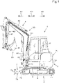
- FIG. 1 is a side view of a working machine 1 according to the present embodiment.
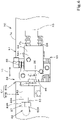
- FIG. 2 is a schematic plan view of the working machine 1.
- a backhoe which is a swivel working machine, is described as an example of the working machine 1.
- the working machine 1 includes a traveling body 1A and a working device 4 attached to the traveling body 1A.
- the traveling body 1A includes a traveling device 3 and a machine body (swivel base) 2 mounted on the traveling device 3.
- a forward direction corresponds a forward direction of an operator sitting on the operator's seat 6 (the direction of an arrow A1 in FIG. 1 ), a backward direction corresponds to a backward direction of the operator (the direction of an arrow A2 in FIG. 1 ), a leftward direction corresponds to a leftward direction of the operator (the direction of an arrow B1 in FIG. 2 ), and a rightward direction corresponds to a rightward direction of the operator (the direction of an arrow B2 in FIG. 2 ).
- a machine-body-width direction K2 (the width direction of the machine body 2) corresponds to a horizontal direction perpendicular to the front-back direction K1.
- a machine-body-outward direction corresponds to a rightward direction or a leftward direction from a central part of the machine body 2 in the width direction. That is, the machine-body-outward direction is a direction away from the center of the machine body 2 in the machine-body-width direction K2.
- a machine-body-inward direction corresponds to a direction opposite to the machine-body-outward direction. That is, the machine-body-inward direction is a direction toward the center of the machine body 2 in the machine-body-width direction.
- the traveling device 3 is a device that supports the machine body 2 so that the machine body 2 is capable of traveling.
- the traveling device 3 is driven by a traveling motor 11 including a hydraulic motor (hydraulic actuator), an electric motor, or the like.
- the traveling device 3 of a crawler type is used.
- the type of the traveling device 3 is not limited to this, and a traveling device of a wheel type or the like may be used.
- a dozer 7 is mounted on a front part of the traveling device 3.
- the dozer 7 includes a blade 7A, a dozer arm (driven member) 7B that is fixed to a back part of the blade 7A, and a dozer cylinder (hydraulic cylinder) 7C that raises and lowers the dozer arm 7B.
- a back part of the dozer arm 7B is pivotably supported by a frame of the traveling device 3 so that the dozer arm 7B can be raised and lowered.
- the dozer cylinder 7C is provided so as to extend from an intermediate part of the dozer arm 7B to the frame of the traveling device 3, and can raise and lower the dozer arm 7B (the blade 7A) by extending and contracting.
- the dozer arm 7B is raised when the dozer cylinder 7C extends, and the dozer arm 7B is lowered when the dozer cylinder 7C contracts.
- the machine body 2 includes a swivel base plate 9 that is included in a bottom part thereof and that is made from a steel plate or the like.
- the swivel base plate 9 is supported on the traveling device 3 via a swivel bearing 8 so as to be capable of swiveling around a swivel axis X1 extending in the up-down direction.
- a weight 10 is provided in a back part of the machine body 2.
- a prime mover is mounted in a back part of the machine body 2.
- the prime mover is a diesel engine.
- the prime mover may be a gasoline engine, an electric motor, or a hybrid prime mover including an engine and an electric motor.
- the machine body 2 includes, in a front part thereof, a support bracket 20 and a swing bracket 21 that support the working device 4.
- the support bracket 20 protrudes in the forward direction from the machine body 2.
- the swing bracket 21 is attached to a front part of the support bracket 20 (a part protruding from the machine body 2) so as to be swingable around a vertical axis (an axis extending in the up-down direction).
- a base part (back part) of the swing bracket 21 is rotatable in a horizontal direction (the machine-body-width direction K2) around a swing axis X2 (see FIG. 2 ) extending in the up-down direction.
- the working device 4 includes a boom device 30, an arm device 40, and a working tool device 50.
- the boom device 30 includes a boom 31 and a boom cylinder 32.
- a base part of the boom 31 is swingably (rotatably) supported on an upper part of the swing bracket 21 via a horizontal shaft 35 extending in the machine-body-width direction K2.
- the boom cylinder 32 includes a hydraulic cylinder that is extendable and contractible, is provided so as to extend from the swing bracket 21 to an intermediate part of the boom 31, and swings the boom 31 by extending and contracting.
- the arm device 40 includes an arm 41 and an arm cylinder 42.
- a base end part of the arm 41 is swingably supported by a distal end part of the boom 31 via a horizontal shaft 43.
- the arm cylinder 42 includes a hydraulic cylinder that is extendable and contractible, is provided so as to extend from a base part of the arm 41 to an intermediate part of the boom 31, and swings the arm 41 by extending and contracting.
- the working tool device 50 includes a bucket 51 as a working tool and a bucket cylinder 52 as a working tool cylinder.
- the bucket 51 is swingably supported by a distal end part of the arm 41 via a pivot shaft 57.
- the bucket cylinder 52 includes an extendable and contractible hydraulic cylinder, is provided so as to extend from a link mechanism 53, which is provided the bucket 51 and a distal end part of the arm 41, to a base part of the arm 41, and swings the bucket 51 by extending and contracting.
- FIG. 3 is a perspective view illustrating a state in which a hold valve device 61 is mounted on the dozer cylinder 7C.
- the dozer cylinder 7C includes a cylinder tube 7a having a tubular shape and a piston rod 7b whose one end part is slidably inserted into the cylinder tube 7a.
- a bottom coupler 7c which is to be pivotably coupled to the dozer arm 7B, is provided on the bottom side of the cylinder tube 7a (a side from which the piston rod 7b does not protrude).
- a rod coupler 7d which is to be pivotably coupled to the frame of the traveling device 3, is provided on a distal end part of the cylinder tube 7a.
- a first cylinder pipe (hydraulic pipe) 62 through which a hydraulic fluid is supplied to and discharged from the dozer cylinder 7C, is connected to the bottom side of the cylinder tube 7a.
- a second cylinder pipe (hydraulic pipe) 63 through which a hydraulic fluid is supplied to and discharged from the dozer cylinder 7C, is connected to the rod side of the cylinder tube 7a (a side from which the piston rod 7b protrudes).
- the first cylinder pipe 62 communicates with a bottom-side fluid chamber of the cylinder tube 7a
- the second cylinder pipe communicates with a rod-side fluid chamber of the cylinder tube 7a.
- the bottom-side fluid chamber and the rod-side fluid chamber are partitioned by a piston that is accommodated in the cylinder tube 7a so as to be movable in a direction along the axis (the axial direction) of the cylinder tube 7a.
- the dozer cylinder 7C When a hydraulic fluid is supplied from the first cylinder pipe 62 to the bottom-side fluid chamber, the dozer cylinder 7C extends and a hydraulic fluid is discharged from the second cylinder pipe 63. When a hydraulic fluid is supplied from the second cylinder pipe 63 to the rod-side fluid chamber, the dozer cylinder 7C contracts and a hydraulic fluid is discharged the first cylinder pipe 62.
- the first cylinder pipe 62 is fixed to a front part of a side surface (left side surface) the cylinder tube 7a.
- the hold valve device 61 includes a hold valve (mount valve) 64.
- the hold valve 64 is a valve that allows or prohibits flow of a hydraulic fluid discharged from the first cylinder pipe 62.
- the hold valve 64 is provided in a hydraulic pipe passage between a dozer control valve, which switches the direction of a hydraulic fluid with respect to the dozer cylinder 7C, and the first cylinder pipe 62. If a pipe passage between the hold valve 64 and the dozer control valve breaks and the hydraulic fluid leaks, the hold valve 64 blocks the pipe passage to stop discharging of the hydraulic fluid from the first cylinder pipe 62.
- the hold valve 64 is disposed on a side (the left side) of the cylinder tube 7a and behind the first cylinder pipe 62.
- the hold valve 64 includes a valve body 64A having a rectangular block-like shape (rectangular-parallelepiped shape).
- the valve body 64A is disposed so that one end surface thereof in the thickness direction faces a side surface (left side surface) of the cylinder tube 7a.
- a drain port DR and a pilot port PL are formed in a back surface of the valve body 64A, an inlet port 65 is formed in a front part of an upper surface of the valve body 64A, and a cylinder port 66 is formed in a front surface of the valve body 64A.
- the drain port DR communicates with a hydraulic fluid tank that stores a hydraulic fluid. That is, the drain port DR is a port through which a hydraulic fluid is returned to the hydraulic fluid tank.
- the pilot port PL is a port through which a pilot signal pressure is introduced. To be specific, a pilot signal pressure when a pilot valve that pilot-operates the dozer control valve is operated is introduced to the pilot port PL. A hydraulic fluid that has been output from the hydraulic pump and passed through the dozer control valve is introduced to the inlet port 65.
- the cylinder port 66 communicates with the first cylinder pipe 62, and allows a hydraulic fluid to flow therethrough so as to supply the hydraulic fluid to the first cylinder pipe 62. When a hydraulic fluid is discharged from the first cylinder pipe 62, the discharged hydraulic fluid flows into the cylinder port 66.
- a shut-off valve and a switching valve are provided in the valve body 64A.
- the switching valve is switched to one position to cause the shut-off valve to be in a pass-allowing state in which a hydraulic fluid can pass therethrough.
- a hydraulic fluid introduced to the inlet port 65 can be supplied from the cylinder port 66 to the first cylinder pipe 62, and, when a hydraulic fluid is discharged the first cylinder pipe 62, the hydraulic fluid can flow from the cylinder port 66 to the drain port DR.
- the switching valve When the pilot signal pressure is not introduced to the pilot port PL, the switching valve is switched to the other position to cause the shut-off valve to be in a shut-off state in which a hydraulic fluid cannot flow therethrough. Then, a hydraulic fluid discharged from the first cylinder pipe 62 does not flow from the cylinder port 66 to the drain port DR.
- the hold valve device 61 includes an adjustment mechanism 67.
- the adjustment mechanism 67 adjusts the positions of a pipe fastening portion 87, where the first cylinder pipe 62 is fastened to the cylinder port 66, and the hold valve 64.
- the adjustment mechanism 67 includes an attachment structure 67A that attaches the hold valve 64 to the cylinder tube 7a (the dozer cylinder 7C), and a connection structure 67B that connects the cylinder port 66 and the first cylinder pipe 62.
- the hold valve device 61 includes a valve mounting mechanism that mounts the hold valve (mount valve) 64 on the cylinder tube 7a of the dozer cylinder 7C (hydraulic cylinder); and the valve mounting mechanism includes the attachment structure 67A, the connection structure 67B, and the adjustment mechanism 67.
- the dozer cylinder 7C (hydraulic cylinder) and the hold valve (mount valve) 64, which is mounted on the cylinder tube 7a of the dozer cylinder 7C by using the valve mounting mechanism, are included in a hydraulic device.
- the attachment structure 67A includes a clamp member 68 and an attachment body 69.
- the clamp member 68 includes a pair of components (a first component 68A and a second component 68B).
- the first component 68A includes a curved (semicylindrical) fitting portion 71A that fits to the cylinder tube 7a from the outside in the radial direction, and a pair of fixing pieces 72A and 72B that extend in the radial direction from both ends in the circumferential direction of the fitting portion 71A.
- the second component 68B includes a fitting portion 71B and a pair of fixing pieces 73A and 73B.
- the clamp member 68 is attached to the cylinder tube 7a by fastening the facing fixing pieces to each other (the fixing piece 72A and the fixing piece 73A to each other, and the fixing piece 72B and the fixing piece 73B to each other) by using bolts 74 and nuts 75. Accordingly, by loosening the bolts 74 and the nuts 75, the position of the clamp member 68 is adjustable in a first direction (the arrow Y1 direction in FIG. 4 ) along the axis X3 direction of the cylinder tube 7a and a second direction (the arrow Y2 direction in FIG. 5 ) along the circumferential direction R1 of the cylinder tube 7a.
- the attachment body 69 is provided between the clamp member 68 and the hold valve 64.
- the attachment body 69 includes an attachment base 76 and an attachment plate 77.
- the attachment base 76 includes a pair of fixing members 76A and 76B that are welded to the clamp member 68 (one of the components) and a base plate 76C that is welded to the pair of fixing members 76A and 76B.
- the fixing member 76A and the fixing member 76B are disposed so as to be spaced apart in the longitudinal direction of the cylinder tube 7a.
- a part of each of the fixing member 76A and the fixing member 76B on a side fixed to the cylinder tube 7a has a curved shape that coincides with the curved shape of the fitting portion of the clamp member 68.
- the attachment plate 77 is disposed on a side of the fixing member 76A and the fixing member 76B opposite to the cylinder tube 7a, is provided so as to extend from the fixing member 76A to the fixing member 76B, and is welded to the pair of fixing members 76A and 76B.
- a plurality of (in the present embodiment, two) screw holes 78 are formed in the base plate 76C.
- the screw holes 78 each have a female thread in an inner periphery thereof.
- the screw holes 78 are formed in an upper part and a lower part of the attachment plate 77.
- the attachment plate 77 is superposed on a surface (an attachment surface 76a) of the base plate 76C opposite to the cylinder tube 7a, and is attached to the base plate 76C (the attachment surface 76a) by using attachment bolts 79.
- Bolt insertion holes 80 through which the attachment bolts 79 are inserted, are formed in the attachment plate 77.
- the bolt insertion holes 80 are elongated holes that are elongated in a direction (third direction Y3) parallel to a direction perpendicular to the axis X4 of a first pipe fitting 83 described below.
- the attachment plate 77 is attached the base plate 76C by inserting the attachment bolts 79 through the bolt insertion holes 80 and screwing the attachment bolts 79 into the screw holes 78.
- the position of the attachment plate 77 is adjustable with respect to the base plate 76C within the range of the elongated holes of the bolt insertion holes 80.
- a plurality of (in the present embodiment, two) nut portions 81 are provided on the attachment plate 77.
- the hold valve 64 is attached to the attachment plate 77 by using attachment bolts 82 that extend through the valve body 64A and are screwed into the nut portions 81.
- the connection structure 67B includes the first pipe fitting 83, a second pipe fitting 84, and an intermediate-connection member 85.
- a first end part of the first pipe fitting 83 is rotatably connected to the first cylinder pipe 62.
- a second end part of the first pipe fitting 83 is connected to the intermediate-connection member 85.
- a first end part of the second pipe fitting 84 is connected to the cylinder port 66.
- a second end part of the second pipe fitting 84 is connected to the intermediate-connection member 85.
- the first pipe fitting 83 includes a connection pipe 83A and an adapter nut 83B.
- One end of the connection pipe 83A is fixed to the intermediate-connection member 85.
- the connection pipe 83A includes, at the other end thereof, a connection portion 83Aa that is taper-fitted into a connection portion (first joint portion) 62A of the first cylinder pipe 62.
- the adapter nut 83B is screw-fitted onto the first joint portion 62A.
- the connection portion 83Aa and the adapter nut 83B are included in a second joint portion 86 that is fastened to the first joint portion 62A.
- the first joint portion 62A and the second joint portion 86 are included in the pipe fastening portion 87 where the first cylinder pipe 62 (hydraulic pipe) is fastened to the cylinder port 66.
- the first joint portion 62A, the second joint portion 86 (the first pipe fitting 83), and the pipe fastening portion 87 have the same axis X4.
- the second pipe fitting 84 includes a first adapter 84A that is connected to the cylinder port 66, a second adapter 84B that is connected to the intermediate-connection member 85, and a coupling 84C that joins the first adapter 84A and the second adapter 84B.
- the intermediate-connection member 85 is a rectangular-block-shaped member in which a connection fluid passage 88 that connects the first pipe fitting 83 and the second pipe fitting 84 is formed.
- the connection fluid passage 88 includes a first fluid passage 88a whose axis is the same as the axis X4 of the first pipe fitting 83, a second fluid passage 88b whose axis is the same as the axis X5 of the second pipe fitting 84, a third fluid passage 88c that is formed in a direction perpendicular to the axes X4 and X5 and that connects the first fluid passage 88a and the second fluid passage 88b.
- the third fluid passage 88c is formed from one end part of the intermediate-connection member 85 and is blocked by a plug 85A.
- the axis X4 of the first pipe fitting 83 and the axis X5 of the second pipe fitting 84 extend parallel to the axis X3 of the cylinder tube 7a.
- the axis X4 of the first pipe fitting 83 and the axis X5 of the second pipe fitting 84 are offset from each other (so as to be parallel to each other) by a predetermined distance in a direction perpendicular to these axial directions.
- the attachment surface 76a is a surface that is parallel to (orthogonal to a direction perpendicular to) the axis X3 of the cylinder tube 7a.
- the bolt insertion holes 80 are elongated holes that are elongated in a direction (third direction Y3) that is along the attachment surface 76a and that is parallel to a direction perpendicular to the axis X4 of the first pipe fitting 83. Accordingly, the position of the attachment plate 77 is adjustable along the attachment surface 76a in the third direction (adjustment direction) Y3 that is parallel to the direction perpendicular to the axial direction of the first pipe fitting 83.
- the axis-to-axis distance L1 between the first pipe fitting 83 and the second pipe fitting 84 increases and decreases when the first pipe fitting 83 rotates in a fourth direction Y4 around the axis thereof.
- a fifth direction Y5 that is a direction in which the hold valve 64 moves closer to and away from the cylinder tube 7a.
- the position of the hold valve 64 is adjustable with respect to the pipe fastening portion 87 in the first direction Y1, the second direction Y2, the third direction Y3, and the fifth direction Y5.
- It is possible to adjust the position of the hold valve 64 in the fifth direction by rotating the connection structure 67B in the fourth direction Y4.
- FIGS. 9 and 10 illustrate the attachment base 76 according to a modification.
- a fixing member 76D and a fixing member 76E are disposed so as to extend in a direction along the axial direction of the clamp member 68 (the axial direction of the cylinder tube 7a), are disposed so as to be spaced apart in the circumferential direction of the clamp member 68 (the circumferential direction R1 of the cylinder tube 7a), and are welded to the clamp member 68.
- Cutout portions 76F are formed in the base plate 76C by cutting out parts of the base plate 76C between the fixing member 76D and the fixing member 76E.
- FIGS. 11 and 12 illustrate an example in which a cover member 89, which covers the hold valve device 61 and the cylinder tube 7a, is provided in the dozer cylinder 7C.
- the cover member 89 includes an upper wall portion 89A that covers the upper side of the cylinder tube 7a, a first side-wall portion 89B that is disposed on one side (the left side) of the cylinder tube 7a and covers the one side of the hold valve 64, and a second side-wall portion 89C that covers the other side of the cylinder tube 7a.
- a first boss 91A to which the upper wall portion 89A is attached by using a bolt 90A, a second boss 91B to which the first side-wall portion 89B is attached by using a bolt 90B, and a third boss 91C to which the second side-wall portion 89C is attached by using a bolt 90C are fixed to the cylinder tube 7a.
- the first side-wall portion 89B includes a first section 89Ba on the upper side thereof and a second section 89Bb on the lower side thereof.
- the first section 89Ba is inclined in a direction such that the distance between a part of the first section 89Ba and the cylinder tube 7a increases as the part shifts downward from an end, in the machine-body-width direction K2, of the upper wall portion 89A.
- the second section 89Bb extends downward from a lower end of the first section 89Ba while maintaining a predetermined distance from the hold valve 64.
- a stay member 92 is fixed to the inside of the first section 89Ba, and the stay member 92 is attached to the second boss 91B.
- An open hole 93 for performing an operation of fastening the bolt 90B to attach the stay member 92 to the second boss 91B, is formed in the upper wall portion 89A.
- the stay member 92 is fixed also to the inside of the upper wall portion 89A.
- the second side-wall portion 89C is inclined in a direction such the distance between a part of second side-wall portion 89C and the cylinder tube 7a increases as the part shifts downward from an end, in the machine-body-width direction K2, of the upper wall portion 89A.
- FIG. 13 is a sectional view illustrating another configuration of the cover member 89.
- the first side-wall portion 89B of the cover member 89 is formed in such a shape that the second section 89Bb is extended in the inclination direction of the first section 89Ba.
- the hold valve 64 is attached along the inclination of the first side-wall portion 89B.
- the open hole 93 is formed from the upper wall portion 89A to an upper part of the first side-wall portion 89B.
- the cover member 89 includes a lower plate 89D that protrudes from a lower part of the second section 89Bb toward a position below the cylinder tube 7a and that covers the cylinder tube 7a and the hold valve device 61 from below.
- FIGS. 14 , 15 , and 16 illustrate an embodiment according to a modification of the adjustment mechanism 67.
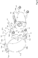
- FIG. 14 is a bottom perspective view of the dozer cylinder 7C and the hold valve device 61.
- FIG. 15 is a front partial sectional view of the dozer cylinder 7C and the hold valve device 61 in a state in which the cover member 89 is mounted.
- FIG. 16 is an enlarged view illustrating a state in which the lower side of the hold valve device 61 faces upward. Accordingly, the upward direction in FIG. 16 corresponds to the downward direction from the hold valve device 61.
- the modification illustrated in FIGS. 14 to 16 differs from the embodiment described above in that the adjustment mechanism 67 does not have the connection structure 67B although having the attachment structure 67A and in that the configuration of the attachment structure 67A differs from that in the embodiment.
- the cylinder port 66 of the hold valve 64 is connected to the first cylinder pipe 62 via a pipe fitting (connection structure) 94 having a linear shape.
- the first cylinder pipe 62 includes a base part pipe 62C and a connection pipe 62B.
- the base part pipe 62C is an elbow pipe.
- the connection pipe 62B includes a connection portion 95A that is connected to the elbow pipe, a first joint portion 95B that is fastened to the second joint portion 86 of the pipe fitting 94, and a pipe portion 95C between the connection portion 95A and the first joint portion 95B.
- the pipe portion 95C is formed so that the axis thereof on the elbow pipe side and the axis thereof on the second joint portion 86 side are offset parallelly.
- the attachment structure 67A includes the clamp member 68 that is attached to the cylinder tube 7a and the attachment body 69 to which the hold valve 64 is attached.
- the clamp member 68 is configured in the same way as that of the embodiment described above. Accordingly, the position of the hold valve 64 is adjustable in the first direction Y1 by sliding the clamp member 68 in the axial direction of the cylinder tube 7a, and the position of the hold valve 64 is adjustable in the second direction Y2 by rotating the clamp member 68 in the circumferential direction R1 of the cylinder tube 7a.
- the attachment body 69 includes a first bracket 96, a second bracket 97, a plate member 98, a first attachment piece 99, and a second attachment piece 100.
- the first bracket 96 is welded to the clamp member 68.
- the second bracket 97 is attached to a cylinder boss 101, which is welded to the cylinder tube 7a, by using a bolt (first bolt) 102A.
- the second bracket 97 is formed by bending a plate material into an L-shape, and includes a first attachment portion 97a and a second attachment portion 97b that is perpendicular to the first attachment portion 97a.
- the first attachment portion 97a is attached to the cylinder boss 101.
- the plate member 98 is disposed on the lower side of the hold valve 64.
- the hold valve 64 is attached to the plate member 98 by using a bolt that extends through the valve body 64A and that is screwed into a screw hole formed in the plate member 98.
- the first attachment piece 99 and the second attachment piece 100 are fixed to a surface (lower surface) of the plate member 98 opposite to the hold valve 64.
- the first attachment piece 99 is superposed on the first bracket 96 and attached to the first bracket 96 by using a bolt (second bolt) 102B and a nut 108B.
- the second attachment piece 100 is superposed on the second attachment portion 97b of the second bracket 97 and attached to the second attachment portion 97b by using a bolt (third bolt) 102C and a nut 108C.
- the first attachment piece 99 is attached to the first bracket 96 so that the position of the first attachment piece 99 is adjustable in two directions (one direction Y6, the other direction Y7) that are perpendicular to the axis X4 of the pipe fastening portion 87 and that are perpendicular to each other.
- the first bracket 96 has a bolt insertion hole through which a second bolt 102B is inserted and that is an elongated hole that is elongated in an eighth direction Y8 parallel to the one direction Y6;
- the first attachment piece 99 has a bolt insertion hole through which a second bolt 102B is inserted and that is an elongated hole that is elongated in a ninth direction Y9 parallel to the other direction; and the position of the first attachment piece 99 is adjustable in the eighth direction Y8 and the ninth direction Y9.
- the second attachment piece 100 is attached to the second bracket 97 so that the position of the second attachment piece 100 is adjustable in a direction parallel to the one direction Y6.
- the second attachment portion 97b of the second bracket 97 has a bolt insertion hole through which a third bolt 102C is inserted and that is an elongated hole that is elongated in the eighth direction, and, thus, the position of the second attachment piece 100 is adjustable in the eighth direction.
- the second bracket 97 is attached to the cylinder boss 101 so that the position of the second bracket 97 is adjustable in a direction parallel to the other direction Y7.
- the first attachment portion 97a of the second bracket 97 has a bolt insertion hole through which a first bolt 102A is inserted and that is an elongated hole that is elongated in the ninth direction Y9, and, thus, the position of the second bracket 97 is adjustable in the ninth direction Y9.
- the cover member 89 includes: the upper wall portion 89A; the first side-wall portion 89B, which extends from an end part (left end part) of the upper wall portion 89A in the downward direction perpendicular to the upper wall portion 89A; the second side-wall portion 89C, which extends from the other end part (right end part) of the upper wall portion 89A in an inclination direction such that the second side-wall portion 89C shifts rightward in the downward direction; and the lower plate 89D, which extends from the first side-wall portion 89B toward the cylinder tube 7a.
- Members and portions that are the same as those of the embodiment described above will be denoted by the same reference numerals, and descriptions of such members and portions will be omitted.
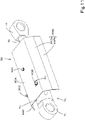
- FIG. 17 illustrates an adjustment mechanism 67 according to another modification.
- the adjustment mechanism 67 includes the clamp member 68, a pair of block members 103A and 103B that are attached to the clamp member 68, a holding frame (holding member) 104 that is attached to one of the block members (a first block member 103A) and the other block member (a second block member 103B) and to which the hold valve 64 is attached.
- the clamp member 68 is configured in the same way as that of the embodiment described above. Accordingly, the position of the hold valve 64 is adjustable in the first direction Y1 by moving the clamp member 68 in a direction along the axial direction of the cylinder tube 7a (see FIG. 4 ), and the position of the hold valve 64 is adjustable in the second direction Y2 by rotating the clamp member 68 in the circumferential direction R1 of the cylinder tube 7a.
- the first block member 103A is attached by being interposed between the fixing piece 72A at a first end part of the first component 68A and the fixing piece 73A at a first end part of the second component 68B.
- the first block member 103A has a rectangular block-like shape, is disposed between the fixing piece 72A and the fixing piece 73A, and is attached by using a bolt 106A that extends through the fixing pieces 72A and 73A and the first block member 103A and that is screwed into a nut 105A fixed to the fixing piece 72A.
- the second block member 103B is attached by being interposed between the fixing piece 72B at a second end part of the first component 68A and the fixing piece 73B at a second end part of the second component 68B.
- the second block member 103B has a rectangular block-like shape, is disposed between the fixing piece 72B and the fixing piece 73B, and is attached by using a bolt 106B that extends through the fixing pieces 72B and 73B and the second block member 103B and that is screwed into a nut 105B fixed to the fixing piece 72B.
- the holding frame 104 is formed by bending a strip material and includes a first section 104A, a second section 104B, and a third section 104C.
- the first section 104A is superposed on a surface (an attachment surface 103Aa) of the first block member 103A opposite to the cylinder tube 7a and is attached by using a first bolt 107A.
- a bolt insertion hole through which the first bolt 107A is inserted is an elongated hole that is elongated in a direction (tenth direction Y10) that is along the attachment surface 103Aa of the first block member 103A and that is parallel to a direction perpendicular to the axis X4 of the pipe fastening portion 87.
- the second section 104B is superposed on a surface (an attachment surface 103Ba) of the second block member 103B opposite to the cylinder tube 7a and is attached by using a second bolt 107B.
- a bolt insertion hole through which the second bolt 107B is inserted is an elongated hole that is elongated in a direction (tenth direction Y10) that is along the attachment surface 103Ba of the second block member 103B and that is parallel to the direction perpendicular to the axis X4 of the pipe fastening portion 87.
- the third section 104C couples the first section 104A and the second section 104B.
- the third section 104C is bent in a V-shape at a bent portion 104a in an intermediate part thereof.
- the hold valve 64 is fixed, by using a bolt, to a part of the holding frame 104 between the bent portion 104a of the third section 104C and the first section 104A.
- the valve mounting mechanism described above for mounting a mount valve (the hold valve 64) on the cylinder tube 7a of a hydraulic cylinder (the dozer cylinder 7C), includes: the attachment structure 67A that attaches the mount valve 64 to the hydraulic cylinder 7C; the connection structure 67B that connects a second end part of the hydraulic pipe 62, whose first end part is connected to the hydraulic cylinder 7C, to the cylinder port 66 of the mount valve 64; and the adjustment mechanism 67 that adjusts relative positions of the pipe fastening portion 87, where the hydraulic pipe 62 is fastened to the connection structure 67B, and the mount valve 64.
- the connection structure 67B includes, as the adjustment mechanism 67, the first pipe fitting 83 whose first end part is rotatably fastened to the hydraulic pipe 62, the second pipe fitting 84 that is disposed at a position where the axial direction of the second pipe fitting 84 is parallel to the axial direction of the first pipe fitting 83 and where the second pipe fitting 84 is offset from the first pipe fitting 83 in a direction perpendicular to the axial directions and that has a first end part connected to the cylinder port 66, and the intermediate-connection member to which a second end part of the first pipe fitting 83 and a second end part of the second pipe fitting 84 are connected.
- the connection structure includes, as the adjustment mechanism 67, the clamp member 68 that is attached to the cylinder tube 7a of the hydraulic cylinder 7C so that the position of the clamp member 68 is adjustable in the circumferential direction R1, the attachment base 76 that is fixed to the clamp member 68, and the attachment plate 77 to which the mount valve 64 is to be attached.
- the axis X4 of the first pipe fitting 83 and the axis X5 of the second pipe fitting 84 extend in a direction parallel to the axis X3 of the cylinder tube 7a.
- the attachment base 76 has the attachment surface 76a to which the attachment plate 77 is attached so that the position of the attachment plate 77 is adjustable in an adjustment direction (the third direction Y3) parallel to a direction perpendicular to the axial direction of the first pipe fitting 83.
- the attachment surface 76a the attachment surface may be a surface that is orthogonal to a direction perpendicular to the axis X3 of the cylinder tube 7a, and the position of the attachment plate 77 may be adjustable along the attachment surface 76a in the adjustment direction.
- the connection structure includes, as the adjustment mechanism 67, the clamp member 68 that is attached to the cylinder tube 7a of the hydraulic cylinder 7C so that the position of the clamp member 68 is adjustable in the circumferential direction, the first bracket 96 that is fixed to the clamp member 68, the second bracket 97 that is attached to the cylinder boss 101 that is fixed to the cylinder tube 7a, and the attachment body 69 that is supported by the first bracket 96 and the second bracket 97 so that the position of the attachment body 69 is adjustable in a direction parallel to a direction perpendicular to the axis X4 of the pipe fastening portion 87 and to which the mount valve 64 is to be attached.
- the attachment body 69 includes the plate member 98 to which the mount valve 64 is to be attached, and the first attachment piece 99 and the second attachment piece 100 that are fixed to the plate member 98.
- the first attachment piece 99 is attached to the first bracket 96 so that the position of the first attachment piece 99 is adjustable in two directions parallel to two directions that are perpendicular to the axis of the pipe fastening portion 87 and that are perpendicular to each other.
- the second attachment piece 100 is attached to the second bracket 97 so that the position of the second attachment piece 100 is adjustable in one direction Y6 of the two directions.
- the second bracket 97 is attached to the cylinder boss 101 so that the position of the second bracket 97 is adjustable in the other direction Y7 of the two directions.
- the connection structure includes, as the adjustment mechanism 67, the clamp member 68 that is attached to the cylinder tube 7a of the hydraulic cylinder 7C so that the position of the clamp member 68 is adjustable in the circumferential direction, the pair of block members (one block members 103A, the other block member 103B) that are attached to the clamp member 68, and the holding member (the holding frame 104) that holds the mount valve 64.
- the clamp member 68 includes the pair of components (the first component 68A, the second component 68B) that are attached with the cylinder tube 7a interposed therebetween.
- the block member 103A is attached so as to be interposed between first end parts of the pair of components 68A and 68B.
- the block member 103B is attached so as to be interposed between second end parts of the pair of components 68A and 68B.
- the holding member 104 is provided so as to extend from the block member 103A to the block member 103B and is attached to the pair of block members 103A and 103B so that the position of the holding member 104 is adjustable in a direction parallel to a direction perpendicular to the axial direction of the pipe fastening portion 87.
- the mount valve 64 is a hold valve that switches between a state in which the hold valve allows passing of a hydraulic fluid discharged from the hydraulic pipe 62 and a state in which the hold valve prohibits passing of a hydraulic fluid discharged from the hydraulic pipe 62.
- the hydraulic device includes the hydraulic cylinder 7C and the mount valve 64 that is mounted on the cylinder tube 7a of the hydraulic cylinder 7C by using the valve mounting mechanism.
- the working machine 1 includes the hydraulic device.
Landscapes
- Engineering & Computer Science (AREA)
- General Engineering & Computer Science (AREA)
- Mining & Mineral Resources (AREA)
- Civil Engineering (AREA)
- Structural Engineering (AREA)
- Physics & Mathematics (AREA)
- Fluid Mechanics (AREA)
- Mechanical Engineering (AREA)
- Actuator (AREA)
- Component Parts Of Construction Machinery (AREA)
Abstract
Description
- The present invention relates to a valve mounting mechanism that mounts a mount valve on a hydraulic cylinder and to a hydraulic device and a working machine including the valve mounting mechanism.
- To date, a working machine disclosed in
PTL 1 is known. - The working machine disclosed in
PTL 1 includes a hydraulic cylinder that drives a driven member (boom). Hydraulic pipes, through which a hydraulic fluid is supplied to and discharged from the hydraulic cylinder, are connected to the hydraulic cylinder. A hold valve (fall prevention valve), which allows or prohibits passing of a hydraulic fluid discharged from the hydraulic pipe, is attached to the hydraulic cylinder. - PTL 1:
Japanese Unexamined Patent Application Publication No. 2001-295810 - In the working machine disclosed in
PTL 1, the hold valve has a cylinder port that is connected to the hydraulic pipe. If the hydraulic pipe is not precisely fastened to the cylinder port, an irregular force is applied to a pipe fastening portion where the hydraulic pipe is fastened to the cylinder port, and the risk of fluid leakage increases. - In consideration of the above problem, an object of the present invention is to suppress strain on a pipe fastening portion where a hydraulic pipe, which is connected to a hydraulic cylinder, is fastened to a cylinder port of a mount valve.
- A valve mounting mechanism according to an aspect of the present invention, which is a valve mounting mechanism for mounting a mount valve on a cylinder tube of a hydraulic cylinder, includes: an attachment structure that attaches the mount valve to the hydraulic cylinder; a connection structure that connects a second end part of a hydraulic pipe, whose first end part is connected to the hydraulic cylinder, to a cylinder port of the mount valve; and an adjustment mechanism that adjusts relative positions of a pipe fastening portion, where the hydraulic pipe is fastened to the connection structure, and the mount valve.
- The connection structure includes, as the adjustment mechanism, a first pipe fitting whose first end part is rotatably fastened to the hydraulic pipe, a second pipe fitting that is disposed at a position where an axial direction of the second pipe fitting is parallel to an axial direction of the first pipe fitting and where the second pipe fitting is offset from the first pipe fitting in a direction perpendicular to the axial directions and that has a first end part connected to the cylinder port, and an intermediate-connection member to which a second end part of the first pipe fitting and a second end part of the second pipe fitting are connected.
- The connection structure includes, as the adjustment mechanism, a clamp member that is attached to the cylinder tube of the hydraulic cylinder so that a position of the clamp member is adjustable in a circumferential direction, an attachment base that is fixed to the clamp member, and an attachment plate to which the mount valve is to be attached. An axis of the first pipe fitting and an axis of the second pipe fitting extend in a direction parallel to an axis of the cylinder tube. The attachment base has an attachment surface to which the attachment plate is attached so that a position of the attachment plate is adjustable in an adjustment direction parallel to a direction perpendicular to an axial direction of the first pipe fitting.
- The attachment surface is a surface that is orthogonal to a direction perpendicular to the axis of the cylinder tube. The position of the attachment plate is adjustable along the attachment surface in the adjustment direction.
- The connection structure includes, as the adjustment mechanism, a clamp member that is attached to the cylinder tube of the hydraulic cylinder so that a position of the clamp member is adjustable in a circumferential direction, a first bracket that is fixed to the clamp member, a second bracket that is attached to a cylinder boss that is fixed to the cylinder tube, and an attachment body that is supported by the first bracket and the second bracket so that a position of the attachment body is adjustable in a direction parallel to a direction perpendicular to an axis of the pipe fastening portion and to which the mount valve is to be attached.
- The attachment body includes a plate member to which the mount valve is to be attached, and a first attachment piece and a second attachment piece that are fixed to the plate member. The first attachment piece is attached to the first bracket so that a position of the first attachment piece is adjustable in two directions parallel to two directions that are perpendicular to the axis of the pipe fastening portion and that are perpendicular to each other. The second attachment piece is attached to the second bracket so that a position of the second attachment piece is adjustable in one direction of the two directions. The second bracket is attached to the cylinder boss so that a position of the second bracket is adjustable in the other direction of the two directions.
- The connection structure includes, as the adjustment mechanism, a clamp member that is attached to the cylinder tube of the hydraulic cylinder so that a position of the clamp member is adjustable in a circumferential direction, a pair of block members that are attached to the clamp member, and a holding member that holds the mount valve. The clamp member includes a pair of components that are attached with the cylinder tube interposed therebetween. One of the block members is attached so as to be interposed between first end parts of the pair of components. The other block member is attached so as to be interposed between second end parts of the pair of components. The holding member is provided so as to extend from the one of the block members to the other block member and is attached to the pair of block members so that a position of the holding member is adjustable in a direction parallel to a direction perpendicular to an axial direction of the pipe fastening portion.
- The mount valve is a hold valve that switches between a state in which the hold valve allows passing of a hydraulic fluid discharged from the hydraulic pipe and a state in which the hold valve prohibits passing of a hydraulic fluid discharged from the hydraulic pipe.
- A hydraulic device according to an aspect of the present invention includes a hydraulic cylinder and a mount valve that is mounted on a cylinder tube of the hydraulic cylinder by using the valve mounting mechanism.
- A working machine according to an aspect of the present invention includes the hydraulic device.
- With the configuration described above, it is possible to suppress strain on the pipe fastening portion and to reduce the risk of fluid leakage by adjusting the positions of the pipe fastening portion and the mount valve.
-
- [
FIG. 1] FIG. 1 is a side view of a working machine. - [
FIG. 2] FIG. 2 is a plan view of the working machine. - [
FIG. 3] FIG. 3 is a perspective view of a dozer cylinder and a hold valve. - [
FIG. 4] FIG. 4 is a side view illustrating a state in which the hold valve is attached to a hydraulic cylinder. - [
FIG. 5] FIG. 5 is a front view illustrating a state in which the hold valve is attached to the hydraulic cylinder. - [
FIG. 6] FIG. 6 is a perspective view of an attachment structure and the hold valve. - [
FIG. 7] FIG. 7 is an exploded perspective view of the attachment structure. - [
FIG. 8] FIG. 8 is a sectional view of a connection structure. - [
FIG. 9] FIG. 9 is a perspective view of an attachment base according to a modification. - [
FIG. 10] FIG. 10 is a front view of the attachment base according to the modification. - [
FIG. 11] FIG. 11 is a perspective view illustrating a state in which a cover member is mounted on the hydraulic cylinder. - [
FIG. 12] FIG. 12 is a sectional view illustrating the state in which the cover member is mounted on the hydraulic cylinder. - [
FIG. 13] FIG. 13 is a sectional view illustrating another configuration of the cover member. - [
FIG. 14] FIG. 14 is a perspective view of an adjustment mechanism according to a modification. - [
FIG. 15] FIG. 15 is a front partial sectional view illustrating a state in which the cover member is mounted on the hydraulic cylinder. - [
FIG. 16] FIG. 16 is a partial enlarged perspective view of an adjustment mechanism according to a modification. - [
FIG. 17] FIG. 17 is a front view of an adjustment mechanism according to another modification. - Hereafter, an embodiment of the present invention will be described with reference to the drawings.
-
FIG. 1 is a side view of aworking machine 1 according to the present embodiment.FIG. 2 is a schematic plan view of theworking machine 1. In the present embodiment, a backhoe, which is a swivel working machine, is described as an example of theworking machine 1. - As illustrated in
FIG. 1 , theworking machine 1 includes atraveling body 1A and a workingdevice 4 attached to thetraveling body 1A. Thetraveling body 1A includes atraveling device 3 and a machine body (swivel base) 2 mounted on thetraveling device 3. An operator'sseat 6, on which an operator sits, is mounted on themachine body 2. - In the present embodiment, a forward direction corresponds a forward direction of an operator sitting on the operator's seat 6 (the direction of an arrow A1 in
FIG. 1 ), a backward direction corresponds to a backward direction of the operator (the direction of an arrow A2 inFIG. 1 ), a leftward direction corresponds to a leftward direction of the operator (the direction of an arrow B1 inFIG. 2 ), and a rightward direction corresponds to a rightward direction of the operator (the direction of an arrow B2 inFIG. 2 ). A machine-body-width direction K2 (the width direction of the machine body 2) corresponds to a horizontal direction perpendicular to the front-back direction K1. A machine-body-outward direction (outward in the machine-body-width direction K2) corresponds to a rightward direction or a leftward direction from a central part of themachine body 2 in the width direction. That is, the machine-body-outward direction is a direction away from the center of themachine body 2 in the machine-body-width direction K2. A machine-body-inward direction (inward in the machine-body-width direction) corresponds to a direction opposite to the machine-body-outward direction. That is, the machine-body-inward direction is a direction toward the center of themachine body 2 in the machine-body-width direction. - As illustrated in
FIG. 1 , the travelingdevice 3 is a device that supports themachine body 2 so that themachine body 2 is capable of traveling. The travelingdevice 3 is driven by a travelingmotor 11 including a hydraulic motor (hydraulic actuator), an electric motor, or the like. In the present embodiment, the travelingdevice 3 of a crawler type is used. However, the type of the travelingdevice 3 is not limited to this, and a traveling device of a wheel type or the like may be used. - As illustrated in
FIGS. 1 and2 , adozer 7 is mounted on a front part of the travelingdevice 3. Thedozer 7 includes ablade 7A, a dozer arm (driven member) 7B that is fixed to a back part of theblade 7A, and a dozer cylinder (hydraulic cylinder) 7C that raises and lowers thedozer arm 7B. A back part of thedozer arm 7B is pivotably supported by a frame of the travelingdevice 3 so that thedozer arm 7B can be raised and lowered. Thedozer cylinder 7C is provided so as to extend from an intermediate part of thedozer arm 7B to the frame of the travelingdevice 3, and can raise and lower thedozer arm 7B (theblade 7A) by extending and contracting. To be specific, thedozer arm 7B is raised when thedozer cylinder 7C extends, and thedozer arm 7B is lowered when thedozer cylinder 7C contracts. - The
machine body 2 includes aswivel base plate 9 that is included in a bottom part thereof and that is made from a steel plate or the like. Theswivel base plate 9 is supported on the travelingdevice 3 via a swivel bearing 8 so as to be capable of swiveling around a swivel axis X1 extending in the up-down direction. Aweight 10 is provided in a back part of themachine body 2. A prime mover is mounted in a back part of themachine body 2. The prime mover is a diesel engine. The prime mover may be a gasoline engine, an electric motor, or a hybrid prime mover including an engine and an electric motor. - The
machine body 2 includes, in a front part thereof, asupport bracket 20 and aswing bracket 21 that support the workingdevice 4. Thesupport bracket 20 protrudes in the forward direction from themachine body 2. Theswing bracket 21 is attached to a front part of the support bracket 20 (a part protruding from the machine body 2) so as to be swingable around a vertical axis (an axis extending in the up-down direction). To be specific, a base part (back part) of theswing bracket 21 is rotatable in a horizontal direction (the machine-body-width direction K2) around a swing axis X2 (seeFIG. 2 ) extending in the up-down direction. - The working
device 4 includes aboom device 30, anarm device 40, and a workingtool device 50. Theboom device 30 includes aboom 31 and aboom cylinder 32. A base part of theboom 31 is swingably (rotatably) supported on an upper part of theswing bracket 21 via ahorizontal shaft 35 extending in the machine-body-width direction K2. Theboom cylinder 32 includes a hydraulic cylinder that is extendable and contractible, is provided so as to extend from theswing bracket 21 to an intermediate part of theboom 31, and swings theboom 31 by extending and contracting. - The
arm device 40 includes anarm 41 and anarm cylinder 42. A base end part of thearm 41 is swingably supported by a distal end part of theboom 31 via a horizontal shaft 43. Thearm cylinder 42 includes a hydraulic cylinder that is extendable and contractible, is provided so as to extend from a base part of thearm 41 to an intermediate part of theboom 31, and swings thearm 41 by extending and contracting. The workingtool device 50 includes abucket 51 as a working tool and abucket cylinder 52 as a working tool cylinder. Thebucket 51 is swingably supported by a distal end part of thearm 41 via a pivot shaft 57. Thebucket cylinder 52 includes an extendable and contractible hydraulic cylinder, is provided so as to extend from a link mechanism 53, which is provided thebucket 51 and a distal end part of thearm 41, to a base part of thearm 41, and swings thebucket 51 by extending and contracting. -
FIG. 3 is a perspective view illustrating a state in which ahold valve device 61 is mounted on thedozer cylinder 7C. - As illustrated in
FIG. 3 , thedozer cylinder 7C includes acylinder tube 7a having a tubular shape and apiston rod 7b whose one end part is slidably inserted into thecylinder tube 7a. Abottom coupler 7c, which is to be pivotably coupled to thedozer arm 7B, is provided on the bottom side of thecylinder tube 7a (a side from which thepiston rod 7b does not protrude). Arod coupler 7d, which is to be pivotably coupled to the frame of the travelingdevice 3, is provided on a distal end part of thecylinder tube 7a. A first cylinder pipe (hydraulic pipe) 62, through which a hydraulic fluid is supplied to and discharged from thedozer cylinder 7C, is connected to the bottom side of thecylinder tube 7a. A second cylinder pipe (hydraulic pipe) 63, through which a hydraulic fluid is supplied to and discharged from thedozer cylinder 7C, is connected to the rod side of thecylinder tube 7a (a side from which thepiston rod 7b protrudes). Thefirst cylinder pipe 62 communicates with a bottom-side fluid chamber of thecylinder tube 7a, and the second cylinder pipe communicates with a rod-side fluid chamber of thecylinder tube 7a. The bottom-side fluid chamber and the rod-side fluid chamber are partitioned by a piston that is accommodated in thecylinder tube 7a so as to be movable in a direction along the axis (the axial direction) of thecylinder tube 7a. - When a hydraulic fluid is supplied from the
first cylinder pipe 62 to the bottom-side fluid chamber, thedozer cylinder 7C extends and a hydraulic fluid is discharged from thesecond cylinder pipe 63. When a hydraulic fluid is supplied from thesecond cylinder pipe 63 to the rod-side fluid chamber, thedozer cylinder 7C contracts and a hydraulic fluid is discharged thefirst cylinder pipe 62. In the present embodiment, thefirst cylinder pipe 62 is fixed to a front part of a side surface (left side surface) thecylinder tube 7a. - As illustrated in
FIG. 3 , thehold valve device 61 includes a hold valve (mount valve) 64. Thehold valve 64 is a valve that allows or prohibits flow of a hydraulic fluid discharged from thefirst cylinder pipe 62. To be specific, thehold valve 64 is provided in a hydraulic pipe passage between a dozer control valve, which switches the direction of a hydraulic fluid with respect to thedozer cylinder 7C, and thefirst cylinder pipe 62. If a pipe passage between thehold valve 64 and the dozer control valve breaks and the hydraulic fluid leaks, thehold valve 64 blocks the pipe passage to stop discharging of the hydraulic fluid from thefirst cylinder pipe 62. - As illustrated in
FIGS. 3 and4 , thehold valve 64 is disposed on a side (the left side) of thecylinder tube 7a and behind thefirst cylinder pipe 62. Thehold valve 64 includes avalve body 64A having a rectangular block-like shape (rectangular-parallelepiped shape). Thevalve body 64A is disposed so that one end surface thereof in the thickness direction faces a side surface (left side surface) of thecylinder tube 7a. A drain port DR and a pilot port PL are formed in a back surface of thevalve body 64A, aninlet port 65 is formed in a front part of an upper surface of thevalve body 64A, and acylinder port 66 is formed in a front surface of thevalve body 64A. - The drain port DR communicates with a hydraulic fluid tank that stores a hydraulic fluid. That is, the drain port DR is a port through which a hydraulic fluid is returned to the hydraulic fluid tank. The pilot port PL is a port through which a pilot signal pressure is introduced. To be specific, a pilot signal pressure when a pilot valve that pilot-operates the dozer control valve is operated is introduced to the pilot port PL. A hydraulic fluid that has been output from the hydraulic pump and passed through the dozer control valve is introduced to the
inlet port 65. Thecylinder port 66 communicates with thefirst cylinder pipe 62, and allows a hydraulic fluid to flow therethrough so as to supply the hydraulic fluid to thefirst cylinder pipe 62. When a hydraulic fluid is discharged from thefirst cylinder pipe 62, the discharged hydraulic fluid flows into thecylinder port 66. - A shut-off valve and a switching valve are provided in the
valve body 64A. When a pilot signal pressure is introduced from the pilot port PL, the switching valve is switched to one position to cause the shut-off valve to be in a pass-allowing state in which a hydraulic fluid can pass therethrough. When the shut-off valve is in the pass-allowing state, a hydraulic fluid introduced to theinlet port 65 can be supplied from thecylinder port 66 to thefirst cylinder pipe 62, and, when a hydraulic fluid is discharged thefirst cylinder pipe 62, the hydraulic fluid can flow from thecylinder port 66 to the drain port DR. When the pilot signal pressure is not introduced to the pilot port PL, the switching valve is switched to the other position to cause the shut-off valve to be in a shut-off state in which a hydraulic fluid cannot flow therethrough. Then, a hydraulic fluid discharged from thefirst cylinder pipe 62 does not flow from thecylinder port 66 to the drain port DR. - As illustrated in
FIG. 3 , thehold valve device 61 includes anadjustment mechanism 67. Theadjustment mechanism 67 adjusts the positions of apipe fastening portion 87, where thefirst cylinder pipe 62 is fastened to thecylinder port 66, and thehold valve 64. Theadjustment mechanism 67 includes anattachment structure 67A that attaches thehold valve 64 to thecylinder tube 7a (thedozer cylinder 7C), and aconnection structure 67B that connects thecylinder port 66 and thefirst cylinder pipe 62. In other words, thehold valve device 61 includes a valve mounting mechanism that mounts the hold valve (mount valve) 64 on thecylinder tube 7a of thedozer cylinder 7C (hydraulic cylinder); and the valve mounting mechanism includes theattachment structure 67A, theconnection structure 67B, and theadjustment mechanism 67. Thedozer cylinder 7C (hydraulic cylinder) and the hold valve (mount valve) 64, which is mounted on thecylinder tube 7a of thedozer cylinder 7C by using the valve mounting mechanism, are included in a hydraulic device. - As illustrated in
FIGS. 6 and7 , theattachment structure 67A includes aclamp member 68 and anattachment body 69. Theclamp member 68 includes a pair of components (afirst component 68A and asecond component 68B). Thefirst component 68A includes a curved (semicylindrical)fitting portion 71A that fits to thecylinder tube 7a from the outside in the radial direction, and a pair of fixingpieces fitting portion 71A. Likewise, thesecond component 68B includes afitting portion 71B and a pair of fixingpieces - As illustrated in
FIG. 5 , when thefirst component 68A and thesecond component 68B are disposed with thecylinder tube 7a interposed therebetween, the fixingpieces first component 68A and the fixingpieces second component 68B face each other. Then, theclamp member 68 is attached to thecylinder tube 7a by fastening the facing fixing pieces to each other (the fixingpiece 72A and the fixingpiece 73A to each other, and the fixingpiece 72B and the fixingpiece 73B to each other) by usingbolts 74 and nuts 75. Accordingly, by loosening thebolts 74 and the nuts 75, the position of theclamp member 68 is adjustable in a first direction (the arrow Y1 direction inFIG. 4 ) along the axis X3 direction of thecylinder tube 7a and a second direction (the arrow Y2 direction inFIG. 5 ) along the circumferential direction R1 of thecylinder tube 7a. - As illustrated in
FIG. 5 , theattachment body 69 is provided between theclamp member 68 and thehold valve 64. Theattachment body 69 includes anattachment base 76 and anattachment plate 77. - As illustrated in
FIGS. 6 and7 , theattachment base 76 includes a pair of fixingmembers base plate 76C that is welded to the pair of fixingmembers member 76A and the fixingmember 76B are disposed so as to be spaced apart in the longitudinal direction of thecylinder tube 7a. A part of each of the fixingmember 76A and the fixingmember 76B on a side fixed to thecylinder tube 7a has a curved shape that coincides with the curved shape of the fitting portion of theclamp member 68. Theattachment plate 77 is disposed on a side of the fixingmember 76A and the fixingmember 76B opposite to thecylinder tube 7a, is provided so as to extend from the fixingmember 76A to the fixingmember 76B, and is welded to the pair of fixingmembers base plate 76C. The screw holes 78 each have a female thread in an inner periphery thereof. The screw holes 78 are formed in an upper part and a lower part of theattachment plate 77. - As illustrated in
FIGS. 6 and7 , theattachment plate 77 is superposed on a surface (anattachment surface 76a) of thebase plate 76C opposite to thecylinder tube 7a, and is attached to thebase plate 76C (theattachment surface 76a) by usingattachment bolts 79. Bolt insertion holes 80, through which theattachment bolts 79 are inserted, are formed in theattachment plate 77. The bolt insertion holes 80 are elongated holes that are elongated in a direction (third direction Y3) parallel to a direction perpendicular to the axis X4 of a first pipe fitting 83 described below. Theattachment plate 77 is attached thebase plate 76C by inserting theattachment bolts 79 through the bolt insertion holes 80 and screwing theattachment bolts 79 into the screw holes 78. The position of theattachment plate 77 is adjustable with respect to thebase plate 76C within the range of the elongated holes of the bolt insertion holes 80. - As illustrated in
FIG. 6 , a plurality of (in the present embodiment, two)nut portions 81 are provided on theattachment plate 77. Thehold valve 64 is attached to theattachment plate 77 by usingattachment bolts 82 that extend through thevalve body 64A and are screwed into thenut portions 81. - As illustrated in
FIGS. 3 and4 , theconnection structure 67B includes the first pipe fitting 83, a second pipe fitting 84, and an intermediate-connection member 85. A first end part of the first pipe fitting 83 is rotatably connected to thefirst cylinder pipe 62. A second end part of the first pipe fitting 83 is connected to the intermediate-connection member 85. A first end part of the second pipe fitting 84 is connected to thecylinder port 66. A second end part of the second pipe fitting 84 is connected to the intermediate-connection member 85. - As illustrated in
FIG. 8 , the first pipe fitting 83 includes aconnection pipe 83A and anadapter nut 83B. One end of theconnection pipe 83A is fixed to the intermediate-connection member 85. Theconnection pipe 83A includes, at the other end thereof, a connection portion 83Aa that is taper-fitted into a connection portion (first joint portion) 62A of thefirst cylinder pipe 62. Theadapter nut 83B is screw-fitted onto the firstjoint portion 62A. The connection portion 83Aa and theadapter nut 83B are included in a secondjoint portion 86 that is fastened to the firstjoint portion 62A. The firstjoint portion 62A and the secondjoint portion 86 are included in thepipe fastening portion 87 where the first cylinder pipe 62 (hydraulic pipe) is fastened to thecylinder port 66. The firstjoint portion 62A, the second joint portion 86 (the first pipe fitting 83), and thepipe fastening portion 87 have the same axis X4. - The second pipe fitting 84 includes a
first adapter 84A that is connected to thecylinder port 66, asecond adapter 84B that is connected to the intermediate-connection member 85, and acoupling 84C that joins thefirst adapter 84A and thesecond adapter 84B. - The intermediate-
connection member 85 is a rectangular-block-shaped member in which aconnection fluid passage 88 that connects the first pipe fitting 83 and the second pipe fitting 84 is formed. Theconnection fluid passage 88 includes afirst fluid passage 88a whose axis is the same as the axis X4 of the first pipe fitting 83, asecond fluid passage 88b whose axis is the same as the axis X5 of the second pipe fitting 84, athird fluid passage 88c that is formed in a direction perpendicular to the axes X4 and X5 and that connects thefirst fluid passage 88a and thesecond fluid passage 88b. Thethird fluid passage 88c is formed from one end part of the intermediate-connection member 85 and is blocked by aplug 85A. - As illustrated in
FIG. 5 , the axis X4 of the first pipe fitting 83 and the axis X5 of the second pipe fitting 84 extend parallel to the axis X3 of thecylinder tube 7a. As illustrated inFIGS. 5 and8 , the axis X4 of the first pipe fitting 83 and the axis X5 of the second pipe fitting 84 are offset from each other (so as to be parallel to each other) by a predetermined distance in a direction perpendicular to these axial directions. - As illustrated in
FIG. 5 , in the present embodiment, theattachment surface 76a is a surface that is parallel to (orthogonal to a direction perpendicular to) the axis X3 of thecylinder tube 7a. The bolt insertion holes 80 are elongated holes that are elongated in a direction (third direction Y3) that is along theattachment surface 76a and that is parallel to a direction perpendicular to the axis X4 of the first pipe fitting 83. Accordingly, the position of theattachment plate 77 is adjustable along theattachment surface 76a in the third direction (adjustment direction) Y3 that is parallel to the direction perpendicular to the axial direction of the first pipe fitting 83. - As illustrated in
FIG. 5 , with the structure of theconnection structure 67B, the axis-to-axis distance L1 between the first pipe fitting 83 and the second pipe fitting 84 increases and decreases when the first pipe fitting 83 rotates in a fourth direction Y4 around the axis thereof. Thus, it is possible to adjust the position of thehold valve 64 in a fifth direction Y5 that is a direction in which thehold valve 64 moves closer to and away from thecylinder tube 7a. Moreover, by connecting thefirst cylinder pipe 62 and thecylinder port 66 via the first pipe fitting 83, the second pipe fitting 84, and the intermediate-connection member 85, even when the axis-to-axis distance L2 between the first pipe fitting 83 and the second pipe fitting 84 is small, it is possible to easily configure a piping structure between thecylinder port 66 and thefirst cylinder pipe 62. - As heretofore described, with the
adjustment mechanism 67, the position of thehold valve 64 is adjustable with respect to thepipe fastening portion 87 in the first direction Y1, the second direction Y2, the third direction Y3, and the fifth direction Y5. To be specific, it is possible to adjust the position of thehold valve 64 in the first direction Y1 by sliding theclamp member 68 in the axial direction of thecylinder tube 7a. It is possible to adjust the position of thehold valve 64 in the second direction Y2 by rotating theclamp member 68 in the circumferential direction R1 of thecylinder tube 7a. It is possible to adjust the position of thehold valve 64 in the third direction Y3 by sliding theattachment plate 77 in the third direction Y3 with respect to thebase plate 76C. It is possible to adjust the position of thehold valve 64 in the fifth direction by rotating theconnection structure 67B in the fourth direction Y4. - By performing these adjustments, it is possible to suppress occurrence of strain on the
pipe fastening portion 87 and to reduce the risk of fluid leakage. -
FIGS. 9 and10 illustrate theattachment base 76 according to a modification. In theattachment base 76 according to the modification, a fixingmember 76D and a fixingmember 76E are disposed so as to extend in a direction along the axial direction of the clamp member 68 (the axial direction of thecylinder tube 7a), are disposed so as to be spaced apart in the circumferential direction of the clamp member 68 (the circumferential direction R1 of thecylinder tube 7a), and are welded to theclamp member 68.Cutout portions 76F are formed in thebase plate 76C by cutting out parts of thebase plate 76C between the fixingmember 76D and the fixingmember 76E. Thus, it is possible to reduce an assembly stress due to decrease of the rigidity of theclamp member 68. -
FIGS. 11 and12 illustrate an example in which acover member 89, which covers thehold valve device 61 and thecylinder tube 7a, is provided in thedozer cylinder 7C. - The
cover member 89 includes anupper wall portion 89A that covers the upper side of thecylinder tube 7a, a first side-wall portion 89B that is disposed on one side (the left side) of thecylinder tube 7a and covers the one side of thehold valve 64, and a second side-wall portion 89C that covers the other side of thecylinder tube 7a. Afirst boss 91A to which theupper wall portion 89A is attached by using abolt 90A, asecond boss 91B to which the first side-wall portion 89B is attached by using abolt 90B, and athird boss 91C to which the second side-wall portion 89C is attached by using abolt 90C are fixed to thecylinder tube 7a. - The first side-
wall portion 89B includes a first section 89Ba on the upper side thereof and a second section 89Bb on the lower side thereof. The first section 89Ba is inclined in a direction such that the distance between a part of the first section 89Ba and thecylinder tube 7a increases as the part shifts downward from an end, in the machine-body-width direction K2, of theupper wall portion 89A. The second section 89Bb extends downward from a lower end of the first section 89Ba while maintaining a predetermined distance from thehold valve 64. Astay member 92 is fixed to the inside of the first section 89Ba, and thestay member 92 is attached to thesecond boss 91B. Anopen hole 93, for performing an operation of fastening thebolt 90B to attach thestay member 92 to thesecond boss 91B, is formed in theupper wall portion 89A. Thestay member 92 is fixed also to the inside of theupper wall portion 89A. The second side-wall portion 89C is inclined in a direction such the distance between a part of second side-wall portion 89C and thecylinder tube 7a increases as the part shifts downward from an end, in the machine-body-width direction K2, of theupper wall portion 89A. -
FIG. 13 is a sectional view illustrating another configuration of thecover member 89. - As illustrated in
FIG. 13 , the first side-wall portion 89B of thecover member 89 is formed in such a shape that the second section 89Bb is extended in the inclination direction of the first section 89Ba. Thehold valve 64 is attached along the inclination of the first side-wall portion 89B. Theopen hole 93 is formed from theupper wall portion 89A to an upper part of the first side-wall portion 89B. Thecover member 89 includes alower plate 89D that protrudes from a lower part of the second section 89Bb toward a position below thecylinder tube 7a and that covers thecylinder tube 7a and thehold valve device 61 from below. -
FIGS. 14 ,15 , and16 illustrate an embodiment according to a modification of theadjustment mechanism 67. -
FIG. 14 is a bottom perspective view of thedozer cylinder 7C and thehold valve device 61.FIG. 15 is a front partial sectional view of thedozer cylinder 7C and thehold valve device 61 in a state in which thecover member 89 is mounted.FIG. 16 is an enlarged view illustrating a state in which the lower side of thehold valve device 61 faces upward. Accordingly, the upward direction inFIG. 16 corresponds to the downward direction from thehold valve device 61. The modification illustrated inFIGS. 14 to 16 differs from the embodiment described above in that theadjustment mechanism 67 does not have theconnection structure 67B although having theattachment structure 67A and in that the configuration of theattachment structure 67A differs from that in the embodiment. - As illustrated in
FIGS. 14 and16 , thecylinder port 66 of thehold valve 64 is connected to thefirst cylinder pipe 62 via a pipe fitting (connection structure) 94 having a linear shape. Thefirst cylinder pipe 62 includes abase part pipe 62C and aconnection pipe 62B. Thebase part pipe 62C is an elbow pipe. Theconnection pipe 62B includes aconnection portion 95A that is connected to the elbow pipe, a firstjoint portion 95B that is fastened to the secondjoint portion 86 of the pipe fitting 94, and apipe portion 95C between theconnection portion 95A and the firstjoint portion 95B. Thepipe portion 95C is formed so that the axis thereof on the elbow pipe side and the axis thereof on the secondjoint portion 86 side are offset parallelly. - The
attachment structure 67A includes theclamp member 68 that is attached to thecylinder tube 7a and theattachment body 69 to which thehold valve 64 is attached. - As illustrated in
FIG. 16 , theclamp member 68 is configured in the same way as that of the embodiment described above. Accordingly, the position of thehold valve 64 is adjustable in the first direction Y1 by sliding theclamp member 68 in the axial direction of thecylinder tube 7a, and the position of thehold valve 64 is adjustable in the second direction Y2 by rotating theclamp member 68 in the circumferential direction R1 of thecylinder tube 7a. - As illustrated in
FIG. 16 , theattachment body 69 includes afirst bracket 96, asecond bracket 97, aplate member 98, afirst attachment piece 99, and asecond attachment piece 100. Thefirst bracket 96 is welded to theclamp member 68. Thesecond bracket 97 is attached to acylinder boss 101, which is welded to thecylinder tube 7a, by using a bolt (first bolt) 102A. To be specific, thesecond bracket 97 is formed by bending a plate material into an L-shape, and includes afirst attachment portion 97a and asecond attachment portion 97b that is perpendicular to thefirst attachment portion 97a. Thefirst attachment portion 97a is attached to thecylinder boss 101. - As illustrated in
FIG. 15 , theplate member 98 is disposed on the lower side of thehold valve 64. Thehold valve 64 is attached to theplate member 98 by using a bolt that extends through thevalve body 64A and that is screwed into a screw hole formed in theplate member 98. - As illustrated in
FIG. 16 , thefirst attachment piece 99 and thesecond attachment piece 100 are fixed to a surface (lower surface) of theplate member 98 opposite to thehold valve 64. Thefirst attachment piece 99 is superposed on thefirst bracket 96 and attached to thefirst bracket 96 by using a bolt (second bolt) 102B and anut 108B. Thesecond attachment piece 100 is superposed on thesecond attachment portion 97b of thesecond bracket 97 and attached to thesecond attachment portion 97b by using a bolt (third bolt) 102C and anut 108C. - As illustrated in
FIGS. 15 and16 , thefirst attachment piece 99 is attached to thefirst bracket 96 so that the position of thefirst attachment piece 99 is adjustable in two directions (one direction Y6, the other direction Y7) that are perpendicular to the axis X4 of thepipe fastening portion 87 and that are perpendicular to each other. To be specific, thefirst bracket 96 has a bolt insertion hole through which asecond bolt 102B is inserted and that is an elongated hole that is elongated in an eighth direction Y8 parallel to the one direction Y6; thefirst attachment piece 99 has a bolt insertion hole through which asecond bolt 102B is inserted and that is an elongated hole that is elongated in a ninth direction Y9 parallel to the other direction; and the position of thefirst attachment piece 99 is adjustable in the eighth direction Y8 and the ninth direction Y9. - The
second attachment piece 100 is attached to thesecond bracket 97 so that the position of thesecond attachment piece 100 is adjustable in a direction parallel to the one direction Y6. To be specific, thesecond attachment portion 97b of thesecond bracket 97 has a bolt insertion hole through which athird bolt 102C is inserted and that is an elongated hole that is elongated in the eighth direction, and, thus, the position of thesecond attachment piece 100 is adjustable in the eighth direction. - The
second bracket 97 is attached to thecylinder boss 101 so that the position of thesecond bracket 97 is adjustable in a direction parallel to the other direction Y7. To be specific, thefirst attachment portion 97a of thesecond bracket 97 has a bolt insertion hole through which afirst bolt 102A is inserted and that is an elongated hole that is elongated in the ninth direction Y9, and, thus, the position of thesecond bracket 97 is adjustable in the ninth direction Y9. - With the
adjustment mechanism 67 according to the modification described above, it is possible to suppress occurrence of strain on thepipe fastening portion 87 and to reduce the risk of fluid leakage by adjusting the position of theclamp member 68 in the first direction Y1 and the second direction Y2 and by adjusting the position of theattachment body 69 in the eighth direction Y8 and the ninth direction Y9. - As illustrated in
FIG. 15 , thecover member 89 according to the embodiment illustrated inFIGS. 14 to 16 includes: theupper wall portion 89A; the first side-wall portion 89B, which extends from an end part (left end part) of theupper wall portion 89A in the downward direction perpendicular to theupper wall portion 89A; the second side-wall portion 89C, which extends from the other end part (right end part) of theupper wall portion 89A in an inclination direction such that the second side-wall portion 89C shifts rightward in the downward direction; and thelower plate 89D, which extends from the first side-wall portion 89B toward thecylinder tube 7a. Members and portions that are the same as those of the embodiment described above will be denoted by the same reference numerals, and descriptions of such members and portions will be omitted. -
FIG. 17 illustrates anadjustment mechanism 67 according to another modification. - As illustrated in
FIG. 17 , theadjustment mechanism 67 according to the other modification includes theclamp member 68, a pair ofblock members clamp member 68, a holding frame (holding member) 104 that is attached to one of the block members (afirst block member 103A) and the other block member (asecond block member 103B) and to which thehold valve 64 is attached. - The
clamp member 68 is configured in the same way as that of the embodiment described above. Accordingly, the position of thehold valve 64 is adjustable in the first direction Y1 by moving theclamp member 68 in a direction along the axial direction of thecylinder tube 7a (seeFIG. 4 ), and the position of thehold valve 64 is adjustable in the second direction Y2 by rotating theclamp member 68 in the circumferential direction R1 of thecylinder tube 7a. - The
first block member 103A is attached by being interposed between the fixingpiece 72A at a first end part of thefirst component 68A and the fixingpiece 73A at a first end part of thesecond component 68B. To be specific, thefirst block member 103A has a rectangular block-like shape, is disposed between the fixingpiece 72A and the fixingpiece 73A, and is attached by using abolt 106A that extends through the fixingpieces first block member 103A and that is screwed into anut 105A fixed to the fixingpiece 72A. - The
second block member 103B is attached by being interposed between the fixingpiece 72B at a second end part of thefirst component 68A and the fixingpiece 73B at a second end part of thesecond component 68B. To be specific, thesecond block member 103B has a rectangular block-like shape, is disposed between the fixingpiece 72B and the fixingpiece 73B, and is attached by using abolt 106B that extends through the fixingpieces second block member 103B and that is screwed into anut 105B fixed to the fixingpiece 72B. - The holding
frame 104 is formed by bending a strip material and includes afirst section 104A, asecond section 104B, and athird section 104C. - The
first section 104A is superposed on a surface (an attachment surface 103Aa) of thefirst block member 103A opposite to thecylinder tube 7a and is attached by using afirst bolt 107A. A bolt insertion hole through which thefirst bolt 107A is inserted is an elongated hole that is elongated in a direction (tenth direction Y10) that is along the attachment surface 103Aa of thefirst block member 103A and that is parallel to a direction perpendicular to the axis X4 of thepipe fastening portion 87. - The
second section 104B is superposed on a surface (an attachment surface 103Ba) of thesecond block member 103B opposite to thecylinder tube 7a and is attached by using a second bolt 107B. A bolt insertion hole through which the second bolt 107B is inserted is an elongated hole that is elongated in a direction (tenth direction Y10) that is along the attachment surface 103Ba of thesecond block member 103B and that is parallel to the direction perpendicular to the axis X4 of thepipe fastening portion 87. - The
third section 104C couples thefirst section 104A and thesecond section 104B. Thethird section 104C is bent in a V-shape at abent portion 104a in an intermediate part thereof. Thehold valve 64 is fixed, by using a bolt, to a part of the holdingframe 104 between thebent portion 104a of thethird section 104C and thefirst section 104A. - With the
adjustment mechanism 67 according to the modification described above, it is possible to suppress occurrence of strain on thepipe fastening portion 87 and to reduce the risk of fluid leakage by adjusting the position of theclamp member 68 in the first direction Y1 and the second direction Y2 and by adjusting the position of the holdingframe 104 in the tenth direction Y10. - The valve mounting mechanism described above, for mounting a mount valve (the hold valve 64) on the
cylinder tube 7a of a hydraulic cylinder (thedozer cylinder 7C), includes: theattachment structure 67A that attaches themount valve 64 to thehydraulic cylinder 7C; theconnection structure 67B that connects a second end part of thehydraulic pipe 62, whose first end part is connected to thehydraulic cylinder 7C, to thecylinder port 66 of themount valve 64; and theadjustment mechanism 67 that adjusts relative positions of thepipe fastening portion 87, where thehydraulic pipe 62 is fastened to theconnection structure 67B, and themount valve 64. - With this configuration, it is possible to suppress strain on the
pipe fastening portion 87 and to reduce the risk of fluid leakage by adjusting the positions of thepipe fastening portion 87 and themount valve 64. - The
connection structure 67B includes, as theadjustment mechanism 67, the first pipe fitting 83 whose first end part is rotatably fastened to thehydraulic pipe 62, the second pipe fitting 84 that is disposed at a position where the axial direction of the second pipe fitting 84 is parallel to the axial direction of the first pipe fitting 83 and where the second pipe fitting 84 is offset from the first pipe fitting 83 in a direction perpendicular to the axial directions and that has a first end part connected to thecylinder port 66, and the intermediate-connection member to which a second end part of the first pipe fitting 83 and a second end part of the second pipe fitting 84 are connected. - With this configuration, it is possible to adjust the position of the
mount valve 64 by rotating the first pipe fitting 83 around the axis thereof. - The connection structure includes, as the
adjustment mechanism 67, theclamp member 68 that is attached to thecylinder tube 7a of thehydraulic cylinder 7C so that the position of theclamp member 68 is adjustable in the circumferential direction R1, theattachment base 76 that is fixed to theclamp member 68, and theattachment plate 77 to which themount valve 64 is to be attached. The axis X4 of the first pipe fitting 83 and the axis X5 of the second pipe fitting 84 extend in a direction parallel to the axis X3 of thecylinder tube 7a. Theattachment base 76 has theattachment surface 76a to which theattachment plate 77 is attached so that the position of theattachment plate 77 is adjustable in an adjustment direction (the third direction Y3) parallel to a direction perpendicular to the axial direction of the first pipe fitting 83. - With this configuration, it is possible to adjust the position of the
mount valve 64 by rotating theclamp member 68 in the circumferential direction R1 of thecylinder tube 7a and by adjusting the position of theattachment plate 77 in the adjustment direction Y3. - The
attachment surface 76a the attachment surface may be a surface that is orthogonal to a direction perpendicular to the axis X3 of thecylinder tube 7a, and the position of theattachment plate 77 may be adjustable along theattachment surface 76a in the adjustment direction. - The connection structure includes, as the
adjustment mechanism 67, theclamp member 68 that is attached to thecylinder tube 7a of thehydraulic cylinder 7C so that the position of theclamp member 68 is adjustable in the circumferential direction, thefirst bracket 96 that is fixed to theclamp member 68, thesecond bracket 97 that is attached to thecylinder boss 101 that is fixed to thecylinder tube 7a, and theattachment body 69 that is supported by thefirst bracket 96 and thesecond bracket 97 so that the position of theattachment body 69 is adjustable in a direction parallel to a direction perpendicular to the axis X4 of thepipe fastening portion 87 and to which themount valve 64 is to be attached. - With this configuration, it is possible to adjust the position of the
mount valve 64 by rotating theclamp member 68 in the circumferential direction R1 of thecylinder tube 7a and by adjusting the position of theattachment body 69. - The
attachment body 69 includes theplate member 98 to which themount valve 64 is to be attached, and thefirst attachment piece 99 and thesecond attachment piece 100 that are fixed to theplate member 98. Thefirst attachment piece 99 is attached to thefirst bracket 96 so that the position of thefirst attachment piece 99 is adjustable in two directions parallel to two directions that are perpendicular to the axis of thepipe fastening portion 87 and that are perpendicular to each other. Thesecond attachment piece 100 is attached to thesecond bracket 97 so that the position of thesecond attachment piece 100 is adjustable in one direction Y6 of the two directions. Thesecond bracket 97 is attached to thecylinder boss 101 so that the position of thesecond bracket 97 is adjustable in the other direction Y7 of the two directions. - With this configuration, it is possible to adjust the position of the
hold valve 64 by adjusting the position of theattachment body 69 in a direction parallel to one direction Y6 and in a direction parallel to the other direction Y7. - The connection structure includes, as the
adjustment mechanism 67, theclamp member 68 that is attached to thecylinder tube 7a of thehydraulic cylinder 7C so that the position of theclamp member 68 is adjustable in the circumferential direction, the pair of block members (oneblock members 103A, theother block member 103B) that are attached to theclamp member 68, and the holding member (the holding frame 104) that holds themount valve 64. Theclamp member 68 includes the pair of components (thefirst component 68A, thesecond component 68B) that are attached with thecylinder tube 7a interposed therebetween. Theblock member 103A is attached so as to be interposed between first end parts of the pair ofcomponents block member 103B is attached so as to be interposed between second end parts of the pair ofcomponents member 104 is provided so as to extend from theblock member 103A to theblock member 103B and is attached to the pair ofblock members member 104 is adjustable in a direction parallel to a direction perpendicular to the axial direction of thepipe fastening portion 87. - With this configuration, it is possible to adjust the position of the
mount valve 64 by rotating theclamp member 68 in the circumferential direction R1 of thecylinder tube 7a and by adjusting the position of the holdingmember 104 with respect to theblock members - The
mount valve 64 is a hold valve that switches between a state in which the hold valve allows passing of a hydraulic fluid discharged from thehydraulic pipe 62 and a state in which the hold valve prohibits passing of a hydraulic fluid discharged from thehydraulic pipe 62. - With this configuration, it is possible to suppress occurrence of strain on the
pipe fastening portion 87 where thehydraulic pipe 62 connected to thehydraulic cylinder 7C is fastened to thecylinder port 66 of thehold valve 64. - The hydraulic device includes the
hydraulic cylinder 7C and themount valve 64 that is mounted on thecylinder tube 7a of thehydraulic cylinder 7C by using the valve mounting mechanism. - With this configuration, it is possible to provide the hydraulic device that can suppress occurrence of strain on the
pipe fastening portion 87 where thehydraulic pipe 62 connected to thehydraulic cylinder 7C is fastened to thecylinder port 66 of themount valve 64. - The working
machine 1 includes the hydraulic device. - With this configuration, it is possible to provide the working
machine 1 that can suppress occurrence of strain on thepipe fastening portion 87 where thehydraulic pipe 62 connected to thehydraulic cylinder 7C is fastened to thecylinder port 66 of themount valve 64. - Heretofore, an embodiment of the present invention has been described. It should be understood that the embodiment disclosed herein is exemplary in all respects and does not limit the present invention. The scope of the present invention is described not in the above description but in the claims, and it is intended that all modifications within the equivalents of the claims are included in the scope.
-
- 7a
- cylinder tube
- 7B
- driven member (dozer arm)
- 7C
- hydraulic cylinder (dozer cylinder)
- 62
- hydraulic pipe (first cylinder pipe)
- 64
- hold valve (mount valve)
- 66
- cylinder port
- 67
- adjustment mechanism
- 68
- clamp member
- 68A
- component (first component)
- 68B
- component (second component)
- 69
- attachment body
- 76
- attachment base
- 76a
- attachment surface
- 77
- attachment plate
- 83
- first pipe fitting
- 84
- second pipe fitting
- 85
- intermediate-connection member
- 87
- pipe fastening portion
- 96
- first bracket
- 97
- second bracket
- 98
- plate member
- 99
- first attachment piece
- 100
- second attachment piece
- 101
- cylinder boss
- 103A
- block member (one of block members)
- 103B
- block member (the other block member)
- 104
- holding member (holding frame)
- R1
- circumferential direction
- X4
- axis
- X3
- axis
- X4
- axis
- X5
- axis
- Y3
- adjustment direction (third direction)
- Y6
- one direction
- Y7
- the other direction
- Y8
- direction parallel to one direction (eighth direction)
- Y9
- direction parallel to the other direction (ninth direction)
Claims (10)
- A valve mounting mechanism for mounting a mount valve on a cylinder tube of a hydraulic cylinder, the valve mounting mechanism comprising:an attachment structure that attaches the mount valve to the hydraulic cylinder;a connection structure that connects a second end part of a hydraulic pipe, whose first end part is connected to the hydraulic cylinder, to a cylinder port of the mount valve; andan adjustment mechanism that adjusts relative positions of a pipe fastening portion, where the hydraulic pipe is fastened to the connection structure, and the mount valve.
- The valve mounting mechanism according to claim 1, wherein the connection structure includes, as the adjustment mechanism, a first pipe fitting whose first end part is rotatably fastened to the hydraulic pipe, a second pipe fitting that is disposed at a position where an axial direction of the second pipe fitting is parallel to an axial direction of the first pipe fitting and where the second pipe fitting is offset from the first pipe fitting in a direction perpendicular to the axial directions and that has a first end part connected to the cylinder port, and an intermediate-connection member to which a second end part of the first pipe fitting and a second end part of the second pipe fitting are connected.
- The valve mounting mechanism according to claim 1 or 2,wherein the connection structure includes, as the adjustment mechanism, a clamp member that is attached to the cylinder tube of the hydraulic cylinder so that a position of the clamp member is adjustable in a circumferential direction, an attachment base that is fixed to the clamp member, and an attachment plate to which the mount valve is to be attached,wherein an axis of the first pipe fitting and an axis of the second pipe fitting extend in a direction parallel to an axis of the cylinder tube, andwherein the attachment base has an attachment surface to which the attachment plate is attached so that a position of the attachment plate is adjustable in an adjustment direction parallel to a direction perpendicular to an axial direction of the first pipe fitting.
- The valve mounting mechanism according to claim 3,wherein the attachment surface is a surface that is orthogonal to a direction perpendicular to the axis of the cylinder tube, andwherein the position of the attachment plate is adjustable along the attachment surface in the adjustment direction.
- The valve mounting mechanism according to claim 1, wherein the connection structure includes, as the adjustment mechanism, a clamp member that is attached to the cylinder tube of the hydraulic cylinder so that a position of the clamp member is adjustable in a circumferential direction, a first bracket that is fixed to the clamp member, a second bracket that is attached to a cylinder boss that is fixed to the cylinder tube, and an attachment body that is supported by the first bracket and the second bracket so that a position of the attachment body is adjustable in a direction parallel to a direction perpendicular to an axis of the pipe fastening portion and to which the mount valve is to be attached.
- The valve mounting mechanism according to claim 5,wherein the attachment body includes a plate member to which the mount valve is to be attached, and a first attachment piece and a second attachment piece that are fixed to the plate member,wherein the first attachment piece is attached to the first bracket so that a position of the first attachment piece is adjustable in two directions parallel to two directions that are perpendicular to the axis of the pipe fastening portion and that are perpendicular to each other,wherein the second attachment piece is attached to the second bracket so that a position of the second attachment piece is adjustable in one direction of the two directions, andwherein the second bracket is attached to the cylinder boss so that a position of the second bracket is adjustable in the other direction of the two directions.
- The valve mounting mechanism according to claim 1,wherein the connection structure includes, as the adjustment mechanism, a clamp member that is attached to the cylinder tube of the hydraulic cylinder so that a position of the clamp member is adjustable in a circumferential direction, a pair of block members that are attached to the clamp member, and a holding member that holds the mount valve,wherein the clamp member includes a pair of components that are attached with the cylinder tube interposed therebetween,wherein one of the block members is attached so as to be interposed between first end parts of the pair of components,wherein the other block member is attached so as to be interposed between second end parts of the pair of components, andwherein the holding member is provided so as to extend from the one of the block members to the other block member and is attached to the pair of block members so that a position of the holding member is adjustable in a direction parallel to a direction perpendicular to an axial direction of the pipe fastening portion.
- The valve mounting mechanism according to any one of claims 1 to 7, wherein the mount valve is a hold valve that switches between a state in which the hold valve allows passing of a hydraulic fluid discharged from the hydraulic pipe and a state in which the hold valve prohibits passing of a hydraulic fluid discharged from the hydraulic pipe.
- A hydraulic device comprising a hydraulic cylinder and a mount valve that is mounted on a cylinder tube of the hydraulic cylinder by using the valve mounting mechanism according to any one of claims 1 to 8.
- A working machine comprising the hydraulic device according to claim 9.
Applications Claiming Priority (2)
| Application Number | Priority Date | Filing Date | Title |
|---|---|---|---|
| JP2019232042A JP7321922B2 (en) | 2019-12-23 | 2019-12-23 | Valve mounting mechanism, hydraulic system, and work machine |
| PCT/JP2020/047666 WO2021132152A1 (en) | 2019-12-23 | 2020-12-21 | Valve mounting mechanism, hydraulic device, and work machine |
Publications (2)
| Publication Number | Publication Date |
|---|---|
| EP4083446A1 true EP4083446A1 (en) | 2022-11-02 |
| EP4083446A4 EP4083446A4 (en) | 2024-01-17 |
Family
ID=76541028
Family Applications (1)
| Application Number | Title | Priority Date | Filing Date |
|---|---|---|---|
| EP20908151.2A Pending EP4083446A4 (en) | 2019-12-23 | 2020-12-21 | Valve mounting mechanism, hydraulic device, and work machine |
Country Status (4)
| Country | Link |
|---|---|
| US (1) | US12006660B2 (en) |
| EP (1) | EP4083446A4 (en) |
| JP (1) | JP7321922B2 (en) |
| WO (1) | WO2021132152A1 (en) |
Families Citing this family (1)
| Publication number | Priority date | Publication date | Assignee | Title |
|---|---|---|---|---|
| EP4269703A1 (en) * | 2022-04-29 | 2023-11-01 | Sandvik Mining and Construction Oy | An actuator mounting arrangement and a mining machine |
Family Cites Families (8)
| Publication number | Priority date | Publication date | Assignee | Title |
|---|---|---|---|---|
| JPH0972306A (en) * | 1995-09-02 | 1997-03-18 | Yutani Heavy Ind Ltd | Hydraulic passage connecting structure for hydraulic working vehicle |
| US5860233A (en) * | 1997-04-14 | 1999-01-19 | Caterpillar Inc. | Valve configuration and mounting arrangement |
| JP4143782B2 (en) * | 1999-03-31 | 2008-09-03 | 株式会社日立製作所 | Air suspension device |
| JP2001295810A (en) | 2000-04-14 | 2001-10-26 | Komatsu Ltd | Hydraulic cylinder mounting valve |
| JP3920823B2 (en) * | 2003-07-24 | 2007-05-30 | 株式会社クボタ | Working machine |
| JP5790697B2 (en) * | 2013-04-10 | 2015-10-07 | コベルコ建機株式会社 | Work machine |
| JP6345087B2 (en) * | 2014-11-14 | 2018-06-20 | Kyb−Ys株式会社 | Equipment mounting structure |
| US11225982B2 (en) * | 2017-06-16 | 2022-01-18 | Festo Se & Co. Kg | Process control device |
-
2019
- 2019-12-23 JP JP2019232042A patent/JP7321922B2/en active Active
-
2020
- 2020-12-21 EP EP20908151.2A patent/EP4083446A4/en active Pending
- 2020-12-21 WO PCT/JP2020/047666 patent/WO2021132152A1/en not_active Ceased
-
2022
- 2022-06-01 US US17/829,681 patent/US12006660B2/en active Active
Also Published As
| Publication number | Publication date |
|---|---|
| JP7321922B2 (en) | 2023-08-07 |
| WO2021132152A1 (en) | 2021-07-01 |
| US20220290409A1 (en) | 2022-09-15 |
| JP2021099151A (en) | 2021-07-01 |
| US12006660B2 (en) | 2024-06-11 |
| EP4083446A4 (en) | 2024-01-17 |
Similar Documents
| Publication | Publication Date | Title |
|---|---|---|
| US8920105B2 (en) | Rotation-type construction machine | |
| CN102852869B (en) | Counterweight attaching/detaching apparatus oil hydraulic circuit | |
| JP5753123B2 (en) | Construction machinery | |
| US12006660B2 (en) | Valve mounting mechanism, hydraulic device, and working machine | |
| JPH11200408A (en) | Hydraulic hose laying structure of construction machine | |
| AU2013237668A1 (en) | Conduit cartridge | |
| JP3920823B2 (en) | Working machine | |
| JP2004137676A (en) | Greasing pipe fitting structure and construction machine having it | |
| JP7589129B2 (en) | Work Machine | |
| EP4455520A1 (en) | Control valve and working machine equipped with control valve | |
| JP4262643B2 (en) | Hydraulic cylinder holding valve mounting structure | |
| US20050254933A1 (en) | Apparatus driven by a pressurized medium | |
| EP4151803A1 (en) | Guide structure for routing member, and work machine | |
| JP6510708B2 (en) | Work machine | |
| JP7589128B2 (en) | Work Machine | |
| JP6342355B2 (en) | Working machine | |
| US7137331B2 (en) | Hydraulic cylinder device | |
| JP4305824B2 (en) | Piping structure in construction machinery | |
| CA2530079C (en) | Apparatus driven by a pressurized medium | |
| JP3273537B2 (en) | Valve support device for construction machinery | |
| JP7833933B2 (en) | Working machinery | |
| EP2446152A1 (en) | Hydraulic main valve and auxiliary valve | |
| JP2000064334A (en) | Oil pressure piping setting structure of construction machine | |
| JP4727390B2 (en) | Piping device for hydraulic cylinder for arm rotation | |
| JP2026063934A (en) | Construction machinery |
Legal Events
| Date | Code | Title | Description |
|---|---|---|---|
| STAA | Information on the status of an ep patent application or granted ep patent |
Free format text: STATUS: THE INTERNATIONAL PUBLICATION HAS BEEN MADE |
|
| PUAI | Public reference made under article 153(3) epc to a published international application that has entered the european phase |
Free format text: ORIGINAL CODE: 0009012 |
|
| STAA | Information on the status of an ep patent application or granted ep patent |
Free format text: STATUS: REQUEST FOR EXAMINATION WAS MADE |
|
| 17P | Request for examination filed |
Effective date: 20220607 |
|
| AK | Designated contracting states |
Kind code of ref document: A1 Designated state(s): AL AT BE BG CH CY CZ DE DK EE ES FI FR GB GR HR HU IE IS IT LI LT LU LV MC MK MT NL NO PL PT RO RS SE SI SK SM TR |
|
| DAV | Request for validation of the european patent (deleted) | ||
| DAX | Request for extension of the european patent (deleted) | ||
| A4 | Supplementary search report drawn up and despatched |
Effective date: 20231215 |
|
| RIC1 | Information provided on ipc code assigned before grant |
Ipc: F15B 15/14 20060101AFI20231211BHEP |