EP4083428A1 - Zahnradpumpe und deren verwendung - Google Patents
Zahnradpumpe und deren verwendung Download PDFInfo
- Publication number
- EP4083428A1 EP4083428A1 EP21171421.7A EP21171421A EP4083428A1 EP 4083428 A1 EP4083428 A1 EP 4083428A1 EP 21171421 A EP21171421 A EP 21171421A EP 4083428 A1 EP4083428 A1 EP 4083428A1
- Authority
- EP
- European Patent Office
- Prior art keywords
- plain bearing
- gear pump
- gear
- pump according
- filling pocket
- Prior art date
- Legal status (The legal status is an assumption and is not a legal conclusion. Google has not performed a legal analysis and makes no representation as to the accuracy of the status listed.)
- Granted
Links
Images

Classifications
-
- F—MECHANICAL ENGINEERING; LIGHTING; HEATING; WEAPONS; BLASTING
- F04—POSITIVE - DISPLACEMENT MACHINES FOR LIQUIDS; PUMPS FOR LIQUIDS OR ELASTIC FLUIDS
- F04C—ROTARY-PISTON, OR OSCILLATING-PISTON, POSITIVE-DISPLACEMENT MACHINES FOR LIQUIDS; ROTARY-PISTON, OR OSCILLATING-PISTON, POSITIVE-DISPLACEMENT PUMPS
- F04C18/00—Rotary-piston pumps specially adapted for elastic fluids
- F04C18/08—Rotary-piston pumps specially adapted for elastic fluids of intermeshing-engagement type, i.e. with engagement of co-operating members similar to that of toothed gearing
- F04C18/082—Details specially related to intermeshing engagement type pumps
- F04C18/084—Toothed wheels
-
- F—MECHANICAL ENGINEERING; LIGHTING; HEATING; WEAPONS; BLASTING
- F04—POSITIVE - DISPLACEMENT MACHINES FOR LIQUIDS; PUMPS FOR LIQUIDS OR ELASTIC FLUIDS
- F04C—ROTARY-PISTON, OR OSCILLATING-PISTON, POSITIVE-DISPLACEMENT MACHINES FOR LIQUIDS; ROTARY-PISTON, OR OSCILLATING-PISTON, POSITIVE-DISPLACEMENT PUMPS
- F04C2/00—Rotary-piston machines or pumps
- F04C2/08—Rotary-piston machines or pumps of intermeshing-engagement type, i.e. with engagement of co-operating members similar to that of toothed gearing
- F04C2/12—Rotary-piston machines or pumps of intermeshing-engagement type, i.e. with engagement of co-operating members similar to that of toothed gearing of other than internal-axis type
- F04C2/14—Rotary-piston machines or pumps of intermeshing-engagement type, i.e. with engagement of co-operating members similar to that of toothed gearing of other than internal-axis type with toothed rotary pistons
- F04C2/18—Rotary-piston machines or pumps of intermeshing-engagement type, i.e. with engagement of co-operating members similar to that of toothed gearing of other than internal-axis type with toothed rotary pistons with similar tooth forms
-
- F—MECHANICAL ENGINEERING; LIGHTING; HEATING; WEAPONS; BLASTING
- F04—POSITIVE - DISPLACEMENT MACHINES FOR LIQUIDS; PUMPS FOR LIQUIDS OR ELASTIC FLUIDS
- F04C—ROTARY-PISTON, OR OSCILLATING-PISTON, POSITIVE-DISPLACEMENT MACHINES FOR LIQUIDS; ROTARY-PISTON, OR OSCILLATING-PISTON, POSITIVE-DISPLACEMENT PUMPS
- F04C13/00—Adaptations of machines or pumps for special use, e.g. for extremely high pressures
- F04C13/001—Pumps for particular liquids
- F04C13/002—Pumps for particular liquids for homogeneous viscous liquids
-
- F—MECHANICAL ENGINEERING; LIGHTING; HEATING; WEAPONS; BLASTING
- F04—POSITIVE - DISPLACEMENT MACHINES FOR LIQUIDS; PUMPS FOR LIQUIDS OR ELASTIC FLUIDS
- F04C—ROTARY-PISTON, OR OSCILLATING-PISTON, POSITIVE-DISPLACEMENT MACHINES FOR LIQUIDS; ROTARY-PISTON, OR OSCILLATING-PISTON, POSITIVE-DISPLACEMENT PUMPS
- F04C15/00—Component parts, details or accessories of machines, pumps or pumping installations, not provided for in groups F04C2/00 - F04C14/00
-
- F—MECHANICAL ENGINEERING; LIGHTING; HEATING; WEAPONS; BLASTING
- F04—POSITIVE - DISPLACEMENT MACHINES FOR LIQUIDS; PUMPS FOR LIQUIDS OR ELASTIC FLUIDS
- F04C—ROTARY-PISTON, OR OSCILLATING-PISTON, POSITIVE-DISPLACEMENT MACHINES FOR LIQUIDS; ROTARY-PISTON, OR OSCILLATING-PISTON, POSITIVE-DISPLACEMENT PUMPS
- F04C15/00—Component parts, details or accessories of machines, pumps or pumping installations, not provided for in groups F04C2/00 - F04C14/00
- F04C15/0088—Lubrication
-
- F—MECHANICAL ENGINEERING; LIGHTING; HEATING; WEAPONS; BLASTING
- F04—POSITIVE - DISPLACEMENT MACHINES FOR LIQUIDS; PUMPS FOR LIQUIDS OR ELASTIC FLUIDS
- F04C—ROTARY-PISTON, OR OSCILLATING-PISTON, POSITIVE-DISPLACEMENT MACHINES FOR LIQUIDS; ROTARY-PISTON, OR OSCILLATING-PISTON, POSITIVE-DISPLACEMENT PUMPS
- F04C2/00—Rotary-piston machines or pumps
- F04C2/08—Rotary-piston machines or pumps of intermeshing-engagement type, i.e. with engagement of co-operating members similar to that of toothed gearing
-
- F—MECHANICAL ENGINEERING; LIGHTING; HEATING; WEAPONS; BLASTING
- F04—POSITIVE - DISPLACEMENT MACHINES FOR LIQUIDS; PUMPS FOR LIQUIDS OR ELASTIC FLUIDS
- F04C—ROTARY-PISTON, OR OSCILLATING-PISTON, POSITIVE-DISPLACEMENT MACHINES FOR LIQUIDS; ROTARY-PISTON, OR OSCILLATING-PISTON, POSITIVE-DISPLACEMENT PUMPS
- F04C29/00—Component parts, details or accessories of pumps or pumping installations, not provided for in groups F04C18/00 - F04C28/00
- F04C29/02—Lubrication; Lubricant separation
-
- F—MECHANICAL ENGINEERING; LIGHTING; HEATING; WEAPONS; BLASTING
- F16—ENGINEERING ELEMENTS AND UNITS; GENERAL MEASURES FOR PRODUCING AND MAINTAINING EFFECTIVE FUNCTIONING OF MACHINES OR INSTALLATIONS; THERMAL INSULATION IN GENERAL
- F16C—SHAFTS; FLEXIBLE SHAFTS; ELEMENTS OR CRANKSHAFT MECHANISMS; ROTARY BODIES OTHER THAN GEARING ELEMENTS; BEARINGS
- F16C33/00—Parts of bearings; Special methods for making bearings or parts thereof
- F16C33/02—Parts of sliding-contact bearings
- F16C33/04—Brasses; Bushes; Linings
- F16C33/06—Sliding surface mainly made of metal
- F16C33/10—Construction relative to lubrication
-
- F—MECHANICAL ENGINEERING; LIGHTING; HEATING; WEAPONS; BLASTING
- F04—POSITIVE - DISPLACEMENT MACHINES FOR LIQUIDS; PUMPS FOR LIQUIDS OR ELASTIC FLUIDS
- F04C—ROTARY-PISTON, OR OSCILLATING-PISTON, POSITIVE-DISPLACEMENT MACHINES FOR LIQUIDS; ROTARY-PISTON, OR OSCILLATING-PISTON, POSITIVE-DISPLACEMENT PUMPS
- F04C2240/00—Components
- F04C2240/50—Bearings
-
- F—MECHANICAL ENGINEERING; LIGHTING; HEATING; WEAPONS; BLASTING
- F04—POSITIVE - DISPLACEMENT MACHINES FOR LIQUIDS; PUMPS FOR LIQUIDS OR ELASTIC FLUIDS
- F04C—ROTARY-PISTON, OR OSCILLATING-PISTON, POSITIVE-DISPLACEMENT MACHINES FOR LIQUIDS; ROTARY-PISTON, OR OSCILLATING-PISTON, POSITIVE-DISPLACEMENT PUMPS
- F04C2240/00—Components
- F04C2240/50—Bearings
- F04C2240/54—Hydrostatic or hydrodynamic bearing assemblies specially adapted for rotary positive displacement pumps or compressors
-
- F—MECHANICAL ENGINEERING; LIGHTING; HEATING; WEAPONS; BLASTING
- F04—POSITIVE - DISPLACEMENT MACHINES FOR LIQUIDS; PUMPS FOR LIQUIDS OR ELASTIC FLUIDS
- F04C—ROTARY-PISTON, OR OSCILLATING-PISTON, POSITIVE-DISPLACEMENT MACHINES FOR LIQUIDS; ROTARY-PISTON, OR OSCILLATING-PISTON, POSITIVE-DISPLACEMENT PUMPS
- F04C2240/00—Components
- F04C2240/50—Bearings
- F04C2240/56—Bearing bushings or details thereof
-
- F—MECHANICAL ENGINEERING; LIGHTING; HEATING; WEAPONS; BLASTING
- F04—POSITIVE - DISPLACEMENT MACHINES FOR LIQUIDS; PUMPS FOR LIQUIDS OR ELASTIC FLUIDS
- F04C—ROTARY-PISTON, OR OSCILLATING-PISTON, POSITIVE-DISPLACEMENT MACHINES FOR LIQUIDS; ROTARY-PISTON, OR OSCILLATING-PISTON, POSITIVE-DISPLACEMENT PUMPS
- F04C2240/00—Components
- F04C2240/60—Shafts
Definitions
- the present invention relates to a gear pump according to the preamble of claim 1 and a use of the gear pump according to claim 10.
- Gear pumps essentially consist of a pair of meshing gears, which are surrounded by a housing and from which bearing journals, arranged around the longitudinal axis, protrude laterally and are seated in plain bearings lubricated by the pumped medium.
- gear pumps Since gear pumps have a characteristic curve that is stable in terms of delivery, they are particularly well suited for transporting fluids from a suction side to a pressure side. Due to the conveyed volume flow, a pressure drop occurs between the two latter in the downstream units, which is particularly large in the case of highly viscous media and leads to a power transmission to each gear wheel.
- a well-known gear pump is, for example, in EP-1 790 854 A1 described, in which case this is a gear pump in which a journal diameter corresponds almost or equal to a root circle diameter of the toothing.
- the known gear pumps have slide bearings that are lubricated with the pumped medium. High pressure is applied to the slide bearings on the one side of the gear pump outlet side, whereas behind the slide bearing there is almost suction-side pressure of the gear pump, which is significantly lower than the pressure on the pump outlet side. Due to this pressure difference, the pumped medium, which is required for the formation of a lubricating film in the plain bearing, flows from the pump outlet into the plain bearing.
- a pressure lubricating groove in the end face of the plain bearing forms a direct connection to the plain bearing in order to guide the pumped medium in a lubricating groove in the plain bearing into the plain bearing with as little disruption as possible.
- non-melted polymer particles small lumps that get into the slide bearing via the lubrication groove can block the flow of lubricant and lead to failure of the gear pump.
- the gear pump according to the invention is therefore much more robust in comparison to known gear pumps, because with a polymer as the conveying medium, molten polymer particles (small lumps) can still get into the lubricating groove in the slide bearing. The lubricating flow is therefore blocked far less, as a result of which the probability of failure of the gear pump according to the invention is significantly lower.
- a design variant of the gear pump according to the invention is characterized in that the distance between the face of the plain bearing and the respective filling pocket is 5% to 10%, preferably 7%, of the length of the plain bearing. Further design variants of the gear pump according to the invention consist in the web width D being 1% to 10%, preferably 3%, of the plain bearing length L.
- gear pump according to the invention consist in the filling pocket having a maximum width in the axial direction in relation to the shaft axis, which is 5% to 20%, preferably 10%, of the plain bearing length.
- gear pump according to the invention consist in the filling pocket starting at an angle of 225° to 315°, preferably at 270°, in relation to a plane spanned by the two shaft axes and in the direction of rotation of the gear wheels.
- gear pump according to the invention consist in the filling pocket ending at an angle of 315° to 360°, preferably at 330°, in relation to a plane spanned by the two shaft axes and in the direction of rotation of the gears.
- gear pump according to the invention consist in a cross section in the transition area from the filling pocket to the lubricating groove being continuously formed.
- gear pump according to the invention are that the lubricating groove in one acute angle in relation to the shaft axis in the direction of the plain bearing end.
- gear pump according to the invention consist in that at least one of the bearing journals has a bearing journal diameter, at least over part of its axial extent, which is in the range of 90% to 100% of a root circle diameter of the toothing of the associated gear wheel.
- the present invention includes a use of the gear pump according to one or more of the above-mentioned variants for pumping highly viscous pumping medium, such as polymer, with a percentage by mass of fillers (e.g. titanium dioxide TiO 2 , calcium carbonate, wood flour, stone, chalk, tallow, talc, silicates , carbon, especially in the form of soot) of over 60% of the total mass of the pumped medium.
- fillers e.g. titanium dioxide TiO 2 , calcium carbonate, wood flour, stone, chalk, tallow, talc, silicates , carbon, especially in the form of soot
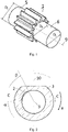
- bearing journal diameter D L which is approximately as large as a root diameter D F of the gearing. At least the bearing journal diameter D L is in the range of 90% to 100% of the root circle diameter D F . Of course, this also applies to the in 1 not shown bearing journal of the second gear.
- FIG. 2 shows a cross section through a plain bearing 3 according to the invention.
- the cut surface is placed transversely to the shaft axis 9 and centrally through a filling pocket 2 according to the invention, which is worked into the sliding surface of the plain bearing 3 according to the present invention.
- the interface is also in the still to be explained 3 drawn and labeled there with cut surface BB.
- the filling pocket 2 is spaced from a gear-side end face 7 of the plain bearing, so that a still to be explained web 11 with radial extension corresponding to the sliding surface of the plain bearing 3 is present.
- the position of the filling pocket 2 is defined below by angles about the shaft axis 9, ie the shaft axis 9 is in accordance with the section shown 2 defined as origin. Furthermore, angles are given in relation to an angular reference plane 10, which is spanned by the two shaft axes of the gear pump. In 2 , in which a section is shown transversely to the shaft axis 9, the reference plane 10 can be seen as a line running upwards, the reference direction for angle information (0° angle) is a ray which on the one hand emanates from the origin (shaft axis 9) and on the other hand perpendicularly through the second shaft axis (in 2 not shown) leads. Angles specified in the direction of rotation R of the shaft are positive and the angles opposite to the direction of rotation are therefore negative.
- the beginning of the filling pocket 2 can be specified with a start angle ⁇ and the end of the filling pocket 2 with an end angle ⁇ . It has been found that in a first embodiment the starting angle ⁇ is in a range from 225° to 315°, with a specific embodiment the starting angle ⁇ being equal to 270°. The end angle ⁇ is in a range from 315° to 360°, with the end angle ⁇ being equal to 330° in a specific embodiment variant.
- the filling pocket 2 has a small cross section at the beginning, ie in the area of the starting angle ⁇ , which becomes larger with increasing angle and which again decreases towards the end angle ⁇ . This is already from the in 2 shown section through the filling pocket 2 clearly visible.
- FIG 3 shows a section through the shaft axis 9 according to FIG 2 specified sectional plane CC through the inventive slide bearing 3.
- the filling pocket 2 and the lubricating groove communicating with it can be clearly seen 4, which in the embodiment variant shown is incorporated into the sliding surface of the plain bearing 3 at an angle ⁇ in relation to the shaft axis 9 of the plain bearing 3.
- the lubricating groove 4 has the task of supplying the plain bearing 3 with sufficient lubricant - ie the conveying medium - so that a lubricating film between the shaft and the plain bearing - in the so-called lubricating gap - does not tear off.
- the lubricating groove 4 is tapered, ie its cross section, which initially corresponds to the cross section of the filling pocket 2, decreases towards the sealing side. in the in 3
- a so-called dirt groove 13 is worked into the last third of the lubricating groove 4.
- the cross-section of the dirt groove is therefore dimensioned in such a way that the largest expected foreign particles in the pumped medium can be flushed out. Thus, clogging of the dirt groove and thus also of the lubricating groove 4 can be prevented.
- the filling pocket 2 is spaced far enough from the end face of the sliding bearing 3 that a web 11 with an axial extension corresponding to the surface of the slide bearing 3 remains. This ensures that foreign bodies that are larger than the sealing gap cannot get into the filling pocket 2 and thus also cannot get into the lubricating groove 4. Consequently, clogging of the lubricating groove 4 can be largely prevented, which leads to a significantly lower probability of failure of the gear pump.
- the gear pump according to the invention is therefore significantly more robust than known gear pumps.
- the gear pump according to the invention can therefore also be used to process conveying media such as polymer melts with a high proportion of solids or with solids above a critical size (foreign particles), which has not been the case up to now.
- the web 11 prevents too many or too large foreign particles from getting into the narrow lubricating gap between the shaft and the plain bearing 3 .
- the web 11 thus acts as a kind of filter which only allows foreign particles up to a certain size to pass through. If the lubricating groove 4 and the dirt groove that may be present are dimensioned according to the size of the foreign particles that can just pass through, an extremely robust gear pump is obtained because the lubricating groove 4 is prevented from becoming clogged and the lubricating film in the plain bearing 3 is thus prevented from breaking off.
- the geometry of the filling pocket 2 is designed in such a way that it initially becomes deeper in the direction of rotation of the shaft, ie the cross section increases in the direction of rotation of the shaft.
- the filling pocket 2 has a maximum width Br in the axial direction in relation to the shaft axis 9, which is 5% to 20%, preferably 10%, of the plain bearing length L.
- a distance d between the end face of the plain bearing 3 and the respective filling pocket 2 can be, for example, 5% to 10%, preferably 7% of the length L of the plain bearing.
- the distance d can be maintained, for example, over a significant part of the developed extent of the filler pocket 2, ie over more than 50%, in particular over more than 80% of the developed extent of the filler pocket 2.
- the distance d can include any radius in the case of a rounded transition from the end face to the plain bearing surface.
- the web 11 has a web width D in the axial direction at the level of the plain bearing surface, with the web width D being at least 1% to 10%, preferably 3%, of the plain bearing length L.
Landscapes
- Engineering & Computer Science (AREA)
- General Engineering & Computer Science (AREA)
- Mechanical Engineering (AREA)
- Rotary Pumps (AREA)
- Details And Applications Of Rotary Liquid Pumps (AREA)
- Extrusion Moulding Of Plastics Or The Like (AREA)
Abstract
Description
- Die vorliegende Erfindung betrifft eine Zahnradpumpe nach dem Oberbegriff von Anspruch 1 sowie eine Verwendung der Zahnradpumpe nach Anspruch 10.
- Zahnradpumpen bestehen im Wesentlichen aus einem Paar ineinandergreifender Zahnräder, die von einem Gehäuse umschlossen sind und von denen seitlich jeweils um die Längsachse angeordnete Lagerzapfen abstehen, die in Fördermedium-geschmierten Gleitlagern ihren Sitz haben.
- Da Zahnradpumpen eine fördersteife Kennlinie besitzen, eignen sie sich besonders gut für den Transport von Fördermedien von einer Saug- auf eine Druckseite. Zwischen beiden letzteren entsteht aufgrund des geförderten Volumenstromes in den Folgeaggregaten ein Druckgefälle, welches bei hochviskosen Medien besonders gross ist und zu einer Kraftübertragung auf jedes Zahnrad führt.
- Eine bekannte Zahnradpumpe ist beispielsweise in
EP-1 790 854 A1 beschrieben, wobei es sich hierbei um eine Zahnradpumpe handelt, bei der ein Lagerzapfendurchmesser nahezu oder gleich einem Fusskreisdurchmesser der Verzahnung entspricht. - Die bekannten Zahnradpumpen haben Gleitlager, die mit dem Fördermedium geschmiert werden. An den Gleitlagern liegt auf der einen Seite der Zahnradpumpen-austrittsseitige hohe Druck an, wogegen hinter dem Gleitlager annähernd saugseitiger Druck der Zahnradpumpe herrscht, der deutlich niedriger ist als der Druck auf der Seite des Pumpenaustritts. Durch diese Druckdifferenz strömt Fördermedium, das für den Schmierfilmaufbau im Gleitlager benötigt wird, vom Pumpenaustritt in das Gleitlager. Eine Druckschmiernut in der Stirnseite des Gleitlagers bildet hierbei eine direkte Verbindung in das Gleitlager, um Fördermedium in einer Schmiernut im Gleitlager möglichst ungestört in das Gleitlager zu leiten.
- Wird als Fördermedium eine Polymerschmelze verwendet, die zudem mit hohen Anteilen an Feststoffen oder mit Feststoffen oberhalb einer kritischen Grösse (Fremdpartikel) versetzt ist, stellt dies für eine ausreichende Schmierung im Gleitlager eine Schwierigkeit dar. Für eine gute Funktion der Gleitlager ist es wichtig, einen Schmierfilm aus Fördermedium aufzubauen. Gelangen zu viele oder zu grosse Fremdpartikel in den engen Schmierspalt zwischen Welle und Gleitlager, besteht die Gefahr eines Schadens am Gleitlager oder an der Welle, was zu einem Ausfall der Zahnradpumpe führt. Dies ist insbesondere bei einer Partikelgrösse der Fall, die grösser ist als die Höhe des Minimalschmierfilms, denn dies führt zu einer Unterbrechung des Schmiermittelflusses durch Verstopfung im Gleitlager und damit zu einem Ausfall der Zahnradpumpe. Ein erhöhter Durchfluss von Partikelbeladener Schmelze (Fördermedium) kann auch zu erhöhten abrasivem Verschleiss der Gleitlageroberflächen führen. Gelangt zu wenig Schmelze in das Gleitlager, besteht die Gefahr von Mangelschmierung.
- Ferner können bei einem Polymer als Fördermittel nicht geschmolzene Polymerpartikel (kleine Klumpen), die über die Schmiernut in das Gleitlager gelangen, den Schmierstrom blockieren und zu einem Ausfall der Zahnradpumpe führen.
- Es ist daher Aufgabe der vorliegenden Erfindung, eine Zahnradpumpe anzugeben, die mindestens einen der vorstehend genannten Nachteile nicht aufweist.
- Diese Aufgabe wird durch die im Kennzeichen von Anspruch 1 angegebenen Merkmalen gelöst. Weitere Ausführungsformen der vorliegenden Erfindung sowie eine Verwendung sind in weiteren abhängigen Ansprüchen definiert.
- Eine erfindungsgemässe Zahnradpumpe umfasst zunächst eine Zahnradpumpe mit ineinandergreifenden, von einem Gehäuse umschlossenen Zahnrädern mit auf Wellenachsen angeordneten, jeweils seitlich von den Zahnrädern abstehenden Lagerzapfen, die im Gehäuse mittels Gleitlager, aufweisend eine Gleitlagerlänge, gelagert sind, wobei die Gleitlager Fördermedium-geschmiert sind. Die vorliegende Erfindung zeichnet sich dadurch aus,
- dass in die Gleitlager jeweils eine Fülltasche mit radialer Ausdehnung im Bereich einer Pumpendruckseite eingearbeitet ist, wobei die Fülltasche von einer zahnradseitigen Stirnseite des jeweiligen Gleitlagers um einen Abstand beabstandet ist, so dass ein Steg mit einer Stegbreite mit axialer Ausdehnung entsprechend einer Gleitlageroberfläche bestehend ist, und
- dass in den Gleitlagern je eine Schmiernut mit, ausgehend von einem zahnradseitigen Ende hin zu einem Gleitlagerende, einem verjüngenden Querschnitt vorhanden ist, wobei die Schmiernut zahnradseitig bei der Fülltasche beginnt und mit dieser kommuniziert.
- Die erfindungsgemässe Zahnradpumpe ist damit im Vergleich zu bekannten Zahnradpumpen wesentlich robuster, denn es können bei einem Polymer als Fördermittel noch geschmolzene Polymerpartikel (kleine Klumpen) noch Fremdpartikel in die Schmiernut im Gleitlager gelangen. Der Schmierstrom wird daher weit weniger blockiert, wodurch die Ausfallwahrscheinlichkeit der erfindungsgemässen Zahnradpumpe deutlich geringer ist.
- Eine Ausführungsvariant der erfindungsgemässen Zahnradpumpe zeichnet sich dadurch aus, dass der Abstand zwischen der Stirnseite der Gleitlager und der jeweiligen Fülltasche 5% bis 10%, vorzugsweise 7%, der Gleitlagerlänge beträgt. Weitere Ausführungsvarianten der erfindungsgemässen Zahnradpumpe bestehen darin, dass die Stegbreite D 1% bis 10%, vorzugsweise 3%, der Gleitlagerlänge L beträgt.
- Weitere Ausführungsvarianten der erfindungsgemässen Zahnradpumpe bestehen darin, dass die Fülltasche in axialer Richtung in Bezug auf die Wellenachse eine maximale Breite aufweist, die 5% bis 20%, vorzugsweise 10%, der Gleitlagerlänge beträgt.
- Noch weitere Ausführungsvarianten der erfindungsgemässen Zahnradpumpe bestehen darin, dass die Fülltasche in Bezug auf eine durch die beiden Wellenachsen aufgespannte Ebene und in Drehrichtung der Zahnräder bei einem Winkel von 225° bis 315°, vorzugsweise bei 270°, beginnt.
- Weitere Ausführungsvarianten der erfindungsgemässen Zahnradpumpe bestehen darin, dass die Fülltasche in Bezug auf eine durch die beiden Wellenachsen aufgespannte Ebene und in Drehrichtung der Zahnräder bei einem Winkel von 315° bis 360°, vorzugsweise bei 330°, endet.
- Weitere Ausführungsvarianten der erfindungsgemässen Zahnradpumpe bestehen darin, dass ein Querschnitt im Übergangsbereich von der Fülltasche zur Schmiernut stetig ausgebildet ist.
- Weitere Ausführungsvarianten der erfindungsgemässen Zahnradpumpe bestehen darin, dass die Schmiernut in einem spitzen Winkel in Bezug auf die Wellenachse in Richtung Gleitlagerende verläuft.
- Weitere Ausführungsvarianten der erfindungsgemässen Zahnradpumpe bestehen darin, dass die Schmiernut bis ans Gleitlagerende verläuft.
- Weitere Ausführungsvarianten der erfindungsgemässen Zahnradpumpe bestehen darin, dass mindestens einer der Lagerzapfen zumindest über einen Teil seiner axialen Erstreckung einen Lagerzapfendurchmesser aufweist, der im Bereich von 90% bis 100% eines Fusskreisdurchmessers der Verzahnung des zugehörenden Zahnrades liegt.
- Schliesslich umfasst die vorliegende Erfindung eine Verwendung der Zahnradpumpe nach einer oder mehrerer der vorstehend genannten Ausführungsvarianten zur Förderung von hochviskosen Fördermedium, wie Polymer, mit einem Massenprozentanteil von Füllstoffen (z.B. Titandioxid TiO2, Calciumcarbonat, Holzmehl, Stein, Kreide, Talg, Talkum, Silicate, Kohlenstoffe, insbesondere in Form von Russ) von über 60% an der Gesamtmasse Fördermedium.
- Die erwähnten Ausführungsvarianten der vorliegenden Erfindung lassen sich in beliebiger Reihenfolge kombinieren. Lediglich diejenigen Kombinationen von Ausführungsvarianten sind ausgeschlossen, die durch die Kombination zu einem Widerspruch führen würden.
- Ausführungsbeispiele der vorliegenden Erfindung werden nachstehend anhand von Figuren noch näher erläutert. Diese dienen lediglich zur Erläuterung und sind nicht einschränkend auszulegen. Es zeigen:
- Fig. 1
- ein bekanntes Zahnrad mit Lagerzapfen für eine erfindungsgemässe Zahnradpumpe in perspektivischer Darstellung,
- Fig. 2
- einen Schnitt quer zur Wellenachse gemäss Schnittlinie B-B in
Fig. 3 durch ein erfindungsgemässes Gleitlager, - Fig. 3
- einen Schnitt durch die Wellenachse gemäss Schnittlinie C-C in
Fig. 2 durch das erfindungsgemässe Gleitlager gemässFig. 2 und - Fig. 4
- eine Draufsicht auf eine in das erfindungsgemässe Gleitlager eingearbeitete Fülltasche mit anschliessender Schmiernut.
-
Fig. 1 zeigt eine perspektivische Darstellung eines an sich bekannten Zahnrades 1 mit Lagerzapfen 5 und 6 für eine erfindungsgemässe Zahnradpumpe. Die Lagerzapfen 5 und 6 weisen über einen Teil ihrer axialen Erstreckung einen Lagerzapfendurchmesser DL auf, der annähernd so gross ist wie ein Fusskreisdurchmesser DF der Verzahnung. Zumindest liegt der Lagerzapfendurchmesser DL im Bereich von 90% bis 100% des Fusskreisdurchmessers DF. Selbstverständlich gilt dies auch für die inFig. 1 nicht dargestellten Lagerzapfen des zweiten Zahnrades. -
Fig. 2 zeigt einen Querschnitt durch ein erfindungsgemässes Gleitlager 3. Die Schnittfläche ist quer zur Wellenachse 9 und mittig durch eine erfindungsgemässe Fülltasche 2 gelegt, die in die Gleitfläche des Gleitlagers 3 gemäss der vorliegenden Erfindung eingearbeitet ist. Die Schnittfläche ist auch in der noch zu erläuterndenFig. 3 eingezeichnet und dort mit Schnittfläche B-B bezeichnet. - Wie bereits aus
Fig. 2 erkennbar ist, ist die Fülltasche 2 von einer Zahnrad-seitigen Stirnfläche 7 des Gleitlagers beabstandet, so dass ein noch zu erläuternder Steg 11 mit radialer Ausdehnung entsprechend der Gleitfläche des Gleitlagers 3 vorhanden ist. - Die Position der Fülltasche 2 wird im Folgenden durch Winkelangaben um die Wellenachse 9 definiert, d.h. die Wellenachse 9 ist im dargestellten Schnitt gemäss
Fig. 2 als Ursprung definiert. Ferner sind Winkel in Bezug auf eine Winkelbezugsebene 10 angegeben, die durch die beiden Wellenachsen der Zahnradpumpe aufgespannt wird. InFig. 2 , in der ein Schnitt quer zur Wellenachse 9 dargestellt ist, ist die Bezugsebene 10 als eine nach oben verlaufende Linie ersichtlich, wobei die Bezugsrichtung für Winkelangaben (0°-Winkel) ein Strahl ist, der einerseits vom Ursprung (Wellenachse 9) ausgeht und der andererseits senkrecht durch die zweite Wellenachse (inFig. 2 nicht dargestellt) führt. In Rotationsrichtung R der Welle angegebene Winkel sind dabei positiv und entgegen der Rotationsrichtung sind die Winkel somit negativ. - Ausgehend von diesen Definitionen kann ein Beginn der Fülltasche 2 mit einem Startwinkel α und das Ende der Fülltasche 2 mit einem Endwinkel β angegeben werden. Es hat sich erwiesen, dass bei einer ersten Ausführungsvariante der Startwinkel α in einem Bereich von 225° bis 315° liegt, wobei bei einer spezifischen Ausführungsvariante der Startwinkel α gleich 270° ist. Der Endwinkel β liegt in einem Bereich von 315° bis 360°, wobei bei einer spezifischen Ausführungsvariante der Endwinkel β gleich 330° ist.
- Die Fülltasche 2 weist bei einer Ausführungsvariante der vorliegenden Erfindung zu Beginn, d.h. im Bereich des Startwinkels α, einen kleinen Querschnitt auf, der mit zunehmendem Winkel grösser wird und der hin zum Endwinkel β wiederum abnimmt. Dies ist bereits aus dem in
Fig. 2 dargestellten Schnitt durch die Fülltasche 2 deutlich erkennbar. -
Fig. 3 zeigt einen Schnitt durch die Wellenachse 9 gemäss der inFig. 2 angegebenen Schnittebene C-C durch das erfindungsgemässe Gleitlager 3. Deutlich erkennbar ist die Fülltasche 2 und die mit dieser kommunizierenden Schmiernut 4, welche bei der gezeigten Ausführungsvariante in einem Winkel γ in Bezug zur Wellenachse 9 des Gleitlagers 3 in die Gleitfläche des Gleitlagers 3 eingearbeitet ist. Die Schmiernut 4 hat die Aufgabe, das Gleitlager 3 ausreichend mit Schmiermittel - d.h. Fördermedium - zu versorgen, damit ein Schmierfilm zwischen Welle und Gleitlager - im so genannten Schmierspalt - nicht abreisst. Hierzu ist die Schmiernut 4 verjüngend ausgestaltet, d.h. ihr Querschnitt, der zu Beginn mit dem Querschnitt der Fülltasche 2 übereinstimmt, nimmt hin zur Dichtseite ab. In der inFig. 3 dargestellten Ausführungsvariante der Erfindung ist im letzten Drittel der Schmiernut 4 eine so genannten Schmutznut 13 eingearbeitet, die im Wesentlichen einen konstanten Querschnitt aufweist und nach «hinten hin» offen ist, und dafür sorgt, dass Fremdpartikel aus dem Gleitlager 3 ausgeschwemmt werden. Der Querschnitt der Schmutznut wird daher derart bemessen, dass die grössten zu erwarteten Fremdpartikel im Fördermedium ausgeschwemmt werden können. Somit kann ein Verstopfen der Schmutznut und damit auch der Schmiernut 4 verhindert werden. - In
Fig. 4 ist eine Draufsicht auf die in das erfindungsgemässe Gleitlager 3 eingearbeitete Fülltasche 2 dargestellt. Ein Teil der mit der Fülltasche 2 verbundenen Schmiernut 4 ist ebenfalls ersichtlich. - Von entscheidender Bedeutung für die vorliegende Erfindung ist der Umstand, dass die Fülltasche 2 von der Stirnseite des Gleitlagers 3 so weit beabstandet ist, dass ein Steg 11 mit einer axialen Ausdehnung entsprechend der Oberfläche des Gleitlagers 3 bestehen bleibt. Damit ist gewährleitet, dass Fremdkörper, die grösser sind als der Dichtspalt, nicht in die Fülltasche 2 und damit auch nicht in die Schmiernut 4 gelangen können. Mithin kann ein Verstopfen der Schmiernut 4 weitgehend verhindert werden, was zu einer wesentlich geringeren Ausfallwahrscheinlichkeit der Zahnradpumpe führt. Die erfindungsgemässe Zahnradpumpe ist damit wesentlich robuster als bekannte Zahnradpumpen.
- Mit der erfindungsgemässen Zahnradpumpe können daher auch Fördermedien, wie beispielsweise Polymerschmelzen mit einem hohen Anteil an Feststoffen oder mit Feststoffen oberhalb einer kritischen Grösse (Fremdpartikel) bestens verarbeitet werden, was bis heute nicht der Fall war. Mit dem Steg 11 wird verhindert, dass zu viele oder zu grosse Fremdpartikel in den engen Schmierspalt zwischen Welle und Gleitlager 3 gelangen können. Der Steg 11 wirkt somit als eine Art Filter, der lediglich Fremdpartikel bis zu einer gewissen Grösse passieren lässt. Wird die Schmiernut 4 und die allenfalls vorhandene Schmutznut entsprechend der Grösse der gerade noch durchgelassenen Fremdpartikel dimensioniert, so wird eine überaus robuste Zahnradpumpe erhalten, denn ein Verstopfen der Schmiernut 4 und damit ein Abbrechen des Schmierfilmes im Gleitlager 3 werden verhindert.
- Die Geometrie der Fülltasche 2 ist so gestaltet, dass sie in Rotationsrichtung der Welle zunächst tiefer wird, d.h. der Querschnitt nimmt in Rotationsrichtung der Welle zu.
- Bei weiteren Ausführungsvarianten der vorliegenden Erfindung weist die Fülltasche 2 in axialer Richtung in Bezug auf die Wellenachse 9 eine maximale Breite Br auf, die 5% bis 20%, vorzugsweise 10%, der Gleitlagerlänge L beträgt. Hierbei kann ein Abstand d zwischen der Stirnseite der Gleitlager 3 und der jeweiligen Fülltasche 2 beispielsweise 5% bis 10%, vorzugsweise 7% der Gleitlagerlänge L betragen. Der Abstand d kann beispielsweise über einen wesentlichen Teil der abgewickelten Ausdehnung der Fülltasche 2, d.h. über mehr als 50%, insbesondere über mehr als 80% der abgewickelten Ausdehnung der Fülltasche 2 eingehalten werden. Ferner kann der Abstand d einen allfälligen Radius bei einem abgerundeten Übergang von der Stirnseite zur Gleitlageroberfläche umfassen. Wichtig ist bei einem Vorhandensein eines abgerundeten Überganges von der Stirnseite zur Gleitlageroberfläche, dass der Steg 11 eine Stegbreite D in axialer Richtung auf Niveau Gleitlageroberfläche aufweist, wobei die Stegbreite D, wobei die Stegbreite D mindestens 1% bis 10%, vorzugsweise 3%, der Gleitlagerlänge L beträgt.
-
- 1
- Zahnrad
- 2
- Fülltasche
- 3
- Gleitlager
- 4
- Schmiernut
- 5,6
- Lagerzapfen
- 7
- Zahnrad-seitige Stirnfläche
- R
- Rotationsrichtung der Welle
- 9
- Wellenachse
- 10
- Winkelbezugsebene
- 11
- Steg
- 12
- Übergangsbereich
- 13
- Schmutznut
- α
- Startwinkel
- β
- Endwinkel
- γ
- Neigewinkel
- DL
- Lagerzapfendurchmesser
- DF
- Fusskreisdurchmesser
- L
- Gleitlagerlänge
- Br
- Breite
- d
- Abstand der Fülltasche von der Stirnseite des Gleitlagers
- D
- Stegbreite
Claims (11)
- Zahnradpumpe mit ineinandergreifenden, von einem Gehäuse umschlossenen Zahnrädern (1) mit auf Wellenachsen (9) angeordneten, jeweils seitlich von den Zahnrädern (1) abstehenden Lagerzapfen (5, 6), die im Gehäuse mittels Gleitlager (3), aufweisend eine Gleitlagerlänge (L), gelagert sind, wobei die Gleitlager (3) Fördermedium-geschmiert sind, dadurch gekennzeichnet,- dass in die Gleitlager (3) jeweils eine Fülltasche (2) mit radialer Ausdehnung im Bereich einer Pumpendruckseite eingearbeitet ist, wobei die Fülltasche (2) von einer zahnradseitigen Stirnseite (7) des jeweiligen Gleitlagers (3) um einen Abstand (d) beabstandet ist, so dass ein Steg (11) mit einer Stegbreite (D) mit axialer Ausdehnung entsprechend einer Gleitlageroberfläche bestehend ist, und- dass in den Gleitlagern (3) je eine Schmiernut (4) mit, ausgehend von einem zahnradseitigen Ende hin zu einem Gleitlagerende, einem verjüngenden Querschnitt vorhanden ist, wobei die Schmiernut (4) zahnradseitig bei der Fülltasche (2) beginnt und mit dieser kommuniziert.
- Zahnradpumpe nach Anspruch 1, dadurch gekennzeichnet, dass der Abstand (d) zwischen der Stirnseite (7) der Gleitlager (3) und der jeweiligen Fülltasche (2) 5% bis 10%, vorzugsweise 7%, der Gleitlagerlänge (L) beträgt.
- Zahnradpumpe nach Anspruch 1 oder 2, dadurch gekennzeichnet, dass die Stegbreite (D) mindestens 1% bis 10%, vorzugsweise 3%, der Gleitlagerlänge (L) beträgt.
- Zahnradpumpe nach einem der vorangehenden Ansprüche, dadurch gekennzeichnet, dass die Fülltasche (2) in axialer Richtung in Bezug auf die Wellenachse (9) eine maximale Breite (Br) aufweist, die 5% bis 20%, vorzugsweise 10%, der Gleitlagerlänge (L) beträgt.
- Zahnradpumpe nach einem der vorangehenden Ansprüche, dadurch gekennzeichnet, dass die Fülltasche (2) in Bezug auf eine durch die beiden Wellenachsen (9) aufgespannte Ebene und in Drehrichtung der Zahnräder bei einem Winkel von 225° bis 315°, vorzugsweise bei 270°, beginnt.
- Zahnradpumpe nach einem der vorangehenden Ansprüche, dadurch gekennzeichnet, dass die Fülltasche (2) in Bezug auf eine durch die beiden Wellenachsen (9) aufgespannte Ebene und in Drehrichtung der Zahnräder (1) bei einem Winkel von 315° bis 360°, vorzugsweise bei 330°, endet.
- Zahnradpumpe nach einem der vorangehenden Ansprüche, dadurch gekennzeichnet, dass ein Querschnitt im Übergangsbereich (12) von der Fülltasche (2) zur Schmiernut (4) stetig ausgebildet ist.
- Zahnradpumpe nach einem der vorangehenden Ansprüche, dadurch gekennzeichnet, dass die Schmiernut (4) in einem spitzen Winkel (γ) in Bezug auf die Wellenachse (9) in Richtung Gleitlagerende verläuft.
- Zahnradpumpe nach einem der vorangehenden Ansprüche, dadurch gekennzeichnet, dass die Schmiernut (4) bis ans Gleitlagerende verläuft.
- Zahnradpumpe nach einem der vorangehenden Ansprüche, dadurch gekennzeichnet, dass mindestens einer der Lagerzapfen (5, 6) zumindest über einen Teil seiner axialen Erstreckung einen Lagerzapfendurchmesser (DL) aufweist, der im Bereich von 90% bis 100% eines Fusskreisdurchmessers (DF) der Verzahnung des zugehörenden Zahnrades (1) liegt.
- Verwendung der Zahnradpumpe nach einem der vorangehenden Ansprüche zur Förderung von hochviskosen Fördermedium, wie Polymer, mit einem Massenprozentanteil von anorganischen Füllstoffen an Gesamtmasse Fördermedium von über 60%.
Priority Applications (5)
| Application Number | Priority Date | Filing Date | Title |
|---|---|---|---|
| EP21171421.7A EP4083428B1 (de) | 2021-04-30 | 2021-04-30 | Zahnradpumpe und deren verwendung |
| PCT/EP2022/055752 WO2022228761A1 (de) | 2021-04-30 | 2022-03-07 | Zahnradpumpe und deren verwendung |
| JP2023567082A JP7890321B2 (ja) | 2021-04-30 | 2022-03-07 | ギアポンプ及びその使用方法 |
| CN202280031171.3A CN117203430A (zh) | 2021-04-30 | 2022-03-07 | 齿轮泵及其用途 |
| US18/287,999 US12180959B2 (en) | 2021-04-30 | 2022-03-07 | Gear pump with intermeshing gear wheels enclosed by housing with bearing journals arranged on shaft axes and use thereof |
Applications Claiming Priority (1)
| Application Number | Priority Date | Filing Date | Title |
|---|---|---|---|
| EP21171421.7A EP4083428B1 (de) | 2021-04-30 | 2021-04-30 | Zahnradpumpe und deren verwendung |
Publications (3)
| Publication Number | Publication Date |
|---|---|
| EP4083428A1 true EP4083428A1 (de) | 2022-11-02 |
| EP4083428B1 EP4083428B1 (de) | 2024-07-24 |
| EP4083428C0 EP4083428C0 (de) | 2024-07-24 |
Family
ID=75746386
Family Applications (1)
| Application Number | Title | Priority Date | Filing Date |
|---|---|---|---|
| EP21171421.7A Active EP4083428B1 (de) | 2021-04-30 | 2021-04-30 | Zahnradpumpe und deren verwendung |
Country Status (5)
| Country | Link |
|---|---|
| US (1) | US12180959B2 (de) |
| EP (1) | EP4083428B1 (de) |
| JP (1) | JP7890321B2 (de) |
| CN (1) | CN117203430A (de) |
| WO (1) | WO2022228761A1 (de) |
Cited By (2)
| Publication number | Priority date | Publication date | Assignee | Title |
|---|---|---|---|---|
| CN117052652A (zh) * | 2023-09-08 | 2023-11-14 | 中国神华煤制油化工有限公司 | 用于齿轮泵的轴瓦及包括其的齿轮泵、熔体输送装置 |
| EP4450756A1 (de) | 2023-04-20 | 2024-10-23 | Maag Pump Systems AG | Zahnradpumpe und deren verwendung |
Citations (5)
| Publication number | Priority date | Publication date | Assignee | Title |
|---|---|---|---|---|
| US2891483A (en) * | 1956-04-13 | 1959-06-23 | Thompson Ramo Wooldridge Inc | Movable bushing for pressure loaded gear pumps |
| DE2005740A1 (de) * | 1969-02-26 | 1970-09-10 | Hydroperfect International, Saint-Maur (Frankre i ch) | Gleitlager mit hydrodynamischer Schmierung |
| EP0833068A1 (de) * | 1996-09-30 | 1998-04-01 | Maag Pump Systems Textron AG | Gleitlager, insbesondere für eine Zahnradpumpe |
| DE10135709C1 (de) * | 2001-07-21 | 2003-02-13 | Hartmut Hasse | Universelle zwangsgeschmierte Gleitlagerung für eine Zahnradpumpe |
| EP1790854A1 (de) | 2005-11-28 | 2007-05-30 | Maag Pump Systems Textron AG | Zahnradpumpe |
Family Cites Families (10)
| Publication number | Priority date | Publication date | Assignee | Title |
|---|---|---|---|---|
| DE1528965A1 (de) * | 1965-08-10 | 1969-10-30 | Bosch Gmbh Robert | Verdraengungsmaschine |
| US5641281A (en) * | 1995-11-20 | 1997-06-24 | Lci Corporation | Lubricating means for a gear pump |
| US6338575B1 (en) * | 2000-05-02 | 2002-01-15 | Yen Sun Technic Industrial Corporation | Self-lubricating bearings and assemblies thereof |
| FR2882409B1 (fr) * | 2005-02-21 | 2008-09-05 | Ct Stephanois De Recherches | Organe de guidage autolubrifiant |
| CN101265902B (zh) * | 2008-04-16 | 2011-08-24 | 大连橡胶塑料机械股份有限公司 | 大型熔体齿轮泵中滑动轴承的强制性自润滑系统 |
| US8998496B2 (en) | 2012-03-30 | 2015-04-07 | Imo Industries, Inc. | Gear pump with asymmetrical dual bearing |
| US9140302B2 (en) * | 2013-06-13 | 2015-09-22 | The Boeing Company | Joint bearing lubricant system |
| MX386246B (es) * | 2014-07-22 | 2025-03-04 | Project Phoenix Llc | Bomba de engranajes externos integrada con dos motores de impulso accionados de forma independiente. |
| EP3091242A1 (de) * | 2015-05-08 | 2016-11-09 | Siemens Aktiengesellschaft | Gleitlager mit schmiernut |
| CN211598988U (zh) | 2019-12-13 | 2020-09-29 | 郑州机械研究所有限公司 | 熔体齿轮泵 |
-
2021
- 2021-04-30 EP EP21171421.7A patent/EP4083428B1/de active Active
-
2022
- 2022-03-07 WO PCT/EP2022/055752 patent/WO2022228761A1/de not_active Ceased
- 2022-03-07 CN CN202280031171.3A patent/CN117203430A/zh active Pending
- 2022-03-07 JP JP2023567082A patent/JP7890321B2/ja active Active
- 2022-03-07 US US18/287,999 patent/US12180959B2/en active Active
Patent Citations (5)
| Publication number | Priority date | Publication date | Assignee | Title |
|---|---|---|---|---|
| US2891483A (en) * | 1956-04-13 | 1959-06-23 | Thompson Ramo Wooldridge Inc | Movable bushing for pressure loaded gear pumps |
| DE2005740A1 (de) * | 1969-02-26 | 1970-09-10 | Hydroperfect International, Saint-Maur (Frankre i ch) | Gleitlager mit hydrodynamischer Schmierung |
| EP0833068A1 (de) * | 1996-09-30 | 1998-04-01 | Maag Pump Systems Textron AG | Gleitlager, insbesondere für eine Zahnradpumpe |
| DE10135709C1 (de) * | 2001-07-21 | 2003-02-13 | Hartmut Hasse | Universelle zwangsgeschmierte Gleitlagerung für eine Zahnradpumpe |
| EP1790854A1 (de) | 2005-11-28 | 2007-05-30 | Maag Pump Systems Textron AG | Zahnradpumpe |
Cited By (3)
| Publication number | Priority date | Publication date | Assignee | Title |
|---|---|---|---|---|
| EP4450756A1 (de) | 2023-04-20 | 2024-10-23 | Maag Pump Systems AG | Zahnradpumpe und deren verwendung |
| US12385483B2 (en) | 2023-04-20 | 2025-08-12 | Maag Pump Systems Ag | Gear pump with intermeshing gearwheels enclosed by housing with bearing journals arranged on shaft axes |
| CN117052652A (zh) * | 2023-09-08 | 2023-11-14 | 中国神华煤制油化工有限公司 | 用于齿轮泵的轴瓦及包括其的齿轮泵、熔体输送装置 |
Also Published As
| Publication number | Publication date |
|---|---|
| JP7890321B2 (ja) | 2026-07-14 |
| US20240200557A1 (en) | 2024-06-20 |
| US12180959B2 (en) | 2024-12-31 |
| EP4083428B1 (de) | 2024-07-24 |
| WO2022228761A1 (de) | 2022-11-03 |
| JP2024517207A (ja) | 2024-04-19 |
| EP4083428C0 (de) | 2024-07-24 |
| CN117203430A (zh) | 2023-12-08 |
Similar Documents
| Publication | Publication Date | Title |
|---|---|---|
| EP2683955B1 (de) | Gleitlagerschale | |
| EP4083428B1 (de) | Zahnradpumpe und deren verwendung | |
| AT503578A4 (de) | Dichtanordnung | |
| EP2852474B1 (de) | Schlagvorrichtung | |
| EP3273136B1 (de) | Vorrichtung zum leiten von schmiermittel aus einem schmiermittelsammelbehälter | |
| EP3091242A1 (de) | Gleitlager mit schmiernut | |
| DE2100365B2 (de) | Gleitlager mit Schmiernutensystem | |
| DE102012202454B4 (de) | Getriebevorrichtung mit einer Schmierölfördereinrichtung | |
| EP1219841B1 (de) | Gleitlager, insbesondere für eine Zahnradpumpe | |
| DE69721583T2 (de) | Ein paar zusammenwirkende schraubenrotoren | |
| EP0064598B1 (de) | Lagersegment für ein hydrodynamisches Gleitlager | |
| EP1284378B1 (de) | Wellendichtring mit verbesserter Funktion und Haltbarkeit | |
| EP1073845A1 (de) | Verdrängermaschine | |
| DE3129403A1 (de) | Vorrichtung fuer die kuehlmittelzufuhr zu mit kuehlmittelkanaelen versehenen, rotierenden schneidwerkzeugen fuer die spanende metallverarbeitung, insbesondere bohrwerkzeugen. | |
| DE10258861A1 (de) | Käfig für ein Wälzlager | |
| EP4450756A1 (de) | Zahnradpumpe und deren verwendung | |
| DE29521034U1 (de) | Spiralrillen-Gleitlager | |
| DE102018128372A1 (de) | Wälzkörperkäfig für ein Kegelrollenlager | |
| DE3045192C2 (de) | Zahnradpumpe | |
| EP0674746B1 (de) | Taumelscheibenmaschine | |
| WO2007131994A1 (de) | Zahnradpumpe | |
| EP0677660B1 (de) | Zahnradpumpe und deren Verwendung | |
| DE112004001454B4 (de) | Kolbenbolzenlager | |
| EP0628725A2 (de) | Zahnradpumpe | |
| EP1855008B1 (de) | Zahnradpumpe |
Legal Events
| Date | Code | Title | Description |
|---|---|---|---|
| PUAI | Public reference made under article 153(3) epc to a published international application that has entered the european phase |
Free format text: ORIGINAL CODE: 0009012 |
|
| STAA | Information on the status of an ep patent application or granted ep patent |
Free format text: STATUS: THE APPLICATION HAS BEEN PUBLISHED |
|
| AK | Designated contracting states |
Kind code of ref document: A1 Designated state(s): AL AT BE BG CH CY CZ DE DK EE ES FI FR GB GR HR HU IE IS IT LI LT LU LV MC MK MT NL NO PL PT RO RS SE SI SK SM TR |
|
| STAA | Information on the status of an ep patent application or granted ep patent |
Free format text: STATUS: REQUEST FOR EXAMINATION WAS MADE |
|
| 17P | Request for examination filed |
Effective date: 20230324 |
|
| RBV | Designated contracting states (corrected) |
Designated state(s): AL AT BE BG CH CY CZ DE DK EE ES FI FR GB GR HR HU IE IS IT LI LT LU LV MC MK MT NL NO PL PT RO RS SE SI SK SM TR |
|
| GRAP | Despatch of communication of intention to grant a patent |
Free format text: ORIGINAL CODE: EPIDOSNIGR1 |
|
| STAA | Information on the status of an ep patent application or granted ep patent |
Free format text: STATUS: GRANT OF PATENT IS INTENDED |
|
| GRAS | Grant fee paid |
Free format text: ORIGINAL CODE: EPIDOSNIGR3 |
|
| GRAA | (expected) grant |
Free format text: ORIGINAL CODE: 0009210 |
|
| STAA | Information on the status of an ep patent application or granted ep patent |
Free format text: STATUS: THE PATENT HAS BEEN GRANTED |
|
| INTG | Intention to grant announced |
Effective date: 20240603 |
|
| AK | Designated contracting states |
Kind code of ref document: B1 Designated state(s): AL AT BE BG CH CY CZ DE DK EE ES FI FR GB GR HR HU IE IS IT LI LT LU LV MC MK MT NL NO PL PT RO RS SE SI SK SM TR |
|
| REG | Reference to a national code |
Ref country code: GB Ref legal event code: FG4D Free format text: NOT ENGLISH |
|
| REG | Reference to a national code |
Ref country code: CH Ref legal event code: EP |
|
| REG | Reference to a national code |
Ref country code: DE Ref legal event code: R096 Ref document number: 502021004461 Country of ref document: DE |
|
| REG | Reference to a national code |
Ref country code: IE Ref legal event code: FG4D Free format text: LANGUAGE OF EP DOCUMENT: GERMAN |
|
| U01 | Request for unitary effect filed |
Effective date: 20240726 |
|
| U07 | Unitary effect registered |
Designated state(s): AT BE BG DE DK EE FI FR IT LT LU LV MT NL PT SE SI Effective date: 20240812 |
|
| PG25 | Lapsed in a contracting state [announced via postgrant information from national office to epo] |
Ref country code: NO Free format text: LAPSE BECAUSE OF FAILURE TO SUBMIT A TRANSLATION OF THE DESCRIPTION OR TO PAY THE FEE WITHIN THE PRESCRIBED TIME-LIMIT Effective date: 20241024 |
|
| PG25 | Lapsed in a contracting state [announced via postgrant information from national office to epo] |
Ref country code: PL Free format text: LAPSE BECAUSE OF FAILURE TO SUBMIT A TRANSLATION OF THE DESCRIPTION OR TO PAY THE FEE WITHIN THE PRESCRIBED TIME-LIMIT Effective date: 20240724 Ref country code: GR Free format text: LAPSE BECAUSE OF FAILURE TO SUBMIT A TRANSLATION OF THE DESCRIPTION OR TO PAY THE FEE WITHIN THE PRESCRIBED TIME-LIMIT Effective date: 20241025 |
|
| PG25 | Lapsed in a contracting state [announced via postgrant information from national office to epo] |
Ref country code: IS Free format text: LAPSE BECAUSE OF FAILURE TO SUBMIT A TRANSLATION OF THE DESCRIPTION OR TO PAY THE FEE WITHIN THE PRESCRIBED TIME-LIMIT Effective date: 20241124 |
|
| PG25 | Lapsed in a contracting state [announced via postgrant information from national office to epo] |
Ref country code: HR Free format text: LAPSE BECAUSE OF FAILURE TO SUBMIT A TRANSLATION OF THE DESCRIPTION OR TO PAY THE FEE WITHIN THE PRESCRIBED TIME-LIMIT Effective date: 20240724 |
|
| PG25 | Lapsed in a contracting state [announced via postgrant information from national office to epo] |
Ref country code: RS Free format text: LAPSE BECAUSE OF FAILURE TO SUBMIT A TRANSLATION OF THE DESCRIPTION OR TO PAY THE FEE WITHIN THE PRESCRIBED TIME-LIMIT Effective date: 20241024 Ref country code: ES Free format text: LAPSE BECAUSE OF FAILURE TO SUBMIT A TRANSLATION OF THE DESCRIPTION OR TO PAY THE FEE WITHIN THE PRESCRIBED TIME-LIMIT Effective date: 20240724 |
|
| PG25 | Lapsed in a contracting state [announced via postgrant information from national office to epo] |
Ref country code: RS Free format text: LAPSE BECAUSE OF FAILURE TO SUBMIT A TRANSLATION OF THE DESCRIPTION OR TO PAY THE FEE WITHIN THE PRESCRIBED TIME-LIMIT Effective date: 20241024 Ref country code: PL Free format text: LAPSE BECAUSE OF FAILURE TO SUBMIT A TRANSLATION OF THE DESCRIPTION OR TO PAY THE FEE WITHIN THE PRESCRIBED TIME-LIMIT Effective date: 20240724 Ref country code: NO Free format text: LAPSE BECAUSE OF FAILURE TO SUBMIT A TRANSLATION OF THE DESCRIPTION OR TO PAY THE FEE WITHIN THE PRESCRIBED TIME-LIMIT Effective date: 20241024 Ref country code: IS Free format text: LAPSE BECAUSE OF FAILURE TO SUBMIT A TRANSLATION OF THE DESCRIPTION OR TO PAY THE FEE WITHIN THE PRESCRIBED TIME-LIMIT Effective date: 20241124 Ref country code: HR Free format text: LAPSE BECAUSE OF FAILURE TO SUBMIT A TRANSLATION OF THE DESCRIPTION OR TO PAY THE FEE WITHIN THE PRESCRIBED TIME-LIMIT Effective date: 20240724 Ref country code: GR Free format text: LAPSE BECAUSE OF FAILURE TO SUBMIT A TRANSLATION OF THE DESCRIPTION OR TO PAY THE FEE WITHIN THE PRESCRIBED TIME-LIMIT Effective date: 20241025 Ref country code: ES Free format text: LAPSE BECAUSE OF FAILURE TO SUBMIT A TRANSLATION OF THE DESCRIPTION OR TO PAY THE FEE WITHIN THE PRESCRIBED TIME-LIMIT Effective date: 20240724 |
|
| PG25 | Lapsed in a contracting state [announced via postgrant information from national office to epo] |
Ref country code: SM Free format text: LAPSE BECAUSE OF FAILURE TO SUBMIT A TRANSLATION OF THE DESCRIPTION OR TO PAY THE FEE WITHIN THE PRESCRIBED TIME-LIMIT Effective date: 20240724 Ref country code: RO Free format text: LAPSE BECAUSE OF FAILURE TO SUBMIT A TRANSLATION OF THE DESCRIPTION OR TO PAY THE FEE WITHIN THE PRESCRIBED TIME-LIMIT Effective date: 20240724 |
|
| PG25 | Lapsed in a contracting state [announced via postgrant information from national office to epo] |
Ref country code: CZ Free format text: LAPSE BECAUSE OF FAILURE TO SUBMIT A TRANSLATION OF THE DESCRIPTION OR TO PAY THE FEE WITHIN THE PRESCRIBED TIME-LIMIT Effective date: 20240724 |
|
| PG25 | Lapsed in a contracting state [announced via postgrant information from national office to epo] |
Ref country code: SK Free format text: LAPSE BECAUSE OF FAILURE TO SUBMIT A TRANSLATION OF THE DESCRIPTION OR TO PAY THE FEE WITHIN THE PRESCRIBED TIME-LIMIT Effective date: 20240724 |
|
| PLBE | No opposition filed within time limit |
Free format text: ORIGINAL CODE: 0009261 |
|
| STAA | Information on the status of an ep patent application or granted ep patent |
Free format text: STATUS: NO OPPOSITION FILED WITHIN TIME LIMIT |
|
| U20 | Renewal fee for the european patent with unitary effect paid |
Year of fee payment: 5 Effective date: 20250425 |
|
| 26N | No opposition filed |
Effective date: 20250425 |
|
| U1N | Appointed representative for the unitary patent procedure changed after the registration of the unitary effect |
Representative=s name: EICHENBERGER, PHILIP; CH |
|
| PG25 | Lapsed in a contracting state [announced via postgrant information from national office to epo] |
Ref country code: MC Free format text: LAPSE BECAUSE OF FAILURE TO SUBMIT A TRANSLATION OF THE DESCRIPTION OR TO PAY THE FEE WITHIN THE PRESCRIBED TIME-LIMIT Effective date: 20240724 |
|
| GBPC | Gb: european patent ceased through non-payment of renewal fee |
Effective date: 20250430 |
|
| PG25 | Lapsed in a contracting state [announced via postgrant information from national office to epo] |
Ref country code: GB Free format text: LAPSE BECAUSE OF NON-PAYMENT OF DUE FEES Effective date: 20250430 |
|
| PG25 | Lapsed in a contracting state [announced via postgrant information from national office to epo] |
Ref country code: IE Free format text: LAPSE BECAUSE OF NON-PAYMENT OF DUE FEES Effective date: 20250430 |
|
| REG | Reference to a national code |
Ref country code: CH Ref legal event code: U11 Free format text: ST27 STATUS EVENT CODE: U-0-0-U10-U11 (AS PROVIDED BY THE NATIONAL OFFICE) Effective date: 20260501 |
|
| U20 | Renewal fee for the european patent with unitary effect paid |
Year of fee payment: 6 Effective date: 20260428 |
|
| PG25 | Lapsed in a contracting state [announced via postgrant information from national office to epo] |
Ref country code: CY Free format text: LAPSE BECAUSE OF FAILURE TO SUBMIT A TRANSLATION OF THE DESCRIPTION OR TO PAY THE FEE WITHIN THE PRESCRIBED TIME-LIMIT Effective date: 20240724 |
|
| PGFP | Annual fee paid to national office [announced via postgrant information from national office to epo] |
Ref country code: CH Payment date: 20260501 Year of fee payment: 6 |
|
| PGFP | Annual fee paid to national office [announced via postgrant information from national office to epo] |
Ref country code: TR Payment date: 20260424 Year of fee payment: 6 |