EP4083390B1 - Doppelbürstendichtungsanordnung - Google Patents
Doppelbürstendichtungsanordnung Download PDFInfo
- Publication number
- EP4083390B1 EP4083390B1 EP22170346.5A EP22170346A EP4083390B1 EP 4083390 B1 EP4083390 B1 EP 4083390B1 EP 22170346 A EP22170346 A EP 22170346A EP 4083390 B1 EP4083390 B1 EP 4083390B1
- Authority
- EP
- European Patent Office
- Prior art keywords
- backing plate
- gas turbine
- turbine engine
- brush
- array
- Prior art date
- Legal status (The legal status is an assumption and is not a legal conclusion. Google has not performed a legal analysis and makes no representation as to the accuracy of the status listed.)
- Active
Links
Images


Classifications
-
- F—MECHANICAL ENGINEERING; LIGHTING; HEATING; WEAPONS; BLASTING
- F01—MACHINES OR ENGINES IN GENERAL; ENGINE PLANTS IN GENERAL; STEAM ENGINES
- F01D—NON-POSITIVE DISPLACEMENT MACHINES OR ENGINES, e.g. STEAM TURBINES
- F01D11/00—Preventing or minimising internal leakage of working-fluid, e.g. between stages
- F01D11/005—Sealing means between non relatively rotating elements
-
- F—MECHANICAL ENGINEERING; LIGHTING; HEATING; WEAPONS; BLASTING
- F01—MACHINES OR ENGINES IN GENERAL; ENGINE PLANTS IN GENERAL; STEAM ENGINES
- F01D—NON-POSITIVE DISPLACEMENT MACHINES OR ENGINES, e.g. STEAM TURBINES
- F01D11/00—Preventing or minimising internal leakage of working-fluid, e.g. between stages
- F01D11/08—Preventing or minimising internal leakage of working-fluid, e.g. between stages for sealing space between rotor blade tips and stator
-
- F—MECHANICAL ENGINEERING; LIGHTING; HEATING; WEAPONS; BLASTING
- F01—MACHINES OR ENGINES IN GENERAL; ENGINE PLANTS IN GENERAL; STEAM ENGINES
- F01D—NON-POSITIVE DISPLACEMENT MACHINES OR ENGINES, e.g. STEAM TURBINES
- F01D11/00—Preventing or minimising internal leakage of working-fluid, e.g. between stages
- F01D11/003—Preventing or minimising internal leakage of working-fluid, e.g. between stages by packing rings; Mechanical seals
-
- F—MECHANICAL ENGINEERING; LIGHTING; HEATING; WEAPONS; BLASTING
- F05—INDEXING SCHEMES RELATING TO ENGINES OR PUMPS IN VARIOUS SUBCLASSES OF CLASSES F01-F04
- F05D—INDEXING SCHEME FOR ASPECTS RELATING TO NON-POSITIVE-DISPLACEMENT MACHINES OR ENGINES, GAS-TURBINES OR JET-PROPULSION PLANTS
- F05D2220/00—Application
- F05D2220/30—Application in turbines
- F05D2220/32—Application in turbines in gas turbines
-
- F—MECHANICAL ENGINEERING; LIGHTING; HEATING; WEAPONS; BLASTING
- F05—INDEXING SCHEMES RELATING TO ENGINES OR PUMPS IN VARIOUS SUBCLASSES OF CLASSES F01-F04
- F05D—INDEXING SCHEME FOR ASPECTS RELATING TO NON-POSITIVE-DISPLACEMENT MACHINES OR ENGINES, GAS-TURBINES OR JET-PROPULSION PLANTS
- F05D2230/00—Manufacture
- F05D2230/20—Manufacture essentially without removing material
- F05D2230/23—Manufacture essentially without removing material by permanently joining parts together
- F05D2230/232—Manufacture essentially without removing material by permanently joining parts together by welding
-
- F—MECHANICAL ENGINEERING; LIGHTING; HEATING; WEAPONS; BLASTING
- F05—INDEXING SCHEMES RELATING TO ENGINES OR PUMPS IN VARIOUS SUBCLASSES OF CLASSES F01-F04
- F05D—INDEXING SCHEME FOR ASPECTS RELATING TO NON-POSITIVE-DISPLACEMENT MACHINES OR ENGINES, GAS-TURBINES OR JET-PROPULSION PLANTS
- F05D2230/00—Manufacture
- F05D2230/60—Assembly methods
-
- F—MECHANICAL ENGINEERING; LIGHTING; HEATING; WEAPONS; BLASTING
- F05—INDEXING SCHEMES RELATING TO ENGINES OR PUMPS IN VARIOUS SUBCLASSES OF CLASSES F01-F04
- F05D—INDEXING SCHEME FOR ASPECTS RELATING TO NON-POSITIVE-DISPLACEMENT MACHINES OR ENGINES, GAS-TURBINES OR JET-PROPULSION PLANTS
- F05D2240/00—Components
- F05D2240/10—Stators
- F05D2240/11—Shroud seal segments
-
- F—MECHANICAL ENGINEERING; LIGHTING; HEATING; WEAPONS; BLASTING
- F05—INDEXING SCHEMES RELATING TO ENGINES OR PUMPS IN VARIOUS SUBCLASSES OF CLASSES F01-F04
- F05D—INDEXING SCHEME FOR ASPECTS RELATING TO NON-POSITIVE-DISPLACEMENT MACHINES OR ENGINES, GAS-TURBINES OR JET-PROPULSION PLANTS
- F05D2240/00—Components
- F05D2240/55—Seals
- F05D2240/56—Brush seals
-
- Y—GENERAL TAGGING OF NEW TECHNOLOGICAL DEVELOPMENTS; GENERAL TAGGING OF CROSS-SECTIONAL TECHNOLOGIES SPANNING OVER SEVERAL SECTIONS OF THE IPC; TECHNICAL SUBJECTS COVERED BY FORMER USPC CROSS-REFERENCE ART COLLECTIONS [XRACs] AND DIGESTS
- Y02—TECHNOLOGIES OR APPLICATIONS FOR MITIGATION OR ADAPTATION AGAINST CLIMATE CHANGE
- Y02T—CLIMATE CHANGE MITIGATION TECHNOLOGIES RELATED TO TRANSPORTATION
- Y02T50/00—Aeronautics or air transport
- Y02T50/60—Efficient propulsion technologies, e.g. for aircraft
Definitions
- This disclosure relates to gas turbine engines, and more particularly to sealing arrangements incorporating brush seals.
- Gas turbine engines typically include a compressor section and a turbine section.
- the air is compressed in the compressor section. From the compressor section the air is introduced into a combustor section where it is mixed with fuel and ignited in a combustor. Products of this combustion pass downstream over a turbine section to extract energy for driving the compressor section.
- the components may be exposed to hot gases in the gas path.
- Various cooling schemes may be utilized to cool portions of the components.
- a seal may be utilized to limit flow of hot gases from the gas path and/or cooling flow into the gas path.
- US 2019/032786 A1 discloses a prior art gas turbine engine as set forth in the preamble of claim 1.
- US 2019/309642 A1 discloses a prior art multi-plane brush seal.
- the present disclosure may include any one or more of the individual features disclosed above and/or below alone or in any combination thereof.
- FIG. 1 schematically illustrates a gas turbine engine 20.
- the gas turbine engine 20 is disclosed herein as a two-spool turbofan that generally incorporates a fan section 22, a compressor section 24, a combustor section 26 and a turbine section 28.
- the fan section 22 drives air along a bypass flow path B in a bypass duct defined within a housing 15 such as a fan case or nacelle, and also drives air along a core flow path C for compression and communication into the combustor section 26 then expansion through the turbine section 28.
- the exemplary engine 20 generally includes a low speed spool 30 and a high speed spool 32 mounted for rotation about an engine central longitudinal axis A relative to an engine static structure 36 via several bearing systems 38. It should be understood that various bearing systems 38 at various locations may alternatively or additionally be provided, and the location of bearing systems 38 may be varied as appropriate to the application.
- the low speed spool 30 generally includes an inner shaft 40 that interconnects, a first (or low) pressure compressor 44 and a first (or low) pressure turbine 46.
- the inner shaft 40 is connected to the fan 42 through a speed change mechanism, which in exemplary gas turbine engine 20 is illustrated as a geared architecture 48 to drive a fan 42 at a lower speed than the low speed spool 30.
- the high speed spool 32 includes an outer shaft 50 that interconnects a second (or high) pressure compressor 52 and a second (or high) pressure turbine 54.
- a combustor 56 is arranged in the exemplary gas turbine 20 between the high pressure compressor 52 and the high pressure turbine 54.
- a mid-turbine frame 57 of the engine static structure 36 may be arranged generally between the high pressure turbine 54 and the low pressure turbine 46.
- the mid-turbine frame 57 further supports bearing systems 38 in the turbine section 28.
- the inner shaft 40 and the outer shaft 50 are concentric and rotate via bearing systems 38 about the engine central longitudinal axis A which is collinear with their longitudinal axes.
- the core airflow is compressed by the low pressure compressor 44 then the high pressure compressor 52, mixed and burned with fuel in the combustor 56, then expanded through the high pressure turbine 54 and low pressure turbine 46.
- the mid-turbine frame 57 includes airfoils 59 which are in the core airflow path C.
- the turbines 46, 54 rotationally drive the respective low speed spool 30 and high speed spool 32 in response to the expansion.
- gear system 48 may be located aft of the low pressure compressor, or aft of the combustor section 26 or even aft of turbine section 28, and fan 42 may be positioned forward or aft of the location of gear system 48.
- the engine 20 in one example is a high-bypass geared aircraft engine.
- the engine 20 bypass ratio is greater than about six (6), with an example embodiment being greater than about ten (10), and can be less than or equal to about 18.0, or more narrowly can be less than or equal to 16.0.
- the geared architecture 48 is an epicyclic gear train, such as a planetary gear system or other gear system, with a gear reduction ratio of greater than about 2.3.
- the gear reduction ratio may be less than or equal to 4.0.
- the low pressure turbine 46 has a pressure ratio that is greater than about five.
- the low pressure turbine pressure ratio can be less than or equal to 13.0, or more narrowly less than or equal to 12.0.
- the engine 20 bypass ratio is greater than about ten (10:1)
- the fan diameter is significantly larger than that of the low pressure compressor 44
- the low pressure turbine 46 has a pressure ratio that is greater than about five 5:1.
- Low pressure turbine 46 pressure ratio is pressure measured prior to an inlet of low pressure turbine 46 as related to the pressure at the outlet of the low pressure turbine 46 prior to an exhaust nozzle.
- the geared architecture 48 may be an epicycle gear train, such as a planetary gear system or other gear system, with a gear reduction ratio of greater than about 2.3:1 and less than about 5:1. It should be understood, however, that the above parameters are only exemplary of one embodiment of a geared architecture engine and that the present invention is applicable to other gas turbine engines including direct drive turbofans.
- the fan section 22 of the engine 20 is designed for a particular flight condition -- typically cruise at about 0.8 Mach and about 35,000 feet (10,668 meters).
- the flight condition of 0.8 Mach and 35,000 ft (10,668 meters), with the engine at its best fuel consumption - also known as "bucket cruise Thrust Specific Fuel Consumption ('TSFC')" - is the industry standard parameter of lbm of fuel being burned divided by lbf of thrust the engine produces at that minimum point.
- 'TSFC' Thrust Specific Fuel Consumption
- “Low fan pressure ratio” is the pressure ratio across the fan blade alone, without a Fan Exit Guide Vane (“FEGV”) system.
- the low fan pressure ratio as disclosed herein according to one non-limiting embodiment is less than about 1.45, or more narrowly greater than or equal to 1.25.
- the "Low corrected fan tip speed" as disclosed herein according to one non-limiting embodiment is less than about 1150.0 ft / second (350.5 meters/second), and can be greater than or equal to 1000.0 ft / second (304.8 meters/second).
- Figure 2 illustrates an exemplary section 60 for a gas turbine engine.
- the section 60 may be incorporated into the gas turbine engine 20 of Figure 1 , such as the compressor section 24 or the turbine section 28.
- the section 60 includes a rotor 61 carrying one or more blades or airfoils 62 that are rotatable about a longitudinal axis LA.
- the longitudinal axis LA may be collinear or otherwise parallel to the engine axis A of Figure 1 .
- Each airfoil 62 includes a platform 62P and an airfoil section 62A extending in a radial direction R from the platform 62P to a tip 62T.
- the airfoil section 62A generally extends in a chordwise or axial direction X between a leading edge 62LE and a trailing edge 62TE.
- a root section 62R of the airfoil 62 is mounted to, or integrally formed with, the rotor 61.
- a blade outer air seal (BOAS) 63 is spaced radially outward from the tip 62T of the adjacent airfoil 62.
- the BOAS 63 can include a plurality of seal arc segments that are circumferentially arranged in an annulus around the longitudinal axis LA.
- the tip 62T of the airfoil section 62A and adjacent BOAS 63 are arranged in close radial proximity to reduce the amount of gas flow that is redirected toward and over the rotating blade airfoil tip 62T through a corresponding clearance gap.
- the BOAS 63 can include one or more seal arc segments 63 S mounted or otherwise secured to one or more carriers 63C. Each carrier 63C can be secured to an engine static structure such as the engine case 37 or another portion of the engine static structure 36 of Figure 1 .
- a vane 64 can be positioned along the longitudinal axis LA and adjacent to the airfoil 62.
- the vane 64 includes an airfoil section 64A extending between an inner platform 64PI and an outer platform 64PO to define a portion of the gas path GP.
- the inner platform 64PI and outer platform 64PO are dimensioned to bound radially inner and outer portions of the gas path GP.
- Each vane 64 can include a spar member 65 secured to a fairing 66.
- the spar member 65 may include a portion 65P at least partially received in a cavity 66C of the fairing 66.
- the portion 65P may be a hollow strut or conduit that extends radially inwardly towards the longitudinal axis LA.
- the spar member 65 may be secured to the engine static structure.
- the spar member 65 may be a load bearing structure that is dimensioned to at least partially support a respective fairing 66.
- the spar member 65 may be coupled to a coolant source CS (shown in dashed lines for illustrative purposes).
- the coolant source CS can be configured to supply or convey pressurized cooling flow to cool portions of the section 60 including each vane 64.
- the coolant source CS can include bleed air from an upstream stage of the compressor section 24 ( Figure 1 ), bypass air, or a secondary cooling system aboard the aircraft, for example.
- Various materials may be utilized to form the spar member 65 and fairing 66.
- the spar member 65 may be formed of a metallic material, such as a high temperature metal or alloy.
- the fairing 66 can be a monolithic component formed of a ceramic material, such as a ceramic matrix composite (CMC) material that establishes the airfoil section 64A and/or platform sections 64PI, 64PO.
- CMC ceramic matrix composite
- the CMC materials disclosed herein may include continuous or discontinuous fibers in a matrix arranged in one or more layers to establish a CMC layup.
- the section 60 can include an array of airfoils 62, an array of vanes 64, and an array of BOAS 63 arranged circumferentially about the longitudinal axis LA.
- the array of the BOAS 63 can be distributed in a circumferential or thickness direction T about an array of the airfoils 62 to bound a gas path GP, such as the core flow path C of Figure 1 .
- the section 60 can include one or more seal assemblies 70.
- Each seal assembly 70 can be arranged to establish sealing relationships with one or more adjacent gas turbine engine components of the section 60, such as a first gas turbine engine component 68 and second gas turbine engine component 69 adjacent the gas path GP.
- the first component 68 can be an adjacent vane(s) 64
- the second component 69 can be an adjacent BOAS 63 as illustrated in Figure 2 , or vice versa.
- the section 60 can include two or more seal assemblies 70 distributed along the longitudinal axis LA to establish sealing relationships that limit flow to and/or from the gas path GP.
- Figures 3-4 illustrate an exemplary seal assembly 170 for a section 160 of a gas turbine engine.
- the section 160 and seal assembly 170 may be incorporated into a section of the gas turbine engine 20 of Figures 1 and/or 2, such as the turbine section 28.
- Other portions of the gas turbine engine 20 and other systems may benefit from the teachings disclosed herein, including gas turbine engines lacking a fan for propulsion.
- like reference numerals designate like elements where appropriate and reference numerals with the addition of one-hundred or multiples thereof designate modified elements that are understood to incorporate the same features and benefits of the corresponding original elements.
- the seal assembly 170 can be arranged to establish sealing relationships with non-rotating or static components and/or rotating components such as shafts and bearing arrangements (e.g., inner shaft 40 or outer shaft 50 of Figure 1 ).
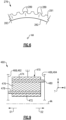
- the seal assembly 170 can include a first side plate 172, second side plate 174, backing plate 176, first brush seal 178 and second brush seal 180.
- the first side plate 172, second side plate 174, backing plate 176 and brush seals 178, 180 can be dimensioned to extend circumferentially about an assembly axis AA, as illustrated in Figure 3 .
- the assembly axis AA may be colinear with or otherwise parallel to a longitudinal axis LA of the section 160.
- the seal assembly 170 can be dimensioned to extend along an array of vanes 164 and/or array of BOAS 163 in the circumferential direction T as illustrated in Figure 3 and/or span between the array of vanes 164 and array of BOAS 163 in the axial direction X as illustrated by Figure 4 .
- Each of the first side plate 172, second side plate 174, backing plate 176 and/or brush seals 178, 180 can be a full hoop or can include one or more arc segments dimensioned to extend at least partially or completely about the assembly axis AA.
- the first and second brush seals 178, 180 may cooperate to establish a double brush seal arrangement.
- the first brush seal 178 can include a first bristle pack 179.
- the second brush seal 180 can include a second bristle pack 181.
- Each bristle pack 179, 181 can include a set of bristles that are joined together as a unit.
- the bristles may be formed of non-metallic materials or metallic materials such as high temperature metal or nickel-based alloy.
- the seal assembly 170 can have a unitary construction.
- the bristle packs 179, 181 may be arranged in a compressed state between the side plates 172, 174 and backing plate 176.
- the first bristle pack 179 can be welded or otherwise mechanically attached to the first side plate 172 and backing plate 176 and the second bristle pack 181 can be welded or otherwise mechanically attached to the second side plate 174 and backing plate 176 to establish the unitary construction.
- the first brush seal 178 and second brush seal 180 can be arranged in various configurations.
- the first and second brush seals 178, 180 can be positioned on opposite sides of the backing plate 176.
- the first brush seal 178 can be sandwiched or otherwise situated between the first side plate 172 and backing plate 176.
- the second brush seal 180 can be sandwiched or otherwise situated between the second side plate 174 and backing plate 176.
- the first and/or second side plates 172, 174 are omitted.
- the first and second brush seals 178, 180 can be arranged at various positions and/or orientations relative to each other and one or more gas turbine engine components to establish respective sealing relationships.
- the brush seals 178, 180 can be dimensioned to extend radially inward and/or radially outward in the same or different directions relative to the assembly axis AA, or can be dimensioned to extend axially in the same or different directions relative to the assembly axis AA.
- the first brush seal 178 can be dimensioned to establish a first sealing relationship with a first gas turbine engine component 168.
- the second brush seal 180 can be dimensioned to establish a second seal relationship with a second gas turbine engine component 169.
- the gas turbine engine components 168, 169 can include any of the components disclosed herein.
- the components 168, 169 can be different portions of the same gas turbine engine component or can be separate and distinct components.
- the first component 168 can be a turbine vane or associated mounting structure, such as the vane 164
- the second component 169 can be a BOAS or associated mounting structure, such as the BOAS 163 or the carrier 63C ( Figure 2 ).
- the first brush seal 178 is dimensioned to establish a first sealing relationship with the array of vanes 164
- the second brush seal 180 is dimensioned to establish the second sealing relationship with the array of blade outer air seals 163.
- first and second components 168, 169 may be utilized to form the first and second components 168, 169, including any of the materials disclosed herein.
- portions of the first and/or second components 168, 169 that establish the respective first and/or second sealing relationships may comprise a ceramic material such as a monolithic ceramic or CMC material.
- Monolithic ceramics may be, but are not limited to, silicon carbide (SiC) or silicon nitride (Si 3 N 4 ).
- the array of vanes 164 and array of BOAS 163 can establish an axial gap G relative to the longitudinal axis LA, as illustrated in Figure 4 .
- the axial gap G extends outwardly from a gas path GP such as the core flow path C of Figure 1 .
- the seal assembly 170 can be dimensioned to span the axial gap G between adjacent vanes 164 and BOAS 163.
- Each of the vanes 164 can include a fairing 166 that establishes a platform section 164P of the vane 164.
- the platform section 164P can be one of the platform sections 64PI, 64PO of the vane 64 of Figure 2 , such as the outer platform section 64PO.
- the platform section 164P can be arranged to establish the first and/or sealing relationships with the respective brush seal 178, 180, such as the first brush seal 178 as illustrated in Figures 3-4 , and can comprise any of the materials disclosed herein.
- the first and second brush seals 178, 180 are dimensioned to extend radially inward in the radial direction R from an inner periphery 182 of the backing plate 176 relative to the assembly axis AA to establish the first and second sealing relationships.
- the first and second brush seals 178, 180 can be dimensioned such that the first and second sealing relationships are established at the same radial position or at different radial positions relative to the longitudinal axis LA as illustrated in Figure 4 .
- the seal assembly 170 may be dimensioned to be trapped between one or more (or each) of the spar members 165 and one or more (or each) of the BOAS 163 opposing the spar members 165 in an installed position, as illustrated in Figures 3-4 . In the installed position, the spar members 165 and BOAS 163 cooperate to limit axial movement of the seal assembly 170 relative to the longitudinal axis LA.
- the second side plate 174 can include a plate body 184 and an annular flange 186 extending outwardly from the plate body 184.
- the annular flange 186 can be dimensioned to extend circumferentially in the circumferential direction T about the assembly axis AA.
- the annular flange 186 can be dimensioned to engage an outer periphery of the second component 169 (or first component 168), such as an outer periphery 163PO of two or more BOAS 163 as illustrated in Figure 3 to secure the seal assembly 170 to an engine static structure, such as the engine static structure 36 of Figure 1 .
- Engagement between the annular flange 186 and second component 169 can limit radial movement of the seal assembly 170 in the radial direction R relative to the longitudinal axis LA.
- the brush seals 178, 180 can be arranged at various orientations relative to each other to establish the respective sealing relationships.
- the backing plate 176 can have a generally quadrilateral or trapezoidal cross sectional geometry.
- the backing plate 176 can include a main body 183 extending radially between the inner periphery 182 and an outer periphery 191 and circumferentially between first and second sidewalls 185, 187 on opposite sides of the main body 183.
- the inner and outer peripheries 182, 191 can be substantially parallel to each other or can be transverse as illustrated in Figure 4 .
- the sidewalls 185, 187 can be substantially parallel to each other or can be transverse as illustrated in Figure 4 .
- the sidewalls 185, 187 can be dimensioned such that the brush seals 178, 180 slope outwardly from the outer periphery 191 of the backing plate 176 towards the inner periphery 182 of the backing plate 176.
- the first sidewall 185 can be dimensioned such that the first brush seal 178 slopes outwardly from the outer periphery 191 in a first direction D1 relative to the assembly axis AA.
- the second sidewall 187 can be dimensioned such that the second brush seal 180 slopes outwardly from the outer periphery 191 in a second direction D2 relative to the assembly axis AA, as illustrated in Figure 4 .
- the second direction D2 can be opposed to the first direction D1.
- the sidewalls 185, 187 can be dimensioned to have a major component in the radial direction R and a minor a component in the axial direction X to establish the sloping arrangement.
- the first and/or second brush seals 178, 180 can be angled approximately 5 degrees to approximately 45 degrees relative to a radial axis RA extending in the radial direction R (RA shown in dashed lines in Figure 4 for illustrative purposes).
- RA shown in dashed lines in Figure 4 for illustrative purposes.
- the backing plate 176 can include various weight reduction features.
- backing plate 276 includes one or more scallops 289 formed in a main body 283 of the backing plate 276.
- the backing plate 276 can include a plurality of scallops 289 circumferentially distributed about a periphery of the backing plate 276, such as an outer periphery 291.
- the scallops 289 can be formed in the backing plate 276 to reduce an overall weight of the seal assembly.
- Figures 7-8 illustrate a section 360 including a seal assembly 370 according to another example.
- the seal assembly 370 can include one or more anti-rotation features that clock the seal assembly 370 and limit relative movement between the seal assembly 370 and adjacent components 368, 369.
- the anti-rotation features can include one or more protrusions or keys 393 that may mate or interfit with respective recesses or keyways 395 associated with the components 368, 369 to limit relative rotation.
- the keys 393 may extend outwardly from one of the side plates 372, 374, such as the first side plate 372.
- the keyways 395 may be established in the one of the gas turbine engine components 368, 369 or associated support structure, such as one or more of the spars 365 (shown in dashed lines in Figure 7 for illustrative purposes). Each keyway 395 is dimensioned to interfit with a respective one of the keys 393 to limit circumferential movement in the circumferential direction T between the seal assembly 370 and adjacent components 368, 369.
- the section 360 can include an array of the keys 393 and keyways 395 distributed about the longitudinal axis LA.
- the anti-rotation features are incorporated in the second side plate 374 and the second component 369 or associated structure.
- Figure 9 illustrates a seal assembly 470 according to another example which does not fall under the scope of the appended claims.
- the seal assembly 470 can be secured to an engine static structure, including any of the static structures disclosed herein.
- the seal assembly 470 includes a first brush seal 478 and a second brush seal 480.
- the first brush seal 478 is dimensioned to establish a first sealing relationship with a first gas turbine engine component 468.
- the second brush seal 480 is dimensioned to establish a second sealing relationship with a second gas turbine engine component 469.
- the first brush seal 478 can be dimensioned to extend in a first axial direction D1 from a backing plate 476 relative to an assembly axis AA such that the first sealing relationships established along an axial face 492 of the first component 468.
- the axial face 492 may be established by one or more of the spar members 165 of Figures 3-4 , for example.
- the second brush seal 480 can be dimensioned to extend in a second axial direction D2 from the backing plate 476 relative to the assembly axis AA such that a second sealing relationship is established along an axial face 494 of the second component 469.
- the second axial direction D2 can be opposed to the first axial direction D1.
- the axial face 494 may be established by one or more BOAS 163 of Figures 3-4 or one or more carriers 63C associated with the BOAS 63 of Figure 2 , for example.
- the brush seals 478, 480 extend generally in the same direction.
- Figure 10 illustrates an exemplary method of assembly for a gas turbine engine in a flowchart 596. The method may be utilized to assemble any of the sections and seal assemblies disclosed herein. Reference is made to the seal assembly 170 of Figures 3-4 for illustrative purposes.
- Step 596A the first brush seal 178 and second brush seal 180 are positioned relative the backing plate 176.
- Step 596A can include positioning the first brush seal 178 and second brush seal 180 on opposite sides of the backing plate 176.
- Step 596B the first brush seal 178 and second brush seal 180 are positioned relative to the first side plate 172 and second side plate 174.
- Step 596B can include positioning the first and second brush seals 178, 180 between the side plates 172, 174 such that the first brush seal 178 is sandwiched between the first side plate 172 and backing plate 176 and such that the second brush seal 180 is sandwiched between the second side plate 174 and backing plate 176.
- two or more of the components can be secured together to establish the seal assembly 170, including the first and second brush seals 178, 180, first and second plates 172, 174 and/or backing plate 176.
- Various techniques can be utilized to secure the components, including any of the techniques disclosed herein.
- Step 596C can include mechanically attaching the brush seals 178, 180 to the backing plate 176 and respective ones of the side plates 172, 174 to establish the seal assembly 170.
- Step 596C can include welding the brush seals 178, 180 to the backing plate 176 and to respective ones of the side plates 172, 174 to establish a unitary construction, which can occur prior to positioning the seal assembly 170 relative to one or more gas turbine engine components 168, 169.
- the brush seals 178, 180 are crimped to secure the brush seals 178, 180 to the side plates 172, 174 and backing plate 176.
- the seal assembly 170 is positioned such that the first brush seal 178 establishes a first sealing relationship with a first gas turbine engine component 168 and such that the second brush seal 180 establishes a second sealing relationship with a second gas turbine engine component 169.
- the second component 169 can be adjacent to the first gas turbine engine component 168.
- a portion of the first component 168 that establishes the first sealing relationship and/or a portion of the second component 169 that establishes the second sealing relationship can comprise any of the materials disclosed herein, including a ceramic material such as a monolithic ceramic or CMC material.
- Step 596D can include positioning the seal assembly 170 as a single unit established at step 596C relative to the components 168, 169. In other implementations, step 596A, 596B and/or 596C can occur during and/or subsequent to step 596D. Step 596D can include positioning the seal assembly 170 at any of the positions and/or orientations disclosed herein. Step 596D can include positioning the seal assembly 170 to span across a gap between the adjacent components 168, 169, such as the axial gap G of Figure 4 .
- the bristles of the brush seals 178, 180 may be angled in the circumferential direction prior to positioning the seal assembly 170 in the section 160.
- the bristles may be oriented at an approximately 45 degree angle in a clockwise or counterclockwise direction.
- Step 596D can include rotating the seal assembly 170 about the longitudinal axis LA in an opposed clockwise or counterclockwise direction subsequent to positioning the seal assembly 170 in abutment with the first and/or second components 168, 169 to establish an interference fit between the brush seals 178, 180 and respective components 168, 169.
- the disclosed seal assemblies can be utilized to establish a double seal arrangement.
- the brush seals may be packaged in a single unit, which may reduce assembly time and complexity.
- the disclosed seal assemblies may improve sealing effectiveness and reduce parts counts by utilizing a common backing plate for the brush seals.
- the disclosed seal assemblies may be relatively more compact, which may facilitate incorporation of the seal assemblies in reduced space designs.
- the disclosed seal assemblies may reduce the need to incorporate one or more face seals that may otherwise extend between the backing plate and mating hardware, which can reduce complexity and weight.
- the seal assemblies may be utilized to establish sealing relationships with components incorporating CMC materials, which may be associated with relatively greater leaking paths and variability due to interaction between the CMC components and metallic support.
Landscapes
- Engineering & Computer Science (AREA)
- Mechanical Engineering (AREA)
- General Engineering & Computer Science (AREA)
- Turbine Rotor Nozzle Sealing (AREA)
- Gasket Seals (AREA)
Claims (14)
- Gasturbinentriebwerk (20), umfassend:einen Abschnitt (60; 160), der eine Reihe von Laufschaufeln (62) beinhaltet, die um eine Längsachse (LA) drehbar sind, eine Reihe von Leitschaufeln (64; 164) benachbart zu der Reihe von Laufschaufeln (62) und eine Reihe von äußeren Laufschaufelluftdichtungen (63; 163), die in Umfangsrichtung um die Reihe von Laufschaufeln (62) relativ zu der Längsachse (LA) angeordnet sind; undeine Dichtungsanordnung (70; 170; 370; 470), die so bemessen ist, dass sie sich zwischen der Reihe von Leitschaufeln (64; 164) und der Reihe von äußeren Laufschaufelluftdichtungen (63; 163) spannt, wobei die Dichtungsanordnung (70; 170; 370; 470) Folgendes umfasst:eine erste Seitenplatte (172; 372; 472), eine zweite Seitenplatte (174; 374; 474) und eine Trägerplatte (176; 276; 376; 476), die sich in Umfangsrichtung um die Längsachse (LA) erstrecken;eine erste Bürstendichtung (178; 378; 478) zwischen der ersten Seitenplatte (172; 372; 472) und der Trägerplatte (176; 276; 376; 476);eine zweite Bürstendichtung (180; 380; 480) zwischen der zweiten Seitenplatte (174; 374; 474) und der Trägerplatte (176; 276; 376; 476); undwobei die erste Bürstendichtung (178; 378; 478) so bemessen ist, dass sie eine erste Dichtungsbeziehung mit der Reihe von Leitschaufeln (64; 164) herstellt, und die zweite Bürstendichtung (180; 380; 480) so bemessen ist, dass sie eine zweite Dichtungsbeziehung mit der Reihe von äußeren Laufschaufelluftdichtungen (63; 163) herstellt,dadurch gekennzeichnet, dasssich die erste und die zweite Bürstendichtung (178, 180; 378, 380; 478, 480) von einem radial inneren Umfang (182; 282) der Trägerplatte (176; 276; 376; 476) radial nach innen erstrecken, um die erste und die zweite Dichtungsbeziehung herzustellen.
- Gasturbinentriebwerk (20) nach Anspruch 1, wobei die Reihe von Leitschaufeln (64; 164) und die Reihe von äußeren Laufschaufelluftdichtungen (63; 163) einen axialen Spalt (G) relativ zu der Längsachse (LA) herstellen, wobei sich der axiale Spalt (G) von einem Kernströmungsweg (C) erstreckt, und wobei die Dichtungsanordnung (70; 170; 370; 470) so bemessen ist, dass sie den axialen Spalt (G) überspannt.
- Gasturbinentriebwerk (20) nach Anspruch 1 oder 2, wobei jede der Leitschaufeln (64; 164) einen Schaufelblattabschnitt (64A) aufweist, der sich von einem Plattformabschnitt (64PI; 64PO; 164P) erstreckt, der einen Gasweg begrenzt, wobei der Plattformabschnitt (64PI; 64PO; 164P) so angeordnet ist, dass er die erste Dichtungsbeziehung mit der ersten Bürstendichtung (178) herstellt, und wobei der Plattformabschnitt (64PI; 64PO; 164) ein keramisches Material umfasst.
- Gasturbinentriebwerk (20) nach Anspruch 3, wobei jede der Leitschaufeln (64) ein metallisches Holmelement (65; 165) beinhaltet, das an einer Verkleidung (66; 166) befestigt ist, wobei die Verkleidung (66; 166) ein Verbundmaterial mit keramischer Matrix umfasst, das den Schaufelblattabschnitt (64A) und den Plattformabschnitt (64PI; 64PO; 164P) herstellt, und wobei die Dichtungsanordnung (70; 170; 370; 470) zwischen einem oder mehreren der Holmelemente (65; 165) und einer oder mehreren der äußeren Laufschaufelluftdichtungen (63; 163) eingeklemmt ist.
- Gasturbinentriebwerk (20) nach einem der vorhergehenden Ansprüche, wobei die zweite Seitenplatte (174, 374; 474) einen Plattenkörper (184) und einen ringförmigen Flansch (186) beinhaltet, der sich in Umfangsrichtung um die Längsachse (LA) erstreckt, und der ringförmige Flansch (186) so bemessen ist, dass er in einen Außenumfang von zwei oder mehreren der äußeren Laufschaufelluftdichtungen (63; 163) eingreift, um die Dichtungsanordnung (70; 170; 370; 470) an einer statischen Triebwerksstruktur (36) anzubringen.
- Gasturbinentriebwerk (20) nach einem der vorhergehenden Ansprüche, wobei die erste Bürstendichtung (178; 378; 478) so bemessen ist, dass sie sich von der Trägerplatte (176; 276; 376; 476) in einer ersten axialen Richtung (D1) relativ zu der Längsachse (LA) erstreckt, sodass die erste Dichtungsbeziehung entlang einer axialen Fläche (492) hergestellt wird, die der Reihe von Leitschaufeln (64) zugeordnet ist, und wobei die zweite Bürstendichtung (180; 380; 480) so bemessen ist, dass sie sich von der Trägerplatte (176; 276; 376; 476) in einer zweiten axialen Richtung (D2) relativ zu der Längsachse (LA) erstreckt, sodass die zweite Dichtungsbeziehung entlang einer axialen Fläche (494) hergestellt wird, die der Reihe von äußeren Laufschaufelluftdichtungen (63; 163) zugeordnet ist.
- Gasturbinentriebwerk (20) nach einem der vorhergehenden Ansprüche, wobei die erste und die zweite Bürstendichtung (178, 180; 378, 380; 478, 480) auf gegenüberliegenden Seiten der Trägerplatte (176; 276; 376; 476) positioniert sind.
- Gasturbinentriebwerk nach Anspruch 7, wobei die Trägerplatte (176; 276; 376; 476) einen Hauptkörper (183; 283) beinhaltet, der sich zwischen dem Innenumfang (182; 282) und einem Außenumfang (191; 291) erstreckt und sich zwischen der ersten und der zweiten Seitenwand (185, 187) auf gegenüberliegenden Seiten des Hauptkörpers (183; 283) erstreckt, und wobei die erste und die zweite Seitenwand (185, 187) so bemessen sind, dass die erste und die zweite Bürstendichtung (178, 180; 378, 380; 478, 480) von dem Außenumfang (191; 291) der Trägerplatte (176; 276; 376; 476) nach außen in Richtung des Innenumfangs (182; 282) der Trägerplatte. (176; 276; 376; 476) geneigt sind.
- Gasturbinentriebwerk (20) nach einem der vorhergehenden Ansprüche, wobei die erste Bürstendichtung (178; 378; 478) ein erstes Borstenpaket (179) beinhaltet, das an die erste Seitenplatte (172) und die Trägerplatte (176) geschweißt ist, und die zweite Bürstendichtung (180) ein zweites Borstenpaket (181) beinhaltet, das an die zweite Seitenplatte (174; 374; 474) und die Trägerplatte (176; 276; 376; 476) geschweißt ist, um eine einheitliche Konstruktion herzustellen.
- Gasturbinentriebwerk (20) nach einem der vorhergehenden Ansprüche, wobei die erste Seitenplatte (372) eine Vielzahl von Vorsprüngen (393) beinhaltet, die in Aussparungen (395) passen, die einer der Reihe von Leitschaufeln (368) zugeordnet sind, um die relative Drehung zu begrenzen.
- Gasturbinentriebwerk (20) nach einem der vorhergehenden Ansprüche, wobei die Trägerplatte (276) eine Vielzahl von Ausbuchtungen (289) beinhaltet, die in Umfangsrichtung um einen Umfang (291) der Trägerplatte (276) verteilt sind.
- Verfahren zum Zusammenbau eines Gasturbinentriebwerks (20), umfassend:Positionieren einer ersten Bürstendichtung (178; 378; 478) und einer zweiten Bürstendichtung (180; 380; 480) auf gegenüberliegenden Seiten einer ringförmigen Trägerplatte (176; 276; 376; 476);Positionieren der ersten und der zweiten Bürstendichtung (178, 180; 378, 380; 478, 480) zwischen einer ersten Seitenplatte (172; 372; 472) und einer zweiten Seitenplatte (174; 374; 474);mechanisches Befestigen der ersten und der zweiten Bürstendichtung (178, 180; 378, 380; 478, 480) an der ersten und der zweiten Seitenplatte (172, 174; 372, 274; 472, 474) und der Trägerplatte (176; 276; 376; 476), um eine Dichtungsanordnung (70; 170; 370; 470) herzustellen; undPositionieren der Dichtungsanordnung (70; 170; 370; 470), sodass die erste Bürstendichtung (178; 378; 478) eine erste Dichtungsbeziehung mit einer ersten Gasturbinentriebwerkskomponente (168; 368; 468) herstellt, sodass die zweite Bürstendichtung (180; 380; 480) eine zweite Dichtungsbeziehung mit einer zweiten Gasturbinentriebwerkskomponente (169; 369; 469) benachbart zu der ersten Gasturbinentriebwerkskomponente (168; 368; 468) herstellt, und sodass die erste und die zweite Bürstendichtung (178, 180; 378, 380; 478, 480) sich von einem Innenumfang (182; 282) der Trägerplatte (176; 276; 376; 476) radial nach innen erstrecken, um die erste und die zweite Dichtungsbeziehung herzustellen.
- Verfahren nach Anspruch 12, wobei ein Abschnitt der ersten Gasturbinentriebwerkskomponente (168; 368; 468), der die erste Dichtungsbeziehung herstellt, ein Verbundmaterial mit keramischer Matrix umfasst.
- Verfahren nach Anspruch 12 oder 13, wobei der Schritt des mechanischen Befestigens Anschweißen der ersten und der zweiten Bürstendichtung (178, 180; 378, 380; 478, 480) an die Trägerplatte (176; 276; 376; 476) und an die jeweilige erste und zweite Seitenplatte (172, 174; 372, 374; 472, 474) beinhaltet, um vor dem Schritt des Positionierens der Dichtungsanordnung (70; 170; 370; 470) eine einheitliche Konstruktion herzustellen; und/oder
wobei die Trägerplatte (276) eine Vielzahl von Ausbuchtungen (289) beinhaltet, die in Umfangsrichtung um einen Umfang (291) der Trägerplatte (276) verteilt sind.
Priority Applications (1)
| Application Number | Priority Date | Filing Date | Title |
|---|---|---|---|
| EP24216955.5A EP4491852A3 (de) | 2021-04-30 | 2022-04-27 | Doppelbürsten-dichtungsanordnung |
Applications Claiming Priority (1)
| Application Number | Priority Date | Filing Date | Title |
|---|---|---|---|
| US17/245,690 US11619138B2 (en) | 2021-04-30 | 2021-04-30 | Double brush seal assembly |
Related Child Applications (1)
| Application Number | Title | Priority Date | Filing Date |
|---|---|---|---|
| EP24216955.5A Division EP4491852A3 (de) | 2021-04-30 | 2022-04-27 | Doppelbürsten-dichtungsanordnung |
Publications (2)
| Publication Number | Publication Date |
|---|---|
| EP4083390A1 EP4083390A1 (de) | 2022-11-02 |
| EP4083390B1 true EP4083390B1 (de) | 2024-12-25 |
Family
ID=81389125
Family Applications (2)
| Application Number | Title | Priority Date | Filing Date |
|---|---|---|---|
| EP24216955.5A Pending EP4491852A3 (de) | 2021-04-30 | 2022-04-27 | Doppelbürsten-dichtungsanordnung |
| EP22170346.5A Active EP4083390B1 (de) | 2021-04-30 | 2022-04-27 | Doppelbürstendichtungsanordnung |
Family Applications Before (1)
| Application Number | Title | Priority Date | Filing Date |
|---|---|---|---|
| EP24216955.5A Pending EP4491852A3 (de) | 2021-04-30 | 2022-04-27 | Doppelbürsten-dichtungsanordnung |
Country Status (2)
| Country | Link |
|---|---|
| US (2) | US11619138B2 (de) |
| EP (2) | EP4491852A3 (de) |
Family Cites Families (14)
| Publication number | Priority date | Publication date | Assignee | Title |
|---|---|---|---|---|
| US5074748A (en) * | 1990-07-30 | 1991-12-24 | General Electric Company | Seal assembly for segmented turbine engine structures |
| FR2787165B1 (fr) * | 1998-12-10 | 2001-01-12 | Snecma | Joint a brosse a double contact |
| US6250879B1 (en) * | 1999-10-15 | 2001-06-26 | General Electric Company | Brush seal |
| DE10324709A1 (de) * | 2003-05-30 | 2004-12-16 | Mtu Aero Engines Gmbh | Bürstendichtung zum Abdichten relativ zueinander beweglicher Bauteile gegenüber einem Druckgefälle |
| US20100327535A1 (en) | 2004-03-16 | 2010-12-30 | General Electric Company | Fiber seal for ceramic matrix composite components |
| US20080128996A1 (en) * | 2004-03-16 | 2008-06-05 | General Electric Company | Silicon carbide fiber seal for ceramic matrix composite components |
| US7458584B2 (en) * | 2007-02-27 | 2008-12-02 | United Technologies Corporation | Reverse flow tolerant brush seal |
| US10400896B2 (en) * | 2014-08-28 | 2019-09-03 | United Technologies Corporation | Dual-ended brush seal assembly and method of manufacture |
| US10393270B2 (en) | 2017-07-31 | 2019-08-27 | United Technologies Corporation | Brush seal with sliding backing plate |
| US10801349B2 (en) * | 2017-08-25 | 2020-10-13 | Raytheon Technologies Corporation | Ceramic matrix composite blade outer air seal |
| US10662797B2 (en) | 2018-04-05 | 2020-05-26 | Raytheon Technologies Corporation | Multi-plane brush seal |
| US10774665B2 (en) * | 2018-07-31 | 2020-09-15 | General Electric Company | Vertically oriented seal system for gas turbine vanes |
| US10787923B2 (en) | 2018-08-27 | 2020-09-29 | Raytheon Technologies Corporation | Axially preloaded seal |
| US11261971B2 (en) * | 2019-11-11 | 2022-03-01 | Raytheon Technologies Corporation | Double angled brush seal |
-
2021
- 2021-04-30 US US17/245,690 patent/US11619138B2/en active Active
-
2022
- 2022-04-27 EP EP24216955.5A patent/EP4491852A3/de active Pending
- 2022-04-27 EP EP22170346.5A patent/EP4083390B1/de active Active
-
2023
- 2023-03-07 US US18/179,693 patent/US11873721B2/en active Active
Also Published As
| Publication number | Publication date |
|---|---|
| EP4491852A3 (de) | 2025-04-23 |
| US11619138B2 (en) | 2023-04-04 |
| US20230203961A1 (en) | 2023-06-29 |
| EP4491852A2 (de) | 2025-01-15 |
| US11873721B2 (en) | 2024-01-16 |
| US20220349315A1 (en) | 2022-11-03 |
| EP4083390A1 (de) | 2022-11-02 |
Similar Documents
| Publication | Publication Date | Title |
|---|---|---|
| US10968761B2 (en) | Seal assembly with impingement seal plate | |
| EP3828391B1 (de) | Dichtungsanordnung für ein gasturbinentriebwerk | |
| EP3792453B1 (de) | Cmc-boas-anordnung | |
| EP3734018B1 (de) | Dichtung für ein gasturbinentriebwerks-bauteil und zugehöriges verfahren | |
| US20230250728A1 (en) | Airfoil attachment for turbine rotor | |
| EP3594452B1 (de) | Dichtungssegment für einen gasturbinenmotor | |
| EP2938839B1 (de) | Aussendichtung für eine schaufel mit stufenfalzstruktur | |
| EP3141703B1 (de) | Dichtungsanordnung für turbinenmotorkomponente | |
| EP3620616B1 (de) | Turbinensektion mit boas-kühlluftstromführung | |
| EP3219934B1 (de) | Dichtungssatz für gasturbinentriebwerk | |
| EP3587740B1 (de) | Dichtungsanordnung für ein gasturbinentriebwerk und montageverfahren | |
| EP3543484B1 (de) | Dichtungssatz für gasturbinentriebwerk und dichtverfahren | |
| EP3896253B1 (de) | Schaufel mit integrierter plattform für gasturbinenmotoren und herstellungsverfahren | |
| EP3428408B1 (de) | Einsatzelement am ende einer verstellbaren schaufel in einem gasturbinentriebwerk | |
| EP3819527A1 (de) | Doppelt abgewinkelte bürstendichtung | |
| EP3636885B1 (de) | Turbinenabschnitt für ein gasturbinentriebwerk und verfahren zur herstellung einer äusseren schaufelluftdichtung | |
| EP4206439A1 (de) | Dichtungsanordnung mit einem badewannenförmigen dämpfer für ein gasturbinentriebwerks | |
| EP4083390B1 (de) | Doppelbürstendichtungsanordnung | |
| EP4086434A2 (de) | Cmc-schaufel mit plattform-abdeckung | |
| US11624441B2 (en) | Reinforced brush seal assembly | |
| EP3597870B1 (de) | Gasturbine | |
| EP3620611B1 (de) | Einheitlicher boas-träger und schaufelplattform | |
| US11898450B2 (en) | Flowpath assembly for gas turbine engine |
Legal Events
| Date | Code | Title | Description |
|---|---|---|---|
| PUAI | Public reference made under article 153(3) epc to a published international application that has entered the european phase |
Free format text: ORIGINAL CODE: 0009012 |
|
| STAA | Information on the status of an ep patent application or granted ep patent |
Free format text: STATUS: THE APPLICATION HAS BEEN PUBLISHED |
|
| AK | Designated contracting states |
Kind code of ref document: A1 Designated state(s): AL AT BE BG CH CY CZ DE DK EE ES FI FR GB GR HR HU IE IS IT LI LT LU LV MC MK MT NL NO PL PT RO RS SE SI SK SM TR |
|
| STAA | Information on the status of an ep patent application or granted ep patent |
Free format text: STATUS: REQUEST FOR EXAMINATION WAS MADE |
|
| 17P | Request for examination filed |
Effective date: 20230331 |
|
| RBV | Designated contracting states (corrected) |
Designated state(s): AL AT BE BG CH CY CZ DE DK EE ES FI FR GB GR HR HU IE IS IT LI LT LU LV MC MK MT NL NO PL PT RO RS SE SI SK SM TR |
|
| RAP3 | Party data changed (applicant data changed or rights of an application transferred) |
Owner name: RTX CORPORATION |
|
| GRAP | Despatch of communication of intention to grant a patent |
Free format text: ORIGINAL CODE: EPIDOSNIGR1 |
|
| STAA | Information on the status of an ep patent application or granted ep patent |
Free format text: STATUS: GRANT OF PATENT IS INTENDED |
|
| INTG | Intention to grant announced |
Effective date: 20240808 |
|
| GRAS | Grant fee paid |
Free format text: ORIGINAL CODE: EPIDOSNIGR3 |
|
| GRAA | (expected) grant |
Free format text: ORIGINAL CODE: 0009210 |
|
| STAA | Information on the status of an ep patent application or granted ep patent |
Free format text: STATUS: THE PATENT HAS BEEN GRANTED |
|
| AK | Designated contracting states |
Kind code of ref document: B1 Designated state(s): AL AT BE BG CH CY CZ DE DK EE ES FI FR GB GR HR HU IE IS IT LI LT LU LV MC MK MT NL NO PL PT RO RS SE SI SK SM TR |
|
| REG | Reference to a national code |
Ref country code: GB Ref legal event code: FG4D |
|
| REG | Reference to a national code |
Ref country code: CH Ref legal event code: EP |
|
| REG | Reference to a national code |
Ref country code: DE Ref legal event code: R096 Ref document number: 602022008989 Country of ref document: DE |
|
| REG | Reference to a national code |
Ref country code: IE Ref legal event code: FG4D |
|
| REG | Reference to a national code |
Ref country code: LT Ref legal event code: MG9D |
|
| PG25 | Lapsed in a contracting state [announced via postgrant information from national office to epo] |
Ref country code: HR Free format text: LAPSE BECAUSE OF FAILURE TO SUBMIT A TRANSLATION OF THE DESCRIPTION OR TO PAY THE FEE WITHIN THE PRESCRIBED TIME-LIMIT Effective date: 20241225 |
|
| PG25 | Lapsed in a contracting state [announced via postgrant information from national office to epo] |
Ref country code: FI Free format text: LAPSE BECAUSE OF FAILURE TO SUBMIT A TRANSLATION OF THE DESCRIPTION OR TO PAY THE FEE WITHIN THE PRESCRIBED TIME-LIMIT Effective date: 20241225 |
|
| PG25 | Lapsed in a contracting state [announced via postgrant information from national office to epo] |
Ref country code: BG Free format text: LAPSE BECAUSE OF FAILURE TO SUBMIT A TRANSLATION OF THE DESCRIPTION OR TO PAY THE FEE WITHIN THE PRESCRIBED TIME-LIMIT Effective date: 20241225 |
|
| PG25 | Lapsed in a contracting state [announced via postgrant information from national office to epo] |
Ref country code: NO Free format text: LAPSE BECAUSE OF FAILURE TO SUBMIT A TRANSLATION OF THE DESCRIPTION OR TO PAY THE FEE WITHIN THE PRESCRIBED TIME-LIMIT Effective date: 20250325 |
|
| PG25 | Lapsed in a contracting state [announced via postgrant information from national office to epo] |
Ref country code: LV Free format text: LAPSE BECAUSE OF FAILURE TO SUBMIT A TRANSLATION OF THE DESCRIPTION OR TO PAY THE FEE WITHIN THE PRESCRIBED TIME-LIMIT Effective date: 20241225 Ref country code: GR Free format text: LAPSE BECAUSE OF FAILURE TO SUBMIT A TRANSLATION OF THE DESCRIPTION OR TO PAY THE FEE WITHIN THE PRESCRIBED TIME-LIMIT Effective date: 20250326 |
|
| PGFP | Annual fee paid to national office [announced via postgrant information from national office to epo] |
Ref country code: FR Payment date: 20250319 Year of fee payment: 4 |
|
| PG25 | Lapsed in a contracting state [announced via postgrant information from national office to epo] |
Ref country code: RS Free format text: LAPSE BECAUSE OF FAILURE TO SUBMIT A TRANSLATION OF THE DESCRIPTION OR TO PAY THE FEE WITHIN THE PRESCRIBED TIME-LIMIT Effective date: 20250325 |
|
| REG | Reference to a national code |
Ref country code: NL Ref legal event code: MP Effective date: 20241225 |
|
| PG25 | Lapsed in a contracting state [announced via postgrant information from national office to epo] |
Ref country code: NL Free format text: LAPSE BECAUSE OF FAILURE TO SUBMIT A TRANSLATION OF THE DESCRIPTION OR TO PAY THE FEE WITHIN THE PRESCRIBED TIME-LIMIT Effective date: 20241225 |
|
| REG | Reference to a national code |
Ref country code: AT Ref legal event code: MK05 Ref document number: 1754319 Country of ref document: AT Kind code of ref document: T Effective date: 20241225 |
|
| PG25 | Lapsed in a contracting state [announced via postgrant information from national office to epo] |
Ref country code: SM Free format text: LAPSE BECAUSE OF FAILURE TO SUBMIT A TRANSLATION OF THE DESCRIPTION OR TO PAY THE FEE WITHIN THE PRESCRIBED TIME-LIMIT Effective date: 20241225 |
|
| PG25 | Lapsed in a contracting state [announced via postgrant information from national office to epo] |
Ref country code: PL Free format text: LAPSE BECAUSE OF FAILURE TO SUBMIT A TRANSLATION OF THE DESCRIPTION OR TO PAY THE FEE WITHIN THE PRESCRIBED TIME-LIMIT Effective date: 20241225 |
|
| PGFP | Annual fee paid to national office [announced via postgrant information from national office to epo] |
Ref country code: DE Payment date: 20250319 Year of fee payment: 4 |
|
| PG25 | Lapsed in a contracting state [announced via postgrant information from national office to epo] |
Ref country code: ES Free format text: LAPSE BECAUSE OF FAILURE TO SUBMIT A TRANSLATION OF THE DESCRIPTION OR TO PAY THE FEE WITHIN THE PRESCRIBED TIME-LIMIT Effective date: 20241225 |
|
| PG25 | Lapsed in a contracting state [announced via postgrant information from national office to epo] |
Ref country code: IS Free format text: LAPSE BECAUSE OF FAILURE TO SUBMIT A TRANSLATION OF THE DESCRIPTION OR TO PAY THE FEE WITHIN THE PRESCRIBED TIME-LIMIT Effective date: 20250425 |
|
| PG25 | Lapsed in a contracting state [announced via postgrant information from national office to epo] |
Ref country code: PT Free format text: LAPSE BECAUSE OF FAILURE TO SUBMIT A TRANSLATION OF THE DESCRIPTION OR TO PAY THE FEE WITHIN THE PRESCRIBED TIME-LIMIT Effective date: 20250428 |
|
| PG25 | Lapsed in a contracting state [announced via postgrant information from national office to epo] |
Ref country code: EE Free format text: LAPSE BECAUSE OF FAILURE TO SUBMIT A TRANSLATION OF THE DESCRIPTION OR TO PAY THE FEE WITHIN THE PRESCRIBED TIME-LIMIT Effective date: 20241225 |
|
| PG25 | Lapsed in a contracting state [announced via postgrant information from national office to epo] |
Ref country code: RO Free format text: LAPSE BECAUSE OF FAILURE TO SUBMIT A TRANSLATION OF THE DESCRIPTION OR TO PAY THE FEE WITHIN THE PRESCRIBED TIME-LIMIT Effective date: 20241225 Ref country code: AT Free format text: LAPSE BECAUSE OF FAILURE TO SUBMIT A TRANSLATION OF THE DESCRIPTION OR TO PAY THE FEE WITHIN THE PRESCRIBED TIME-LIMIT Effective date: 20241225 |
|
| PG25 | Lapsed in a contracting state [announced via postgrant information from national office to epo] |
Ref country code: SK Free format text: LAPSE BECAUSE OF FAILURE TO SUBMIT A TRANSLATION OF THE DESCRIPTION OR TO PAY THE FEE WITHIN THE PRESCRIBED TIME-LIMIT Effective date: 20241225 |
|
| PG25 | Lapsed in a contracting state [announced via postgrant information from national office to epo] |
Ref country code: CZ Free format text: LAPSE BECAUSE OF FAILURE TO SUBMIT A TRANSLATION OF THE DESCRIPTION OR TO PAY THE FEE WITHIN THE PRESCRIBED TIME-LIMIT Effective date: 20241225 |
|
| PG25 | Lapsed in a contracting state [announced via postgrant information from national office to epo] |
Ref country code: IT Free format text: LAPSE BECAUSE OF FAILURE TO SUBMIT A TRANSLATION OF THE DESCRIPTION OR TO PAY THE FEE WITHIN THE PRESCRIBED TIME-LIMIT Effective date: 20241225 |
|
| PG25 | Lapsed in a contracting state [announced via postgrant information from national office to epo] |
Ref country code: SE Free format text: LAPSE BECAUSE OF FAILURE TO SUBMIT A TRANSLATION OF THE DESCRIPTION OR TO PAY THE FEE WITHIN THE PRESCRIBED TIME-LIMIT Effective date: 20241225 |
|
| REG | Reference to a national code |
Ref country code: DE Ref legal event code: R097 Ref document number: 602022008989 Country of ref document: DE |
|
| PG25 | Lapsed in a contracting state [announced via postgrant information from national office to epo] |
Ref country code: DK Free format text: LAPSE BECAUSE OF FAILURE TO SUBMIT A TRANSLATION OF THE DESCRIPTION OR TO PAY THE FEE WITHIN THE PRESCRIBED TIME-LIMIT Effective date: 20241225 |
|
| PLBE | No opposition filed within time limit |
Free format text: ORIGINAL CODE: 0009261 |
|
| STAA | Information on the status of an ep patent application or granted ep patent |
Free format text: STATUS: NO OPPOSITION FILED WITHIN TIME LIMIT |
|
| REG | Reference to a national code |
Ref country code: CH Ref legal event code: L10 Free format text: ST27 STATUS EVENT CODE: U-0-0-L10-L00 (AS PROVIDED BY THE NATIONAL OFFICE) Effective date: 20251105 |
|
| REG | Reference to a national code |
Ref country code: CH Ref legal event code: H13 Free format text: ST27 STATUS EVENT CODE: U-0-0-H10-H13 (AS PROVIDED BY THE NATIONAL OFFICE) Effective date: 20251125 |
|
| 26N | No opposition filed |
Effective date: 20250926 |
|
| PG25 | Lapsed in a contracting state [announced via postgrant information from national office to epo] |
Ref country code: LU Free format text: LAPSE BECAUSE OF NON-PAYMENT OF DUE FEES Effective date: 20250427 |
|
| PG25 | Lapsed in a contracting state [announced via postgrant information from national office to epo] |
Ref country code: MC Free format text: LAPSE BECAUSE OF FAILURE TO SUBMIT A TRANSLATION OF THE DESCRIPTION OR TO PAY THE FEE WITHIN THE PRESCRIBED TIME-LIMIT Effective date: 20241225 |
|
| REG | Reference to a national code |
Ref country code: BE Ref legal event code: MM Effective date: 20250430 |
|
| PG25 | Lapsed in a contracting state [announced via postgrant information from national office to epo] |
Ref country code: BE Free format text: LAPSE BECAUSE OF NON-PAYMENT OF DUE FEES Effective date: 20250430 |
|
| PG25 | Lapsed in a contracting state [announced via postgrant information from national office to epo] |
Ref country code: CH Free format text: LAPSE BECAUSE OF NON-PAYMENT OF DUE FEES Effective date: 20250430 |