EP4083259A1 - Membrane electrode assembly and method for hydrogen evolution by electrolysis - Google Patents
Membrane electrode assembly and method for hydrogen evolution by electrolysis Download PDFInfo
- Publication number
- EP4083259A1 EP4083259A1 EP21193172.0A EP21193172A EP4083259A1 EP 4083259 A1 EP4083259 A1 EP 4083259A1 EP 21193172 A EP21193172 A EP 21193172A EP 4083259 A1 EP4083259 A1 EP 4083259A1
- Authority
- EP
- European Patent Office
- Prior art keywords
- metal mesh
- catalyst layer
- electrode
- membrane
- mesh
- Prior art date
- Legal status (The legal status is an assumption and is not a legal conclusion. Google has not performed a legal analysis and makes no representation as to the accuracy of the status listed.)
- Granted
Links
Images






Classifications
-
- C—CHEMISTRY; METALLURGY
- C25—ELECTROLYTIC OR ELECTROPHORETIC PROCESSES; APPARATUS THEREFOR
- C25B—ELECTROLYTIC OR ELECTROPHORETIC PROCESSES FOR THE PRODUCTION OF COMPOUNDS OR NON-METALS; APPARATUS THEREFOR
- C25B1/00—Electrolytic production of inorganic compounds or non-metals
- C25B1/01—Products
- C25B1/02—Hydrogen or oxygen
- C25B1/04—Hydrogen or oxygen by electrolysis of water
-
- C—CHEMISTRY; METALLURGY
- C25—ELECTROLYTIC OR ELECTROPHORETIC PROCESSES; APPARATUS THEREFOR
- C25B—ELECTROLYTIC OR ELECTROPHORETIC PROCESSES FOR THE PRODUCTION OF COMPOUNDS OR NON-METALS; APPARATUS THEREFOR
- C25B11/00—Electrodes; Manufacture thereof not otherwise provided for
- C25B11/02—Electrodes; Manufacture thereof not otherwise provided for characterised by shape or form
- C25B11/03—Electrodes; Manufacture thereof not otherwise provided for characterised by shape or form perforated or foraminous
- C25B11/031—Porous electrodes
- C25B11/032—Gas diffusion electrodes
-
- C—CHEMISTRY; METALLURGY
- C25—ELECTROLYTIC OR ELECTROPHORETIC PROCESSES; APPARATUS THEREFOR
- C25B—ELECTROLYTIC OR ELECTROPHORETIC PROCESSES FOR THE PRODUCTION OF COMPOUNDS OR NON-METALS; APPARATUS THEREFOR
- C25B11/00—Electrodes; Manufacture thereof not otherwise provided for
- C25B11/04—Electrodes; Manufacture thereof not otherwise provided for characterised by the material
- C25B11/051—Electrodes formed of electrocatalysts on a substrate or carrier
- C25B11/052—Electrodes comprising one or more electrocatalytic coatings on a substrate
- C25B11/053—Electrodes comprising one or more electrocatalytic coatings on a substrate characterised by multilayer electrocatalytic coatings
-
- C—CHEMISTRY; METALLURGY
- C25—ELECTROLYTIC OR ELECTROPHORETIC PROCESSES; APPARATUS THEREFOR
- C25B—ELECTROLYTIC OR ELECTROPHORETIC PROCESSES FOR THE PRODUCTION OF COMPOUNDS OR NON-METALS; APPARATUS THEREFOR
- C25B11/00—Electrodes; Manufacture thereof not otherwise provided for
- C25B11/04—Electrodes; Manufacture thereof not otherwise provided for characterised by the material
- C25B11/051—Electrodes formed of electrocatalysts on a substrate or carrier
- C25B11/073—Electrodes formed of electrocatalysts on a substrate or carrier characterised by the electrocatalyst material
- C25B11/075—Electrodes formed of electrocatalysts on a substrate or carrier characterised by the electrocatalyst material consisting of a single catalytic element or catalytic compound
-
- C—CHEMISTRY; METALLURGY
- C25—ELECTROLYTIC OR ELECTROPHORETIC PROCESSES; APPARATUS THEREFOR
- C25B—ELECTROLYTIC OR ELECTROPHORETIC PROCESSES FOR THE PRODUCTION OF COMPOUNDS OR NON-METALS; APPARATUS THEREFOR
- C25B11/00—Electrodes; Manufacture thereof not otherwise provided for
- C25B11/04—Electrodes; Manufacture thereof not otherwise provided for characterised by the material
- C25B11/051—Electrodes formed of electrocatalysts on a substrate or carrier
- C25B11/073—Electrodes formed of electrocatalysts on a substrate or carrier characterised by the electrocatalyst material
- C25B11/075—Electrodes formed of electrocatalysts on a substrate or carrier characterised by the electrocatalyst material consisting of a single catalytic element or catalytic compound
- C25B11/081—Electrodes formed of electrocatalysts on a substrate or carrier characterised by the electrocatalyst material consisting of a single catalytic element or catalytic compound the element being a noble metal
-
- C—CHEMISTRY; METALLURGY
- C25—ELECTROLYTIC OR ELECTROPHORETIC PROCESSES; APPARATUS THEREFOR
- C25B—ELECTROLYTIC OR ELECTROPHORETIC PROCESSES FOR THE PRODUCTION OF COMPOUNDS OR NON-METALS; APPARATUS THEREFOR
- C25B11/00—Electrodes; Manufacture thereof not otherwise provided for
- C25B11/04—Electrodes; Manufacture thereof not otherwise provided for characterised by the material
- C25B11/051—Electrodes formed of electrocatalysts on a substrate or carrier
- C25B11/073—Electrodes formed of electrocatalysts on a substrate or carrier characterised by the electrocatalyst material
- C25B11/075—Electrodes formed of electrocatalysts on a substrate or carrier characterised by the electrocatalyst material consisting of a single catalytic element or catalytic compound
- C25B11/089—Alloys
-
- C—CHEMISTRY; METALLURGY
- C25—ELECTROLYTIC OR ELECTROPHORETIC PROCESSES; APPARATUS THEREFOR
- C25B—ELECTROLYTIC OR ELECTROPHORETIC PROCESSES FOR THE PRODUCTION OF COMPOUNDS OR NON-METALS; APPARATUS THEREFOR
- C25B9/00—Cells or assemblies of cells; Constructional parts of cells; Assemblies of constructional parts, e.g. electrode-diaphragm assemblies; Process-related cell features
- C25B9/17—Cells comprising dimensionally-stable non-movable electrodes; Assemblies of constructional parts thereof
- C25B9/19—Cells comprising dimensionally-stable non-movable electrodes; Assemblies of constructional parts thereof with diaphragms
- C25B9/23—Cells comprising dimensionally-stable non-movable electrodes; Assemblies of constructional parts thereof with diaphragms comprising ion-exchange membranes in or on which electrode material is embedded
-
- Y—GENERAL TAGGING OF NEW TECHNOLOGICAL DEVELOPMENTS; GENERAL TAGGING OF CROSS-SECTIONAL TECHNOLOGIES SPANNING OVER SEVERAL SECTIONS OF THE IPC; TECHNICAL SUBJECTS COVERED BY FORMER USPC CROSS-REFERENCE ART COLLECTIONS [XRACs] AND DIGESTS
- Y02—TECHNOLOGIES OR APPLICATIONS FOR MITIGATION OR ADAPTATION AGAINST CLIMATE CHANGE
- Y02E—REDUCTION OF GREENHOUSE GAS [GHG] EMISSIONS, RELATED TO ENERGY GENERATION, TRANSMISSION OR DISTRIBUTION
- Y02E60/00—Enabling technologies; Technologies with a potential or indirect contribution to GHG emissions mitigation
- Y02E60/30—Hydrogen technology
- Y02E60/36—Hydrogen production from non-carbon containing sources, e.g. by water electrolysis
-
- Y—GENERAL TAGGING OF NEW TECHNOLOGICAL DEVELOPMENTS; GENERAL TAGGING OF CROSS-SECTIONAL TECHNOLOGIES SPANNING OVER SEVERAL SECTIONS OF THE IPC; TECHNICAL SUBJECTS COVERED BY FORMER USPC CROSS-REFERENCE ART COLLECTIONS [XRACs] AND DIGESTS
- Y02—TECHNOLOGIES OR APPLICATIONS FOR MITIGATION OR ADAPTATION AGAINST CLIMATE CHANGE
- Y02E—REDUCTION OF GREENHOUSE GAS [GHG] EMISSIONS, RELATED TO ENERGY GENERATION, TRANSMISSION OR DISTRIBUTION
- Y02E60/00—Enabling technologies; Technologies with a potential or indirect contribution to GHG emissions mitigation
- Y02E60/30—Hydrogen technology
- Y02E60/50—Fuel cells
-
- Y—GENERAL TAGGING OF NEW TECHNOLOGICAL DEVELOPMENTS; GENERAL TAGGING OF CROSS-SECTIONAL TECHNOLOGIES SPANNING OVER SEVERAL SECTIONS OF THE IPC; TECHNICAL SUBJECTS COVERED BY FORMER USPC CROSS-REFERENCE ART COLLECTIONS [XRACs] AND DIGESTS
- Y02—TECHNOLOGIES OR APPLICATIONS FOR MITIGATION OR ADAPTATION AGAINST CLIMATE CHANGE
- Y02P—CLIMATE CHANGE MITIGATION TECHNOLOGIES IN THE PRODUCTION OR PROCESSING OF GOODS
- Y02P20/00—Technologies relating to chemical industry
- Y02P20/10—Process efficiency
- Y02P20/133—Renewable energy sources, e.g. sunlight
Definitions
- the technical field relates to membrane electrode assembly, and in particular it relates to method for hydrogen evolution by electrolysis with the membrane electrode assembly.
- Hydrogen gas serving as fuel meets the requirements of environmental protection, and electrolysis of water is the easiest way to generate hydrogen and oxygen.
- the hydrogen evolution by electrolysis of alkaline water has the advantages of low construction cost and long component durability, thereby being a promising technology and attracting international attention.
- One embodiment of the disclosure provides a membrane electrode assembly, including: a first electrode; a second electrode; and an anion exchange membrane disposed between the first electrode and the second electrode.
- the first electrode includes a first metal mesh; a first catalyst layer wrapping the first metal mesh; a second metal mesh; and a second catalyst layer wrapping the second metal mesh, wherein the first metal mesh is disposed between the anion exchange membrane and the second metal mesh, wherein the second metal mesh is thicker than the first metal mesh, the first catalyst layer is thicker than the second catalyst layer, the second catalyst layer is iron, cobalt, manganese, zinc, niobium, molybdenum, ruthenium, platinum, gold, or aluminum, and the second catalyst layer is crystalline.
- One embodiment of the disclosure provides a method for hydrogen evolution by electrolysis, including: dipping a membrane electrode assembly in an alkaline aqueous solution, wherein the membrane electrode assembly includes: a first electrode; a second electrode; and an anion exchange membrane disposed between the first electrode and the second electrode.
- the first electrode includes a first metal mesh; a first catalyst layer wrapping the first metal mesh; a second metal mesh; and a second catalyst layer wrapping the second metal mesh, wherein the first metal mesh is disposed between the anion exchange membrane and the second metal mesh, wherein the second metal mesh is thicker than the first metal mesh, the first catalyst layer is thicker than the second catalyst layer, the second catalyst layer is iron, cobalt, manganese, zinc, niobium, molybdenum, ruthenium, platinum, gold, or aluminum, and the second catalyst layer is crystalline.
- the method also includes applying a potential to the first electrode and the second electrode to electrolyze the alkaline aqueous solution for generating hydrogen with either the first electrode or the second electrode, and generating oxygen with the other electrode, either the first electrode or the second electrode.
- One embodiment of the disclosure provides an electrolysis device 100 for hydrogen evolution, as shown in Fig. 1 .
- An anion exchange membrane 13 is disposed between an anode 11 and a cathode 15 to form a membrane electrode assembly (MEA) 10, and MEA 10 is disposed between two current collectors 19.
- MEA membrane electrode assembly
- the manufacture cost of the flow channel layer 17 is high, thereby increasing the cost of electrolysis device 100 for hydrogen evolution.
- the electrolysis device 200 for hydrogen evolution includes MEA 20 disposed between two current collectors 19.
- MEA 20 includes an anode 11, a cathode 15, and an anionic exchange membrane 13 disposed between the anode 11 and the cathode 15.
- the anode 11 includes a metal mesh 11A wrapped by a catalyst layer C1 (not shown) and a metal mesh 11B wrapped by a catalyst layer C2 (not shown).
- the metal mesh 11A is disposed between the anion exchange membrane 13 and the metal mesh 11B.
- the metal mesh 11A can be stainless steel mesh, Ti mesh, Ni mesh, Ni alloy mesh, niobium alloy mesh, copper mesh, or aluminum mesh.
- the metal mesh 11B can be stainless steel mesh, Ti mesh, Ni mesh, Ni alloy mesh, niobium alloy mesh, copper mesh, or aluminum mesh.
- the catalyst layer C2 is iron, cobalt, manganese, zinc, niobium, molybdenum, ruthenium, platinum, gold, or aluminum.
- the catalyst C2 wrapping the meal mesh 11B is iron, cobalt, zinc, niobium, molybdenum, ruthenium, platinum, or gold. Because the metal mesh 11B wrapped by the catalyst layer C2 is formed by chemical reduction, such that the catalyst layer C2 is crystalline. As known from experiments, the crystalline catalyst layer C2 has a better effect of hydrogen evolution by electrolysis than that of the amorphous catalyst C2.
- the metal mesh 11B is thicker than the metal mesh 11A so as to replace the function of the flow channel layer.
- the metal mesh 11A is a stainless steel mesh with a smooth surface
- the metal mesh 11B is a nickel mesh with a rough surface (e.g. nickel foam).
- the metal mesh 11A may protect the anion exchange membrane 13 from being pierced by the metal mesh 11B (the pierced anion exchange membrane 13 may result in short failure of the device).
- the metal mesh 11B may replace the expensive flow channel layer, and provide a better effect of hydrogen evolution by electrolysis than that of the flow channel layer.
- the catalyst layer C1 is thicker than the catalyst layer C2.
- the catalyst layer C1 may have a thickness of 0.25 micrometers to 1 micrometers, and the catalyst layer C2 may have a thickness of 0.01 micrometers to 0.25 micrometers. If the catalyst layer C1 has a thickness of less than or equal to that of the catalyst layer C2, the effect of hydrogen evolution by electrolysis will be poor.
- the cathode 15 includes a metal mesh 15A wrapped by a catalyst layer C3 (not shown) and a metal mesh 15B wrapped by a catalyst layer C4 (not shown).
- the metal mesh 15A is disposed between the anion exchange membrane 13 and the metal mesh 15B.
- the metal mesh 15A can be stainless steel mesh, Ti mesh, Ni mesh, Ni alloy mesh, niobium alloy mesh, copper mesh, or aluminum mesh.
- the metal mesh 15A wrapped by the catalyst layer C3 can be referred to Taiwan Patent No. 1677596 that was previously applied by the applicant. Note that the catalyst C3 is not limited to the above catalyst composition, and can be any suitable commercially available catalyst for the cathode.
- the metal mesh 15B can be stainless steel mesh, Ti mesh, Ni mesh, Ni alloy mesh, niobium alloy mesh, copper mesh, or aluminum mesh.
- the catalyst layer C4 is iron, cobalt, manganese, zinc, niobium, molybdenum, ruthenium, platinum, gold, or aluminum.
- the catalyst C4 wrapping the metal mesh 15B is iron, cobalt, manganese, zinc, niobium, molybdenum, gold, or aluminum. Because the metal mesh 15B wrapped by the catalyst layer C4 is formed by chemical reduction, such that the catalyst layer C4 is crystalline. As known from experiments, the crystalline catalyst layer C4 has a better effect of hydrogen evolution by electrolysis than that of the amorphous catalyst C4.
- the metal mesh 15B is thicker than the metal mesh 15A so as to replace the function of the flow channel layer.
- the metal mesh 15A is a stainless steel mesh with a smooth surface
- the metal mesh 15B is a nickel mesh with a rough surface (e.g. nickel foam).
- the metal mesh 15A may protect the anion exchange membrane 13 from being pierced by the metal mesh 15B (the pierced anion exchange membrane 13 may result in short failure of the device).
- the metal mesh 15B may replace the expensive flow channel layer, and provide a better effect of hydrogen evolution by electrolysis than that of the flow channel layer.
- the catalyst layer C3 is thicker than the catalyst layer C4.
- the catalyst layer C3 may have a thickness of 10 micrometers to 100 micrometers, and the catalyst layer C4 may have a thickness of 0.01 micrometers to 0.25 micrometers. If the catalyst layer C3 has a thickness of less than or equal to that of the catalyst layer C4, the effect of hydrogen evolution by electrolysis will be poor.
- the anion exchange film 13 can be a halogen ion-containing imidazole polymer or other suitable materials.
- the anion exchange film 13 can be FAS (commercially available from Fumatech) or X37-50 (commercially available from Dioxide materials). Because MEA 20 is used to generate hydrogen by electrolyzing alkaline aqueous solution, the anion exchange film 13 rather than other ionic exchange film is adopted.
- the current collectors can be stainless steel plate, titanium plate, or another suitable plate.
- the metal mesh 11B of the anode 11 and the metal mesh 15B of the cathode 15 may function as the flow channel layer, there is no additional flow channel layer is required between MEA 20 and the current collectors 19.
- both the anode 11 and the cathode 15 in Fig. 2 adopt the design of the dual-layered metal meshes, but the disclosure is not limited thereto.
- the anode can be another commercially available anode (non-metal mesh) to collocate with the flow channel layer, and only the cathode utilizes the design of the dual-layered metal meshes to omit the flow channel layer.
- the cathode can be another commercially available cathode (non-metal mesh) to collocate with the flow channel layer, and only the anode utilizes the design of the dual-layered metal meshes to omit the flow channel layer.
- the cathode can be another commercially available cathode (non-metal mesh) to collocate with the flow channel layer, and only the anode utilizes the design of the dual-layered metal meshes to omit the flow channel layer.
- only one side of MEA may utilize the dual-layered metal meshes to omit the flow channel layer, and the other side of MEA may utilize the conventional flow channel layer.
- the catalyst layer C1 has a thickness of 0.25 micrometers to 1 micrometer, and the catalyst layer C3 has a thickness of 10 micrometers to 100 micrometers. If the catalyst layer C1 or the catalyst layer C3 is too thin, the effect of hydrogen evolution by electrolysis will be poor. If the catalyst layer C1 or the catalyst layer C3 is too thick, the effect of hydrogen evolution by electrolysis will be poor. In some embodiments, the catalyst layer C2 (or the catalyst layer C4) has a thickness of 0.01 micrometers to 0.25 micrometers. If the catalyst layer C2 or the catalyst layer C4 is too thin, the effect will be similar to that without the catalyst layer. If the catalyst layer C2 or the catalyst layer C4 is too thick, the effect of hydrogen evolution by electrolysis of MEA will be lowered.
- the metal mesh 11B or the metal mesh 15B has a pore size of 60 micrometers to 120 micrometers. If the pore size of the metal mesh 11B or the metal mesh 15B is too small, the reactants such as the alkaline aqueous solution cannot be efficiently imported to MEA 20 or the gaseous products (such as hydrogen and oxygen) cannot be efficiently exported from MEA 20. If the pore size of the metal mesh 11B or the metal mesh 15B is too large, the efficiency of hydrogen evolution by electrolysis cannot be kept for a long period (e.g. the decay extent after being a long-term operation would be high).
- the metal mesh 11B and the catalyst layer C2 have a weight ratio of 90:10 to 99.9:0.1, or the metal mesh 15B and the catalyst layer C4 have a weight ratio of 90:10 to 99.9:0.1. If the above weight ratio is too low (e.g. the catalyst layer amount is too high), the efficiency of hydrogen evolution by electrolysis will be poor. If the above weight ratio is too high (e.g. the catalyst layer amount is too low), the effect will be similar to that without the catalyst layer.
- the metal mesh 11B wrapped by the catalyst layer C2 is the same as the metal mesh 15B wrapped by the catalyst layer C4.
- the metal mesh 11B wrapped by the catalyst layer C2 is different from the metal mesh 15B wrapped by the catalyst layer C4, such as different catalyst types, different pore sizes of the metal meshes, different thickness of the metal meshes, or a combination thereof.
- the catalyst layer C2 wrapping the metal mesh 11B may adopt iron
- the catalyst layer C4 wrapping the metal mesh 15B may adopt cobalt or gold.
- One embodiment of the disclosure provides a method for hydrogen evolution by electrolysis, including: dipping MEA 20 in an alkaline aqueous solution.
- MEA 20 is similar to those described above, and the detail is not repeated here.
- a potential is applied to the anode 11 and the cathode 15 to electrolyze the alkaline aqueous solution for generating hydrogen using the cathode 15 and generating oxygen using the anode 11.
- the alkaline aqueous solution has a pH value that is greater than or equal to 13. If the pH value of the alkaline aqueous solution is too low, its conductivity will be poor. In one embodiment, the alkaline aqueous solution has a pH value of 14.
- Example 1 (Nickel foams wrapped by different metals)
- Nickel foam (GF28024657 commercially available from Merck) was pre-treated by the following steps: (1) dipped in acetone to be ultrasonic vibrated for 15 minutes; (2) washed with de-ionized water for 10 minutes; (3) dipped in 10 wt% of HCl and ultrasonic vibrated and washed for 30 minutes and then washed with water; and (4) dried in a vacuum oven at 50°C. After the pre-treatment, 250 mM of metal precursor solutions of Fe, Co, Mn, Zn, Nb, Mo, Cu, Ru, Pt, Au, Al, and Cr were formulated, respectively.
- the pre-treated nickel foam was dipped in the metal precursor solution and stirred for 3 hours, and the nickel foam surface was then washed with de-ionized water until the seepage liquid being transparent.
- the extra water was removed from the nickel foam by wipe paper, and the nickel foam was dried in a hot air circulation oven at 90°C, thereby obtaining a metal-nickel foam sample.
- the metal of the samples had a crystalline phase. Note that the method of wrapping the nickel foam by the metal belongs to chemical reduction, thereby forming the metal of crystalline phase. If another method such as electroplating was adopted, the metal formed on the nickel foam would not be the crystalline phase.
- the half-cell electrochemical performance was measured by the following steps.
- EIS measurement the scan range of OER and HER was 0.1 Hz to 10000 Hz.
- LSV measurement of OER the scan voltage ranged from 1.0 V to 2.0 V, the scan rate was 10 mV/s, and there were three scans.
- LSV measurement of HER the scan voltage ranged from 0 to -0.4 V, the scan rate was 10 mV/s, and there were three scans.
- HER activity (mV at 10 mA/cm 2 ) OER activity (mV of 100 mA/cm 2 )
- the Co-nickel foam had the best HER performance, which had an overpotential of 147 mV at the current density of 10 mA/cm 2 , as shown in Table 1.
- the Au-nickel foam had the best HER performance, which had an overpotential of 132 mV at the current density of 10 mA/cm 2 .
- the Fe-nickel foam had the lowest overpotential of 272 mV at the current density of 100 mA/cm 2 .
- Example 2 (Nickel foams wrapped by different amounts of different metals)
- the concentrations of the metal precursor solutions of Fe, Co, Mn, Zn, Nb, Mo, Cu, Ru, Pt, Au, Al, and Cr were adjusted, respectively.
- the pre-treated nickel foam was dipped in the metal precursor solution and stirred for 3 hours, and the nickel foam surface was then washed with de-ionized water until the seepage liquid being transparent.
- the extra water was removed from the nickel foam by wipe paper, and the nickel foam was dried in a hot air circulation oven at 90°C, thereby obtaining a metal-nickel foam sample.
- the wrapping amounts on the nickel foams, HER activities, and OER activities of the different metals are shown in Tables 2 and 3, and HER activities and OER activities were measured by the method described above.
- Table 2 Metal for HER/ (Nickel foam + Metal) (wt%) HER activity (mV at 10 mA/cm 2 ) 1st 2nd 3rd average Fe 2.34 1.53 2.14 2.00 160 Co 5.26 6.07 4.76 5.36 146 Mn 1.06 2.27 0.00 1.11 162 Cu 77.86 84.56 79.45 80.62 Not detectable Zn 5.88 9.96 2.54 6.13 158 Nb 0.12 0.32 0.05 0.17 164 Mo 1.99 1.85 2.32 2.05 168 Ru 77.79 60.38 72.92 70.36 Not detectable Pt 59.33 70.23 89.02 72.86 Not detectable Au 25.36 33.93 33.93 31.07 132
- Table3 Metal for OER / (Nickel foam + Metal) (at%) OER activity (mV at 100 mA/cm 2 ) 1st 2nd 3rd average Fe 2.45 1.61 2.25 2.10 272 Co 5.23 6.04 4.74 5.34 337 Mn
- the amounts of the metals wrapping the nickel foams were low (e.g. less than or equal to 10 wt% or at%) enough to achieve sufficient HER activity or OER activity, as shown in Tables 2 and 3.
- the pre-treated nickel foams were dipped in iron precursor solutions of different concentrations, respectively, and stirred for 3 hours.
- the nickel foam surface was then washed with de-ionized water until the seepage liquid being transparent.
- the extra water was removed from the nickel foams by wipe paper, and the nickel foams were dried in a hot air circulation oven at 90°C, thereby obtaining iron-nickel foam samples.
- the iron-nickel foam samples formed from the iron precursor solutions of different concentrations were measured by energy dispersive X-ray to perform an elemental analysis.
- HER activities and OER activities of the different iron-nickel foam samples were measured as tabulated in Table 4, which were measured by the method described above.
- the OER curves of the iron-nickel foams formed from the iron precursor solutions of different concentrations are shown in Fig. 3 , the horizontal axis in Fig. 3 is the voltage (V) relative to the reversible hydrogen electrode (RHE), and the vertical axis in Fig. 3 is the current density (J, mA/cm 2 ).
- V voltage
- RHE reversible hydrogen electrode
- J, mA/cm 2 current density
- the pre-treated nickel foams were dipped in cobalt precursor solutions of different concentrations, respectively, and stirred for 3 hours.
- the nickel foam surface was then washed with de-ionized water until the seepage liquid being transparent.
- the extra water was removed from the nickel foams by wipe paper, and the nickel foams were dried in a hot air circulation oven at 90°C, thereby obtaining cobalt-nickel foam samples.
- the cobalt-nickel foam samples formed from the cobalt precursor solutions of different concentrations were measured by energy dispersive X-ray to perform an elemental analysis.
- HER activities and OER activities of the different cobalt-nickel foam samples were measured as tabulated in Table 5, which were measured by the method described above.
- the OER curves of the cobalt-nickel foams formed from the cobalt precursor solutions of different concentrations are shown in Fig. 4 , the horizontal axis in Fig. 4 is the voltage (V) relative to the reversible hydrogen electrode (RHE), and the vertical axis in Fig. 4 is the current density (J, mA/cm 2 ).
- the HER curves of the cobalt-nickel foams formed from the cobalt precursor solutions of different concentrations are shown in Fig. 5 , the horizontal axis in Fig. 5 is the voltage (V) relative to the reversible hydrogen electrode (RHE), and the vertical axis in Fig. 5 is the current density (J, mA/cm 2 ).
- the nickel foam wrapped by a small amount of cobalt had effects of improving HER and OER.
- Table 5 HER OER [CoCl 2 ] 125 mM 250 mM 500 mM 125mM 250mM 500mM Co/Co + nickel foam (wt %) 1.74 5.26 4.94 1.74 5.23 4.94 Co/Co + nickel foam (wt %) 0.76 6.07 4.13 0.75 6.04 4.09 Co/Co + nickel foam (wt %) 0.74 4.76 3.47 0.73 4.74 3.45 Average of Co/Co + nickel foam (wt %) 1.08 5.36 4.18 1.07 5.34 4.16 Overpotential at 10 mA/cm 2 (mV) 233 147 216 305 131 181 Overpotential at 100 mA/cm 2 (mV) Not available Not available Not available 363 337 340
- PtC was coated on a carbon paper and a nickel foam (pores size was 91 micrometers) to serve as a cathode of HER.
- commercially available insoluble anode (IrO 2 /RuO 2 -Ti mesh, DSA electrode) and a nickel foam (pores size was 91 micrometers) served as the anode of OER, and an anion exchange film X37-50 (commercially available from Dioxide Materials) was interposed between the PtC of the cathode and the DSA electrode of the anode to obtain a membrane electrode assembly (MEA).
- MEA was interposed between two stainless current collectors, and then dipped in 2 M KOH solution to test its electrochemical activity.
- the scan voltage ranged from 1.2 V to 2.2 V and the scan rate was 50 mV/s.
- the membrane electrode assembly could generate a current of 5.18 A at 2 V.
- the potential of MEA was controlled at 2 V and continuously operated for 1000 minutes, and the current decay of MEA was about 4.6%.
- the above experiment was repeated but the pore size of the nickel foam was changed to 151 micrometers.
- the other components of MEA and the method of testing the electrochemical activity were similar to those described above.
- the membrane electrode assembly could generate a current of 5.42 A at 2 V.
- the potential of MEA was controlled at 2 V and continuously operated for 1000 minutes, and the current decay of MEA was about 26.2%.
- the above experiment was repeated but the pore size of the nickel foam was changed to 219 micrometers.
- the other components of MEA and the method of testing the electrochemical activity were similar to those described above.
- the membrane electrode assembly could generate a current of 5.63 A at 2 V.
- the potential of MEA was controlled at 2 V and continuously operated for 1000 minutes, and the current decay of MEA was about 22.4%.
- the pore size of the nickel foam was too large, the decay extent of MEA after being a long-term operation would be high.
- Ni 0.065 Ru 1.935 catalyst was prepared on the conductive carbon paper as Preparation Examples 2 and 12 in Taiwan Patent No. 1677596 to serve as a cathode of HER, Ni 1.5 Nb 0.5 N 2 -stainless steel mesh of Preparation Example 9 in Taiwan Patent No. 1677596 was selected to serve as an anode of OER, and a commercially available anionic exchange membrane X37-50 (Dioxide Materials) was interposed between the cathode and the anode to form MEA.
- MEA was interposed between two stainless steel current collectors, a serpentine flow channel layer was interposed between the Ni 0.065 Ru 1.935 -conductive carbon paper and one current collector, and another serpentine flow channel layer was interposed between the Ni 1.5 Nb 0.5 N 2 -stainless steel mesh and another current collector.
- MEA was dipped in 2 M KOH solution to test its LSV electrochemical activity as below. The scan voltage ranged from 1.0 V to 2.0 V and the scan rate was 50 mV/s. The current versus voltage curve of MEA is shown in Fig. 6 .
- Example 6-2 was similar to Example 6-1, and the differences in Example 6-2 were Ni 1.5 Nb 0.5 N 1 -stainless steel mesh and Co-nickel foam (e.g. Example 1) serving as the anode of OER, and the serpentine flow channel layer interposed between the Ni 1.5 Nb 0.5 N 2 -stainles steel mesh and the current collector was omitted.
- the other components of MEA and the method of testing the electrochemical activity were similar to those described above.
- the current versus voltage curve of MEA is shown in Fig. 7 .
- Example 6-3 was similar to Example 6-1, and the differences in Example 6-3 were Ni 0.75 Ru 1.25 N 2 -stainless steel mesh and Co-nickel foam (e.g. Example 1) serving as the cathode of HER, and the serpentine flow channel layer interposed between the Ni 0.75 Ru 1.25 N 2 -stainless steel mesh and the current collector was omitted.
- the other components of MEA and the method of testing the electrochemical activity were similar to those described above.
- the current versus voltage curve of MEA is shown in Fig. 8 .
- Example 6-4 was similar to Example 6-1, and the differences in Example 6-4 were Ni 0.065 Ru 1.935 -conductive carbon paper and different metal-nickel foams (e.g. Example 1) serving as the anodes of HER, Ni 1.5 Nb 0.5 N 2 -stainless steel mesh and different metal-nickel foams (e.g. Example 1) serving as the anodes of OER, the serpentine flow channel layer interposed between the Ni 0.065 Ru 1.935 -conductive carbon paper and the current collector was omitted, and the serpentine flow channel layer interposed between the Ni 1.5 Nb 0.5 N 2 -stainless steel mesh and the current collector was omitted.
- the other components of MEA and the method of testing the electrochemical activity were similar to those described above.
- the current versus voltage curves of MEAs after being operated for 60 hours are shown in Fig. 9 .
- the metal-nickel foams in the anode and the cathode were the same in this Example, it should be understood that the metal-nickel foams in the anode and the cathode could be different (e.g. different pore sizes of the nickel foam, different amounts of the metal for wrapping the nickel foam, different types of the metal, or a combination thereof).
- Ni 0.065 Ru 1.935 -conductive carbon paper of Preparation Examples 11 and 12 in Taiwan Patent No. 1677596 was selected to serve as a cathode of HER, Ni 1.5 Nb 0.5 N 2 -stainless steel mesh of Preparation Example 9 in Taiwan Patent No. 1677596 was selected to serve as an anode of OER, and a commercially available anion exchange membrane X37-50 (Dioxide Materials) was interposed between the cathode and the anode to form MEA.
- MEA was interposed between two stainless steel current collectors, a pin-type flow channel layer was interposed between the Ni 0.065 Ru 1.935 -conductive carbon paper and one current collector, and another pin-type flow channel layer was interposed between the Ni 1.5 Nb 0.5 N 1 -stainles steel mesh and another current collector.
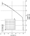
- MEA was dipped in 2 M KOH solution to test its LSV electrochemical activity as below. The scan voltage ranged from 1.0 V to 2.0 V and the scan rate was 50 mV/s.
- the current versus voltage curve of MEA is shown in Fig. 10 .
- the comparison between the current versus voltage curves of Example 6-1, Example 6-2, Example 6-3, and Example 7 is shown in Fig. 11 . As shown in the comparison, only one electrode (e.g.
- anode or cathode adopting the metal-nickel foam could improve the hydrogen evolution efficiency of MEA and omit the flow channel layer on one side of MEA. If both the anode and the cathode adopted metal-nickel foam, the hydrogen evolution efficiency of MEA could be further improved, and the flow channel layers on both sides of MEA could be omitted.
Landscapes
- Chemical & Material Sciences (AREA)
- Engineering & Computer Science (AREA)
- Chemical Kinetics & Catalysis (AREA)
- Electrochemistry (AREA)
- Materials Engineering (AREA)
- Metallurgy (AREA)
- Organic Chemistry (AREA)
- Inorganic Chemistry (AREA)
- Catalysts (AREA)
- Electrolytic Production Of Non-Metals, Compounds, Apparatuses Therefor (AREA)
- Electrodes For Compound Or Non-Metal Manufacture (AREA)
Abstract
Description
- The technical field relates to membrane electrode assembly, and in particular it relates to method for hydrogen evolution by electrolysis with the membrane electrode assembly.
- Seeking alternative energy is imperative now due to energy shortages, and hydrogen energy is the best choice. Hydrogen gas serving as fuel meets the requirements of environmental protection, and electrolysis of water is the easiest way to generate hydrogen and oxygen. In the future development of green hydrogen source technologies for carbon neutrality, the hydrogen evolution by electrolysis of alkaline water has the advantages of low construction cost and long component durability, thereby being a promising technology and attracting international attention.
- The use of clean renewable energy is an international future development trend. The current focus of global development is on improving the efficiency of renewable energy, especially surplus power. Hydrogen evolution by electrolysis of water is beneficial to regulating the excess surplus electricity of renewable electricity. Therefore, improving the cost and efficiency of hydrogen evolution by electrolysis of water is an important basis of the industrialization of future technologies. Efficiently integrating various components to improve electrolysis efficiency and reduce costs is the critical core. Conventional electrolysis needs a flow channel layer to import alkaline aqueous solution and export the hydrogen and oxygen generated by electrolysis. However, the flow channel layer is manufactured by mechanical processing, which is expensive and increases the cost of electrolysis. Accordingly, a novel membrane electrode assembly is called for to omit the flow channel layer.
- One embodiment of the disclosure provides a membrane electrode assembly, including: a first electrode; a second electrode; and an anion exchange membrane disposed between the first electrode and the second electrode. The first electrode includes a first metal mesh; a first catalyst layer wrapping the first metal mesh; a second metal mesh; and a second catalyst layer wrapping the second metal mesh, wherein the first metal mesh is disposed between the anion exchange membrane and the second metal mesh, wherein the second metal mesh is thicker than the first metal mesh, the first catalyst layer is thicker than the second catalyst layer, the second catalyst layer is iron, cobalt, manganese, zinc, niobium, molybdenum, ruthenium, platinum, gold, or aluminum, and the second catalyst layer is crystalline.
- One embodiment of the disclosure provides a method for hydrogen evolution by electrolysis, including: dipping a membrane electrode assembly in an alkaline aqueous solution, wherein the membrane electrode assembly includes: a first electrode; a second electrode; and an anion exchange membrane disposed between the first electrode and the second electrode. The first electrode includes a first metal mesh; a first catalyst layer wrapping the first metal mesh; a second metal mesh; and a second catalyst layer wrapping the second metal mesh, wherein the first metal mesh is disposed between the anion exchange membrane and the second metal mesh, wherein the second metal mesh is thicker than the first metal mesh, the first catalyst layer is thicker than the second catalyst layer, the second catalyst layer is iron, cobalt, manganese, zinc, niobium, molybdenum, ruthenium, platinum, gold, or aluminum, and the second catalyst layer is crystalline. The method also includes applying a potential to the first electrode and the second electrode to electrolyze the alkaline aqueous solution for generating hydrogen with either the first electrode or the second electrode, and generating oxygen with the other electrode, either the first electrode or the second electrode.
- A detailed description is given in the following embodiments with reference to the accompanying drawings.
- The disclosure can be more fully understood by reading the subsequent detailed description and examples with references made to the accompanying drawings, wherein:
-
Fig. 1 shows an electrolysis device for hydrogen evolution. -
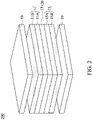
Fig. 2 shows an electrolysis device for hydrogen evolution. -
Fig. 3 shows OER curves of Fe-nickel foams formed from iron precursor solutions of different concentrations in one embodiment. -
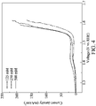
Fig. 4 shows OER curves of Co-nickel foams formed from cobalt precursor solutions of different concentrations in one embodiment. -
Fig. 5 shows HER curves of Co-nickel foams formed from cobalt precursor solutions of different concentrations in one embodiment. -
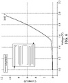
Fig. 6 shows a current versus voltage curve of membrane electrode assemblies in one embodiment. -
Fig. 7 shows a current versus voltage curve of membrane electrode assemblies in one embodiment. -
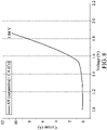
Fig. 8 shows a current versus voltage curve of membrane electrode assemblies in one embodiment. -
Fig. 9 shows current versus voltage curves of membrane electrode assemblies after being operated for 60 hours in one embodiment. -
Fig. 10 shows a current versus voltage curve of membrane electrode assemblies in one embodiment. -
Fig. 11 shows a comparison between current versus voltage curves of the different membrane electrode assemblies. - In the following detailed description, for purposes of explanation, numerous specific details are set forth in order to provide a thorough understanding of the disclosed embodiments. It will be apparent, however, that one or more embodiments may be practiced without these specific details. In other instances, well-known structures and devices are schematically shown in order to simplify the drawing.
- One embodiment of the disclosure provides an
electrolysis device 100 for hydrogen evolution, as shown inFig. 1 . Ananion exchange membrane 13 is disposed between ananode 11 and acathode 15 to form a membrane electrode assembly (MEA) 10, andMEA 10 is disposed between twocurrent collectors 19. For importing reactants (such as an alkaline aqueous solution) to MEA 10 and exporting products (such as hydrogen and oxygen) from MEA 10, oneflow channel layer 17 should be disposed between thecurrent collector 19 and theanode 11, and another oneflow channel layer 17 should be disposed between thecurrent collector 19 and thecathode 15. In general, the manufacture cost of theflow channel layer 17 is high, thereby increasing the cost ofelectrolysis device 100 for hydrogen evolution. - For addressing the flow channel layer issue, one embodiment of the disclosure provides an
electrolysis device 200 for hydrogen evolution, as shown inFig. 2 . Theelectrolysis device 200 for hydrogen evolution includes MEA 20 disposed between twocurrent collectors 19. MEA 20 includes ananode 11, acathode 15, and ananionic exchange membrane 13 disposed between theanode 11 and thecathode 15. Theanode 11 includes ametal mesh 11A wrapped by a catalyst layer C1 (not shown) and ametal mesh 11B wrapped by a catalyst layer C2 (not shown). Themetal mesh 11A is disposed between theanion exchange membrane 13 and themetal mesh 11B. For example, themetal mesh 11A can be stainless steel mesh, Ti mesh, Ni mesh, Ni alloy mesh, niobium alloy mesh, copper mesh, or aluminum mesh. The catalyst layer C1 has a chemical structure of M'aM"bN2, M'cM"dCe, or MxRuyN2, wherein M' is Ni, Co, Fe, Mn, Cr, V, Ti, Cu, or Zn, M" is Nb, Ta, or a combination thereof, M is Ni, Co, Fe, Mn, Cr, V, Ti, Cu, or Zn, 0.7≤a≤1.7, 0.3≤b≤1.3, a+b=2, 0.24≤c≤1.7, 0.3≤d≤1.76, 0.38≤e≤3.61, 0<x<1.3, 0.7<y<2, and x+y=2, wherein M'aM"bN2 is a cubic crystal system, M'cM"dCe is a cubic crystal system or amorphous, and MxRuyN2 is a cubic crystal system or amorphous. Themetal mesh 11A wrapped by the catalyst layer C1 can be referred toTaiwan Patent No. 1677596 - On the other hand, the
metal mesh 11B can be stainless steel mesh, Ti mesh, Ni mesh, Ni alloy mesh, niobium alloy mesh, copper mesh, or aluminum mesh. The catalyst layer C2 is iron, cobalt, manganese, zinc, niobium, molybdenum, ruthenium, platinum, gold, or aluminum. In one embodiment, the catalyst C2 wrapping themeal mesh 11B is iron, cobalt, zinc, niobium, molybdenum, ruthenium, platinum, or gold. Because themetal mesh 11B wrapped by the catalyst layer C2 is formed by chemical reduction, such that the catalyst layer C2 is crystalline. As known from experiments, the crystalline catalyst layer C2 has a better effect of hydrogen evolution by electrolysis than that of the amorphous catalyst C2. In addition, themetal mesh 11B is thicker than themetal mesh 11A so as to replace the function of the flow channel layer. In one embodiment, themetal mesh 11A is a stainless steel mesh with a smooth surface, and themetal mesh 11B is a nickel mesh with a rough surface (e.g. nickel foam). Themetal mesh 11A may protect theanion exchange membrane 13 from being pierced by themetal mesh 11B (the piercedanion exchange membrane 13 may result in short failure of the device). Themetal mesh 11B may replace the expensive flow channel layer, and provide a better effect of hydrogen evolution by electrolysis than that of the flow channel layer. On the other hand, the catalyst layer C1 is thicker than the catalyst layer C2. The catalyst layer C1 may have a thickness of 0.25 micrometers to 1 micrometers, and the catalyst layer C2 may have a thickness of 0.01 micrometers to 0.25 micrometers. If the catalyst layer C1 has a thickness of less than or equal to that of the catalyst layer C2, the effect of hydrogen evolution by electrolysis will be poor. - As shown in
Fig. 2 , thecathode 15 includes ametal mesh 15A wrapped by a catalyst layer C3 (not shown) and ametal mesh 15B wrapped by a catalyst layer C4 (not shown). Themetal mesh 15A is disposed between theanion exchange membrane 13 and themetal mesh 15B. For example, themetal mesh 15A can be stainless steel mesh, Ti mesh, Ni mesh, Ni alloy mesh, niobium alloy mesh, copper mesh, or aluminum mesh. The catalyst layer C3 has a chemical structure of MxRuyN2 or MxRuy, M is Ni, Co, Fe, Mn, Cr, V, Ti, Cu, or Zn, 0<x<1.3, 0.7<y<2, x+y=2, MxRuyN2 is a cubic crystal system or amorphous, and MxRuy is a cubic crystal system. Themetal mesh 15A wrapped by the catalyst layer C3 can be referred toTaiwan Patent No. 1677596 - On the other hand, the
metal mesh 15B can be stainless steel mesh, Ti mesh, Ni mesh, Ni alloy mesh, niobium alloy mesh, copper mesh, or aluminum mesh. The catalyst layer C4 is iron, cobalt, manganese, zinc, niobium, molybdenum, ruthenium, platinum, gold, or aluminum. In one embodiment, the catalyst C4 wrapping themetal mesh 15B is iron, cobalt, manganese, zinc, niobium, molybdenum, gold, or aluminum. Because themetal mesh 15B wrapped by the catalyst layer C4 is formed by chemical reduction, such that the catalyst layer C4 is crystalline. As known from experiments, the crystalline catalyst layer C4 has a better effect of hydrogen evolution by electrolysis than that of the amorphous catalyst C4. In addition, themetal mesh 15B is thicker than themetal mesh 15A so as to replace the function of the flow channel layer. In one embodiment, themetal mesh 15A is a stainless steel mesh with a smooth surface, and themetal mesh 15B is a nickel mesh with a rough surface (e.g. nickel foam). Themetal mesh 15A may protect theanion exchange membrane 13 from being pierced by themetal mesh 15B (the piercedanion exchange membrane 13 may result in short failure of the device). Themetal mesh 15B may replace the expensive flow channel layer, and provide a better effect of hydrogen evolution by electrolysis than that of the flow channel layer. On the other hand, the catalyst layer C3 is thicker than the catalyst layer C4. The catalyst layer C3 may have a thickness of 10 micrometers to 100 micrometers, and the catalyst layer C4 may have a thickness of 0.01 micrometers to 0.25 micrometers. If the catalyst layer C3 has a thickness of less than or equal to that of the catalyst layer C4, the effect of hydrogen evolution by electrolysis will be poor. - In one embodiment, the
anion exchange film 13 can be a halogen ion-containing imidazole polymer or other suitable materials. For example, theanion exchange film 13 can be FAS (commercially available from Fumatech) or X37-50 (commercially available from Dioxide materials). BecauseMEA 20 is used to generate hydrogen by electrolyzing alkaline aqueous solution, theanion exchange film 13 rather than other ionic exchange film is adopted. In some embodiments, the current collectors can be stainless steel plate, titanium plate, or another suitable plate. - Because the
metal mesh 11B of theanode 11 and themetal mesh 15B of thecathode 15 may function as the flow channel layer, there is no additional flow channel layer is required betweenMEA 20 and thecurrent collectors 19. Note that both theanode 11 and thecathode 15 inFig. 2 adopt the design of the dual-layered metal meshes, but the disclosure is not limited thereto. For example, the anode can be another commercially available anode (non-metal mesh) to collocate with the flow channel layer, and only the cathode utilizes the design of the dual-layered metal meshes to omit the flow channel layer. On the other hand, the cathode can be another commercially available cathode (non-metal mesh) to collocate with the flow channel layer, and only the anode utilizes the design of the dual-layered metal meshes to omit the flow channel layer. In other words, only one side of MEA may utilize the dual-layered metal meshes to omit the flow channel layer, and the other side of MEA may utilize the conventional flow channel layer. - In some embodiments, the catalyst layer C1 has a thickness of 0.25 micrometers to 1 micrometer, and the catalyst layer C3 has a thickness of 10 micrometers to 100 micrometers. If the catalyst layer C1 or the catalyst layer C3 is too thin, the effect of hydrogen evolution by electrolysis will be poor. If the catalyst layer C1 or the catalyst layer C3 is too thick, the effect of hydrogen evolution by electrolysis will be poor. In some embodiments, the catalyst layer C2 (or the catalyst layer C4) has a thickness of 0.01 micrometers to 0.25 micrometers. If the catalyst layer C2 or the catalyst layer C4 is too thin, the effect will be similar to that without the catalyst layer. If the catalyst layer C2 or the catalyst layer C4 is too thick, the effect of hydrogen evolution by electrolysis of MEA will be lowered.
- In some embodiments, the
metal mesh 11B or themetal mesh 15B has a pore size of 60 micrometers to 120 micrometers. If the pore size of themetal mesh 11B or themetal mesh 15B is too small, the reactants such as the alkaline aqueous solution cannot be efficiently imported toMEA 20 or the gaseous products (such as hydrogen and oxygen) cannot be efficiently exported fromMEA 20. If the pore size of themetal mesh 11B or themetal mesh 15B is too large, the efficiency of hydrogen evolution by electrolysis cannot be kept for a long period (e.g. the decay extent after being a long-term operation would be high). - In some embodiments, the
metal mesh 11B and the catalyst layer C2 have a weight ratio of 90:10 to 99.9:0.1, or themetal mesh 15B and the catalyst layer C4 have a weight ratio of 90:10 to 99.9:0.1. If the above weight ratio is too low (e.g. the catalyst layer amount is too high), the efficiency of hydrogen evolution by electrolysis will be poor. If the above weight ratio is too high (e.g. the catalyst layer amount is too low), the effect will be similar to that without the catalyst layer. - In some embodiments, the
metal mesh 11B wrapped by the catalyst layer C2 is the same as themetal mesh 15B wrapped by the catalyst layer C4. Alternatively, themetal mesh 11B wrapped by the catalyst layer C2 is different from themetal mesh 15B wrapped by the catalyst layer C4, such as different catalyst types, different pore sizes of the metal meshes, different thickness of the metal meshes, or a combination thereof. For example, the catalyst layer C2 wrapping themetal mesh 11B may adopt iron, and the catalyst layer C4 wrapping themetal mesh 15B may adopt cobalt or gold. - One embodiment of the disclosure provides a method for hydrogen evolution by electrolysis, including: dipping
MEA 20 in an alkaline aqueous solution.MEA 20 is similar to those described above, and the detail is not repeated here. Subsequently, a potential is applied to theanode 11 and thecathode 15 to electrolyze the alkaline aqueous solution for generating hydrogen using thecathode 15 and generating oxygen using theanode 11. In one embodiment, the alkaline aqueous solution has a pH value that is greater than or equal to 13. If the pH value of the alkaline aqueous solution is too low, its conductivity will be poor. In one embodiment, the alkaline aqueous solution has a pH value of 14. - Below, exemplary embodiments will be described in detail with reference to accompanying drawings so as to be easily realized by a person having ordinary knowledge in the art. The inventive concept may be embodied in various forms without being limited to the exemplary embodiments set forth herein. Descriptions of well-known parts are omitted for clarity, and like reference numerals refer to like elements throughout.
- Commercially available nickel foam (GF28024657 commercially available from Merck) was pre-treated by the following steps: (1) dipped in acetone to be ultrasonic vibrated for 15 minutes; (2) washed with de-ionized water for 10 minutes; (3) dipped in 10 wt% of HCl and ultrasonic vibrated and washed for 30 minutes and then washed with water; and (4) dried in a vacuum oven at 50°C. After the pre-treatment, 250 mM of metal precursor solutions of Fe, Co, Mn, Zn, Nb, Mo, Cu, Ru, Pt, Au, Al, and Cr were formulated, respectively. The pre-treated nickel foam was dipped in the metal precursor solution and stirred for 3 hours, and the nickel foam surface was then washed with de-ionized water until the seepage liquid being transparent. The extra water was removed from the nickel foam by wipe paper, and the nickel foam was dried in a hot air circulation oven at 90°C, thereby obtaining a metal-nickel foam sample. As shown in the diffraction pattern of the transmission electron microscope (TEM), the metal of the samples had a crystalline phase. Note that the method of wrapping the nickel foam by the metal belongs to chemical reduction, thereby forming the metal of crystalline phase. If another method such as electroplating was adopted, the metal formed on the nickel foam would not be the crystalline phase. The half-cell electrochemical performance was measured by the following steps. In 0.1 M KOH solution, Ag/AgCl served as a reference electrode to measure EIS and LSV of OER (oxygen evolution reaction) and HER (hydrogen evolution reaction). In EIS measurement, the scan range of OER and HER was 0.1 Hz to 10000 Hz. In LSV measurement of OER, the scan voltage ranged from 1.0 V to 2.0 V, the scan rate was 10 mV/s, and there were three scans. In LSV measurement of HER, the scan voltage ranged from 0 to -0.4 V, the scan rate was 10 mV/s, and there were three scans.
Table 1 HER activity (mV at 10 mA/cm2) OER activity (mV of 100 mA/cm2) Nickel foam 188 349 Fe-nickel foam 160 272 Co-nickel foam 147 337 Mn-nickel foam 162 360 Zn-nickel foam 158 305 Nb-nickel foam 164 320 Mo-nickel foam 168 342 Cu-nickel foam Not detectable 353 Ru-nickel foam Not detectable 324 Pt-nickel foam Not detectable 338 Au-nickel foam 132 330 Al-nickel foam 184 351 Cr-nickel foam 209 368 - For the non-noble metals, the Co-nickel foam had the best HER performance, which had an overpotential of 147 mV at the current density of 10 mA/cm2, as shown in Table 1. For the noble metals, the Au-nickel foam had the best HER performance, which had an overpotential of 132 mV at the current density of 10 mA/cm2. In the OER reactions, the Fe-nickel foam had the lowest overpotential of 272 mV at the current density of 100 mA/cm2.
- The concentrations of the metal precursor solutions of Fe, Co, Mn, Zn, Nb, Mo, Cu, Ru, Pt, Au, Al, and Cr were adjusted, respectively. The pre-treated nickel foam was dipped in the metal precursor solution and stirred for 3 hours, and the nickel foam surface was then washed with de-ionized water until the seepage liquid being transparent. The extra water was removed from the nickel foam by wipe paper, and the nickel foam was dried in a hot air circulation oven at 90°C, thereby obtaining a metal-nickel foam sample. The wrapping amounts on the nickel foams, HER activities, and OER activities of the different metals are shown in Tables 2 and 3, and HER activities and OER activities were measured by the method described above.
Table 2 Metal for HER/ (Nickel foam + Metal) (wt%) HER activity (mV at 10 mA/cm2) 1st 2nd 3rd average Fe 2.34 1.53 2.14 2.00 160 Co 5.26 6.07 4.76 5.36 146 Mn 1.06 2.27 0.00 1.11 162 Cu 77.86 84.56 79.45 80.62 Not detectable Zn 5.88 9.96 2.54 6.13 158 Nb 0.12 0.32 0.05 0.17 164 Mo 1.99 1.85 2.32 2.05 168 Ru 77.79 60.38 72.92 70.36 Not detectable Pt 59.33 70.23 89.02 72.86 Not detectable Au 25.36 33.93 33.93 31.07 132 Table3 Metal for OER / (Nickel foam + Metal) (at%) OER activity (mV at 100 mA/cm2) 1st 2nd 3rd average Fe 2.45 1.61 2.25 2.10 272 Co 5.23 6.04 4.74 5.34 337 Mn 1.12 2.40 0.00 1.17 360 Cu 76.46 83.50 78.12 79.36 353 Zn 5.30 9.06 2.29 5.55 305 Nb 0.075 0.211 0.038 0.11 320 Mo 1.24 1.15 1.46 1.28 342 Ru 67.05 46.96 61.00 58.34 324 Pt 30.50 41.52 70.94 47.66 338 Au 9.19 13.27 13.27 11.91 330 - The amounts of the metals wrapping the nickel foams were low (e.g. less than or equal to 10 wt% or at%) enough to achieve sufficient HER activity or OER activity, as shown in Tables 2 and 3.
- The pre-treated nickel foams were dipped in iron precursor solutions of different concentrations, respectively, and stirred for 3 hours. The nickel foam surface was then washed with de-ionized water until the seepage liquid being transparent. The extra water was removed from the nickel foams by wipe paper, and the nickel foams were dried in a hot air circulation oven at 90°C, thereby obtaining iron-nickel foam samples. The iron-nickel foam samples formed from the iron precursor solutions of different concentrations were measured by energy dispersive X-ray to perform an elemental analysis. HER activities and OER activities of the different iron-nickel foam samples were measured as tabulated in Table 4, which were measured by the method described above. In addition, the OER curves of the iron-nickel foams formed from the iron precursor solutions of different concentrations are shown in
Fig. 3 , the horizontal axis inFig. 3 is the voltage (V) relative to the reversible hydrogen electrode (RHE), and the vertical axis inFig. 3 is the current density (J, mA/cm2). As shown in Table 4, the nickel foam wrapped by a small amount of iron had effects of improving HER and OER.Table 4 [FeCl3] 0.08 mM 0.4 mM 2 mM 10 mM 50 mM 250 mM Fe/Fe + Nickel foam (wt%) 0.04 Not detectable 0.09 0.09 0.22 0.26 HER activity (mV at 10 mA/cm2) Not available Not available Not available Not available Not available 160 OER activity (mV at 100 mA/cm2) 382 326 299 288 281 272 - The pre-treated nickel foams were dipped in cobalt precursor solutions of different concentrations, respectively, and stirred for 3 hours. The nickel foam surface was then washed with de-ionized water until the seepage liquid being transparent. The extra water was removed from the nickel foams by wipe paper, and the nickel foams were dried in a hot air circulation oven at 90°C, thereby obtaining cobalt-nickel foam samples. The cobalt-nickel foam samples formed from the cobalt precursor solutions of different concentrations were measured by energy dispersive X-ray to perform an elemental analysis. HER activities and OER activities of the different cobalt-nickel foam samples were measured as tabulated in Table 5, which were measured by the method described above. In addition, the OER curves of the cobalt-nickel foams formed from the cobalt precursor solutions of different concentrations are shown in
Fig. 4 , the horizontal axis inFig. 4 is the voltage (V) relative to the reversible hydrogen electrode (RHE), and the vertical axis inFig. 4 is the current density (J, mA/cm2). The HER curves of the cobalt-nickel foams formed from the cobalt precursor solutions of different concentrations are shown inFig. 5 , the horizontal axis inFig. 5 is the voltage (V) relative to the reversible hydrogen electrode (RHE), and the vertical axis inFig. 5 is the current density (J, mA/cm2). As shown in Table 5, the nickel foam wrapped by a small amount of cobalt had effects of improving HER and OER.Table 5 HER OER [CoCl2] 125 mM 250 mM 500 mM 125mM 250mM 500mM Co/Co + nickel foam (wt %) 1.74 5.26 4.94 1.74 5.23 4.94 Co/Co + nickel foam (wt %) 0.76 6.07 4.13 0.75 6.04 4.09 Co/Co + nickel foam (wt %) 0.74 4.76 3.47 0.73 4.74 3.45 Average of Co/Co + nickel foam (wt %) 1.08 5.36 4.18 1.07 5.34 4.16 Overpotential at 10 mA/cm2 (mV) 233 147 216 305 131 181 Overpotential at 100 mA/cm2 (mV) Not available Not available Not available 363 337 340 - Commercially available PtC was coated on a carbon paper and a nickel foam (pores size was 91 micrometers) to serve as a cathode of HER. Commercially available insoluble anode (IrO2/RuO2-Ti mesh, DSA electrode) and a nickel foam (pores size was 91 micrometers) served as the anode of OER, and an anion exchange film X37-50 (commercially available from Dioxide Materials) was interposed between the PtC of the cathode and the DSA electrode of the anode to obtain a membrane electrode assembly (MEA). MEA was interposed between two stainless current collectors, and then dipped in 2 M KOH solution to test its electrochemical activity. The scan voltage ranged from 1.2 V to 2.2 V and the scan rate was 50 mV/s. The membrane electrode assembly could generate a current of 5.18 A at 2 V. The potential of MEA was controlled at 2 V and continuously operated for 1000 minutes, and the current decay of MEA was about 4.6%.
- The above experiment was repeated but the pore size of the nickel foam was changed to 151 micrometers. The other components of MEA and the method of testing the electrochemical activity were similar to those described above. The membrane electrode assembly could generate a current of 5.42 A at 2 V. The potential of MEA was controlled at 2 V and continuously operated for 1000 minutes, and the current decay of MEA was about 26.2%.
- The above experiment was repeated but the pore size of the nickel foam was changed to 219 micrometers. The other components of MEA and the method of testing the electrochemical activity were similar to those described above. The membrane electrode assembly could generate a current of 5.63 A at 2 V. The potential of MEA was controlled at 2 V and continuously operated for 1000 minutes, and the current decay of MEA was about 22.4%. As known from the experiments, if the pore size of the nickel foam was too large, the decay extent of MEA after being a long-term operation would be high.
- Ni0.065Ru1.935 catalyst was prepared on the conductive carbon paper as Preparation Examples 2 and 12 in
Taiwan Patent No. 1677596 Taiwan Patent No. 1677596 Fig. 6 . - Example 6-2 was similar to Example 6-1, and the differences in Example 6-2 were Ni1.5Nb0.5N1-stainless steel mesh and Co-nickel foam (e.g. Example 1) serving as the anode of OER, and the serpentine flow channel layer interposed between the Ni1.5Nb0.5N2-stainles steel mesh and the current collector was omitted. The other components of MEA and the method of testing the electrochemical activity were similar to those described above. The current versus voltage curve of MEA is shown in
Fig. 7 . - Example 6-3 was similar to Example 6-1, and the differences in Example 6-3 were Ni0.75Ru1.25N2-stainless steel mesh and Co-nickel foam (e.g. Example 1) serving as the cathode of HER, and the serpentine flow channel layer interposed between the Ni0.75Ru1.25N2-stainless steel mesh and the current collector was omitted. The other components of MEA and the method of testing the electrochemical activity were similar to those described above. The current versus voltage curve of MEA is shown in
Fig. 8 . - Example 6-4 was similar to Example 6-1, and the differences in Example 6-4 were Ni0.065Ru1.935-conductive carbon paper and different metal-nickel foams (e.g. Example 1) serving as the anodes of HER, Ni1.5Nb0.5N2-stainless steel mesh and different metal-nickel foams (e.g. Example 1) serving as the anodes of OER, the serpentine flow channel layer interposed between the Ni0.065Ru1.935-conductive carbon paper and the current collector was omitted, and the serpentine flow channel layer interposed between the Ni1.5Nb0.5N2-stainless steel mesh and the current collector was omitted. The other components of MEA and the method of testing the electrochemical activity were similar to those described above. The current versus voltage curves of MEAs after being operated for 60 hours are shown in
Fig. 9 . Although the metal-nickel foams in the anode and the cathode were the same in this Example, it should be understood that the metal-nickel foams in the anode and the cathode could be different (e.g. different pore sizes of the nickel foam, different amounts of the metal for wrapping the nickel foam, different types of the metal, or a combination thereof). - Ni0.065Ru1.935-conductive carbon paper of Preparation Examples 11 and 12 in
Taiwan Patent No. 1677596 Taiwan Patent No. 1677596 Fig. 10 . The comparison between the current versus voltage curves of Example 6-1, Example 6-2, Example 6-3, and Example 7 is shown inFig. 11 . As shown in the comparison, only one electrode (e.g. anode or cathode) adopting the metal-nickel foam could improve the hydrogen evolution efficiency of MEA and omit the flow channel layer on one side of MEA. If both the anode and the cathode adopted metal-nickel foam, the hydrogen evolution efficiency of MEA could be further improved, and the flow channel layers on both sides of MEA could be omitted. - It will be apparent to those skilled in the art that various modifications and variations can be made to the disclosed methods and materials. It is intended that the specification and examples be considered as exemplary only, with the true scope of the disclosure being indicated by the following claims and their equivalents.
Claims (13)
- A membrane electrode assembly (200), comprising:a first electrode (11 or 15);a second electrode (15 or 11); andan anion exchange membrane (13) disposed between the first electrode and the second electrode,wherein the first electrode (11 or 15) comprisesa first metal mesh (11A or 15A);a first catalyst layer wrapping the first metal mesh;a second metal mesh (11B or 15B); anda second catalyst layer wrapping the second metal mesh,wherein the first metal mesh (11A or 15A) is disposed between the anion exchange membrane (13) and the second metal mesh (11B or 15B),wherein the second metal mesh (11B or 15B) is thicker than the first metal mesh (11A or 15A), the first catalyst layer is thicker than the second catalyst layer, the second catalyst layer is iron, cobalt, manganese, zinc, niobium, molybdenum, ruthenium, platinum, gold, or aluminum, and the second catalyst layer is crystalline.
- The membrane electrode assembly (200) as claimed in the previous claim, wherein the first electrode (11 or 15) is an anode (11), the second electrode (15 or 11) is a cathode (15), and the second catalyst layer is iron, cobalt, zinc, niobium, molybdenum, ruthenium, platinum, or gold.
- The membrane electrode assembly (200) as claimed in the previous claim, wherein the first catalyst layer has a chemical structure of M'aM"bN2, M'cM"dCe, or MxRuyN2, wherein M' is Ni, Co, Fe, Mn, Cr, V, Ti, Cu, or Zn, M" is Nb, Ta, or a combination thereof, M is Ni, Co, Fe, Mn, Cr, V, Ti, Cu, or Zn, 0.7≤a≤1.7, 0.3≤b≤1.3, a+b=2, 0.24≤c≤1.7, 0.3≤d≤1.76, 0.38≤e≤3.61, 0<x<1.3, 0.7<y<2, and x+y=2,
wherein M'aM"bN2 is a cubic crystal system, M'cM"dCe is a cubic crystal system or amorphous, and MxRuyN2 is a cubic crystal system or amorphous. - The membrane electrode assembly (200) as claimed in any of the previous claims, wherein the first electrode (11 or 15) is a cathode (15), the second electrode (15 or 11) is anode (11), and the second catalyst layer is iron, cobalt, manganese, zinc, niobium, molybdenum, gold, or aluminum.
- The membrane electrode assembly (200) as claimed in the previous claim, wherein the first catalyst layer has a chemical structure of MxRuyN2 or MxRuy, M is Ni, Co, Fe, Mn, Cr, V, Ti, Cu, or Zn, 0<x<1.3, 0.7<y<2, x+y=2, MxRuyN2 is a cubic crystal system or amorphous, and MxRuy is a cubic crystal system.
- The membrane electrode assembly (200) as claimed in any of the previous claims, wherein the first catalyst layer has a thickness of 0.25 micrometers to 1 micrometers, and the second catalyst layer has a thickness of 0.01 micrometers to 0.25 micrometers.
- The membrane electrode assembly (200) as claimed in any of the previous claims, wherein the second metal mesh (11B or 15B) has a pore size of 60 micrometers to 120 micrometers.
- The membrane electrode assembly (200) as claimed in any of the previous claims, wherein the second metal mesh (11B or 15B) and the second catalyst layer have a weight ratio of 99:10 to 99.9:0.1.
- The membrane electrode assembly (200) as claimed in any of the previous claims, being interposed between a first current collector (19) and a second current collector (19), wherein the first electrode (11 or 15) is disposed between the anion exchange membrane (13) and the first current collector (19), the second electrode (15 or 11) is disposed between the anion exchange membrane (13) and the second current collector (19), and the first electrode (11 or 15) and the first current collector (19) have no flow channel layer therebetween.
- The membrane electrode assembly (200) as claimed in any of the previous claims, wherein the second electrode (15 or 11) comprises:a third metal mesh (15A or 11A);a third catalyst layer wrapping the third metal mesh (15A or 11A);a fourth metal mesh (15B or 11B); anda fourth catalyst layer wrapping the fourth metal mesh (15B or 11B),wherein the third metal mesh (15A or 11A) is disposed between the anion exchange membrane (13) and the fourth metal mesh (15B or 11B),wherein the fourth metal mesh (15B or 11B) is thicker than the third metal mesh (15A or 11 A), the third catalyst layer is thicker than the fourth catalyst layer, the fourth catalyst layer is iron, cobalt, manganese, zinc, niobium, molybdenum, ruthenium, platinum, gold, or aluminum, and the fourth catalyst layer is crystalline.
- The membrane electrode assembly as claimed in the previous claim, being interposed between a first current collector (19) and a second current collector (19), wherein the first electrode (11 or 15) is disposed between the anion exchange membrane (13) and the first current collector (19), the second electrode (15 or 11) is disposed between the anion exchange membrane (13) and the second current collector (19), the first electrode (11 or 15) and the first current collector (19) have no flow channel layer therebetween, and the second electrode (15 or 11) and the second current collector (19) have no flow channel layer therebetween.
- A method for hydrogen evolution by electrolysis, comprising:dipping a membrane electrode assembly (200) in an alkaline aqueous solution, wherein the membrane electrode assembly (200) comprises:a first electrode (11 or 15);a second electrode (15 or 11); andan anion exchange membrane (13) disposed between the first electrode (11 or 15) and the second electrode (15 or 11),wherein the first electrode (11 or 15) comprisesa first metal mesh (11A or 15A);a first catalyst layer wrapping the first metal mesh (11A or 15A);a second metal mesh (11B or 15B); anda second catalyst layer wrapping the second metal mesh (11B or 15B),wherein the first metal mesh (11A or 15A) is disposed between the anion exchange membrane (13) and the second metal mesh (11B or 15B),wherein the second metal mesh (11B or 15B) is thicker than the first metal mesh (11A or 15A), the first catalyst layer is thicker than the second catalyst layer, the second catalyst layer is iron, cobalt, manganese, zinc, niobium, molybdenum, ruthenium, platinum, gold, or aluminum, and the second catalyst layer is crystalline; andapplying a potential to the first electrode (11 or 15) and the second electrode (15 or 11) to electrolyze the alkaline aqueous solution for generating hydrogen with the first electrode (11 or 15) or the second electrode (15 or 11) and generating oxygen with the other of the first electrode (11 or 15) or the second electrode (15 or 11).
- The method for hydrogen evolution by electrolysis as claimed in the previous claim, wherein the alkaline aqueous solution has a pH value that is greater than or equal to 13.
Applications Claiming Priority (1)
| Application Number | Priority Date | Filing Date | Title |
|---|---|---|---|
| TW110115289A TWI762288B (en) | 2021-04-28 | 2021-04-28 | Membrane electrode assembly and method for hydrogen evolution by electrolysis |
Publications (2)
| Publication Number | Publication Date |
|---|---|
| EP4083259A1 true EP4083259A1 (en) | 2022-11-02 |
| EP4083259B1 EP4083259B1 (en) | 2024-08-21 |
Family
ID=77518959
Family Applications (1)
| Application Number | Title | Priority Date | Filing Date |
|---|---|---|---|
| EP21193172.0A Active EP4083259B1 (en) | 2021-04-28 | 2021-08-26 | Membrane electrode assembly and method for hydrogen evolution by electrolysis |
Country Status (3)
| Country | Link |
|---|---|
| EP (1) | EP4083259B1 (en) |
| JP (1) | JP7178468B2 (en) |
| TW (1) | TWI762288B (en) |
Cited By (1)
| Publication number | Priority date | Publication date | Assignee | Title |
|---|---|---|---|---|
| EP4567153A1 (en) * | 2023-12-04 | 2025-06-11 | Electrogenos Ltd | Catalytic coating |
Families Citing this family (1)
| Publication number | Priority date | Publication date | Assignee | Title |
|---|---|---|---|---|
| WO2024185392A1 (en) * | 2023-03-07 | 2024-09-12 | 出光興産株式会社 | Method for producing electrode catalyst including nitrogen-containing carbon material and solid-electrolyte electrolytic device |
Citations (3)
| Publication number | Priority date | Publication date | Assignee | Title |
|---|---|---|---|---|
| WO2018037774A1 (en) * | 2016-08-23 | 2018-03-01 | 国立大学法人横浜国立大学 | Cathode, electrolysis cell for producing organic hydride, and organic hydride production method |
| US10461350B2 (en) * | 2016-11-11 | 2019-10-29 | Korea Institute Of Science And Technology | Electrochemical reaction cell enhancing reduction reaction |
| US20200173040A1 (en) * | 2018-11-30 | 2020-06-04 | Industrial Technology Research Institute | Membrane electrode assembly and method for hydrogen evolution by electrolysis |
Family Cites Families (5)
| Publication number | Priority date | Publication date | Assignee | Title |
|---|---|---|---|---|
| CN100495788C (en) * | 2007-09-28 | 2009-06-03 | 哈尔滨工业大学 | Self-respiration type fuel battery membrane electrode and method for producing the same |
| EP3161886B1 (en) | 2014-06-27 | 2019-01-09 | Nuvera Fuel Cells, LLC | Flow fields for use with an electrochemical cell |
| US11142836B2 (en) | 2018-11-29 | 2021-10-12 | Industrial Technology Research Institute | Catalyst material and method for manufacturing the same |
| TWI677596B (en) * | 2018-11-30 | 2019-11-21 | 財團法人工業技術研究院 | Membrane electrode assembly and method for hydrogen evolution by electrolysis |
| JP6818920B2 (en) | 2020-02-12 | 2021-01-27 | 株式会社東芝 | Electrochemical reactor |
-
2021
- 2021-04-28 TW TW110115289A patent/TWI762288B/en active
- 2021-08-26 EP EP21193172.0A patent/EP4083259B1/en active Active
- 2021-10-21 JP JP2021172261A patent/JP7178468B2/en active Active
Patent Citations (3)
| Publication number | Priority date | Publication date | Assignee | Title |
|---|---|---|---|---|
| WO2018037774A1 (en) * | 2016-08-23 | 2018-03-01 | 国立大学法人横浜国立大学 | Cathode, electrolysis cell for producing organic hydride, and organic hydride production method |
| US10461350B2 (en) * | 2016-11-11 | 2019-10-29 | Korea Institute Of Science And Technology | Electrochemical reaction cell enhancing reduction reaction |
| US20200173040A1 (en) * | 2018-11-30 | 2020-06-04 | Industrial Technology Research Institute | Membrane electrode assembly and method for hydrogen evolution by electrolysis |
Cited By (1)
| Publication number | Priority date | Publication date | Assignee | Title |
|---|---|---|---|---|
| EP4567153A1 (en) * | 2023-12-04 | 2025-06-11 | Electrogenos Ltd | Catalytic coating |
Also Published As
| Publication number | Publication date |
|---|---|
| JP7178468B2 (en) | 2022-11-25 |
| JP2022170650A (en) | 2022-11-10 |
| TW202242199A (en) | 2022-11-01 |
| EP4083259B1 (en) | 2024-08-21 |
| TWI762288B (en) | 2022-04-21 |
Similar Documents
| Publication | Publication Date | Title |
|---|---|---|
| Zhu et al. | Multi-scale study on bifunctional Co/Fe–N–C cathode catalyst layers with high active site density for the oxygen reduction reaction | |
| Vincent et al. | Highly cost-effective platinum-free anion exchange membrane electrolysis for large scale energy storage and hydrogen production | |
| Lu et al. | Nickel based catalysts for highly efficient H2 evolution from wastewater in microbial electrolysis cells | |
| KR101726575B1 (en) | Ultra-low Loading of Pt-decorated Ni Electrocatalyst, Manufacturing Method of the Same and Anion Exchange Membrane Water Electrolyzer Using the Same | |
| Vidales et al. | Evaluation of nickel-molybdenum-oxides as cathodes for hydrogen evolution by water electrolysis in acidic, alkaline, and neutral media | |
| US11549188B2 (en) | Membrane electrode assembly and method for hydrogen evolution by electrolysis | |
| CN105780050B (en) | A kind of preparation method for decomposing the doping phosphoric acid group Ni-Fe hydroxide nano film catalysts of water | |
| Cheng et al. | Pd doped Co3O4 nanowire array as the H2O2 electroreduction catalyst | |
| EP4083259B1 (en) | Membrane electrode assembly and method for hydrogen evolution by electrolysis | |
| US11142836B2 (en) | Catalyst material and method for manufacturing the same | |
| US10914012B2 (en) | Membrane electrode assembly and method for hydrogen evolution by electrolysis | |
| US12077873B2 (en) | Method for manufacturing nitride catalyst | |
| Hosseini et al. | RuO2, RuO2–TiO2 and RuO2–TiO2–IrO2 nanoparticles supported on Ni mesh as mixed metal oxide electrodes for oxygen reduction reaction | |
| KR101860763B1 (en) | Non-precious Metal Electrocatalyst, Proton Exchange Membrane Water Electrolyzer Using The Same And Method For Preparing The Same | |
| Park et al. | Ionomer-free Co-Ru based electrode for efficient proton exchange membrane water electrolysis via synergistic catalysis | |
| TWI677596B (en) | Membrane electrode assembly and method for hydrogen evolution by electrolysis | |
| Zhao et al. | Electrodeposition preparation of highly dispersed Pt/HxWO3 composite catalysts for PEMFCs | |
| Mikolajczyk et al. | Influence of electrodeposited Ni-Mo alloy on hydrogen evolution reaction at nickel foam cathode | |
| CN118910646B (en) | Electrolytic water catalyst for PEM with low Ru loading capacity, and preparation method and application thereof | |
| US10914011B2 (en) | Membrane electrode assembly and method for hydrogen evolution by electrolysis | |
| Sabalová et al. | Electrocatalytic hydrogen evolution in acidic media using electrodeposited Ag/PPy and Ni/PPy hybrid materials | |
| Lee et al. | Highly Active and Durable NiMoMn Hydrogen Evolution Catalysts for Proton‐Exchange Membrane Water Electrolysis | |
| Kim et al. | Hydrogen evolving electrode with low Pt loading fabricated by repeated pulse electrodeposition | |
| CN115369443A (en) | Nano-flake Bi-Bi 2 O 3 Preparation method and application of electrocatalyst | |
| CN115341218B (en) | Membrane electrode assembly and method for producing hydrogen by electrolysis |
Legal Events
| Date | Code | Title | Description |
|---|---|---|---|
| PUAI | Public reference made under article 153(3) epc to a published international application that has entered the european phase |
Free format text: ORIGINAL CODE: 0009012 |
|
| STAA | Information on the status of an ep patent application or granted ep patent |
Free format text: STATUS: REQUEST FOR EXAMINATION WAS MADE |
|
| 17P | Request for examination filed |
Effective date: 20220328 |
|
| AK | Designated contracting states |
Kind code of ref document: A1 Designated state(s): AL AT BE BG CH CY CZ DE DK EE ES FI FR GB GR HR HU IE IS IT LI LT LU LV MC MK MT NL NO PL PT RO RS SE SI SK SM TR |
|
| STAA | Information on the status of an ep patent application or granted ep patent |
Free format text: STATUS: EXAMINATION IS IN PROGRESS |
|
| 17Q | First examination report despatched |
Effective date: 20230428 |
|
| GRAP | Despatch of communication of intention to grant a patent |
Free format text: ORIGINAL CODE: EPIDOSNIGR1 |
|
| STAA | Information on the status of an ep patent application or granted ep patent |
Free format text: STATUS: GRANT OF PATENT IS INTENDED |
|
| INTG | Intention to grant announced |
Effective date: 20240322 |
|
| RIN1 | Information on inventor provided before grant (corrected) |
Inventor name: CHEN, HAO-MING Inventor name: TSAI, LI-DUAN Inventor name: HUANG, HSIAO-CHUN Inventor name: LIN, KUO-HSIN |
|
| GRAS | Grant fee paid |
Free format text: ORIGINAL CODE: EPIDOSNIGR3 |
|
| GRAA | (expected) grant |
Free format text: ORIGINAL CODE: 0009210 |
|
| STAA | Information on the status of an ep patent application or granted ep patent |
Free format text: STATUS: THE PATENT HAS BEEN GRANTED |
|
| P01 | Opt-out of the competence of the unified patent court (upc) registered |
Free format text: CASE NUMBER: APP_36631/2024 Effective date: 20240619 |
|
| AK | Designated contracting states |
Kind code of ref document: B1 Designated state(s): AL AT BE BG CH CY CZ DE DK EE ES FI FR GB GR HR HU IE IS IT LI LT LU LV MC MK MT NL NO PL PT RO RS SE SI SK SM TR |
|
| REG | Reference to a national code |
Ref country code: GB Ref legal event code: FG4D |
|
| REG | Reference to a national code |
Ref country code: CH Ref legal event code: EP |
|
| REG | Reference to a national code |
Ref country code: IE Ref legal event code: FG4D |
|
| REG | Reference to a national code |
Ref country code: DE Ref legal event code: R096 Ref document number: 602021017429 Country of ref document: DE |
|
| REG | Reference to a national code |
Ref country code: LT Ref legal event code: MG9D |
|
| REG | Reference to a national code |
Ref country code: NL Ref legal event code: MP Effective date: 20240821 |
|
| PG25 | Lapsed in a contracting state [announced via postgrant information from national office to epo] |
Ref country code: NO Free format text: LAPSE BECAUSE OF FAILURE TO SUBMIT A TRANSLATION OF THE DESCRIPTION OR TO PAY THE FEE WITHIN THE PRESCRIBED TIME-LIMIT Effective date: 20241121 |
|
| REG | Reference to a national code |
Ref country code: AT Ref legal event code: MK05 Ref document number: 1715548 Country of ref document: AT Kind code of ref document: T Effective date: 20240821 |
|
| PG25 | Lapsed in a contracting state [announced via postgrant information from national office to epo] |
Ref country code: PT Free format text: LAPSE BECAUSE OF FAILURE TO SUBMIT A TRANSLATION OF THE DESCRIPTION OR TO PAY THE FEE WITHIN THE PRESCRIBED TIME-LIMIT Effective date: 20241223 Ref country code: NL Free format text: LAPSE BECAUSE OF FAILURE TO SUBMIT A TRANSLATION OF THE DESCRIPTION OR TO PAY THE FEE WITHIN THE PRESCRIBED TIME-LIMIT Effective date: 20240821 Ref country code: PL Free format text: LAPSE BECAUSE OF FAILURE TO SUBMIT A TRANSLATION OF THE DESCRIPTION OR TO PAY THE FEE WITHIN THE PRESCRIBED TIME-LIMIT Effective date: 20240821 Ref country code: GR Free format text: LAPSE BECAUSE OF FAILURE TO SUBMIT A TRANSLATION OF THE DESCRIPTION OR TO PAY THE FEE WITHIN THE PRESCRIBED TIME-LIMIT Effective date: 20241122 Ref country code: FI Free format text: LAPSE BECAUSE OF FAILURE TO SUBMIT A TRANSLATION OF THE DESCRIPTION OR TO PAY THE FEE WITHIN THE PRESCRIBED TIME-LIMIT Effective date: 20240821 |
|
| PG25 | Lapsed in a contracting state [announced via postgrant information from national office to epo] |
Ref country code: BG Free format text: LAPSE BECAUSE OF FAILURE TO SUBMIT A TRANSLATION OF THE DESCRIPTION OR TO PAY THE FEE WITHIN THE PRESCRIBED TIME-LIMIT Effective date: 20240821 |
|
| PG25 | Lapsed in a contracting state [announced via postgrant information from national office to epo] |
Ref country code: LV Free format text: LAPSE BECAUSE OF FAILURE TO SUBMIT A TRANSLATION OF THE DESCRIPTION OR TO PAY THE FEE WITHIN THE PRESCRIBED TIME-LIMIT Effective date: 20240821 |
|
| PG25 | Lapsed in a contracting state [announced via postgrant information from national office to epo] |
Ref country code: AT Free format text: LAPSE BECAUSE OF FAILURE TO SUBMIT A TRANSLATION OF THE DESCRIPTION OR TO PAY THE FEE WITHIN THE PRESCRIBED TIME-LIMIT Effective date: 20240821 Ref country code: IS Free format text: LAPSE BECAUSE OF FAILURE TO SUBMIT A TRANSLATION OF THE DESCRIPTION OR TO PAY THE FEE WITHIN THE PRESCRIBED TIME-LIMIT Effective date: 20241221 |
|
| PG25 | Lapsed in a contracting state [announced via postgrant information from national office to epo] |
Ref country code: HR Free format text: LAPSE BECAUSE OF FAILURE TO SUBMIT A TRANSLATION OF THE DESCRIPTION OR TO PAY THE FEE WITHIN THE PRESCRIBED TIME-LIMIT Effective date: 20240821 |
|
| PG25 | Lapsed in a contracting state [announced via postgrant information from national office to epo] |
Ref country code: RS Free format text: LAPSE BECAUSE OF FAILURE TO SUBMIT A TRANSLATION OF THE DESCRIPTION OR TO PAY THE FEE WITHIN THE PRESCRIBED TIME-LIMIT Effective date: 20241121 Ref country code: ES Free format text: LAPSE BECAUSE OF FAILURE TO SUBMIT A TRANSLATION OF THE DESCRIPTION OR TO PAY THE FEE WITHIN THE PRESCRIBED TIME-LIMIT Effective date: 20240821 |
|
| PG25 | Lapsed in a contracting state [announced via postgrant information from national office to epo] |
Ref country code: RS Free format text: LAPSE BECAUSE OF FAILURE TO SUBMIT A TRANSLATION OF THE DESCRIPTION OR TO PAY THE FEE WITHIN THE PRESCRIBED TIME-LIMIT Effective date: 20241121 Ref country code: PT Free format text: LAPSE BECAUSE OF FAILURE TO SUBMIT A TRANSLATION OF THE DESCRIPTION OR TO PAY THE FEE WITHIN THE PRESCRIBED TIME-LIMIT Effective date: 20241223 Ref country code: PL Free format text: LAPSE BECAUSE OF FAILURE TO SUBMIT A TRANSLATION OF THE DESCRIPTION OR TO PAY THE FEE WITHIN THE PRESCRIBED TIME-LIMIT Effective date: 20240821 Ref country code: NO Free format text: LAPSE BECAUSE OF FAILURE TO SUBMIT A TRANSLATION OF THE DESCRIPTION OR TO PAY THE FEE WITHIN THE PRESCRIBED TIME-LIMIT Effective date: 20241121 Ref country code: NL Free format text: LAPSE BECAUSE OF FAILURE TO SUBMIT A TRANSLATION OF THE DESCRIPTION OR TO PAY THE FEE WITHIN THE PRESCRIBED TIME-LIMIT Effective date: 20240821 Ref country code: LV Free format text: LAPSE BECAUSE OF FAILURE TO SUBMIT A TRANSLATION OF THE DESCRIPTION OR TO PAY THE FEE WITHIN THE PRESCRIBED TIME-LIMIT Effective date: 20240821 Ref country code: IS Free format text: LAPSE BECAUSE OF FAILURE TO SUBMIT A TRANSLATION OF THE DESCRIPTION OR TO PAY THE FEE WITHIN THE PRESCRIBED TIME-LIMIT Effective date: 20241221 Ref country code: HR Free format text: LAPSE BECAUSE OF FAILURE TO SUBMIT A TRANSLATION OF THE DESCRIPTION OR TO PAY THE FEE WITHIN THE PRESCRIBED TIME-LIMIT Effective date: 20240821 Ref country code: GR Free format text: LAPSE BECAUSE OF FAILURE TO SUBMIT A TRANSLATION OF THE DESCRIPTION OR TO PAY THE FEE WITHIN THE PRESCRIBED TIME-LIMIT Effective date: 20241122 Ref country code: FI Free format text: LAPSE BECAUSE OF FAILURE TO SUBMIT A TRANSLATION OF THE DESCRIPTION OR TO PAY THE FEE WITHIN THE PRESCRIBED TIME-LIMIT Effective date: 20240821 Ref country code: ES Free format text: LAPSE BECAUSE OF FAILURE TO SUBMIT A TRANSLATION OF THE DESCRIPTION OR TO PAY THE FEE WITHIN THE PRESCRIBED TIME-LIMIT Effective date: 20240821 Ref country code: BG Free format text: LAPSE BECAUSE OF FAILURE TO SUBMIT A TRANSLATION OF THE DESCRIPTION OR TO PAY THE FEE WITHIN THE PRESCRIBED TIME-LIMIT Effective date: 20240821 Ref country code: AT Free format text: LAPSE BECAUSE OF FAILURE TO SUBMIT A TRANSLATION OF THE DESCRIPTION OR TO PAY THE FEE WITHIN THE PRESCRIBED TIME-LIMIT Effective date: 20240821 |
|
| REG | Reference to a national code |
Ref country code: CH Ref legal event code: PL |
|
| PG25 | Lapsed in a contracting state [announced via postgrant information from national office to epo] |
Ref country code: DK Free format text: LAPSE BECAUSE OF FAILURE TO SUBMIT A TRANSLATION OF THE DESCRIPTION OR TO PAY THE FEE WITHIN THE PRESCRIBED TIME-LIMIT Effective date: 20240821 Ref country code: SM Free format text: LAPSE BECAUSE OF FAILURE TO SUBMIT A TRANSLATION OF THE DESCRIPTION OR TO PAY THE FEE WITHIN THE PRESCRIBED TIME-LIMIT Effective date: 20240821 Ref country code: RO Free format text: LAPSE BECAUSE OF FAILURE TO SUBMIT A TRANSLATION OF THE DESCRIPTION OR TO PAY THE FEE WITHIN THE PRESCRIBED TIME-LIMIT Effective date: 20240821 |
|
| PG25 | Lapsed in a contracting state [announced via postgrant information from national office to epo] |
Ref country code: LU Free format text: LAPSE BECAUSE OF NON-PAYMENT OF DUE FEES Effective date: 20240826 |
|
| PG25 | Lapsed in a contracting state [announced via postgrant information from national office to epo] |
Ref country code: CH Free format text: LAPSE BECAUSE OF NON-PAYMENT OF DUE FEES Effective date: 20240831 Ref country code: EE Free format text: LAPSE BECAUSE OF FAILURE TO SUBMIT A TRANSLATION OF THE DESCRIPTION OR TO PAY THE FEE WITHIN THE PRESCRIBED TIME-LIMIT Effective date: 20240821 |
|
| PG25 | Lapsed in a contracting state [announced via postgrant information from national office to epo] |
Ref country code: CZ Free format text: LAPSE BECAUSE OF FAILURE TO SUBMIT A TRANSLATION OF THE DESCRIPTION OR TO PAY THE FEE WITHIN THE PRESCRIBED TIME-LIMIT Effective date: 20240821 |
|
| PG25 | Lapsed in a contracting state [announced via postgrant information from national office to epo] |
Ref country code: IT Free format text: LAPSE BECAUSE OF FAILURE TO SUBMIT A TRANSLATION OF THE DESCRIPTION OR TO PAY THE FEE WITHIN THE PRESCRIBED TIME-LIMIT Effective date: 20240821 Ref country code: SK Free format text: LAPSE BECAUSE OF FAILURE TO SUBMIT A TRANSLATION OF THE DESCRIPTION OR TO PAY THE FEE WITHIN THE PRESCRIBED TIME-LIMIT Effective date: 20240821 |
|
| REG | Reference to a national code |
Ref country code: DE Ref legal event code: R097 Ref document number: 602021017429 Country of ref document: DE |
|
| REG | Reference to a national code |
Ref country code: BE Ref legal event code: MM Effective date: 20240831 |
|
| PLBE | No opposition filed within time limit |
Free format text: ORIGINAL CODE: 0009261 |
|
| STAA | Information on the status of an ep patent application or granted ep patent |
Free format text: STATUS: NO OPPOSITION FILED WITHIN TIME LIMIT |
|
| PG25 | Lapsed in a contracting state [announced via postgrant information from national office to epo] |
Ref country code: MC Free format text: LAPSE BECAUSE OF FAILURE TO SUBMIT A TRANSLATION OF THE DESCRIPTION OR TO PAY THE FEE WITHIN THE PRESCRIBED TIME-LIMIT Effective date: 20240821 |
|
| PG25 | Lapsed in a contracting state [announced via postgrant information from national office to epo] |
Ref country code: BE Free format text: LAPSE BECAUSE OF NON-PAYMENT OF DUE FEES Effective date: 20240831 |
|
| PG25 | Lapsed in a contracting state [announced via postgrant information from national office to epo] |
Ref country code: IE Free format text: LAPSE BECAUSE OF NON-PAYMENT OF DUE FEES Effective date: 20240826 |
|
| 26N | No opposition filed |
Effective date: 20250522 |
|
| PG25 | Lapsed in a contracting state [announced via postgrant information from national office to epo] |
Ref country code: SE Free format text: LAPSE BECAUSE OF FAILURE TO SUBMIT A TRANSLATION OF THE DESCRIPTION OR TO PAY THE FEE WITHIN THE PRESCRIBED TIME-LIMIT Effective date: 20240821 |
|
| PGFP | Annual fee paid to national office [announced via postgrant information from national office to epo] |
Ref country code: DE Payment date: 20250827 Year of fee payment: 5 |
|
| PGFP | Annual fee paid to national office [announced via postgrant information from national office to epo] |
Ref country code: GB Payment date: 20250827 Year of fee payment: 5 |
|
| PGFP | Annual fee paid to national office [announced via postgrant information from national office to epo] |
Ref country code: FR Payment date: 20250825 Year of fee payment: 5 |
|
| PG25 | Lapsed in a contracting state [announced via postgrant information from national office to epo] |
Ref country code: CY Free format text: LAPSE BECAUSE OF FAILURE TO SUBMIT A TRANSLATION OF THE DESCRIPTION OR TO PAY THE FEE WITHIN THE PRESCRIBED TIME-LIMIT; INVALID AB INITIO Effective date: 20210826 |
|
| PG25 | Lapsed in a contracting state [announced via postgrant information from national office to epo] |
Ref country code: HU Free format text: LAPSE BECAUSE OF FAILURE TO SUBMIT A TRANSLATION OF THE DESCRIPTION OR TO PAY THE FEE WITHIN THE PRESCRIBED TIME-LIMIT; INVALID AB INITIO Effective date: 20210826 |