EP4082946A1 - Electronically controlled viscous coupler for combine harvester - Google Patents
Electronically controlled viscous coupler for combine harvester Download PDFInfo
- Publication number
- EP4082946A1 EP4082946A1 EP22169224.7A EP22169224A EP4082946A1 EP 4082946 A1 EP4082946 A1 EP 4082946A1 EP 22169224 A EP22169224 A EP 22169224A EP 4082946 A1 EP4082946 A1 EP 4082946A1
- Authority
- EP
- European Patent Office
- Prior art keywords
- conveyor
- viscous clutch
- grain
- controller
- clutch
- Prior art date
- Legal status (The legal status is an assumption and is not a legal conclusion. Google has not performed a legal analysis and makes no representation as to the accuracy of the status listed.)
- Granted
Links
Images

Classifications
-
- A—HUMAN NECESSITIES
- A01—AGRICULTURE; FORESTRY; ANIMAL HUSBANDRY; HUNTING; TRAPPING; FISHING
- A01F—PROCESSING OF HARVESTED PRODUCE; HAY OR STRAW PRESSES; DEVICES FOR STORING AGRICULTURAL OR HORTICULTURAL PRODUCE
- A01F12/00—Parts or details of threshing apparatus
- A01F12/46—Mechanical grain conveyors
-
- A—HUMAN NECESSITIES
- A01—AGRICULTURE; FORESTRY; ANIMAL HUSBANDRY; HUNTING; TRAPPING; FISHING
- A01D—HARVESTING; MOWING
- A01D41/00—Combines, i.e. harvesters or mowers combined with threshing devices
- A01D41/12—Details of combines
- A01D41/1208—Tanks for grain or chaff
- A01D41/1217—Unloading mechanisms
-
- A—HUMAN NECESSITIES
- A01—AGRICULTURE; FORESTRY; ANIMAL HUSBANDRY; HUNTING; TRAPPING; FISHING
- A01D—HARVESTING; MOWING
- A01D90/00—Vehicles for carrying harvested crops with means for selfloading or unloading
- A01D90/10—Unloading means
-
- B—PERFORMING OPERATIONS; TRANSPORTING
- B65—CONVEYING; PACKING; STORING; HANDLING THIN OR FILAMENTARY MATERIAL
- B65G—TRANSPORT OR STORAGE DEVICES, e.g. CONVEYORS FOR LOADING OR TIPPING, SHOP CONVEYOR SYSTEMS OR PNEUMATIC TUBE CONVEYORS
- B65G33/00—Screw or rotary spiral conveyors
- B65G33/08—Screw or rotary spiral conveyors for fluent solid materials
-
- B—PERFORMING OPERATIONS; TRANSPORTING
- B65—CONVEYING; PACKING; STORING; HANDLING THIN OR FILAMENTARY MATERIAL
- B65G—TRANSPORT OR STORAGE DEVICES, e.g. CONVEYORS FOR LOADING OR TIPPING, SHOP CONVEYOR SYSTEMS OR PNEUMATIC TUBE CONVEYORS
- B65G33/00—Screw or rotary spiral conveyors
- B65G33/24—Details
- B65G33/34—Applications of driving gear
-
- F—MECHANICAL ENGINEERING; LIGHTING; HEATING; WEAPONS; BLASTING
- F16—ENGINEERING ELEMENTS AND UNITS; GENERAL MEASURES FOR PRODUCING AND MAINTAINING EFFECTIVE FUNCTIONING OF MACHINES OR INSTALLATIONS; THERMAL INSULATION IN GENERAL
- F16D—COUPLINGS FOR TRANSMITTING ROTATION; CLUTCHES; BRAKES
- F16D35/00—Fluid clutches in which the clutching is predominantly obtained by fluid adhesion
- F16D35/02—Fluid clutches in which the clutching is predominantly obtained by fluid adhesion with rotary working chambers and rotary reservoirs, e.g. in one coupling part
- F16D35/021—Fluid clutches in which the clutching is predominantly obtained by fluid adhesion with rotary working chambers and rotary reservoirs, e.g. in one coupling part actuated by valves
- F16D35/024—Fluid clutches in which the clutching is predominantly obtained by fluid adhesion with rotary working chambers and rotary reservoirs, e.g. in one coupling part actuated by valves the valve being actuated electrically, e.g. by an electromagnet
-
- F—MECHANICAL ENGINEERING; LIGHTING; HEATING; WEAPONS; BLASTING
- F16—ENGINEERING ELEMENTS AND UNITS; GENERAL MEASURES FOR PRODUCING AND MAINTAINING EFFECTIVE FUNCTIONING OF MACHINES OR INSTALLATIONS; THERMAL INSULATION IN GENERAL
- F16D—COUPLINGS FOR TRANSMITTING ROTATION; CLUTCHES; BRAKES
- F16D35/00—Fluid clutches in which the clutching is predominantly obtained by fluid adhesion
- F16D35/02—Fluid clutches in which the clutching is predominantly obtained by fluid adhesion with rotary working chambers and rotary reservoirs, e.g. in one coupling part
- F16D35/028—Fluid clutches in which the clutching is predominantly obtained by fluid adhesion with rotary working chambers and rotary reservoirs, e.g. in one coupling part actuated electrically, e.g. by an electromagnet
-
- G—PHYSICS
- G05—CONTROLLING; REGULATING
- G05D—SYSTEMS FOR CONTROLLING OR REGULATING NON-ELECTRIC VARIABLES
- G05D9/00—Level control, e.g. controlling quantity of material stored in vessel
- G05D9/12—Level control, e.g. controlling quantity of material stored in vessel characterised by the use of electric means
-
- B—PERFORMING OPERATIONS; TRANSPORTING
- B65—CONVEYING; PACKING; STORING; HANDLING THIN OR FILAMENTARY MATERIAL
- B65G—TRANSPORT OR STORAGE DEVICES, e.g. CONVEYORS FOR LOADING OR TIPPING, SHOP CONVEYOR SYSTEMS OR PNEUMATIC TUBE CONVEYORS
- B65G2811/00—Indexing codes relating to common features for more than one conveyor kind or type
- B65G2811/09—Driving means for the conveyors
- B65G2811/095—Speed variation control means
Definitions
- the present invention relates to an electronically controlled viscous coupler for a mechanical power transmission system, such as a grain unloading system of a combine harvester.
- combine grain tank unloading systems of combine harvesters typically consist of single or multiple apparatus including a cross conveyor or conveyors, that feed grain to an unloader conveyor or conveyors, and a vertical unloader conveyor, such as an auger, operable for lifting the grain to a generally horizontal conveyor or auger that conveys the grain to a truck or other holding bin.
- viscous clutch for use with combine grain tank unloading systems of combine harvesters. It should be understood, however, that the viscous clutch is not limited for use with unloading systems, rather, the viscous clutch is applicable for use with any variable speed (non-zero control) mechanical power transmission system, such as those systems in a combine harvester.
- an apparatus for feeding or conveying grain comprises a conveyor for moving grain having an input end and an output end; and a viscous clutch either directly or indirectly connected to the input end of the conveyor for transmitting torque from an input component to the conveyor in a variable manner.
- a method of feeding or conveying grain using a conveyor in an agricultural vehicle comprising: operating a viscous clutch, which is either directly or indirectly connected to an input end of the conveyor, to transmit torque from an input component to the conveyor in a variable manner.
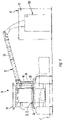
- FIG. 1 a representative agricultural harvesting machine 10 is shown, including an unloader conveyor 12 operable for unloading grain from a grain holding device, which is a conventional grain tank 14, located on an upper region of harvesting machine 10.
- a grain holding device which is a conventional grain tank 14, located on an upper region of harvesting machine 10.
- harvesting machine 10 is depicted as a well-known, commercially available combine operable for harvesting a wide variety of grains, including, but not limited to, wheat, beans, corn, rice, and the like.
- the grain is harvested and threshed from stalks, pods, or other crop material, and conveyed away from a cleaning system of machine 10 by a clean grain conveyor to a grain elevator (not shown).
- unloader conveyor 12 can be operated for unloading the grain from tank 14, onto the ground, or into a wagon, truck or other vehicle, or a bin or other grain receptacle 16 (larger receptacle illustrated for example) or 16A (smaller receptacle).
- grain tank 14 includes apparatus 18 operable for feeding or conveying the grain contained therein to unloader conveyor 12.
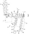
- apparatus 18 includes a pair of conventional cross conveyors 20 and 22 disposed in sideward extending covered troughs 58 in a floor of the grain tank, in the well-known manner.
- Cross conveyors 20 and 22 each comprises a generally horizontal elongate helical auger rotatable by a drive 30 (via a clutch 24) as denoted by the arrows in FIG. 2 , for conveying grain through the respective troughs 58 to an opening 26 in an inlet end 28 of unloader conveyor 12.
- Each conveyor has an input end 20a and an opposite output end 20b.
- apparatus 18 in grain tank 14 is illustrated including two cross conveyors 20 and 22 for feeding grain to unloader conveyor 12
- a variety of other conveyor configurations can be utilized for performing this function, including, but not limited to, a single conveyor, or more than two conveyors, such as two cross conveyors that feed to a main conveyor, which, in turn, feeds the unloader conveyor.
- apparatus 18 can comprise other type conveyors, such as a moving belt or belts, or any other apparatus suitable for feeding grain to the unloader conveyor.
- Unloader conveyor 12 here includes an elongate upwardly or generally vertically extending auger 46 supported for rotation in an upwardly extending tubular housing 48, and an elongate auger 50 oriented horizontally or at a small acute angle to horizontal, supported for rotation in an elongate tubular housing 52 connected to and forming a continuation of housing 48. Housing 52 and an upper portion of housing 48 are supported in cantilever relation by a lower portion of housing 48 for rotation relative thereto, between a sidewardly extending unloading position as shown in FIG. 1 , and a rearwardly extending stowed position at about a 90 degree angle to the unloading position, in the well-known manner.
- Auger 50 is connected to auger 46 for rotation thereby in a suitable manner, such as by bevel gears, a Hooke's joint, or the like, also in the well-known manner. Auger 46 is driven by the drive 30 connected thereto.
- a drive 30 is connected to conveyors 20, 22 and 46 for rotating conveyors in the desired rotational direction.
- Drive 30 may represent an engine, a motor, an electric drive motor, a fluid motor, or a driven shaft that is connected to the motor of the machine 10, for example.
- machine 10 may include multiple independent drives 30 for independently driving conveyors 20, 22 and 46.
- Drive 30 is connected to each of conveyors 20, 22 and 46 via an input component 32a, a viscous clutch 24 and an output component 32b.
- Input component 32a and output component 32b may each be a shaft (such as a PTO shaft), a belt, or a chain, one or more gears, a gear box or a transmission that provides a two-stage reduction in power (for example) for driving the conveyors 20, 22 and 46 at an appropriate speed.
- a separate clutch 24 is associated with each conveyor 20, 22 and 46.
- the output of a single clutch 24 may be connected to all of the conveyors 20, 22 and 46 (or output components 32b) by way of one or more belts, shafts, etc. for simultaneously controlling all of those conveyors 20, 22 and 46.
- Viscous clutch 24 accomplishes variable speed control for each conveyor 20, 22, 46 regardless of the speed transmitted by the input component 32a.
- Each clutch 24 is shown connected to the output side of the input component 32a and the input side of the output component 32b.
- the output side of the output component 32b is either directly or indirectly connected to one of the conveyors 20, 22 and 46.
- each clutch 24 may be connected directly between drive 30 and one of the conveyors 20, 22, 46.
- Machine 10 further comprises a control 34 that is operable for controlling unloader conveyor 12 and apparatus 18.
- Elements of control 34 include a processor based controller 36 that is connected to an input device 38, drive 30 and clutches 24 by suitable conductive paths 44.
- Paths 44 can be, for instance, wires of a wiring harness, or a wired or wireless communications network.
- input device 38 can be located on a multi-function or propulsion handle 60 ( FIG. 3 ) or other location on the machine 10.
- each clutch 24 is an electromagnetically actuated viscous clutch.
- the details of such an exemplary clutch for use with machine 10 are described in U.S. Patent No. 8,100,241 , which is incorporated by reference herein in its entirety and for all purposes.
- the clutch 24 permits selective engagement between input component 32a (connected to drive 30) and output component 32b (connected to one of the conveyors 20, 22, 46), for example, to selectively drive one of the conveyors 20, 22, 46 as a function of a rotational input from the input component 32a.
- rotation of the input component 32a In a closed position of the clutch, rotation of the input component 32a is transmitted to the output component 32b, whereas, in an open position of the clutch, rotation of the input component 32a is not transmitted to the output component 32b.
- Controller 36 is connected to clutches 24 for selectively varying (i.e., metering) the torque transmission between the input component 32a and the output component 32b.
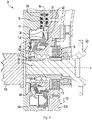
- clutch 24 includes a rotor 104 and a housing 102 (having a front part 102a and a rear part 102B) that generally surrounds the rotor 104 to define a working chamber 114 therebetween.
- the input component 32a is fixedly connected to the front part 102a of the housing 102 by one or more bolts (for example).
- An electromagnetically controlled valve assembly 106 regulates the flow of shear fluid (e.g., a conventional silicon oil shear fluid) from a fluid reservoir 112 through a return bore 138 to control clutch engagement.
- shear fluid e.g., a conventional silicon oil shear fluid
- An opening 126A is formed between front and rear sides of the rotor 104, and a channel 128 is formed in the rotor 104 between the opening 126A and an area adjacent to the return bore 138.
- the valve assembly 106 is configured to selectively permit shear fluid to pass out of the return bore 138, through the channel 128, and then to the working chamber 114. In this way, shear fluid can be delivered to the working chamber 114 at both the front and rear sides of the rotor 104 approximately simultaneously, and the working chamber can essentially fill from an outer diameter toward and inner diameter.
- the cover plate 140 of the valve assembly 106 is designed such that it is biased to uncover the opening 138 in the rear plate 112A of the reservoir 112 (i.e., an "on" or open position where the clutch 24 is engaged) by default, which permits shear fluid to flow from the reservoir 112 to the working chamber 114.
- This position of plate 140 is not shown.
- Shear fluid present in the working chamber 114 transmits torque by creating a frictional engagement between the rotor 104 and the housing 102, and the instantaneous percentage of torque transmission can vary as a function of the amount of shear fluid in the working chamber 114.
- the valve assembly 106 can be electromagnetically actuated to close the opening 138 (as shown in FIG. 4 ).
- the electromagnetic coil assembly 108 When the electromagnetic coil assembly 108 is energized (as controlled by controller 36), magnetic flux is generated by the coil 118 and is transmitted through the flux circuit to move the armature 144 toward the pole plate 178, which in turn moves the cover plate 140 toward the opening 138 in the rear plate 112A of the reservoir 112. In this way, energizing the coil assembly 108 causes the clutch 24 to disengage by covering the opening 138 more, which limits or prevents shear fluid from passing from the reservoir 112 to the working chamber 114 (as shown).
- cover plate 140 may be normally biased to cover the opening 138, and valve assembly 106 can be actuated to uncover the opening 138.
- the radial channel 128 is formed in the front side of the rotor 104, relative to the location of the cover plate 140 and the opening in the rear plate 112A of the reservoir 112.
- the radial channel 128 provides space for the cover plate 140 to move axially to cover and uncover the opening 138 in the rear plate 112A of the reservoir 112.
- the radial channel 128 and the groove 130 together form a fluid path between the opening 138 from the reservoir 112 to the opening 126A near the outer diameter (OD) of the rotor 104.
- fluid opening 126A one of the fluid openings (e.g., fluid opening 126A), which provides a fluid outlet that is substantially centered axially in the rotor and is substantially radially centered. Locating the fluid outlet at or near the axial center of the rotor 104 permits feeding shear fluid to the working chamber 114 at both the front and rear sides of the rotor substantially simultaneously, as well as permitting feeding the shear fluid to the working chamber 114 near the OD of the rotor 104.
- the fluid pump system that includes a fluid return path (not shown) pumps shear fluid from the working chamber 114 back to the reservoir 112.
- Shear fluid is essentially continuously pumped back from the working chamber 114 to the reservoir 112.
- the clutch 24 remains engaged only by continuing to keep the valve assembly 106 in an open position, allowing more shear fluid to move (i.e., return) from the reservoir 112 to the working chamber 114.
- the working chamber 114 can be effectively drained by moving the valve assembly 106 to a fully closed position, and preventing shear fluid from returning to the working chamber 114.
- the degree of energization of electromagnetic coil assembly 108 which affects the amount of shear fluid in the working chamber 114, which affects the degree of torque transmission between the input 32a and output 32b, is controlled by controller 36. That degree of energization may be controlled manually by an operator of the machine 10, or automatically by a program in the memory of controller 36.
- the degree of energization may be adjusted (metered) by closed loop control of the rotational speed of augers 20, 22 and 46, for which the relationship between auger speed and the volume transport rate is known, in order to provide a specific grain unload rate.
- the speed of the augers may be monitored for the closed loop control using a rotation sensor, or the unload rate may be monitored for the closed loop control using a flow measurement device, for example.
- the degree of energization may also be adjusted (metered) as a function of a sensed condition, such as a material clog or jam in augers 20, 22, 46 that is detected by a pressure sensor 59 ( FIG. 3 ) associated with output component 32b or one of the augers.
- a pressure sensor 59 FIG. 3
- the sensor 59 may sense a resistance to motion (i.e., rotation) of the output component 32b or auger. If a material clog is detected, then the pressure sensor 59 will communicate the same to the controller 36, and the controller 36 will disengage the clutch 24 to cease operation of the output component 32b.
- Controller 36 may also communicate with a fill sensor 70 located at or near the top of grain receptacle 16.
- a fill sensor 70 located at or near the top of grain receptacle 16.
- controller 36 slowly energizes coil assembly 38 via controller 36 to close the opening 138 in clutch 124, thereby slowing the introduction of grain into receptacle 16.
- controller 36 opens the opening 138 to a degree in which the input 32a and output 32b are coupled.
- clutch 24 is described for use with apparatus 18 for feeding or conveying the grain contained therein to unloader conveyor 12, it should be understood that clutch 24 can be employed in other areas of machine 10 requiring variable speed between input and output components by varying torque transmission.
- the controller 36 upon loading and executing software code or instructions which are tangibly stored on a tangible computer readable medium, such as on a magnetic medium, e.g., a computer hard drive, an optical medium, e.g., an optical disc, solid-state memory, e.g., flash memory, or other storage media known in the art.
- a tangible computer readable medium such as on a magnetic medium, e.g., a computer hard drive, an optical medium, e.g., an optical disc, solid-state memory, e.g., flash memory, or other storage media known in the art.
- any of the functionality performed by the controller 36 described herein such as the aforementioned method of operation, is implemented in software code or instructions which are tangibly stored on the tangible computer readable medium.
- the controller may perform any of the functionality of the controller described herein, including any steps of the aforementioned method described herein.
- software code or “code” used herein refers to any instructions or set of instructions that influence the operation of a computer or controller 36. They may exist in a computer-executable form, such as machine code, which is the set of instructions and data directly executed by a computer's central processing unit or by a controller, a human-understandable form, such as source code, which may be compiled in order to be executed by a computer's central processing unit or by a controller, or an intermediate form, such as object code, which is produced by a compiler.
- the term "software code” or “code” also includes any human-understandable computer instructions or set of instructions, e.g., a script, that may be executed on the fly with the aid of an interpreter executed by a computer's central processing unit or by a controller.
Landscapes
- Engineering & Computer Science (AREA)
- General Engineering & Computer Science (AREA)
- Mechanical Engineering (AREA)
- Physics & Mathematics (AREA)
- Life Sciences & Earth Sciences (AREA)
- Environmental Sciences (AREA)
- Electromagnetism (AREA)
- General Physics & Mathematics (AREA)
- Automation & Control Theory (AREA)
- Threshing Machine Elements (AREA)
Abstract
Description
- The present invention relates to an electronically controlled viscous coupler for a mechanical power transmission system, such as a grain unloading system of a combine harvester.
- As is described in
U.S. Patent No. 9,254,773 to CNH America LLC - It would be desirable to have a capability to control the unload rate of an unloader conveyor, for instance, to more accurately meter grain to top off trucks or other receptacles, and to fill smaller wagons and receptacles.
- In view of the foregoing Background, disclosed herein is a viscous clutch for use with combine grain tank unloading systems of combine harvesters. It should be understood, however, that the viscous clutch is not limited for use with unloading systems, rather, the viscous clutch is applicable for use with any variable speed (non-zero control) mechanical power transmission system, such as those systems in a combine harvester.
- According to one aspect of the invention, an apparatus for feeding or conveying grain comprises a conveyor for moving grain having an input end and an output end; and a viscous clutch either directly or indirectly connected to the input end of the conveyor for transmitting torque from an input component to the conveyor in a variable manner.
- According to another aspect of the invention, a method of feeding or conveying grain using a conveyor in an agricultural vehicle, said method comprising: operating a viscous clutch, which is either directly or indirectly connected to an input end of the conveyor, to transmit torque from an input component to the conveyor in a variable manner.
- The above-mentioned and other features and advantages of this invention, and the manner of attaining them, will become more apparent and the invention will be better understood by reference to the following description of an embodiment of the invention taken in conjunction with the accompanying drawings, wherein:
-
FIG. 1 is a simplified front view of a representative agricultural harvesting machine, including an unloader conveyor controllably operable for unloading grain from a grain tank of the machine into an accompanying receptacle, also shown. -
FIG. 2 is a simplified perspective view of aspects of the unloader conveyor ofFIG. 1 , in association with an apparatus controllable for feeding grain to the unloader conveyor. -
FIG. 3 is a simplified schematic representation of the unloader conveyor and associated apparatus ofFIGS. 1 and2 . -
FIG. 4 is a cross-sectional view of an exemplary viscous coupler for use with the apparatus ofFIG. 3 . - Corresponding reference characters indicate corresponding parts throughout the several views. The exemplification set out herein illustrates an embodiment of the invention, in one form, and such exemplification is not to be construed as limiting the scope of the invention in any manner.
- Inasmuch as various components and features of harvesters are of well-known design, construction, and operation to those skilled in the art, the details of such components and their operations will not generally be discussed in significant detail unless considered of pertinence to the present invention or desirable for purposes of better understanding.
- In the drawings, like numerals refer to like items, certain elements and features may be labeled or marked on a representative basis without each like element or feature necessarily being individually shown, labeled, or marked, and certain elements are labeled and marked in only some, but not all, of the drawing figures.
- Referring now the drawings, in
FIG. 1 , a representativeagricultural harvesting machine 10 is shown, including anunloader conveyor 12 operable for unloading grain from a grain holding device, which is aconventional grain tank 14, located on an upper region ofharvesting machine 10. Such amachine 10 is described in the '773 Patent. Here,harvesting machine 10 is depicted as a well-known, commercially available combine operable for harvesting a wide variety of grains, including, but not limited to, wheat, beans, corn, rice, and the like. Typically, the grain is harvested and threshed from stalks, pods, or other crop material, and conveyed away from a cleaning system ofmachine 10 by a clean grain conveyor to a grain elevator (not shown). The grain elevator then lifts the grain upwardly to a grain delivery conveyor which is operable for discharging the grain intograin tank 14. Whengrain tank 14 is filled with grain, or filled to a desired level,unloader conveyor 12 can be operated for unloading the grain fromtank 14, onto the ground, or into a wagon, truck or other vehicle, or a bin or other grain receptacle 16 (larger receptacle illustrated for example) or 16A (smaller receptacle). - Referring also to
FIGS. 2 and3 ,grain tank 14 includesapparatus 18 operable for feeding or conveying the grain contained therein tounloader conveyor 12. Here,apparatus 18 includes a pair ofconventional cross conveyors troughs 58 in a floor of the grain tank, in the well-known manner.Cross conveyors FIG. 2 , for conveying grain through therespective troughs 58 to anopening 26 in aninlet end 28 ofunloader conveyor 12. Each conveyor has aninput end 20a and anopposite output end 20b. Here also, it should be noted that althoughapparatus 18 ingrain tank 14 is illustrated including twocross conveyors unloader conveyor 12, a variety of other conveyor configurations can be utilized for performing this function, including, but not limited to, a single conveyor, or more than two conveyors, such as two cross conveyors that feed to a main conveyor, which, in turn, feeds the unloader conveyor. Also, although helical augers are shown,apparatus 18 can comprise other type conveyors, such as a moving belt or belts, or any other apparatus suitable for feeding grain to the unloader conveyor. -
Unloader conveyor 12 here includes an elongate upwardly or generally vertically extendingauger 46 supported for rotation in an upwardly extendingtubular housing 48, and anelongate auger 50 oriented horizontally or at a small acute angle to horizontal, supported for rotation in an elongatetubular housing 52 connected to and forming a continuation ofhousing 48.Housing 52 and an upper portion ofhousing 48 are supported in cantilever relation by a lower portion ofhousing 48 for rotation relative thereto, between a sidewardly extending unloading position as shown inFIG. 1 , and a rearwardly extending stowed position at about a 90 degree angle to the unloading position, in the well-known manner. Auger 50 is connected toauger 46 for rotation thereby in a suitable manner, such as by bevel gears, a Hooke's joint, or the like, also in the well-known manner. Auger 46 is driven by thedrive 30 connected thereto. - A
drive 30 is connected toconveyors machine 10, for example. Although only onedrive 30 is shown connected toconveyors machine 10 may include multipleindependent drives 30 for independently drivingconveyors - Drive 30 is connected to each of
conveyors input component 32a, aviscous clutch 24 and anoutput component 32b.Input component 32a andoutput component 32b may each be a shaft (such as a PTO shaft), a belt, or a chain, one or more gears, a gear box or a transmission that provides a two-stage reduction in power (for example) for driving theconveyors - A
separate clutch 24 is associated with eachconveyor FIG. 3 , the output of asingle clutch 24 may be connected to all of theconveyors output components 32b) by way of one or more belts, shafts, etc. for simultaneously controlling all of thoseconveyors clutch 24 accomplishes variable speed control for eachconveyor input component 32a. Eachclutch 24 is shown connected to the output side of theinput component 32a and the input side of theoutput component 32b. The output side of theoutput component 32b is either directly or indirectly connected to one of theconveyors FIG. 3 , eachclutch 24 may be connected directly betweendrive 30 and one of theconveyors -
Machine 10 further comprises acontrol 34 that is operable for controllingunloader conveyor 12 andapparatus 18. Elements ofcontrol 34 include a processor basedcontroller 36 that is connected to aninput device 38, drive 30 andclutches 24 by suitableconductive paths 44.Paths 44 can be, for instance, wires of a wiring harness, or a wired or wireless communications network. To facilitate convenient and simple operation,input device 38 can be located on a multi-function or propulsion handle 60 (FIG. 3 ) or other location on themachine 10. - Turning now to
FIG. 4 , eachclutch 24 is an electromagnetically actuated viscous clutch. The details of such an exemplary clutch for use withmachine 10 are described inU.S. Patent No. 8,100,241 , which is incorporated by reference herein in its entirety and for all purposes. Theclutch 24 permits selective engagement betweeninput component 32a (connected to drive 30) andoutput component 32b (connected to one of theconveyors conveyors input component 32a. In a closed position of the clutch, rotation of theinput component 32a is transmitted to theoutput component 32b, whereas, in an open position of the clutch, rotation of theinput component 32a is not transmitted to theoutput component 32b. It is noted that clutch may not, necessarily, achieve full decoupling.Controller 36 is connected toclutches 24 for selectively varying (i.e., metering) the torque transmission between theinput component 32a and theoutput component 32b. - Referring now to the details of the
clutch 24,clutch 24 includes arotor 104 and a housing 102 (having a front part 102a and arear part 102B) that generally surrounds therotor 104 to define a workingchamber 114 therebetween. Theinput component 32a, is fixedly connected to the front part 102a of thehousing 102 by one or more bolts (for example). An electromagnetically controlledvalve assembly 106 regulates the flow of shear fluid (e.g., a conventional silicon oil shear fluid) from afluid reservoir 112 through areturn bore 138 to control clutch engagement. An opening 126A is formed between front and rear sides of therotor 104, and achannel 128 is formed in therotor 104 between the opening 126A and an area adjacent to thereturn bore 138. Thevalve assembly 106 is configured to selectively permit shear fluid to pass out of thereturn bore 138, through thechannel 128, and then to theworking chamber 114. In this way, shear fluid can be delivered to theworking chamber 114 at both the front and rear sides of therotor 104 approximately simultaneously, and the working chamber can essentially fill from an outer diameter toward and inner diameter. - The
cover plate 140 of thevalve assembly 106 is designed such that it is biased to uncover the opening 138 in therear plate 112A of the reservoir 112 (i.e., an "on" or open position where theclutch 24 is engaged) by default, which permits shear fluid to flow from thereservoir 112 to theworking chamber 114. This position ofplate 140 is not shown. Shear fluid present in the workingchamber 114 transmits torque by creating a frictional engagement between therotor 104 and thehousing 102, and the instantaneous percentage of torque transmission can vary as a function of the amount of shear fluid in the workingchamber 114. - The
valve assembly 106 can be electromagnetically actuated to close the opening 138 (as shown inFIG. 4 ). When theelectromagnetic coil assembly 108 is energized (as controlled by controller 36), magnetic flux is generated by thecoil 118 and is transmitted through the flux circuit to move thearmature 144 toward thepole plate 178, which in turn moves thecover plate 140 toward theopening 138 in therear plate 112A of thereservoir 112. In this way, energizing thecoil assembly 108 causes the clutch 24 to disengage by covering theopening 138 more, which limits or prevents shear fluid from passing from thereservoir 112 to the working chamber 114 (as shown). - As an alternative to the arrangement described above,
cover plate 140 may be normally biased to cover theopening 138, andvalve assembly 106 can be actuated to uncover theopening 138. - The
radial channel 128 is formed in the front side of therotor 104, relative to the location of thecover plate 140 and the opening in therear plate 112A of thereservoir 112. Theradial channel 128 provides space for thecover plate 140 to move axially to cover and uncover theopening 138 in therear plate 112A of thereservoir 112. In addition, theradial channel 128 and thegroove 130 together form a fluid path between the opening 138 from thereservoir 112 to theopening 126A near the outer diameter (OD) of therotor 104. In that way, input of shear fluid to the workingchamber 114 occurs at one of the fluid openings (e.g.,fluid opening 126A), which provides a fluid outlet that is substantially centered axially in the rotor and is substantially radially centered. Locating the fluid outlet at or near the axial center of therotor 104 permits feeding shear fluid to the workingchamber 114 at both the front and rear sides of the rotor substantially simultaneously, as well as permitting feeding the shear fluid to the workingchamber 114 near the OD of therotor 104. - During operation, the fluid pump system that includes a fluid return path (not shown) pumps shear fluid from the working
chamber 114 back to thereservoir 112. Shear fluid is essentially continuously pumped back from the workingchamber 114 to thereservoir 112. The clutch 24 remains engaged only by continuing to keep thevalve assembly 106 in an open position, allowing more shear fluid to move (i.e., return) from thereservoir 112 to the workingchamber 114. Conversely, the workingchamber 114 can be effectively drained by moving thevalve assembly 106 to a fully closed position, and preventing shear fluid from returning to the workingchamber 114. - The degree of energization of
electromagnetic coil assembly 108, which affects the amount of shear fluid in the workingchamber 114, which affects the degree of torque transmission between theinput 32a andoutput 32b, is controlled bycontroller 36. That degree of energization may be controlled manually by an operator of themachine 10, or automatically by a program in the memory ofcontroller 36. The degree of energization may be adjusted (metered) by closed loop control of the rotational speed ofaugers augers FIG. 3 ) associated withoutput component 32b or one of the augers. Alternatively, thesensor 59 may sense a resistance to motion (i.e., rotation) of theoutput component 32b or auger. If a material clog is detected, then thepressure sensor 59 will communicate the same to thecontroller 36, and thecontroller 36 will disengage the clutch 24 to cease operation of theoutput component 32b. -
Controller 36 may also communicate with a fill sensor 70 located at or near the top ofgrain receptacle 16. In operation, as the grain fills thereceptacle 16 and eventually reaches the fill sensor 70, the fill sensor 70 transmits a signal tocontroller 36 such that thecontroller 36 understands the fill status ofreceptacle 16. In response thereto,controller 36 slowly energizescoil assembly 38 viacontroller 36 to close theopening 138 in clutch 124, thereby slowing the introduction of grain intoreceptacle 16. Eventually,controller 36 opens theopening 138 to a degree in which theinput 32a andoutput 32b are coupled. - Although clutch 24 is described for use with
apparatus 18 for feeding or conveying the grain contained therein to unloaderconveyor 12, it should be understood that clutch 24 can be employed in other areas ofmachine 10 requiring variable speed between input and output components by varying torque transmission. - It is to be understood that the above-described operating steps are performed by the
controller 36 upon loading and executing software code or instructions which are tangibly stored on a tangible computer readable medium, such as on a magnetic medium, e.g., a computer hard drive, an optical medium, e.g., an optical disc, solid-state memory, e.g., flash memory, or other storage media known in the art. Thus, any of the functionality performed by thecontroller 36 described herein, such as the aforementioned method of operation, is implemented in software code or instructions which are tangibly stored on the tangible computer readable medium. Upon loading and executing such software code or instructions by the controller, the controller may perform any of the functionality of the controller described herein, including any steps of the aforementioned method described herein. - The term "software code" or "code" used herein refers to any instructions or set of instructions that influence the operation of a computer or
controller 36. They may exist in a computer-executable form, such as machine code, which is the set of instructions and data directly executed by a computer's central processing unit or by a controller, a human-understandable form, such as source code, which may be compiled in order to be executed by a computer's central processing unit or by a controller, or an intermediate form, such as object code, which is produced by a compiler. As used herein, the term "software code" or "code" also includes any human-understandable computer instructions or set of instructions, e.g., a script, that may be executed on the fly with the aid of an interpreter executed by a computer's central processing unit or by a controller. - While this invention has been described with respect to at least one embodiment, the present invention can be further modified within the spirit and scope of this disclosure. This application is therefore intended to cover any variations, uses, or adaptations of the invention using its general principles. Further, this application is intended to cover such departures from the present disclosure as come within known or customary practice in the art to which this invention pertains and which fall within the limits of the appended claims.
Claims (16)
- An apparatus [18] for feeding or conveying grain including a conveyor [20/22] for moving grain and having an input end and an output end, characterized in that the apparatus [18] further comprises a viscous clutch [24] either directly or indirectly connected to the input end of the conveyor [20/22] for transmitting torque from an input component [32a] to the input end of the conveyor [20/22].
- The apparatus [18] of claim 1, characterized in that the viscous clutch [24] comprises a rotor [104], a housing [102] that generally surrounds the rotor [104] to define a working chamber [114] therebetween, and an electromagnetic coil assembly [106] for controlling a flow of fluid into the working chamber [114], wherein the rotor [104] is either directly or indirectly connected to one of the conveyor [20/22] and the input component [32a], and the housing [102] is either directly or indirectly connected to the other of the conveyor [20/22] and the input component [32a].
- The apparatus [18] of claim 2, characterized in that the input component [32a] is an engine, a shaft, a chain or a belt.
- The apparatus [18] of claim 1, characterized in that the apparatus [18] further comprises a controller [36] that is configured to either energize or deenergize the clutch [24] to adjust a torque imparted to the conveyor [20/22] by the input component [32a].
- The apparatus [18] of claim 4, characterized in that the apparatus [18] further comprises a sensor [59] connected to the controller [36] for detecting motion of the conveyor [20/22], and wherein the controller [36] is configured to adjust a torque transmitted by the viscous clutch [24] as a function of the detected motion.
- The apparatus [18] of claim 4, characterized in that the apparatus [18] further comprises a sensor [70] connected to the controller [36] for detecting a fill level of a receptacle [16] that receives the conveyed grain from the apparatus, [18] and wherein the controller [36] is configured to adjust a torque and speed transmitted by the viscous clutch [24] as a function of the detected fill level.
- The apparatus [18] of claim 1, characterized in that the apparatus [18] further comprises an unloader conveyor [12] having an input end adjacent the output end of the conveyor [20/22].
- The apparatus [18] of claim 1, characterized in that the conveyor [20/22] is an auger.
- The apparatus [18] of claim 1, characterized in that the apparatus [18] further comprises a second conveyor [22] and a second viscous clutch [24] that is connected to the second conveyor [22], wherein each of the conveyors [20/22] is a cross-auger.
- An agricultural vehicle [10], in particular a combine harvester [10], comprising the apparatus [18] of claim 1.
- A method of feeding or conveying grain using a conveyor [20/22] in an agricultural vehicle [10], characterized in that said method comprises:
operating a viscous clutch [24], which is either directly or indirectly connected to an input end of the conveyor [20/22], to transmit torque from an input component [32a] to the conveyor [20/22] in a variable manner. - The method of claim 11, characterized in that the operating step comprises either energizing or deenergizing the viscous clutch [24].
- The method of claim 12, characterized in that the method further comprises metering energization of the viscous clutch [24] to adjust a level of torque transmission between the input component [32a] and the conveyor [20/22].
- The method of claim 13, characterized in that the energizing step is performed by a controller [36] of the agricultural vehicle [10].
- The method of claim 11, characterized in that the method further comprises detecting motion of the conveyor [20/22] and metering energization of the viscous clutch [24] as a function of the detected motion.
- The method of claim 11, characterized in that the method further comprises detecting a fill level of a receptacle [16] that receives the conveyed grain, and operating the viscous clutch [24] based upon the detected fill level.
Applications Claiming Priority (1)
| Application Number | Priority Date | Filing Date | Title |
|---|---|---|---|
| US17/245,260 US12150412B2 (en) | 2021-04-30 | 2021-04-30 | Electronically controlled viscous coupler for combine harvester |
Publications (2)
| Publication Number | Publication Date |
|---|---|
| EP4082946A1 true EP4082946A1 (en) | 2022-11-02 |
| EP4082946B1 EP4082946B1 (en) | 2024-12-11 |
Family
ID=81346159
Family Applications (1)
| Application Number | Title | Priority Date | Filing Date |
|---|---|---|---|
| EP22169224.7A Active EP4082946B1 (en) | 2021-04-30 | 2022-04-21 | Agricultural vehicle with electronically controlled viscous coupler |
Country Status (2)
| Country | Link |
|---|---|
| US (1) | US12150412B2 (en) |
| EP (1) | EP4082946B1 (en) |
Families Citing this family (4)
| Publication number | Priority date | Publication date | Assignee | Title |
|---|---|---|---|---|
| US12150412B2 (en) * | 2021-04-30 | 2024-11-26 | Cnh Industrial America Llc | Electronically controlled viscous coupler for combine harvester |
| US12582033B2 (en) | 2023-04-13 | 2026-03-24 | Deere & Company | Systems and methods for automated grain cart unloading |
| US12472911B2 (en) | 2023-07-11 | 2025-11-18 | Deere & Company | Systems and methods for ground distance control |
| US12588589B2 (en) | 2023-10-02 | 2026-03-31 | Deere & Company | Systems and methods for controlling harvested material fill profiles |
Citations (5)
| Publication number | Priority date | Publication date | Assignee | Title |
|---|---|---|---|---|
| CN1095038A (en) * | 1994-01-21 | 1994-11-16 | 北京航空航天大学 | The driving device that is used for transport plane |
| US20090084650A1 (en) * | 2005-07-29 | 2009-04-02 | Horton, Inc. | Electromagnetically Actuated Viscous Clutch |
| US20130089398A1 (en) * | 2011-10-11 | 2013-04-11 | Herbert M. Farley | Grain unloading control system |
| CN103939497A (en) * | 2014-03-11 | 2014-07-23 | 山东科技大学 | Transmission device with stepless speed regulating function |
| US9254773B2 (en) | 2008-05-22 | 2016-02-09 | Cnh Industrial America Llc | Adaptive rate control for feeding grain to a grain unloader conveyor |
Family Cites Families (97)
| Publication number | Priority date | Publication date | Assignee | Title |
|---|---|---|---|---|
| US1663825A (en) * | 1927-01-03 | 1928-03-27 | William C Benjamin | Grain loader |
| US2617351A (en) * | 1945-02-17 | 1952-11-11 | American Dairies Inc | Apparatus for charging and storing materials |
| US2756887A (en) * | 1952-12-17 | 1956-07-31 | Int Harvester Co | Self-unloading vehicle |
| US2771203A (en) * | 1955-02-24 | 1956-11-20 | Int Harvester Co | Vehicle with self-unloading mechanism |
| US3214049A (en) * | 1962-07-12 | 1965-10-26 | Grove Mfg Company | Self-unloading forage vehicle |
| US3286862A (en) * | 1964-08-05 | 1966-11-22 | Elmer K Hansen | Self-unloading feed wagon |
| US3380320A (en) * | 1965-12-06 | 1968-04-30 | Ambrose E. Zierick | Hydraulic super-charged variable transmission |
| US3345042A (en) * | 1966-02-18 | 1967-10-03 | Blair Mfg Co | Cattle feeding device |
| US3460698A (en) * | 1968-03-04 | 1969-08-12 | Harris & Thrush Mfg Co | Farm cart |
| US3511399A (en) * | 1968-05-14 | 1970-05-12 | Int Harvester Co | Forage feeder |
| US3612410A (en) * | 1969-06-02 | 1971-10-12 | Charles W Steinke | Combination six-wheel-drive vehicle and self-unloading box |
| US3760770A (en) * | 1972-05-31 | 1973-09-25 | Weaverline Corp | Battery powered feed cart |
| US3825138A (en) * | 1972-10-24 | 1974-07-23 | Mathews B | Unloader for the grain bin of a combine |
| GB1548381A (en) * | 1975-06-26 | 1979-07-11 | Clayson Nv | Harvesting machines |
| US3873032A (en) * | 1973-11-12 | 1975-03-25 | Jr James C Jellis | Material feeding apparatus |
| US3999674A (en) * | 1975-09-02 | 1976-12-28 | International Harvester Company | Bale loader and shredder |
| US4033518A (en) * | 1976-05-24 | 1977-07-05 | Gehl Company | Forage harvester |
| DE2632060C3 (en) * | 1976-07-16 | 1981-07-16 | Maschinenfabrik Fahr Ag Gottmadingen, 7702 Gottmadingen | Unloading device on an agricultural vehicle, in particular a loading wagon |
| US4466759A (en) * | 1982-02-22 | 1984-08-21 | Conoco Inc. | Method and apparatus for sequence control of vertical movements of slurried particulates |
| US4484861A (en) * | 1982-02-22 | 1984-11-27 | Conoco Inc. | Method and apparatus for process control of vertical movement of slurried particulates |
| US4898267A (en) * | 1989-04-27 | 1990-02-06 | Eaton Corporation | Electroviscous fluid clutch |
| US5100281A (en) * | 1989-07-26 | 1992-03-31 | J. & M. Manufacturing Co., Inc. | Grain wagon with unload mechanism |
| NL9500561A (en) * | 1995-03-23 | 1996-11-01 | Campen Beheer B V Van | Metering device for feed |
| FR2752566B1 (en) * | 1996-07-26 | 1998-12-04 | Desvoys Et Fils | DEVICE FOR CONVEYING GRANULAR OR FIBROUS BULK PRODUCTS, IN PARTICULAR FOR SIDE UNLOADING OF SUCH PRODUCTS IN DISPENSING BINS |
| DE19750976A1 (en) * | 1997-11-18 | 1999-06-02 | Mannesmann Sachs Ag | Air conditioning compressor drive with viscous-fluid clutch |
| JP2000199531A (en) * | 1999-01-06 | 2000-07-18 | Usui Internatl Ind Co Ltd | Liquid clutch |
| JP2001224233A (en) * | 2000-02-16 | 2001-08-21 | Yanmar Agricult Equip Co Ltd | Combine discharge auger |
| US6430904B1 (en) * | 2001-05-09 | 2002-08-13 | Deere & Company | Platform auger torque sensing brake activation |
| US6651412B1 (en) * | 2002-10-29 | 2003-11-25 | New Holland North America, Inc. | Forward clutch drive for windrow header with positive reverse drive |
| US6984172B2 (en) * | 2004-01-14 | 2006-01-10 | Cnh America Llc | Dual power path drive for a rotating threshing rotor of an agricultural combine and method for decelerating the rotor |
| US7540700B2 (en) * | 2004-06-17 | 2009-06-02 | Deere & Company | Grain cart with intermodal container loader |
| US7980373B2 (en) * | 2004-08-30 | 2011-07-19 | Borgwarner Inc. | Electronically controlled fluid coupling device with fluid scavenge control |
| EP1674752B1 (en) * | 2004-12-23 | 2008-10-01 | Borgwarner, Inc. | Viscous fluid clutch |
| US8930089B2 (en) * | 2006-05-25 | 2015-01-06 | Barry H. Reeves | System and method for indicating to a remote location operation of an auger or the like |
| US8221047B2 (en) * | 2007-02-15 | 2012-07-17 | Unverferth Manufacturing Company, Inc. | Seed carrier with pivoting conveyor |
| US8434624B2 (en) * | 2007-10-15 | 2013-05-07 | Redekop Enterprises Inc | Harvesting corn cobs |
| US8056695B2 (en) * | 2008-07-10 | 2011-11-15 | Deere & Company | Adaptive soft start system for mower blade clutch engagement |
| JP5382908B2 (en) * | 2008-10-02 | 2014-01-08 | ヤンマー株式会社 | Combine |
| US20120099948A1 (en) * | 2010-10-21 | 2012-04-26 | Digi-Star, LLC, a Wisconsin Limited Liability Company | Automatic start / stop controls for agricultural load and transfer equipment |
| US20100209223A1 (en) * | 2009-02-13 | 2010-08-19 | Unverferth Manufacturing Company, Inc. | Grain cart with folding auger |
| WO2010122055A1 (en) * | 2009-04-22 | 2010-10-28 | Technische Universität Dresden | Self-propelled harvester having an electrically driven threshing drum |
| AT12114U1 (en) * | 2009-11-03 | 2011-11-15 | Steimle Heinz | UNLOADING MODULE AND AGRICULTURAL TRAILER |
| BR112012011837A2 (en) * | 2009-11-17 | 2018-09-11 | Horton Inc | integrated viscous clutch |
| KR101799073B1 (en) * | 2010-08-19 | 2017-11-17 | 호르톤 인코포레이티드 | Viscous clutch valve assembly |
| JP5681577B2 (en) * | 2011-06-30 | 2015-03-11 | 株式会社クボタ | Combine |
| US10426092B2 (en) * | 2011-07-25 | 2019-10-01 | Unverferth Manufacturing Company, Inc. | Dual auger grain cart with adjustable forward reach |
| US9706713B2 (en) * | 2011-07-25 | 2017-07-18 | Unverferth Manufacturing Company, Inc. | Grain cart with folding auger having adjustable elevation |
| CA2772342C (en) * | 2012-02-22 | 2016-05-24 | Flaman Sales Ltd. | Adjustable hopper for use with a portable grain auger |
| US9113598B2 (en) * | 2012-03-20 | 2015-08-25 | J. & M. Manufacturing Co., Inc. | Grain cart having an inclined folding unloading auger conveyor with an askewed flow control spout |
| CN104508273B (en) * | 2012-06-27 | 2017-10-24 | 博格华纳公司 | The viscous fan drive system for feedback of being skidded with fans drive |
| US9624988B2 (en) * | 2012-09-22 | 2017-04-18 | Horton, Inc. | Viscous clutch with return bore through rotor |
| DE102013101553A1 (en) * | 2013-02-15 | 2014-06-26 | Kendrion Linnig Gmbh | Armature assembly for electromagnetic clutch for transmitting torque from drive shaft on accessory in motor car, has fixing gripping unit comprising integral part of armature disk and portion of reset plate spring in integral part of spring |
| DE102013101556A1 (en) * | 2013-02-15 | 2014-04-10 | Kendrion Linnig Gmbh | Fluid friction clutch for transferring drive torque from primary-side drive shaft onto secondary-side accessories, has bimetal mechanism with bimetal portion, which is assigned to control valve |
| AU2014240621B2 (en) * | 2013-03-14 | 2017-06-29 | Horton, Inc. | Viscous clutch and associated reservoir configuration |
| JP6200060B2 (en) * | 2013-03-14 | 2017-09-20 | ホートン, インコーポレイテッド | Viscous clutch with minimum output speed |
| US20140365170A1 (en) * | 2013-03-15 | 2014-12-11 | Unverferth Manufacturing Company, Inc. | Grain cart with intergrated moisture sensor |
| US9272853B2 (en) * | 2013-03-15 | 2016-03-01 | Unverferth Manufacturing Company, Inc. | Weight-based chute control for a farm implement |
| CN103224117B (en) * | 2013-05-10 | 2016-02-03 | 深圳市华星光电技术有限公司 | A kind of automatic feedback regulates cullet to transmit the system of tension force |
| KR101902671B1 (en) * | 2014-04-04 | 2018-09-28 | 얀마 가부시키가이샤 | Combine |
| US20150353283A1 (en) * | 2014-06-04 | 2015-12-10 | Goodrich Corporation | Torque control cargo loading systems and methods |
| DE102014108025A1 (en) * | 2014-06-06 | 2015-12-17 | Claas Selbstfahrende Erntemaschinen Gmbh | Harvester |
| DE102014213445A1 (en) * | 2014-07-10 | 2016-01-14 | Deere & Company | Inclined conveyor assembly for a combine harvester |
| KR102406944B1 (en) * | 2014-09-11 | 2022-06-10 | 가부시끼 가이샤 구보다 | Combine |
| KR102446617B1 (en) * | 2014-09-25 | 2022-09-23 | 가부시끼 가이샤 구보다 | harvest |
| KR102521831B1 (en) * | 2015-03-18 | 2023-04-17 | 가부시끼 가이샤 구보다 | Combine harvester |
| WO2017038641A1 (en) * | 2015-09-01 | 2017-03-09 | ヤンマー株式会社 | Combine |
| US20170089409A1 (en) * | 2015-09-29 | 2017-03-30 | Ford Global Technologies, Llc | Liquid Cooled Fan Clutch |
| US9826683B2 (en) * | 2015-11-04 | 2017-11-28 | Deere & Company | Grain mass flow rate determination |
| WO2017075676A1 (en) * | 2015-11-05 | 2017-05-11 | Alfredo Antonio Palou | Machine for extracting products stored in silo bags with automatic advance and guidance |
| CN115299238B (en) * | 2015-12-22 | 2024-07-02 | 株式会社久保田 | Harvester |
| CN208724407U (en) * | 2015-12-22 | 2019-04-12 | 株式会社久保田 | Harvester |
| WO2017155062A1 (en) * | 2016-03-10 | 2017-09-14 | ヤンマー株式会社 | Combine harvester |
| EP3516253B1 (en) * | 2016-09-23 | 2021-11-17 | Horton, Inc. | Modular viscous clutch |
| US10159191B2 (en) * | 2016-09-23 | 2018-12-25 | Deere & Company | Harvester grain unloader |
| US10023389B1 (en) * | 2017-04-24 | 2018-07-17 | Cnh Industrial America Llc | Extendable unload conveyor for combine |
| JP7116533B2 (en) * | 2017-06-16 | 2022-08-10 | ヤンマーパワーテクノロジー株式会社 | combine |
| JP6839286B2 (en) * | 2017-08-03 | 2021-03-03 | アルプスアルパイン株式会社 | Operating device |
| US10820503B2 (en) * | 2017-09-15 | 2020-11-03 | Deere & Company | Monitoring device for monitoring crop yield |
| US10736271B2 (en) * | 2017-11-01 | 2020-08-11 | Deere & Company | Automatic product fill method and control system |
| US11369060B2 (en) * | 2018-02-19 | 2022-06-28 | Cnh Industrial America Llc | Removable auger trough |
| US10448575B1 (en) * | 2018-04-10 | 2019-10-22 | Unverferth Manufacturing Company, Inc. | Auger flight extension for a farm implement |
| US11771009B2 (en) * | 2018-04-30 | 2023-10-03 | Casey Heim | Method and system for conveying material in a combine harvester |
| US10518980B2 (en) * | 2018-05-04 | 2019-12-31 | Unverferth Manufacturing Company, Inc. | Auger coupling assembly with a pivotable clutch |
| US10806084B2 (en) * | 2018-05-07 | 2020-10-20 | Cnh Industrial America Llc | System for unloading harvested crop from an agricultural harvester |
| US10806085B2 (en) * | 2018-05-07 | 2020-10-20 | Cnh Industrial America Llc | System for unloading harvested crop from an agricultural harvester |
| JP7045308B2 (en) * | 2018-12-19 | 2022-03-31 | ヤンマーパワーテクノロジー株式会社 | Discharge part diagnostic system |
| US10624269B1 (en) * | 2019-03-01 | 2020-04-21 | Cnh Industrial America Llc | Unloading system for agricultural combine |
| US10743474B1 (en) * | 2019-03-20 | 2020-08-18 | Unverferth Manufacturing Co., Inc. | Dual auger drive system |
| DE102019002637A1 (en) * | 2019-04-10 | 2020-10-15 | Claas Selbstfahrende Erntemaschinen Gmbh | Harvesting machine and screw conveyor for it |
| WO2020219951A1 (en) * | 2019-04-25 | 2020-10-29 | Bergkamp Incorporated | Telescoping rotatable tool |
| US20200354154A1 (en) * | 2019-05-07 | 2020-11-12 | J. & M. Manufacturing Co., Inc. | Agricultural device for transferring seed or grain |
| US11445664B2 (en) * | 2019-05-10 | 2022-09-20 | Deere & Company | Auger assembly for harvesting machine |
| US11019771B2 (en) * | 2019-05-15 | 2021-06-01 | Unverferth Manufacturing Company, Inc. | Convertible dual-sided auger system for a farm implement |
| US10542677B1 (en) * | 2019-05-29 | 2020-01-28 | Safe-T-Pull, Inc. | Crop cart cleaning and unloading system |
| CN110476589B (en) * | 2019-08-22 | 2024-09-06 | 星光农机股份有限公司 | Harvesting and bundling integrated machine |
| CA3072823C (en) * | 2020-02-18 | 2020-09-22 | Ryan J. Dennis | Fan-equipped dual-purpose grain cart for transporting and drying grain |
| US12150412B2 (en) * | 2021-04-30 | 2024-11-26 | Cnh Industrial America Llc | Electronically controlled viscous coupler for combine harvester |
-
2021
- 2021-04-30 US US17/245,260 patent/US12150412B2/en active Active
-
2022
- 2022-04-21 EP EP22169224.7A patent/EP4082946B1/en active Active
Patent Citations (6)
| Publication number | Priority date | Publication date | Assignee | Title |
|---|---|---|---|---|
| CN1095038A (en) * | 1994-01-21 | 1994-11-16 | 北京航空航天大学 | The driving device that is used for transport plane |
| US20090084650A1 (en) * | 2005-07-29 | 2009-04-02 | Horton, Inc. | Electromagnetically Actuated Viscous Clutch |
| US8100241B2 (en) | 2005-07-29 | 2012-01-24 | Horton, Inc. | Viscous clutch with eddy current reduction |
| US9254773B2 (en) | 2008-05-22 | 2016-02-09 | Cnh Industrial America Llc | Adaptive rate control for feeding grain to a grain unloader conveyor |
| US20130089398A1 (en) * | 2011-10-11 | 2013-04-11 | Herbert M. Farley | Grain unloading control system |
| CN103939497A (en) * | 2014-03-11 | 2014-07-23 | 山东科技大学 | Transmission device with stepless speed regulating function |
Also Published As
| Publication number | Publication date |
|---|---|
| EP4082946B1 (en) | 2024-12-11 |
| US20220348412A1 (en) | 2022-11-03 |
| US12150412B2 (en) | 2024-11-26 |
Similar Documents
| Publication | Publication Date | Title |
|---|---|---|
| EP4082946B1 (en) | Agricultural vehicle with electronically controlled viscous coupler | |
| US9254773B2 (en) | Adaptive rate control for feeding grain to a grain unloader conveyor | |
| EP2934084B1 (en) | Method of controlling a conveyance rate of grain of an unloader system | |
| EP3146831B1 (en) | Agricultural vehicle control system | |
| EP2382854B1 (en) | An agricultural combine with draper header | |
| US9156624B2 (en) | Grain unloading control system | |
| US8869522B2 (en) | Drive system for an infeed conveyor of a harvester | |
| EP4048055B1 (en) | Controlled lateral belt reverse for draper head of agricultural combine | |
| US6475081B2 (en) | Throughput control for combines having a variable torque sensing drive | |
| US20070183878A1 (en) | Grain tank unloader and clean out control | |
| EP2514296A1 (en) | Grain unloading system | |
| US10791673B2 (en) | Drive system having hydraulic power transmission for a harvesting header of a harvester | |
| AU3818602A (en) | Platform auger torque sensing brake activation | |
| EP3811761B1 (en) | Reversible compression auger on harvesting header | |
| EP0678236A1 (en) | Grain tank unloading auger drive means | |
| CA2443299C (en) | Harvesting machine | |
| US9848537B2 (en) | Drive system for combine harvester processor | |
| AU2614102A (en) | Crop moisture sensor for controlling harvesting speed | |
| EP4548747A1 (en) | A hydraulic drive system for the cleaning fan of a combine harvester | |
| EP3672390B1 (en) | Drive system for an agricultural unloader | |
| EP4656031A1 (en) | A forage harvester | |
| US20240276917A1 (en) | Forage Harvesters | |
| EP4578261A1 (en) | System and method for detecting rotor slugging of an agricultural harvester | |
| CN112385389A (en) | Harvester with reversing function |
Legal Events
| Date | Code | Title | Description |
|---|---|---|---|
| PUAI | Public reference made under article 153(3) epc to a published international application that has entered the european phase |
Free format text: ORIGINAL CODE: 0009012 |
|
| STAA | Information on the status of an ep patent application or granted ep patent |
Free format text: STATUS: THE APPLICATION HAS BEEN PUBLISHED |
|
| AK | Designated contracting states |
Kind code of ref document: A1 Designated state(s): AL AT BE BG CH CY CZ DE DK EE ES FI FR GB GR HR HU IE IS IT LI LT LU LV MC MK MT NL NO PL PT RO RS SE SI SK SM TR |
|
| STAA | Information on the status of an ep patent application or granted ep patent |
Free format text: STATUS: REQUEST FOR EXAMINATION WAS MADE |
|
| 17P | Request for examination filed |
Effective date: 20230502 |
|
| RBV | Designated contracting states (corrected) |
Designated state(s): AL AT BE BG CH CY CZ DE DK EE ES FI FR GB GR HR HU IE IS IT LI LT LU LV MC MK MT NL NO PL PT RO RS SE SI SK SM TR |
|
| P01 | Opt-out of the competence of the unified patent court (upc) registered |
Effective date: 20240320 |
|
| GRAP | Despatch of communication of intention to grant a patent |
Free format text: ORIGINAL CODE: EPIDOSNIGR1 |
|
| STAA | Information on the status of an ep patent application or granted ep patent |
Free format text: STATUS: GRANT OF PATENT IS INTENDED |
|
| RIC1 | Information provided on ipc code assigned before grant |
Ipc: A01D 41/12 20060101ALI20240619BHEP Ipc: F16D 35/00 20060101ALI20240619BHEP Ipc: B65G 33/34 20060101ALI20240619BHEP Ipc: B65G 33/08 20060101AFI20240619BHEP |
|
| INTG | Intention to grant announced |
Effective date: 20240705 |
|
| GRAS | Grant fee paid |
Free format text: ORIGINAL CODE: EPIDOSNIGR3 |
|
| GRAA | (expected) grant |
Free format text: ORIGINAL CODE: 0009210 |
|
| STAA | Information on the status of an ep patent application or granted ep patent |
Free format text: STATUS: THE PATENT HAS BEEN GRANTED |
|
| AK | Designated contracting states |
Kind code of ref document: B1 Designated state(s): AL AT BE BG CH CY CZ DE DK EE ES FI FR GB GR HR HU IE IS IT LI LT LU LV MC MK MT NL NO PL PT RO RS SE SI SK SM TR |
|
| REG | Reference to a national code |
Ref country code: GB Ref legal event code: FG4D |
|
| REG | Reference to a national code |
Ref country code: CH Ref legal event code: EP |
|
| REG | Reference to a national code |
Ref country code: IE Ref legal event code: FG4D |
|
| REG | Reference to a national code |
Ref country code: DE Ref legal event code: R096 Ref document number: 602022008533 Country of ref document: DE |
|
| REG | Reference to a national code |
Ref country code: LT Ref legal event code: MG9D |
|
| PG25 | Lapsed in a contracting state [announced via postgrant information from national office to epo] |
Ref country code: HR Free format text: LAPSE BECAUSE OF FAILURE TO SUBMIT A TRANSLATION OF THE DESCRIPTION OR TO PAY THE FEE WITHIN THE PRESCRIBED TIME-LIMIT Effective date: 20241211 |
|
| PG25 | Lapsed in a contracting state [announced via postgrant information from national office to epo] |
Ref country code: FI Free format text: LAPSE BECAUSE OF FAILURE TO SUBMIT A TRANSLATION OF THE DESCRIPTION OR TO PAY THE FEE WITHIN THE PRESCRIBED TIME-LIMIT Effective date: 20241211 |
|
| PG25 | Lapsed in a contracting state [announced via postgrant information from national office to epo] |
Ref country code: BG Free format text: LAPSE BECAUSE OF FAILURE TO SUBMIT A TRANSLATION OF THE DESCRIPTION OR TO PAY THE FEE WITHIN THE PRESCRIBED TIME-LIMIT Effective date: 20241211 |
|
| REG | Reference to a national code |
Ref country code: NL Ref legal event code: MP Effective date: 20241211 |
|
| PG25 | Lapsed in a contracting state [announced via postgrant information from national office to epo] |
Ref country code: ES Free format text: LAPSE BECAUSE OF FAILURE TO SUBMIT A TRANSLATION OF THE DESCRIPTION OR TO PAY THE FEE WITHIN THE PRESCRIBED TIME-LIMIT Effective date: 20241211 |
|
| PG25 | Lapsed in a contracting state [announced via postgrant information from national office to epo] |
Ref country code: NO Free format text: LAPSE BECAUSE OF FAILURE TO SUBMIT A TRANSLATION OF THE DESCRIPTION OR TO PAY THE FEE WITHIN THE PRESCRIBED TIME-LIMIT Effective date: 20250311 |
|
| PG25 | Lapsed in a contracting state [announced via postgrant information from national office to epo] |
Ref country code: LV Free format text: LAPSE BECAUSE OF FAILURE TO SUBMIT A TRANSLATION OF THE DESCRIPTION OR TO PAY THE FEE WITHIN THE PRESCRIBED TIME-LIMIT Effective date: 20241211 Ref country code: GR Free format text: LAPSE BECAUSE OF FAILURE TO SUBMIT A TRANSLATION OF THE DESCRIPTION OR TO PAY THE FEE WITHIN THE PRESCRIBED TIME-LIMIT Effective date: 20250312 |
|
| PG25 | Lapsed in a contracting state [announced via postgrant information from national office to epo] |
Ref country code: RS Free format text: LAPSE BECAUSE OF FAILURE TO SUBMIT A TRANSLATION OF THE DESCRIPTION OR TO PAY THE FEE WITHIN THE PRESCRIBED TIME-LIMIT Effective date: 20250311 |
|
| PG25 | Lapsed in a contracting state [announced via postgrant information from national office to epo] |
Ref country code: NL Free format text: LAPSE BECAUSE OF FAILURE TO SUBMIT A TRANSLATION OF THE DESCRIPTION OR TO PAY THE FEE WITHIN THE PRESCRIBED TIME-LIMIT Effective date: 20241211 |
|
| REG | Reference to a national code |
Ref country code: AT Ref legal event code: MK05 Ref document number: 1750253 Country of ref document: AT Kind code of ref document: T Effective date: 20241211 |
|
| PG25 | Lapsed in a contracting state [announced via postgrant information from national office to epo] |
Ref country code: SM Free format text: LAPSE BECAUSE OF FAILURE TO SUBMIT A TRANSLATION OF THE DESCRIPTION OR TO PAY THE FEE WITHIN THE PRESCRIBED TIME-LIMIT Effective date: 20241211 |
|
| PG25 | Lapsed in a contracting state [announced via postgrant information from national office to epo] |
Ref country code: PL Free format text: LAPSE BECAUSE OF FAILURE TO SUBMIT A TRANSLATION OF THE DESCRIPTION OR TO PAY THE FEE WITHIN THE PRESCRIBED TIME-LIMIT Effective date: 20241211 |
|
| PGFP | Annual fee paid to national office [announced via postgrant information from national office to epo] |
Ref country code: DE Payment date: 20250428 Year of fee payment: 4 |
|
| PG25 | Lapsed in a contracting state [announced via postgrant information from national office to epo] |
Ref country code: IS Free format text: LAPSE BECAUSE OF FAILURE TO SUBMIT A TRANSLATION OF THE DESCRIPTION OR TO PAY THE FEE WITHIN THE PRESCRIBED TIME-LIMIT Effective date: 20250411 |
|
| PG25 | Lapsed in a contracting state [announced via postgrant information from national office to epo] |
Ref country code: PT Free format text: LAPSE BECAUSE OF FAILURE TO SUBMIT A TRANSLATION OF THE DESCRIPTION OR TO PAY THE FEE WITHIN THE PRESCRIBED TIME-LIMIT Effective date: 20250411 |
|
| PG25 | Lapsed in a contracting state [announced via postgrant information from national office to epo] |
Ref country code: EE Free format text: LAPSE BECAUSE OF FAILURE TO SUBMIT A TRANSLATION OF THE DESCRIPTION OR TO PAY THE FEE WITHIN THE PRESCRIBED TIME-LIMIT Effective date: 20241211 |
|
| PGFP | Annual fee paid to national office [announced via postgrant information from national office to epo] |
Ref country code: FR Payment date: 20250424 Year of fee payment: 4 |
|
| PG25 | Lapsed in a contracting state [announced via postgrant information from national office to epo] |
Ref country code: AT Free format text: LAPSE BECAUSE OF FAILURE TO SUBMIT A TRANSLATION OF THE DESCRIPTION OR TO PAY THE FEE WITHIN THE PRESCRIBED TIME-LIMIT Effective date: 20241211 Ref country code: RO Free format text: LAPSE BECAUSE OF FAILURE TO SUBMIT A TRANSLATION OF THE DESCRIPTION OR TO PAY THE FEE WITHIN THE PRESCRIBED TIME-LIMIT Effective date: 20241211 |
|
| PG25 | Lapsed in a contracting state [announced via postgrant information from national office to epo] |
Ref country code: SK Free format text: LAPSE BECAUSE OF FAILURE TO SUBMIT A TRANSLATION OF THE DESCRIPTION OR TO PAY THE FEE WITHIN THE PRESCRIBED TIME-LIMIT Effective date: 20241211 |
|
| PG25 | Lapsed in a contracting state [announced via postgrant information from national office to epo] |
Ref country code: CZ Free format text: LAPSE BECAUSE OF FAILURE TO SUBMIT A TRANSLATION OF THE DESCRIPTION OR TO PAY THE FEE WITHIN THE PRESCRIBED TIME-LIMIT Effective date: 20241211 |
|
| PG25 | Lapsed in a contracting state [announced via postgrant information from national office to epo] |
Ref country code: IT Free format text: LAPSE BECAUSE OF FAILURE TO SUBMIT A TRANSLATION OF THE DESCRIPTION OR TO PAY THE FEE WITHIN THE PRESCRIBED TIME-LIMIT Effective date: 20241211 |
|
| PG25 | Lapsed in a contracting state [announced via postgrant information from national office to epo] |
Ref country code: SE Free format text: LAPSE BECAUSE OF FAILURE TO SUBMIT A TRANSLATION OF THE DESCRIPTION OR TO PAY THE FEE WITHIN THE PRESCRIBED TIME-LIMIT Effective date: 20241211 |
|
| REG | Reference to a national code |
Ref country code: DE Ref legal event code: R097 Ref document number: 602022008533 Country of ref document: DE |
|
| PG25 | Lapsed in a contracting state [announced via postgrant information from national office to epo] |
Ref country code: DK Free format text: LAPSE BECAUSE OF FAILURE TO SUBMIT A TRANSLATION OF THE DESCRIPTION OR TO PAY THE FEE WITHIN THE PRESCRIBED TIME-LIMIT Effective date: 20241211 |
|
| PLBE | No opposition filed within time limit |
Free format text: ORIGINAL CODE: 0009261 |
|
| STAA | Information on the status of an ep patent application or granted ep patent |
Free format text: STATUS: NO OPPOSITION FILED WITHIN TIME LIMIT |
|
| REG | Reference to a national code |
Ref country code: CH Ref legal event code: L10 Free format text: ST27 STATUS EVENT CODE: U-0-0-L10-L00 (AS PROVIDED BY THE NATIONAL OFFICE) Effective date: 20251022 |
|
| 26N | No opposition filed |
Effective date: 20250912 |
|
| REG | Reference to a national code |
Ref country code: CH Ref legal event code: H13 Free format text: ST27 STATUS EVENT CODE: U-0-0-H10-H13 (AS PROVIDED BY THE NATIONAL OFFICE) Effective date: 20251125 |
|
| PG25 | Lapsed in a contracting state [announced via postgrant information from national office to epo] |
Ref country code: LU Free format text: LAPSE BECAUSE OF NON-PAYMENT OF DUE FEES Effective date: 20250421 |
|
| PG25 | Lapsed in a contracting state [announced via postgrant information from national office to epo] |
Ref country code: MC Free format text: LAPSE BECAUSE OF FAILURE TO SUBMIT A TRANSLATION OF THE DESCRIPTION OR TO PAY THE FEE WITHIN THE PRESCRIBED TIME-LIMIT Effective date: 20241211 |
|
| REG | Reference to a national code |
Ref country code: BE Ref legal event code: MM Effective date: 20250430 |
|
| PG25 | Lapsed in a contracting state [announced via postgrant information from national office to epo] |
Ref country code: BE Free format text: LAPSE BECAUSE OF NON-PAYMENT OF DUE FEES Effective date: 20250430 |
|
| PG25 | Lapsed in a contracting state [announced via postgrant information from national office to epo] |
Ref country code: CH Free format text: LAPSE BECAUSE OF NON-PAYMENT OF DUE FEES Effective date: 20250430 |
|
| PG25 | Lapsed in a contracting state [announced via postgrant information from national office to epo] |
Ref country code: IE Free format text: LAPSE BECAUSE OF NON-PAYMENT OF DUE FEES Effective date: 20250421 |