EP4082931A1 - Cover assembly and packaging box - Google Patents
Cover assembly and packaging box Download PDFInfo
- Publication number
- EP4082931A1 EP4082931A1 EP22170029.7A EP22170029A EP4082931A1 EP 4082931 A1 EP4082931 A1 EP 4082931A1 EP 22170029 A EP22170029 A EP 22170029A EP 4082931 A1 EP4082931 A1 EP 4082931A1
- Authority
- EP
- European Patent Office
- Prior art keywords
- shield
- opening
- sliding cover
- lid
- cover
- Prior art date
- Legal status (The legal status is an assumption and is not a legal conclusion. Google has not performed a legal analysis and makes no representation as to the accuracy of the status listed.)
- Granted
Links
- 238000004806 packaging method and process Methods 0.000 title claims abstract description 32
- 238000005034 decoration Methods 0.000 claims description 16
- 239000002184 metal Substances 0.000 claims description 12
- 230000002093 peripheral effect Effects 0.000 claims description 9
- 238000000034 method Methods 0.000 abstract description 23
- 230000008569 process Effects 0.000 abstract description 22
- 235000009508 confectionery Nutrition 0.000 description 8
- 238000007789 sealing Methods 0.000 description 8
- 239000003814 drug Substances 0.000 description 7
- 238000010586 diagram Methods 0.000 description 6
- 239000007787 solid Substances 0.000 description 6
- 230000000694 effects Effects 0.000 description 5
- 238000004519 manufacturing process Methods 0.000 description 5
- 230000009286 beneficial effect Effects 0.000 description 4
- 235000013305 food Nutrition 0.000 description 2
- 239000000463 material Substances 0.000 description 2
- 230000004048 modification Effects 0.000 description 2
- 238000012986 modification Methods 0.000 description 2
- 238000004321 preservation Methods 0.000 description 2
- 238000007493 shaping process Methods 0.000 description 2
- 230000006872 improvement Effects 0.000 description 1
- 230000007704 transition Effects 0.000 description 1
Images


Classifications
-
- B—PERFORMING OPERATIONS; TRANSPORTING
- B65—CONVEYING; PACKING; STORING; HANDLING THIN OR FILAMENTARY MATERIAL
- B65D—CONTAINERS FOR STORAGE OR TRANSPORT OF ARTICLES OR MATERIALS, e.g. BAGS, BARRELS, BOTTLES, BOXES, CANS, CARTONS, CRATES, DRUMS, JARS, TANKS, HOPPERS, FORWARDING CONTAINERS; ACCESSORIES, CLOSURES, OR FITTINGS THEREFOR; PACKAGING ELEMENTS; PACKAGES
- B65D43/00—Lids or covers for rigid or semi-rigid containers
- B65D43/26—Mechanisms for opening or closing, e.g. pedal-operated
-
- B—PERFORMING OPERATIONS; TRANSPORTING
- B65—CONVEYING; PACKING; STORING; HANDLING THIN OR FILAMENTARY MATERIAL
- B65D—CONTAINERS FOR STORAGE OR TRANSPORT OF ARTICLES OR MATERIALS, e.g. BAGS, BARRELS, BOTTLES, BOXES, CANS, CARTONS, CRATES, DRUMS, JARS, TANKS, HOPPERS, FORWARDING CONTAINERS; ACCESSORIES, CLOSURES, OR FITTINGS THEREFOR; PACKAGING ELEMENTS; PACKAGES
- B65D43/00—Lids or covers for rigid or semi-rigid containers
- B65D43/14—Non-removable lids or covers
- B65D43/20—Non-removable lids or covers linearly slidable
-
- B—PERFORMING OPERATIONS; TRANSPORTING
- B65—CONVEYING; PACKING; STORING; HANDLING THIN OR FILAMENTARY MATERIAL
- B65D—CONTAINERS FOR STORAGE OR TRANSPORT OF ARTICLES OR MATERIALS, e.g. BAGS, BARRELS, BOTTLES, BOXES, CANS, CARTONS, CRATES, DRUMS, JARS, TANKS, HOPPERS, FORWARDING CONTAINERS; ACCESSORIES, CLOSURES, OR FITTINGS THEREFOR; PACKAGING ELEMENTS; PACKAGES
- B65D43/00—Lids or covers for rigid or semi-rigid containers
- B65D43/14—Non-removable lids or covers
- B65D43/16—Non-removable lids or covers hinged for upward or downward movement
- B65D43/163—Non-removable lids or covers hinged for upward or downward movement the container and the lid being made separately
- B65D43/164—Non-removable lids or covers hinged for upward or downward movement the container and the lid being made separately and connected by interfitting hinge elements integrally with the container and the lid formed respectively
-
- B—PERFORMING OPERATIONS; TRANSPORTING
- B65—CONVEYING; PACKING; STORING; HANDLING THIN OR FILAMENTARY MATERIAL
- B65D—CONTAINERS FOR STORAGE OR TRANSPORT OF ARTICLES OR MATERIALS, e.g. BAGS, BARRELS, BOTTLES, BOXES, CANS, CARTONS, CRATES, DRUMS, JARS, TANKS, HOPPERS, FORWARDING CONTAINERS; ACCESSORIES, CLOSURES, OR FITTINGS THEREFOR; PACKAGING ELEMENTS; PACKAGES
- B65D47/00—Closures with filling and discharging, or with discharging, devices
- B65D47/04—Closures with discharging devices other than pumps
- B65D47/06—Closures with discharging devices other than pumps with pouring spouts or tubes; with discharge nozzles or passages
- B65D47/08—Closures with discharging devices other than pumps with pouring spouts or tubes; with discharge nozzles or passages having articulated or hinged closures
- B65D47/0857—Closures with discharging devices other than pumps with pouring spouts or tubes; with discharge nozzles or passages having articulated or hinged closures made separately from the base element provided with the spout or discharge passage
- B65D47/0876—Hinges without elastic bias
- B65D47/089—Hinges without elastic bias located within a flat surface of the base element
- B65D47/0895—Hinges without elastic bias located within a flat surface of the base element one part of the hinge being integral with the hinged closure and the other part with the base element, without any other additional hinge element
-
- B—PERFORMING OPERATIONS; TRANSPORTING
- B65—CONVEYING; PACKING; STORING; HANDLING THIN OR FILAMENTARY MATERIAL
- B65D—CONTAINERS FOR STORAGE OR TRANSPORT OF ARTICLES OR MATERIALS, e.g. BAGS, BARRELS, BOTTLES, BOXES, CANS, CARTONS, CRATES, DRUMS, JARS, TANKS, HOPPERS, FORWARDING CONTAINERS; ACCESSORIES, CLOSURES, OR FITTINGS THEREFOR; PACKAGING ELEMENTS; PACKAGES
- B65D2251/00—Details relating to container closures
- B65D2251/0003—Two or more closures
- B65D2251/0006—Upper closure
- B65D2251/0018—Upper closure of the 43-type
-
- B—PERFORMING OPERATIONS; TRANSPORTING
- B65—CONVEYING; PACKING; STORING; HANDLING THIN OR FILAMENTARY MATERIAL
- B65D—CONTAINERS FOR STORAGE OR TRANSPORT OF ARTICLES OR MATERIALS, e.g. BAGS, BARRELS, BOTTLES, BOXES, CANS, CARTONS, CRATES, DRUMS, JARS, TANKS, HOPPERS, FORWARDING CONTAINERS; ACCESSORIES, CLOSURES, OR FITTINGS THEREFOR; PACKAGING ELEMENTS; PACKAGES
- B65D2251/00—Details relating to container closures
- B65D2251/0003—Two or more closures
- B65D2251/0068—Lower closure
- B65D2251/0081—Lower closure of the 43-type
-
- B—PERFORMING OPERATIONS; TRANSPORTING
- B65—CONVEYING; PACKING; STORING; HANDLING THIN OR FILAMENTARY MATERIAL
- B65D—CONTAINERS FOR STORAGE OR TRANSPORT OF ARTICLES OR MATERIALS, e.g. BAGS, BARRELS, BOTTLES, BOXES, CANS, CARTONS, CRATES, DRUMS, JARS, TANKS, HOPPERS, FORWARDING CONTAINERS; ACCESSORIES, CLOSURES, OR FITTINGS THEREFOR; PACKAGING ELEMENTS; PACKAGES
- B65D2251/00—Details relating to container closures
- B65D2251/10—Details of hinged closures
- B65D2251/1066—Actuating means
Definitions
- the disclosure relates to the technical field of packaging, in particular, to a cover assembly and a packaging box.
- Packaging boxes are very common in daily life and can be used to store candies and other foods, which are convenient for users to carry around.
- the packaging box usually directly opens or closes the discharge port through a sliding cover, the sealing method of which results in poor sealing effect of the discharge port.
- the structure of the cover assembly of the packaging box in the related art is complicated, which is inconvenient for processing and manufacturing.
- the disclosure is intended to solve at least one of the technical problems existing in the prior art.
- a first aspect of the disclosure provides a cover assembly.
- a second aspect of the disclosure provides a packaging box.
- the first aspect of the disclosure provides a cover assembly comprising: a shield provided with an opening; a sliding cover slidably arranged on the shield; a lid located between the shield and the sliding cover and rotatably connected to the shield, so that the opening can be opened or closed under the drive of the sliding cover.
- the disclosure provides a cover assembly which comprises a shield, a sliding cover and a lid.
- the shield is provided with an opening which can be used as a discharge port when the cover assembly is installed to the box body of the packaging box;
- the lid is arranged at the position of the opening, and the sliding cover is slidably installed on the shield and can drive the lid to move during the sliding process, so that the lid opens or closes the opening.
- the sliding cover when the sliding cover slides in one direction, the sliding cover can drive the lid to move during the sliding process, so that the lid opens the opening on the shield, and then candies, medicine and other foodstuff in the box body can be taken out from the opening.
- the sliding cover when the sliding cover slides in another direction, the sliding cover can drive the lid to move during the sliding process, so that the lid closes the opening on the shield, and then the foodstuff can be prevented from being exposed from the box body.
- the disclosure drives the lid to move by means of the sliding cover during the sliding process, so as to open or close the opening.
- effectively sealing of the opening can be realized by utilizing the lid, which avoids the exposure of stuff in the box body of the packaging box
- the lid can be driven by utilizing the sliding cover directly, which simplifies the overall structure and can reduce the number of parts of the cover assembly, thereby resulting in a compact structure of the packaging box adopting the cover assembly and can reduce the cost of the cover assembly at the same time.
- the opening or closing of the opening on the shield by way of sliding conforms to a user's using habits, facilitates the user's daily operation, and is very compact and convenient.
- the cover assembly of the disclosure requires only one hand to open or close the opening, providing the user with an interesting and dynamic way of opening and closing.
- the cover assembly provided by the disclosure can directly drive the lid to move through the sliding cover during the sliding process, so that the lid can open or close the opening, with the whole structure being small and delicate, easy to operate for the user, and at the same time reducing the cost of the cover assembly to ensure the storage of foodstuff inside the box body of the packaging box.
- the lid comprises: a lid body; a first rotating shaft arranged on the lid body and rotatably connected to the shield; a raised portion arranged on a wall surface of the lid facing the sliding cover; wherein the raised portion can be pushed by the sliding cover when the sliding cover slides in one direction, so as to drive the lid body to open the opening, and the lid body can be pushed by the sliding cover when the sliding cover slides in the opposite direction, so as to drive the lid body to close the opening.
- the lid comprises a lid body, a first rotating shaft and a raised portion.
- the first rotating shaft is arranged on the lid body and is rotatably connected to the shield, so that the lid body is rotatably arranged above the opening;
- the raised portion is arranged on a wall surface of the lid body facing the sliding cover and is arranged protruding from the lid body to ensure that the raised portion can be pushed by the sliding cover during its sliding in one direction therein, and further the raised portion is driven to drive the lid body to rotate, and thereby open the opening on the shield; when the opening is in an open state, the lid body is in an upright state, and the lid body can be pushed during the sliding of the sliding cover in the other direction, thereby the lid body is driven to close the opening.
- the lid further comprises a second rotating shaft protruding from the raised portion; the shield is provided with a guide groove, and the second rotating shaft is located in the guide groove when the lid body opens the opening.
- the lid further comprises a second rotating shaft
- the shield is provided with a guide groove that is used in cooperation with the second rotating shaft.
- the second rotating shaft is arranged protruding from the side wall of the raised portion, and when the lid body opens the opening, the second rotating shaft is located in the guide groove and abuts against the inner wall of the guide groove, so as to play a role of supporting the lid body and ensure that the lid body is stably in an upright state.
- the angle formed between the lid body and the plane where the opening lies is less than or equal to 90°; wherein the opening and the angle are located on the same side of the lid body.
- the lid body when the lid body opens the opening at the maximum opening angle, the lid body is in an upright state and forms an angle with the plane where the opening lies, which is less than or equal to 90°.
- the inclination angle of the lid body relative to the plane where the opening lies is less than or equal to 90°, ensuring that the lid body can be back in position smoothly when the sliding cover slides towards the other direction of the shield.
- the opening and the angle are located on the same side of the lid body, that is, the above angle can be understood as the maximum rotation angle of the lid body.
- the angle formed between the lid body and the plane where the opening lies is greater than 90°; wherein the opening and the angle are located on the same side of the lid body.
- the lid body when the lid body opens the opening at the maximum opening angle, the lid body is in an upright state and forms an angle with the plane where the opening lies, which is greater than 90°. In this way, it can be ensured that there is sufficient space between the lid body in the upright state and the plane where the opening lies, which is more beneficial to taking out the stuff such as candies and medicine in the box body, and is convenient for operation.
- the opening and the angle are located on the same side of the lid body, that is, the above angle can be understood as the maximum rotation angle of the lid body.
- the shield is provided with a receiving groove, and the opening is provided on the bottom wall of the receiving groove; the lid body can be received in the receiving groove, and the raised portion is located outside the receiving groove.
- the shield is provided with a receiving groove.
- the opening is arranged on the bottom wall of the receiving groove.
- the raised portion is located outside the receiving groove to ensure that the raised portion can be pushed by the sliding cover during the sliding process, so as to ensure that the sliding cover can drive the lid body to rotate to open the opening on the shield by means of the raised portion.
- the shield comprises: a shield body on which the opening is provided; a moving element arranged on the side of the shield body facing the sliding cover, and the sliding cover is arranged over the moving element and is slidably connected to the moving element.
- the shield comprises a shield body and a moving element.
- the shield body is provided with the above opening
- the moving element is arranged on the shield body and is located on a side of the shield body facing the sliding cover
- the sliding cover is arranged over the moving element and can be directly slidably connected to the moving element, ensuring that the sliding cover can be pushed by the user.
- the moving element located under the sliding cover can further play a role of supporting the sliding cover, preventing the sliding cover from being dented and deformed due to the collision of external force and ensuring the service life of the cover assembly.
- the side wall of the moving element is provided with a guide protrusion or guide slot which extends along the sliding direction of the sliding cover; the sliding cover has a peripheral edge which is slidably connected to the guide protrusion or guide slot.
- the side wall of the moving element is provided with a guide protrusion or a guide slot
- the sliding cover has a peripheral edge.
- the guide protrusion or guide slot extends along the sliding direction of the sliding cover, while the peripheral edge of the sliding cover is slidably connected to the guide protrusion or guide slot, which ensures that the sliding cover can slide along the extending direction of the guide protrusion or guide slot, and further ensures the position limiting between the sliding cover and the moving element in the thickness direction of the cover assembly, and prevents the sliding cover from breaking away from the moving element during use.
- the moving element is located on the side of the opening; the moving element has an abutting surface on the side facing the opening, and the sliding cover can abut against the abutting surface.
- the moving element is located on the side of the opening, and the moving element is provided with an abutting surface.
- the abutting surface is located on a side of the moving element facing the opening, and can be used for limiting the abutting position of the sliding cover.
- the sliding cover slides towards one direction of the shield, and drives the lid to move during the sliding process, so that the lid opens the opening on the shield, and then the sliding cover slides to the farthest distance and abuts against the abutting surface, ensuring that the abutting surface limits the sliding travel of the sliding cover to avoid damage to the lid due to excessive sliding of the sliding cover.
- the shield further comprises: a clamping portion protruding from the side of the shield body facing the sliding cover, and the clamping portion is arranged away from the moving element, and the sliding cover can be clamped on the clamping portion.
- the shield further comprises a clamping portion.
- the clamping portion is arranged on a side of the shield body facing the sliding cover, and is arranged protruding from the shield body.
- the clamping portion and the moving element are located on opposite sides of the lid, and the sliding cover can be clamped on the clamping portion.
- the sliding cover is clamped on the clamping portion, thereby ensuring the role of positioning the sliding cover, avoiding accidental sliding of the sliding cover, and preventing the sliding cover from breaking away from the moving element due to excessive sliding.
- the shield body, the moving element and the clamping portion are of an integrated structure.
- the shield body, the moving element and the clamping portion are of an integrated structure, and can be integrally processed and formed.
- the manufacturing process of the shield can be reduced, and on the other hand, the strength of the shield itself can be ensured, so as to ensure the service life of the cover assembly.
- the lid body, the first rotating shaft, the raised portion and the second rotating shaft are of an integrated structure.
- the lid body, the first rotating shaft, the raised portion and the second rotating shaft are of an integrated structure, which can be integrally processed and formed and assembled to the shield.
- the manufacturing process of the lid can be reduced, and on the other hand, the strength of the lid itself can be ensured, so as to ensure the service life of the cover assembly.
- the cover assembly further comprises: a decoration portion arranged on a wall surface of the sliding cover away from the shield.
- the cover assembly further comprises a decoration portion.
- the decoration portion is arranged on a wall surface of the sliding cover away from the shield, so as to enhance the appearance aesthetics of the cover assembly, and at the same time, it serves as a mark for distinguishing.
- a decoration layer can be adopted for the decoration portion and cover the wall surface of the sliding cover away from the shield, and the decoration layer can be provided with commodity information and patterns, etc.
- the shield is a plastic piece.
- the shield may adopt a plastic piece.
- the plastic piece has good plasticity, and can provide a good insulating effect between the sliding cover and the box body of the packaging box, especially when the box body and the sliding cover both adopt metal pieces, avoid rigid contact, and at the same time eliminate the noise during the sliding process of the sliding cover.
- the sliding cover is a metal piece.
- the sliding cover is a metal piece.
- the metal piece has good rigidity and hardness, which can bear larger external force, avoid the deformation or depression of the sliding cover due to the collision of external force, and ensure the service life of the cover assembly.
- the lid is a plastic piece.
- the lid is a plastic piece.
- Plastic pieces have good shaping and sealing properties. In this way, on the one hand, it can ensure that no noise will occur due to collision when the lid opens and closes the opening, on the other hand, it ensures the sealing of the opening, which in turn ensures the preservation effect of the foodstuff inside the box.
- a second aspect of the disclosure provides a packaging box comprising: a box body having a cavity; a cover assembly according to the first aspect of the disclosure, wherein the shield is connected to the box body, and the opening is communicated to the cavity.
- the packaging box provided by the disclosure comprises a box body and the cover assembly according to any of the above technical solutions. Therefore, the packaging box has all the beneficial effects of the above cover assembly, which will not be discussed again herein.
- the box body has a cavity which can be used to store stuff such as candies and medicine.
- the shield is connected to the box body, and the opening on the shield is communicated to the cavity of the box body. Driving the sliding cover to slide enables the lid to open or close the opening on the shield, so that the user can take out foodstuff from the cavity.
- the corresponding relationship between the reference numerals and the component names in FIG. 1 to FIG. 15 is: 100 cover assembly, 102 shield, 104 opening, 106 sliding cover, 108 lid, 110 lid body, 112 first rotating shaft, 114 raised portion, 116 second rotating shaft, 118 guide groove, 120 receiving groove, 122 shield body, 124 moving element, 126 guide protrusion, 128 peripheral edge, 130 clamping portion, 132 abutting surface, 200 box body.
- the cover assembly 100 and the packaging box provided according to some embodiments of the disclosure will be described below with reference to FIGS. 1 to 14 .
- the solid arrow in FIG. 2 indicates the sliding direction of the sliding cover 106 when the opening 104 is being opened, and the dashed arrow indicates the sliding direction of the sliding cover 106 when the opening 104 is being closed.
- the first embodiment of the disclosure provides a cover assembly 100 which comprises a cover 102, a sliding cover 106 and a lid 108.
- the shield 102 is provided with an opening 104 which can be used as a discharge port when the cover assembly 100 is installed to the box body 200 of the packaging box; the lid 108 is arranged at the position of the opening 104, and the sliding cover 106 is slidably installed on the shield 102 and can drive the lid 108 to move during the sliding process, so that the lid 108 opens or closes the opening 104.
- the sliding cover 106 when the sliding cover 106 slides in the direction indicated by the solid arrow, the sliding cover 106 can drive the lid 108 to move during the sliding process, so that the lid 108 opens the opening 104 on the shield 102, and then the stuff can be taken out from the opening 104.
- the sliding cover 106 slides in the direction indicated by the dashed arrow, the sliding cover 106 can drive the lid 108 to move during the sliding process, so that the lid 108 closes the opening 104 on the shield 102, and then the stuff can be prevented from exposed from inside of the box body 200 of the packaging box.
- the lid 108 is driven to move by the sliding cover 106 during the sliding process, so as to open or close the opening 104.
- effectively sealing of the opening 104 can be realized by utilizing the lid 108, which facilitates the storage of stuff in the box body 200 of the packaging box
- the lid 108 can be driven by utilizing the sliding cover 106 directly, which simplifies the overall structure and can reduce the number of parts of the cover assembly 100, thereby resulting in a compact structure of the packaging box adopting the cover assembly 100 and can reduce the cost of the cover assembly 100 at the same time.
- the opening or closing of the opening 104 on the shield 102 by way of sliding conforms to a user's using habits, facilitates the user's daily operation, and is very compact and convenient.
- the cover assembly 100 of the disclosure requires only one hand to open or close the opening 104, providing the user with an interesting and dynamic way of opening and closing.
- the cover assembly 100 provided by the embodiment can directly drive the lid 108 to move through the sliding cover 106 during the sliding process, so that the lid can open or close the opening, with the whole structure being small and delicate, easy to operate for the user, and at the same time reducing the cost of the cover assembly to ensure the storage of foodstuff inside the box body of the packaging box.
- the second embodiment of the disclosure provides a cover assembly 100 on the basis of the first embodiment, which further provides: As shown in FIGS. 7 , 8 , 9 , 10 and 11 , the lid 108 comprises a lid 110, a first rotating shaft 112 and a raised portion 114.
- the first rotating shaft 112 is arranged on the lid body 110 and is rotatably connected to the shield 102, so that the lid body 110 is rotatably arranged above the opening 104; the raised portion 114 is arranged on a side of the lid body 110 facing the sliding cover 106 and is arranged protruding from the lid body 110 to ensure that the raised portion 114 can be pushed by the sliding cover 106 during its sliding in the direction indicated by the solid arrow, and then the raised portion 114 is driven to drive the lid body 110 to rotate, so that the lid body 110 opens the opening 104 on the shield 102; when the opening 104 is in the open state, the lid body 110 is in an upright state, and the lid body 110 can be pushed during the sliding process of the sliding cover in the other direction, so that the lid body 110 is driven to close the opening 104.
- the sliding cover 106 when the sliding cover 106 slides in the direction indicated by the solid arrow, the sliding cover 106 can push one side of the raised portion 114 during the sliding process, and at this time the raised portion 114 drives the lid body 110 to rotate to one side, and the lid body 110 opens the opening 104 on the shield 102; when the opening 104 is in the open state, the lid body 110 is in an upright state, while the raised portion 114 is in a horizontally arranged state; when the sliding cover 106 slides in the direction indicated by the solid arrow, the sliding cover 106 can pushed the lid body 110 during the sliding process, and at this time the lid body 110 rotates toward the other side, and the lid body 110 closes the opening 104 on the shield 102.
- the lid 108 further comprises a second rotating shaft 116
- the shield 102 is provided with a guide groove 118 that is used in cooperation with the second rotating shaft 116.
- the second rotating shaft 116 is arranged protruding from the side wall of the raised portion 114, and when the lid body 110 opens the opening 104, the second rotating shaft 116 is located in the guide groove 118 and abuts against the inner wall of the guide groove 118, so as to play the role of supporting the lid body 110 and ensure that the lid body 110 is stably in an upright state.
- the lid body 110 when the lid body 110 opens the opening 104 at the maximum opening angle, the lid body 110 is in an upright state, and an angle ⁇ is formed between the lid body 110 and the plane where the opening 104 lies, which is less than or equal to 90°. In this way, it ensures that in the open state, the inclination angle of the lid body 110 relative to the plane where the opening 104 lies is less than or equal to 90°, ensuring that the lid body 110 can be back in position smoothly when the sliding cover 106 slides towards the other direction of the shield 102.
- the lid body 110 when the lid body 110 opens the opening 104 at the maximum opening angle, the lid body 110 is in an upright state and forms an angle ⁇ with the plane where the opening 104 lies, which is greater than 90°. In this way, sufficient space can between the lid body 110 in the upright state and the plane where the opening 104 lies, which is more beneficial to taking out the stuff such as candies and medicine in the box body 200, and is convenient for operation.
- the opening 104 and the angle ⁇ are located on the same side of the lid body 110, that is, the above angle ⁇ can be understood as the maximum rotation angle of the lid body 110.
- the plane where the opening 104 lies is the end surface of the shield body 122.
- the lid body 110, the first rotating shaft 112, the raised portion 114 and the second rotating shaft 116 are of an integrated structure, which can be integrally processed and formed and assembled to the shield 102.
- the manufacturing process of the lid 108 can be reduced, and on the other hand, the strength of the lid 108 itself can be ensured, so as to ensure the service life of the cover assembly 100.
- the third embodiment of the disclosure provides a cover assembly 100 on the basis of the first embodiment, which further provides: As shown in FIG. 1 , the shield 102 is provided with a receiving groove 120. Wherein, the opening 104 is arranged on the bottom wall of the receiving groove 120. When the lid body 110 closes the opening 104 on the shield 102, the lid body 110 and the first rotating shaft 112 are both located inside the receiving groove 120, which ensures the miniaturization and slim design of the cover assembly 100 on the one hand, and avoids the lid body 110 and the first rotating shaft 112 from affecting the sliding of the sliding cover 106 on the other hand.
- the raised portion 114 is located outside the receiving groove 120 to ensure that the raised portion 114 can be pushed by the sliding cover 106 during the sliding process, so as to ensure that the sliding cover 106 can slide through the raised portion 114 to drive the lid body 110 to rotate to open the opening 104 on the shield 102.
- the fourth embodiment of the disclosure provides a cover assembly 100 on the basis of the first embodiment, which further provides:
- the shield 102 comprises a shield body 122 and a moving element 124.
- the shield body 122 is provided with the above opening 104
- the moving element 124 is arranged on the shield body 122 and is located on a side of the shield body 122 facing the sliding cover 106 ;
- the sliding cover 106 is arranged over the moving element 124 and can be directly slidably connected to the moving element 124, ensuring that the sliding cover 106 can be pushed by the user.
- the moving element 124 located under the sliding cover 106 can further play a role of supporting the sliding cover 106, preventing the sliding cover 106 from being dented and deformed due to the collision of external force and ensuring the service life of the cover assembly 100.
- the side wall of the moving element 124 is further provided with a guide protrusion 126, and the sliding cover 106 has a peripheral edge 128.
- the guide protrusion 126 extends along the sliding direction of the sliding cover 106
- the peripheral edge 128 of the sliding cover 106 is slidably connected to the guide protrusion 126, which ensures that the sliding cover 106 can slide along the extension direction of the guide protrusion 126, and further ensures the position limiting between the sliding cover 106 and the moving element 124 in the thickness direction of the cover assembly 100, and prevents the sliding cover 106 from breaking away from the moving element 124 during use.
- a guide slot (not shown in the figure) can also be adopted to replace the guide protrusion 126, while the edge of the sliding cover 106 adopting a structure matching the guide slot, which can also realize the sliding of the sliding cover 106 along the extension direction of the guide slot, and further ensures the position limiting between the sliding cover 106 and the moving element 124 and prevents the sliding cover 106 from breaking away from the moving element 124 during use.
- the moving element 124 is located on the side of the opening 104, and the moving element 124 is provided with an abutting surface 132.
- the abutting surface 132 is located on a side of the moving element 124 facing the opening 104, and can be used for limiting the abutting position of the sliding cover 106.
- the sliding cover 106 slides towards one direction of the shield 102, and drives the lid 108 to move during the sliding process, so that the lid 108 opens the opening 104 on the shield 102, and then the sliding cover 106 slides to the farthest distance and abuts against the abutting surface 132, ensuring that the abutting surface 132 limits the sliding travel of the sliding cover 106 to avoid damage to the lid 108 due to excessive sliding of the sliding cover 106.
- the shield 102 further comprises a clamping portion 130.
- the clamping portion 130 is arranged on a wall surface of the shield body 122 facing the sliding cover 106 and is arranged protruding from the shield body 122.
- the clamping portion 130 and the moving element 124 are located on opposite sides of the lid 108, and the sliding cover 106 can be clamped on the clamping portion 130.
- the sliding cover 106 is clamped on the clamping portion 130, thereby ensuring the role of positioning the sliding cover 106 and preventing the sliding cover 106 from sliding accidentally.
- the shield body 122, the moving element 124 and the clamping portion 130 are of an integrated structure, and can be integrally processed and formed. In this way, on the one hand, the manufacturing process of the shield 102 can be reduced, and on the other hand, the strength of the shield 102 itself can be ensured, so as to ensure the service life of the cover assembly 100.
- the fifth embodiment of the disclosure provides a cover assembly 100 on the basis of the first embodiment, which further provides:
- the cover assembly 100 further comprises a decoration portion (not shown in the figure).
- the decoration portion is arranged on the side of the sliding cover 106 away from the shield 102, so as to enhance the appearance aesthetics of the cover assembly 100, and at the same time, it serves as a mark for distinguishing.
- a decoration layer can be adopted for the decoration portion and cover the side of the sliding cover 106 away from the shield 102, and the decoration layer can be provided with commodity information and patterns, etc.
- the shield 102 can adopt a plastic piece.
- the plastic piece has good plasticity, and can provide a good insulating effect between the sliding cover and the box body 200 of the packaging box, especially when the box body 200 and the sliding cover 106 both adopt metal pieces, avoid rigid contact, and at the same time eliminate the noise during the sliding process of the sliding cover 106.
- the sliding cover 106 is a metal piece.
- the metal piece has good rigidity and hardness, which can bear larger external force, avoid the deformation or depression of the sliding cover 106 due to the collision of external force, and ensure the service life of the cover assembly 100.
- the lid 108 is a plastic piece.
- Plastic pieces have good shaping and sealing properties. In this way, on the one hand, it can ensure that the lid 108 will not generate noise due to collision when opening and closing the opening 104, and on the other hand, the sealing of the opening 104 can be ensured, thereby ensuring the preservation effect of the food in the box body 200.
- the sixth embodiment of the disclosure provides a packaging box provided by the disclosure, which comprises a box body 200 and the cover assembly 100 of any of the above embodiments.
- the packaging box provided by the embodiment of the disclosure comprises the cover assembly 100 of any of the above embodiments. Therefore, all the beneficial effects of the cover assembly 100 described above will not be further discussed here one by one.
- the box body 200 has a cavity which can be used to store stuff such as candies and medicine.
- the shield 102 is connected to the box body 200, and the opening 104 on the shield 102 is communicated to the cavity of the box body 200.
- Driving the sliding cover to slide enables the lid 108 to open or close the opening 104 on the shield 102, so that the user can take out foodstuff from the cavity.
- the box body 200 is a metal piece.
- the sliding cover 106 and the box body 200 are both metal pieces, which ensures the strength and service life of the packaging box.
- the shield 102 adopts a plastic piece, and is located between the box body 200 and the sliding cover 106, and plays a role of good cushioning transition.
- the first specific embodiment of the disclosure provides a packaging box, which can be used to store foodstuff such as candies.
- the packaging box comprises a cover assembly 100 and a box body 200.
- the cover assembly 100 comprises a shield 102, a sliding cover 106 and a lid 108.
- the shield 102 is provided with an opening 104
- the lid 108 is arranged at the position of the opening 104
- the sliding cover 106 is slidably installed on the shield 102, and can drive the lid 108 to move during the sliding process, so that the lid 108 opens or closes the opening 104.
- the lid 108 comprises a lid 110, a first rotating shaft 112, a raised portion 114 and a second rotating shaft 116.
- the lid body 110 is rotatably connected to the shield 102 through the first rotating shaft 112, and is rotatably arranged over the opening 104; the raised portion 114 protrudes from the side of the lid body 110 facing the sliding cover 106, which ensures that the raised portion 114 can be pushed by the sliding cover 106 during its sliding in direction indicated by the solid arrow, and then the raised portion 114 is driven to drive the lid body 110 to rotate, so that the lid body 110 opens the opening 104 on the shield 102; when the opening 104 is in the open state, the lid body 110 is in an upright state, and the lid body 110 can be pushed during the sliding process of the sliding cover in the other direction, so that the lid body 110 is driven to close the opening 104.
- the second rotating shaft 116 cooperates with the guide groove 118 on the shield 102 to ensure the rotation angle of the lid body 110.
- the second rotating shaft 116 is located in the guide groove 118, and the lid body 110 is in an upright state.
- an angle ⁇ is formed between the lid body 110 and the plane where the opening 104 lies, and the angle ⁇ may be less than or equal to 90° to ensure that the lid body 110 can be back in position smoothly.
- the angle ⁇ can also be greater than 90°, which is more conducive to taking out the stuff such as candies and medicine in the box body 200 and is convenient for operation.
- the shield 102 is provided with a receiving groove 120, and the opening 104 is provided on the bottom wall of the receiving groove 120.
- the lid body 110 closes the opening 104 on the shield 102, the lid body 110 and the first rotating shaft 112 are both located inside the receiving groove 120, and the raised portion 114 is located outside the receiving groove 120.
- the shield 102 comprises a shield body 122 and a moving element 124.
- the shield body 122 is provided with the above opening 104, and the sliding cover 106 is arranged over the moving element 124 and can be slidably connected to the moving element 124 directly.
- the side wall of the moving element 124 is provided with a guide protrusion 126 or a guide slot
- the sliding cover 106 has a peripheral edge 128, and the peripheral edge 128 of the sliding cover 106 is slidably connected to the guide protrusion 126 or the guide slot, which ensures that the sliding cover 106 can slide along the extending direction of the guide protrusion 126, and further ensures the position limiting between the sliding cover 106 and the moving element 124 in the thickness direction of the cover assembly 100 at the same time, and prevents the sliding cover 106 from breaking away from the moving element 124 during use.
- the moving element 124 is located on a side of the opening 104, and the moving element 124 is provided with an abutting surface 132 which is located on the side of the moving element 124 facing the opening 104, which can realize the abutting position limit on one side of the sliding cover 106.
- the wall surface of the shield body 122 facing the sliding cover 106 is provided with the clamping portion 130.
- the lid body 110, the first rotating shaft 112, the raised portion 114 and the second rotating shaft 116 are of an integral structure.
- the shield body 122, the moving element 124 and the clamping portion 130 are of an integral structure.
- the cover assembly 100 further comprises a decoration portion.
- a decoration layer can be adopted for the decoration portion and cover the side of the sliding cover 106 away from the shield 102, and the decoration layer can be provided with commodity information and patterns, etc.
- the shield 102 is a plastic piece
- the sliding cover 106 is a metal piece
- the lid 108 is a plastic piece
- the box body 200 is a metal piece.
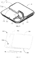
- FIG. 15 is a illustrative structural diagram of the embodiment shown in FIG. 14 after adding a sliding cover, wherein the sliding cover 106 completely covers the box body 200 after returning to its position, so that the packaging box of the disclosure, when closed, can ensure the foodstuff or medicine in the box is fully enclosed and remains clean, and the box surface has no additional raised structure, which facilitates handling, storage and transportation.
- the term "a plurality of” refers to two or more than two, and unless otherwise definite defined, an orientation or positional relationship indicated by the terms such as “above”, “below” is the orientation or positional relationship based on the accompanying drawings only for the convenience of describing the disclosure and simplifying the description, rather than indicating or implying that the indicated device or element must have a specific orientation, be constructed and operated in a specific orientation, therefore, they should not be construed as a limitation of the disclosure; the terms such as “connected”, “installed”, “fixed” shall be understood in a broad sense, for example, “connected” can be a fixed connection, a detachable connection, or an integral connection; it can be a direct connection, or an indirect connection through an intermediate media are indirectly connected. Those of ordinary skill in the art can understand the specific meanings of the above terms in the disclosure according to specific situations.
Landscapes
- Engineering & Computer Science (AREA)
- Mechanical Engineering (AREA)
- Closures For Containers (AREA)
Abstract
Description
- The disclosure relates to the technical field of packaging, in particular, to a cover assembly and a packaging box.
- Packaging boxes are very common in daily life and can be used to store candies and other foods, which are convenient for users to carry around. In the related art, the packaging box usually directly opens or closes the discharge port through a sliding cover, the sealing method of which results in poor sealing effect of the discharge port. In addition, the structure of the cover assembly of the packaging box in the related art is complicated, which is inconvenient for processing and manufacturing.
- The disclosure is intended to solve at least one of the technical problems existing in the prior art.
- To realize this object, a first aspect of the disclosure provides a cover assembly.
- A second aspect of the disclosure provides a packaging box.
- The first aspect of the disclosure provides a cover assembly comprising: a shield provided with an opening; a sliding cover slidably arranged on the shield; a lid located between the shield and the sliding cover and rotatably connected to the shield, so that the opening can be opened or closed under the drive of the sliding cover.
- The disclosure provides a cover assembly which comprises a shield, a sliding cover and a lid. Wherein, the shield is provided with an opening which can be used as a discharge port when the cover assembly is installed to the box body of the packaging box; the lid is arranged at the position of the opening, and the sliding cover is slidably installed on the shield and can drive the lid to move during the sliding process, so that the lid opens or closes the opening.
- Specifically, when the sliding cover slides in one direction, the sliding cover can drive the lid to move during the sliding process, so that the lid opens the opening on the shield, and then candies, medicine and other foodstuff in the box body can be taken out from the opening. When the sliding cover slides in another direction, the sliding cover can drive the lid to move during the sliding process, so that the lid closes the opening on the shield, and then the foodstuff can be prevented from being exposed from the box body.
- In addition, the disclosure drives the lid to move by means of the sliding cover during the sliding process, so as to open or close the opening. On the one hand, effectively sealing of the opening can be realized by utilizing the lid, which avoids the exposure of stuff in the box body of the packaging box, on the other hand, the lid can be driven by utilizing the sliding cover directly, which simplifies the overall structure and can reduce the number of parts of the cover assembly, thereby resulting in a compact structure of the packaging box adopting the cover assembly and can reduce the cost of the cover assembly at the same time. In addition, the opening or closing of the opening on the shield by way of sliding conforms to a user's using habits, facilitates the user's daily operation, and is very compact and convenient. Moreover, compared with the existing structure which usually requires the user to operate with both hands, the cover assembly of the disclosure requires only one hand to open or close the opening, providing the user with an interesting and dynamic way of opening and closing.
- The cover assembly provided by the disclosure can directly drive the lid to move through the sliding cover during the sliding process, so that the lid can open or close the opening, with the whole structure being small and delicate, easy to operate for the user, and at the same time reducing the cost of the cover assembly to ensure the storage of foodstuff inside the box body of the packaging box.
- The cover assembly according to the above technical solution of the disclosure may also have the following additional technical features:
In the above technical solution, the lid comprises: a lid body; a first rotating shaft arranged on the lid body and rotatably connected to the shield; a raised portion arranged on a wall surface of the lid facing the sliding cover; wherein the raised portion can be pushed by the sliding cover when the sliding cover slides in one direction, so as to drive the lid body to open the opening, and the lid body can be pushed by the sliding cover when the sliding cover slides in the opposite direction, so as to drive the lid body to close the opening. - In this technical solution, the lid comprises a lid body, a first rotating shaft and a raised portion. Wherein, the first rotating shaft is arranged on the lid body and is rotatably connected to the shield, so that the lid body is rotatably arranged above the opening; the raised portion is arranged on a wall surface of the lid body facing the sliding cover and is arranged protruding from the lid body to ensure that the raised portion can be pushed by the sliding cover during its sliding in one direction therein, and further the raised portion is driven to drive the lid body to rotate, and thereby open the opening on the shield; when the opening is in an open state, the lid body is in an upright state, and the lid body can be pushed during the sliding of the sliding cover in the other direction, thereby the lid body is driven to close the opening.
- In any of the above technical solutions, the lid further comprises a second rotating shaft protruding from the raised portion; the shield is provided with a guide groove, and the second rotating shaft is located in the guide groove when the lid body opens the opening.
- In this technical solution, the lid further comprises a second rotating shaft, and the shield is provided with a guide groove that is used in cooperation with the second rotating shaft. Wherein, the second rotating shaft is arranged protruding from the side wall of the raised portion, and when the lid body opens the opening, the second rotating shaft is located in the guide groove and abuts against the inner wall of the guide groove, so as to play a role of supporting the lid body and ensure that the lid body is stably in an upright state.
- In any of the above technical solutions, when the lid body closes the opening, the angle formed between the lid body and the plane where the opening lies is less than or equal to 90°; wherein the opening and the angle are located on the same side of the lid body.
- In this technical solution, when the lid body opens the opening at the maximum opening angle, the lid body is in an upright state and forms an angle with the plane where the opening lies, which is less than or equal to 90°. In this way, it can be ensured that in the open state, the inclination angle of the lid body relative to the plane where the opening lies is less than or equal to 90°, ensuring that the lid body can be back in position smoothly when the sliding cover slides towards the other direction of the shield. Specifically, the opening and the angle are located on the same side of the lid body, that is, the above angle can be understood as the maximum rotation angle of the lid body.
- In any of the above technical solutions, when the lid body closes the opening, the angle formed between the lid body and the plane where the opening lies is greater than 90°; wherein the opening and the angle are located on the same side of the lid body.
- In this technical solution, when the lid body opens the opening at the maximum opening angle, the lid body is in an upright state and forms an angle with the plane where the opening lies, which is greater than 90°. In this way, it can be ensured that there is sufficient space between the lid body in the upright state and the plane where the opening lies, which is more beneficial to taking out the stuff such as candies and medicine in the box body, and is convenient for operation. Specifically, the opening and the angle are located on the same side of the lid body, that is, the above angle can be understood as the maximum rotation angle of the lid body. In any of the above technical solutions, the shield is provided with a receiving groove, and the opening is provided on the bottom wall of the receiving groove; the lid body can be received in the receiving groove, and the raised portion is located outside the receiving groove.
- In this technical solution, the shield is provided with a receiving groove. Wherein, the opening is arranged on the bottom wall of the receiving groove. When the lid body closes the opening on the shield, the lid body and the first rotating shaft are both located inside the receiving groove, which ensures the miniaturization and slim design of the cover assembly on the one hand, and avoids the lid body and the first rotating shaft from affecting the sliding of the sliding cover on the other hand.
- In addition, when the lid body closes the opening on the shield, the raised portion is located outside the receiving groove to ensure that the raised portion can be pushed by the sliding cover during the sliding process, so as to ensure that the sliding cover can drive the lid body to rotate to open the opening on the shield by means of the raised portion.
- In any of the above technical solutions, the shield comprises: a shield body on which the opening is provided; a moving element arranged on the side of the shield body facing the sliding cover, and the sliding cover is arranged over the moving element and is slidably connected to the moving element.
- In this technical solution, the shield comprises a shield body and a moving element. Wherein, the shield body is provided with the above opening, the moving element is arranged on the shield body and is located on a side of the shield body facing the sliding cover; the sliding cover is arranged over the moving element and can be directly slidably connected to the moving element, ensuring that the sliding cover can be pushed by the user. In addition, the moving element located under the sliding cover can further play a role of supporting the sliding cover, preventing the sliding cover from being dented and deformed due to the collision of external force and ensuring the service life of the cover assembly.
- In any of the above technical solutions, the side wall of the moving element is provided with a guide protrusion or guide slot which extends along the sliding direction of the sliding cover; the sliding cover has a peripheral edge which is slidably connected to the guide protrusion or guide slot.
- In this technical solution, the side wall of the moving element is provided with a guide protrusion or a guide slot, and the sliding cover has a peripheral edge. Wherein, the guide protrusion or guide slot extends along the sliding direction of the sliding cover, while the peripheral edge of the sliding cover is slidably connected to the guide protrusion or guide slot, which ensures that the sliding cover can slide along the extending direction of the guide protrusion or guide slot, and further ensures the position limiting between the sliding cover and the moving element in the thickness direction of the cover assembly, and prevents the sliding cover from breaking away from the moving element during use.
- In any of the above technical solutions, the moving element is located on the side of the opening; the moving element has an abutting surface on the side facing the opening, and the sliding cover can abut against the abutting surface.
- In this technical solution, the moving element is located on the side of the opening, and the moving element is provided with an abutting surface. Wherein, the abutting surface is located on a side of the moving element facing the opening, and can be used for limiting the abutting position of the sliding cover.
- Specifically, the sliding cover slides towards one direction of the shield, and drives the lid to move during the sliding process, so that the lid opens the opening on the shield, and then the sliding cover slides to the farthest distance and abuts against the abutting surface, ensuring that the abutting surface limits the sliding travel of the sliding cover to avoid damage to the lid due to excessive sliding of the sliding cover.
- In any of the above technical solutions, the shield further comprises: a clamping portion protruding from the side of the shield body facing the sliding cover, and the clamping portion is arranged away from the moving element, and the sliding cover can be clamped on the clamping portion.
- In this technical solution, the shield further comprises a clamping portion. Wherein, the clamping portion is arranged on a side of the shield body facing the sliding cover, and is arranged protruding from the shield body. The clamping portion and the moving element are located on opposite sides of the lid, and the sliding cover can be clamped on the clamping portion.
- Specifically, when the lid closes the opening, the sliding cover is clamped on the clamping portion, thereby ensuring the role of positioning the sliding cover, avoiding accidental sliding of the sliding cover, and preventing the sliding cover from breaking away from the moving element due to excessive sliding.
- In any of the above technical solutions, the shield body, the moving element and the clamping portion are of an integrated structure.
- In this technical solution, the shield body, the moving element and the clamping portion are of an integrated structure, and can be integrally processed and formed. In this way, on the one hand, the manufacturing process of the shield can be reduced, and on the other hand, the strength of the shield itself can be ensured, so as to ensure the service life of the cover assembly.
- In any of the above technical solutions, the lid body, the first rotating shaft, the raised portion and the second rotating shaft are of an integrated structure.
- In this technical solution, the lid body, the first rotating shaft, the raised portion and the second rotating shaft are of an integrated structure, which can be integrally processed and formed and assembled to the shield. In this way, on the one hand, the manufacturing process of the lid can be reduced, and on the other hand, the strength of the lid itself can be ensured, so as to ensure the service life of the cover assembly.
- In any of the above technical solutions, the cover assembly further comprises: a decoration portion arranged on a wall surface of the sliding cover away from the shield.
- In this technical solution, the cover assembly further comprises a decoration portion. Wherein, the decoration portion is arranged on a wall surface of the sliding cover away from the shield, so as to enhance the appearance aesthetics of the cover assembly, and at the same time, it serves as a mark for distinguishing.
- Specifically, a decoration layer can be adopted for the decoration portion and cover the wall surface of the sliding cover away from the shield, and the decoration layer can be provided with commodity information and patterns, etc.
- In any of the above technical solutions, the shield is a plastic piece.
- In this technical solution, the shield may adopt a plastic piece. Wherein, the plastic piece has good plasticity, and can provide a good insulating effect between the sliding cover and the box body of the packaging box, especially when the box body and the sliding cover both adopt metal pieces, avoid rigid contact, and at the same time eliminate the noise during the sliding process of the sliding cover.
- In any of the above technical solutions, the sliding cover is a metal piece.
- In this technical solution, the sliding cover is a metal piece. The metal piece has good rigidity and hardness, which can bear larger external force, avoid the deformation or depression of the sliding cover due to the collision of external force, and ensure the service life of the cover assembly.
- In any of the above technical solutions, the lid is a plastic piece.
- In this technical solution, the lid is a plastic piece. Plastic pieces have good shaping and sealing properties. In this way, on the one hand, it can ensure that no noise will occur due to collision when the lid opens and closes the opening, on the other hand, it ensures the sealing of the opening, which in turn ensures the preservation effect of the foodstuff inside the box.
- A second aspect of the disclosure provides a packaging box comprising: a box body having a cavity; a cover assembly according to the first aspect of the disclosure, wherein the shield is connected to the box body, and the opening is communicated to the cavity.
- The packaging box provided by the disclosure comprises a box body and the cover assembly according to any of the above technical solutions. Therefore, the packaging box has all the beneficial effects of the above cover assembly, which will not be discussed again herein.
- Specifically, the box body has a cavity which can be used to store stuff such as candies and medicine. The shield is connected to the box body, and the opening on the shield is communicated to the cavity of the box body. Driving the sliding cover to slide enables the lid to open or close the opening on the shield, so that the user can take out foodstuff from the cavity.
- Additional aspects and advantages of the disclosure will become apparent in the description sections that follow or will be learned through the practice of the disclosure.
- The above and/or additional aspects and advantages of the disclosure will become apparent and readily understood in combination with the description of embodiments in the following accompanying drawings, wherein:
-
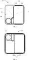
FIG. 1 is an illustrative structural diagram of a cover assembly according to one embodiment of the disclosure (not showing the sliding cover); -
FIG. 2 is an illustrative structural diagram of a cover assembly according to one embodiment of the disclosure (not showing the lid); -
FIG. 3 is a top view of the cover assembly shown inFIG. 1 ; -
FIG. 4 is a bottom view of the cover assembly shown inFIG. 1 ; -
FIG. 5 is a side view of the cover assembly shown inFIG. 1 ; -
FIG. 6 is a cross-sectional view of the cover assembly shown inFIG. 5 taken along A-A; -
FIG. 7 is a schematic structural diagram of a lid in the cover assembly shown inFIG. 1 ; -
FIG. 8 is a side view of the lid shown inFIG. 7 ; -
FIG. 9 is a top view of the lid shown inFIG. 7 ; -
FIG. 10 is a front view of the lid shown inFIG. 7 ; -
FIG. 11 is a cross-sectional view of the lid shown inFIG. 9 taken along B-B; -
Fig. 12 is a partial enlarged view of part C of the cover assembly shown inFig. 6 ; -
Fig. 13 is a partial enlarged view of part D of the cover assembly shown inFig. 5 ; -
FIG. 14 is an illustrative structural diagram of a packaging box according to one embodiment of the disclosure; -
FIG. 15 is an illustrative structural diagram the embodiment shown inFIG. 14 after adding a sliding cover. - Among them, the corresponding relationship between the reference numerals and the component names in
FIG. 1 to FIG. 15 is:
100 cover assembly, 102 shield, 104 opening, 106 sliding cover, 108 lid, 110 lid body, 112 first rotating shaft, 114 raised portion, 116 second rotating shaft, 118 guide groove, 120 receiving groove, 122 shield body, 124 moving element, 126 guide protrusion, 128 peripheral edge, 130 clamping portion, 132 abutting surface, 200 box body. - In order to be able to understand the above object, features and advantages of the disclosure more clearly, the disclosure will be further described in detail below with reference to the accompanying drawings and specific embodiments. It should be noted that, in the event of no conflict, features in the same embodiment and different embodiments of the disclosure may be combined with each other.
- Many specific details are set forth in the following description to facilitate a full understanding of the disclosure. However, the disclosure can also be implemented in other ways different from those described herein. Therefore, the protection scope of the disclosure is not limited by the specific embodiments disclosed below.
- The
cover assembly 100 and the packaging box provided according to some embodiments of the disclosure will be described below with reference toFIGS. 1 to 14 . The solid arrow inFIG. 2 indicates the sliding direction of the slidingcover 106 when theopening 104 is being opened, and the dashed arrow indicates the sliding direction of the slidingcover 106 when theopening 104 is being closed. - As shown in
FIGS. 1 and 2 , the first embodiment of the disclosure provides acover assembly 100 which comprises acover 102, a slidingcover 106 and alid 108. - Wherein, the
shield 102 is provided with anopening 104 which can be used as a discharge port when thecover assembly 100 is installed to thebox body 200 of the packaging box; thelid 108 is arranged at the position of theopening 104, and the slidingcover 106 is slidably installed on theshield 102 and can drive thelid 108 to move during the sliding process, so that thelid 108 opens or closes theopening 104. - Specifically, as shown in
FIG. 2 , when the slidingcover 106 slides in the direction indicated by the solid arrow, the slidingcover 106 can drive thelid 108 to move during the sliding process, so that thelid 108 opens theopening 104 on theshield 102, and then the stuff can be taken out from theopening 104. When the slidingcover 106 slides in the direction indicated by the dashed arrow, the slidingcover 106 can drive thelid 108 to move during the sliding process, so that thelid 108 closes theopening 104 on theshield 102, and then the stuff can be prevented from exposed from inside of thebox body 200 of the packaging box. - In addition, in this embodiment, the
lid 108 is driven to move by the slidingcover 106 during the sliding process, so as to open or close theopening 104. On the one hand, effectively sealing of theopening 104 can be realized by utilizing thelid 108, which facilitates the storage of stuff in thebox body 200 of the packaging box, on the other hand, thelid 108 can be driven by utilizing the slidingcover 106 directly, which simplifies the overall structure and can reduce the number of parts of thecover assembly 100, thereby resulting in a compact structure of the packaging box adopting thecover assembly 100 and can reduce the cost of thecover assembly 100 at the same time. - In addition, the opening or closing of the
opening 104 on theshield 102 by way of sliding conforms to a user's using habits, facilitates the user's daily operation, and is very compact and convenient. Moreover, compared with the existing structure which usually requires the user to operate with both hands, thecover assembly 100 of the disclosure requires only one hand to open or close theopening 104, providing the user with an interesting and dynamic way of opening and closing. - Therefore, the
cover assembly 100 provided by the embodiment can directly drive thelid 108 to move through the slidingcover 106 during the sliding process, so that the lid can open or close the opening, with the whole structure being small and delicate, easy to operate for the user, and at the same time reducing the cost of the cover assembly to ensure the storage of foodstuff inside the box body of the packaging box. - The second embodiment of the disclosure provides a
cover assembly 100 on the basis of the first embodiment, which further provides:
As shown inFIGS. 7 ,8 ,9 ,10 and 11 , thelid 108 comprises alid 110, a firstrotating shaft 112 and a raisedportion 114. The firstrotating shaft 112 is arranged on thelid body 110 and is rotatably connected to theshield 102, so that thelid body 110 is rotatably arranged above theopening 104; the raisedportion 114 is arranged on a side of thelid body 110 facing the slidingcover 106 and is arranged protruding from thelid body 110 to ensure that the raisedportion 114 can be pushed by the slidingcover 106 during its sliding in the direction indicated by the solid arrow, and then the raisedportion 114 is driven to drive thelid body 110 to rotate, so that thelid body 110 opens theopening 104 on theshield 102; when theopening 104 is in the open state, thelid body 110 is in an upright state, and thelid body 110 can be pushed during the sliding process of the sliding cover in the other direction, so that thelid body 110 is driven to close theopening 104. - Specifically, as shown in
FIG. 2 , when the slidingcover 106 slides in the direction indicated by the solid arrow, the slidingcover 106 can push one side of the raisedportion 114 during the sliding process, and at this time the raisedportion 114 drives thelid body 110 to rotate to one side, and thelid body 110 opens theopening 104 on theshield 102; when theopening 104 is in the open state, thelid body 110 is in an upright state, while the raisedportion 114 is in a horizontally arranged state; when the slidingcover 106 slides in the direction indicated by the solid arrow, the slidingcover 106 can pushed thelid body 110 during the sliding process, and at this time thelid body 110 rotates toward the other side, and thelid body 110 closes theopening 104 on theshield 102. - In this embodiment, further, as shown in
FIG. 3 , thelid 108 further comprises a secondrotating shaft 116, and theshield 102 is provided with aguide groove 118 that is used in cooperation with the secondrotating shaft 116. The secondrotating shaft 116 is arranged protruding from the side wall of the raisedportion 114, and when thelid body 110 opens theopening 104, the secondrotating shaft 116 is located in theguide groove 118 and abuts against the inner wall of theguide groove 118, so as to play the role of supporting thelid body 110 and ensure that thelid body 110 is stably in an upright state. - In a specific embodiment, as shown in
FIG. 1 , when thelid body 110 opens theopening 104 at the maximum opening angle, thelid body 110 is in an upright state, and an angle α is formed between thelid body 110 and the plane where theopening 104 lies, which is less than or equal to 90°. In this way, it ensures that in the open state, the inclination angle of thelid body 110 relative to the plane where theopening 104 lies is less than or equal to 90°, ensuring that thelid body 110 can be back in position smoothly when the slidingcover 106 slides towards the other direction of theshield 102. - In a specific embodiment, when the
lid body 110 opens theopening 104 at the maximum opening angle, thelid body 110 is in an upright state and forms an angle α with the plane where theopening 104 lies, which is greater than 90°. In this way, sufficient space can between thelid body 110 in the upright state and the plane where theopening 104 lies, which is more beneficial to taking out the stuff such as candies and medicine in thebox body 200, and is convenient for operation. - Specifically, the
opening 104 and the angle α are located on the same side of thelid body 110, that is, the above angle α can be understood as the maximum rotation angle of thelid body 110. Specifically, the plane where theopening 104 lies is the end surface of theshield body 122. - In this embodiment, further, as shown in
FIG. 7 ,FIG. 8 ,FIG. 9 ,FIG. 10 and FIG. 11 , thelid body 110, the firstrotating shaft 112, the raisedportion 114 and the secondrotating shaft 116 are of an integrated structure, which can be integrally processed and formed and assembled to theshield 102. In this way, on the one hand, the manufacturing process of thelid 108 can be reduced, and on the other hand, the strength of thelid 108 itself can be ensured, so as to ensure the service life of thecover assembly 100. - The third embodiment of the disclosure provides a
cover assembly 100 on the basis of the first embodiment, which further provides:
As shown inFIG. 1 , theshield 102 is provided with a receivinggroove 120. Wherein, theopening 104 is arranged on the bottom wall of the receivinggroove 120. When thelid body 110 closes theopening 104 on theshield 102, thelid body 110 and the firstrotating shaft 112 are both located inside the receivinggroove 120, which ensures the miniaturization and slim design of thecover assembly 100 on the one hand, and avoids thelid body 110 and the firstrotating shaft 112 from affecting the sliding of the slidingcover 106 on the other hand. - In addition, when the
lid body 110 closes theopening 104 on theshield 102, the raisedportion 114 is located outside the receivinggroove 120 to ensure that the raisedportion 114 can be pushed by the slidingcover 106 during the sliding process, so as to ensure that the slidingcover 106 can slide through the raisedportion 114 to drive thelid body 110 to rotate to open theopening 104 on theshield 102. - The fourth embodiment of the disclosure provides a
cover assembly 100 on the basis of the first embodiment, which further provides:
As shown inFIGS. 3, 4 ,5 and 6 , theshield 102 comprises ashield body 122 and a movingelement 124. Theshield body 122 is provided with theabove opening 104, the movingelement 124 is arranged on theshield body 122 and is located on a side of theshield body 122 facing the slidingcover 106 ; the slidingcover 106 is arranged over the movingelement 124 and can be directly slidably connected to the movingelement 124, ensuring that the slidingcover 106 can be pushed by the user. In addition, the movingelement 124 located under the slidingcover 106 can further play a role of supporting the slidingcover 106, preventing the slidingcover 106 from being dented and deformed due to the collision of external force and ensuring the service life of thecover assembly 100. - In this embodiment, as shown in
FIG. 2 ,FIG. 6 andFIG. 12 , the side wall of the movingelement 124 is further provided with aguide protrusion 126, and the slidingcover 106 has aperipheral edge 128. Wherein, theguide protrusion 126 extends along the sliding direction of the slidingcover 106, and theperipheral edge 128 of the slidingcover 106 is slidably connected to theguide protrusion 126, which ensures that the slidingcover 106 can slide along the extension direction of theguide protrusion 126, and further ensures the position limiting between the slidingcover 106 and the movingelement 124 in the thickness direction of thecover assembly 100, and prevents the slidingcover 106 from breaking away from the movingelement 124 during use. - In another embodiment, a guide slot (not shown in the figure) can also be adopted to replace the
guide protrusion 126, while the edge of the slidingcover 106 adopting a structure matching the guide slot, which can also realize the sliding of the slidingcover 106 along the extension direction of the guide slot, and further ensures the position limiting between the slidingcover 106 and the movingelement 124 and prevents the slidingcover 106 from breaking away from the movingelement 124 during use. - In this embodiment, further, as shown in
FIG. 1 , the movingelement 124 is located on the side of theopening 104, and the movingelement 124 is provided with anabutting surface 132. Wherein, the abuttingsurface 132 is located on a side of the movingelement 124 facing theopening 104, and can be used for limiting the abutting position of the slidingcover 106. - Specifically, as shown in
FIG. 2 , when theopening 104 is to be opened, the slidingcover 106 slides towards one direction of theshield 102, and drives thelid 108 to move during the sliding process, so that thelid 108 opens theopening 104 on theshield 102, and then the slidingcover 106 slides to the farthest distance and abuts against the abuttingsurface 132, ensuring that theabutting surface 132 limits the sliding travel of the slidingcover 106 to avoid damage to thelid 108 due to excessive sliding of the slidingcover 106. - In this embodiment, further, as shown in
FIG. 1 ,FIG. 3 ,FIG. 5 andFIG. 13 , theshield 102 further comprises a clampingportion 130. Wherein, the clampingportion 130 is arranged on a wall surface of theshield body 122 facing the slidingcover 106 and is arranged protruding from theshield body 122. The clampingportion 130 and the movingelement 124 are located on opposite sides of thelid 108, and the slidingcover 106 can be clamped on the clampingportion 130. - Specifically, when the
lid 108 closes theopening 104, the slidingcover 106 is clamped on the clampingportion 130, thereby ensuring the role of positioning the slidingcover 106 and preventing the slidingcover 106 from sliding accidentally. - In this embodiment, further, as shown in
FIG. 5 and FIG. 6 , theshield body 122, the movingelement 124 and the clampingportion 130 are of an integrated structure, and can be integrally processed and formed. In this way, on the one hand, the manufacturing process of theshield 102 can be reduced, and on the other hand, the strength of theshield 102 itself can be ensured, so as to ensure the service life of thecover assembly 100. - The fifth embodiment of the disclosure provides a
cover assembly 100 on the basis of the first embodiment, which further provides:
Thecover assembly 100 further comprises a decoration portion (not shown in the figure). Wherein, the decoration portion is arranged on the side of the slidingcover 106 away from theshield 102, so as to enhance the appearance aesthetics of thecover assembly 100, and at the same time, it serves as a mark for distinguishing. - Specifically, a decoration layer can be adopted for the decoration portion and cover the side of the sliding
cover 106 away from theshield 102, and the decoration layer can be provided with commodity information and patterns, etc. - On the basis of the first embodiment to the fifth embodiment, further, the
shield 102 can adopt a plastic piece. Wherein, the plastic piece has good plasticity, and can provide a good insulating effect between the sliding cover and thebox body 200 of the packaging box, especially when thebox body 200 and the slidingcover 106 both adopt metal pieces, avoid rigid contact, and at the same time eliminate the noise during the sliding process of the slidingcover 106. - On the basis of the first embodiment to the fifth embodiment, further, the sliding
cover 106 is a metal piece. The metal piece has good rigidity and hardness, which can bear larger external force, avoid the deformation or depression of the slidingcover 106 due to the collision of external force, and ensure the service life of thecover assembly 100. - On the basis of the first embodiment to the fifth embodiment, further, the
lid 108 is a plastic piece. Plastic pieces have good shaping and sealing properties. In this way, on the one hand, it can ensure that thelid 108 will not generate noise due to collision when opening and closing theopening 104, and on the other hand, the sealing of theopening 104 can be ensured, thereby ensuring the preservation effect of the food in thebox body 200. - As shown in
FIG. 14 , the sixth embodiment of the disclosure provides a packaging box provided by the disclosure, which comprises abox body 200 and thecover assembly 100 of any of the above embodiments. - The packaging box provided by the embodiment of the disclosure comprises the
cover assembly 100 of any of the above embodiments. Therefore, all the beneficial effects of thecover assembly 100 described above will not be further discussed here one by one. - Specifically, as shown in
FIG. 14 , thebox body 200 has a cavity which can be used to store stuff such as candies and medicine. Theshield 102 is connected to thebox body 200, and theopening 104 on theshield 102 is communicated to the cavity of thebox body 200. Driving the sliding cover to slide enables thelid 108 to open or close theopening 104 on theshield 102, so that the user can take out foodstuff from the cavity. - In a specific embodiment, the
box body 200 is a metal piece. In this way, the slidingcover 106 and thebox body 200 are both metal pieces, which ensures the strength and service life of the packaging box. Theshield 102 adopts a plastic piece, and is located between thebox body 200 and the slidingcover 106, and plays a role of good cushioning transition. - As shown in
FIG. 14 , the first specific embodiment of the disclosure provides a packaging box, which can be used to store foodstuff such as candies. Wherein, the packaging box comprises acover assembly 100 and abox body 200. - Specifically, as shown in
FIGS. 1, 2 ,3 and 4 , thecover assembly 100 comprises ashield 102, a slidingcover 106 and alid 108. Theshield 102 is provided with anopening 104, thelid 108 is arranged at the position of theopening 104, the slidingcover 106 is slidably installed on theshield 102, and can drive thelid 108 to move during the sliding process, so that thelid 108 opens or closes theopening 104. - Specifically, as shown in
FIGS. 7 ,8 ,9 ,10 and 11 , thelid 108 comprises alid 110, a firstrotating shaft 112, a raisedportion 114 and a secondrotating shaft 116. Thelid body 110 is rotatably connected to theshield 102 through the firstrotating shaft 112, and is rotatably arranged over theopening 104; the raisedportion 114 protrudes from the side of thelid body 110 facing the slidingcover 106, which ensures that the raisedportion 114 can be pushed by the slidingcover 106 during its sliding in direction indicated by the solid arrow, and then the raisedportion 114 is driven to drive thelid body 110 to rotate, so that thelid body 110 opens theopening 104 on theshield 102; when theopening 104 is in the open state, thelid body 110 is in an upright state, and thelid body 110 can be pushed during the sliding process of the sliding cover in the other direction, so that thelid body 110 is driven to close theopening 104. - In addition, the second
rotating shaft 116 cooperates with theguide groove 118 on theshield 102 to ensure the rotation angle of thelid body 110. Specifically, when thelid body 110 closes theopening 104, the secondrotating shaft 116 is located in theguide groove 118, and thelid body 110 is in an upright state. At this time, an angle α is formed between thelid body 110 and the plane where theopening 104 lies, and the angle α may be less than or equal to 90° to ensure that thelid body 110 can be back in position smoothly. In addition, the angle α can also be greater than 90°, which is more conducive to taking out the stuff such as candies and medicine in thebox body 200 and is convenient for operation. - Specifically, as shown in
FIG. 1 , theshield 102 is provided with a receivinggroove 120, and theopening 104 is provided on the bottom wall of the receivinggroove 120. When thelid body 110 closes theopening 104 on theshield 102, thelid body 110 and the firstrotating shaft 112 are both located inside the receivinggroove 120, and the raisedportion 114 is located outside the receivinggroove 120. - Specifically, as shown in
FIGS. 5 and 6 , theshield 102 comprises ashield body 122 and a movingelement 124. Theshield body 122 is provided with theabove opening 104, and the slidingcover 106 is arranged over the movingelement 124 and can be slidably connected to the movingelement 124 directly. Wherein, the side wall of the movingelement 124 is provided with aguide protrusion 126 or a guide slot, the slidingcover 106 has aperipheral edge 128, and theperipheral edge 128 of the slidingcover 106 is slidably connected to theguide protrusion 126 or the guide slot, which ensures that the slidingcover 106 can slide along the extending direction of theguide protrusion 126, and further ensures the position limiting between the slidingcover 106 and the movingelement 124 in the thickness direction of thecover assembly 100 at the same time, and prevents the slidingcover 106 from breaking away from the movingelement 124 during use. - Specifically, as shown in
FIG. 1 , the movingelement 124 is located on a side of theopening 104, and the movingelement 124 is provided with anabutting surface 132 which is located on the side of the movingelement 124 facing theopening 104, which can realize the abutting position limit on one side of the slidingcover 106. As shown inFIG. 13 , the wall surface of theshield body 122 facing the slidingcover 106 is provided with the clampingportion 130. - Specifically, the
lid body 110, the firstrotating shaft 112, the raisedportion 114 and the secondrotating shaft 116 are of an integral structure. - Specifically, the
shield body 122, the movingelement 124 and the clampingportion 130 are of an integral structure. - Specifically, the
cover assembly 100 further comprises a decoration portion. Wherein, a decoration layer can be adopted for the decoration portion and cover the side of the slidingcover 106 away from theshield 102, and the decoration layer can be provided with commodity information and patterns, etc. - Specifically, the
shield 102 is a plastic piece, the slidingcover 106 is a metal piece, thelid 108 is a plastic piece, and thebox body 200 is a metal piece. -
FIG. 15 is a illustrative structural diagram of the embodiment shown inFIG. 14 after adding a sliding cover, wherein the slidingcover 106 completely covers thebox body 200 after returning to its position, so that the packaging box of the disclosure, when closed, can ensure the foodstuff or medicine in the box is fully enclosed and remains clean, and the box surface has no additional raised structure, which facilitates handling, storage and transportation. - In the description of the disclosure, the term "a plurality of" refers to two or more than two, and unless otherwise definite defined, an orientation or positional relationship indicated by the terms such as "above", "below" is the orientation or positional relationship based on the accompanying drawings only for the convenience of describing the disclosure and simplifying the description, rather than indicating or implying that the indicated device or element must have a specific orientation, be constructed and operated in a specific orientation, therefore, they should not be construed as a limitation of the disclosure; the terms such as "connected", "installed", "fixed" shall be understood in a broad sense, for example, "connected" can be a fixed connection, a detachable connection, or an integral connection; it can be a direct connection, or an indirect connection through an intermediate media are indirectly connected. Those of ordinary skill in the art can understand the specific meanings of the above terms in the disclosure according to specific situations.
- In the description of the specification, the description of the terms such as "one embodiment", "some embodiments", "specific embodiment" means that a particular feature, structure, material or characteristic described in connection with the embodiment or example is included in at least one embodiment or example of the disclosure. In the specification, schematic representations of the above terms do not necessarily refer to the same embodiment or example. Furthermore, the specific features, structures, materials or characteristics described may be combined in a suitable manner in any one or more embodiments or examples.
- The above are only preferred embodiments of the disclosure, and are not intended to limit the disclosure. For those skilled in the art, the disclosure may have various modifications and changes. Any modification, equivalent replacement, improvement, etc. made within the spirit and principle of the disclosure shall be included within the protection scope of the disclosure.
Claims (15)
- A cover assembly (100) comprising:a shield (102) provided with an opening (104);a sliding cover (106) slidably arranged on the shield (102);a lid (108) positioned between the shield (102) and the sliding cover (106), and rotatably connected to the shield (102), so as to open or close the opening (104) under the drive of the sliding cover (106).
- The cover assembly (100) according to claim 1, wherein the lid (108) comprises:a lid body (110);a first rotating shaft (112) arranged on the lid body (110) and rotatably connected to the shield (102);a raised portion (114) arranged on a side of the lid body (110) facing the sliding cover (106);wherein the raised portion (114) can be pushed by the sliding cover (106) when the sliding cover (106) slides in one direction, so as to drive the lid body (110) to open the opening (104), and the lid body (110) can be pushed by the sliding cover (106) when the sliding cover (106) slides in the opposite direction, so as to drive the lid body (110) to close the opening (104).
- The cover assembly (100) according to claim 2, wherein:the lid (108) further comprises a second rotating shaft (116) protruding from the raised portion (114);the shield (102) is provided with a guide groove, and the second rotating shaft (116) is located in the guide groove when the lid body (110) opens the opening (104).
- The cover assembly (100) according to claim 3, wherein:an angle formed between the lid body (110) and a plane where the opening (104) lies is less than or equal to 90° when the lid body (110) is at the maximum opening angle;wherein, the opening (104) and the angle are located on the same side of the lid body (110).
- The cover assembly (100) according to claim 3, wherein:an angle formed between the lid body (110) and a plane where the opening (104) lies is greater than 90° when the lid body (110) is at the maximum opening angle;wherein, the opening (104) and the angle are located on the same side of the lid body (110).
- The cover assembly (100) according to claim 2, wherein:the shield (102) is provided with a receiving groove (120), and the opening (104) is provided on a bottom wall of the receiving groove (120);the lid body (110) can be received in the receiving groove (120), and the raised portion (114) is outside the receiving groove (120).
- The cover assembly (100) according to any one of claims 2 to 6, wherein the shield (102) comprises:a shield body (122) on which the opening (104) is arranged;a moving element (124) arranged on a side of the shield body (122) facing the sliding cover (106), and the sliding cover (106) is arranged over the moving element (124) and is slidably connected to the moving element (124).
- The cover assembly (100) according to claim 7, wherein:the moving element (124) is provided with a guide protrusion (126) or a guide slot, and the guide protrusion (126) or the guide slot extends along the sliding direction of the sliding cover (106);the sliding cover (106) has a peripheral edge slidably connected to the guide protrusion (126) or the guide slot.
- The cover assembly (100) according to claim 7, wherein:the moving element (124) is located on a side of the opening (104);the moving element (124) has an abutting surface (132) on a side facing the opening (104), and the sliding cover (106) can abut against the abutting surface (132).
- The cover assembly (100) according to claim 7, wherein the shield (102) further comprises:
a clamping portion (130) protruding from a side of the shield body (122) facing the sliding cover (106), and the clamping portion (130) is arranged away from the moving element (124), and the sliding cover (106) is clampable to the clamping portion (130). - The cover assembly (100) according to claim 10, wherein:
the shield body (122), the moving element (124) and the clamping portion (130) are of an integrated structure. - The cover assembly (100) according to claim 3, wherein:
the lid body (110), the first rotating shaft (112), the raised portion (114) and the second rotating shaft (116) are of an integral structure. - The cover assembly (100) according to any one of claims 1 to 6, further comprising:
a decoration portion arranged on a side of the sliding cover (106) away from the shield (102). - The cover assembly (100) according to any one of claims 1 to 6, further comprising:the shield (102) is a plastic piece; and/orthe sliding cover (106) is a metal piece; and/orthe lid (108) is a plastic piece.
- A packaging box comprising:a box body (200) having a cavity;the cover assembly (100) according to one of claims 1 to 14, wherein the shield (102) is connected to the box body (200), and the opening (104) is communicated to the cavity.
Applications Claiming Priority (1)
| Application Number | Priority Date | Filing Date | Title |
|---|---|---|---|
| CN202110451491.1A CN115246526A (en) | 2021-04-26 | 2021-04-26 | Cover body assembly and packaging box |
Publications (2)
| Publication Number | Publication Date |
|---|---|
| EP4082931A1 true EP4082931A1 (en) | 2022-11-02 |
| EP4082931B1 EP4082931B1 (en) | 2024-06-05 |
Family
ID=81387036
Family Applications (1)
| Application Number | Title | Priority Date | Filing Date |
|---|---|---|---|
| EP22170029.7A Active EP4082931B1 (en) | 2021-04-26 | 2022-04-26 | Cover assembly and packaging box |
Country Status (3)
| Country | Link |
|---|---|
| US (1) | US11919681B2 (en) |
| EP (1) | EP4082931B1 (en) |
| CN (1) | CN115246526A (en) |
Citations (2)
| Publication number | Priority date | Publication date | Assignee | Title |
|---|---|---|---|---|
| WO2008024358A2 (en) * | 2006-08-21 | 2008-02-28 | Meadwestvaco Corporation | Container with sliding cover panel |
| US20100213221A1 (en) * | 2009-02-23 | 2010-08-26 | Gateway Plastics, Inc. | Closure for a container |
Family Cites Families (4)
| Publication number | Priority date | Publication date | Assignee | Title |
|---|---|---|---|---|
| US20070062964A1 (en) * | 2005-09-20 | 2007-03-22 | Item Source, Llc | Reclosable container with easily openable closure |
| US20080060975A1 (en) * | 2006-08-17 | 2008-03-13 | Young Steve R | Display Package with Extending Trays |
| KR100800410B1 (en) * | 2006-12-29 | 2008-02-01 | (주)쉘-라인 | Cosmetic case |
| CN205671697U (en) * | 2016-04-29 | 2016-11-09 | 南希·沃纳 | Container |
-
2021
- 2021-04-26 CN CN202110451491.1A patent/CN115246526A/en active Pending
-
2022
- 2022-04-25 US US17/728,840 patent/US11919681B2/en active Active
- 2022-04-26 EP EP22170029.7A patent/EP4082931B1/en active Active
Patent Citations (2)
| Publication number | Priority date | Publication date | Assignee | Title |
|---|---|---|---|---|
| WO2008024358A2 (en) * | 2006-08-21 | 2008-02-28 | Meadwestvaco Corporation | Container with sliding cover panel |
| US20100213221A1 (en) * | 2009-02-23 | 2010-08-26 | Gateway Plastics, Inc. | Closure for a container |
Also Published As
| Publication number | Publication date |
|---|---|
| EP4082931B1 (en) | 2024-06-05 |
| CN115246526A (en) | 2022-10-28 |
| US20220340338A1 (en) | 2022-10-27 |
| US11919681B2 (en) | 2024-03-05 |
Similar Documents
| Publication | Publication Date | Title |
|---|---|---|
| US11203466B2 (en) | Storage box | |
| US3532211A (en) | Storage case tape cartridge | |
| US11141349B1 (en) | Structure with lid, and storage container | |
| EP4082931A1 (en) | Cover assembly and packaging box | |
| WO2018121782A1 (en) | Drawer assembly and refrigerator having same | |
| CN104427804A (en) | Door plate device and storage equipment | |
| JP5517236B2 (en) | Container sealing structure | |
| CN215324363U (en) | Cover body assembly and packaging box | |
| CN218493382U (en) | Hinge assembly and refrigerator | |
| CN208603055U (en) | The sliding cigarette box of automatic cover-turning | |
| JP5698970B2 (en) | Sealed compact container | |
| KR100679653B1 (en) | Opening/closing device for a storeroom of door | |
| US6357841B1 (en) | Ejectable compact disc container | |
| WO2019233480A1 (en) | Cigarette packaging structure | |
| CN220683336U (en) | Novel candy packing box | |
| JP6689531B2 (en) | Cup container with lid | |
| JP7363458B2 (en) | Wet tissue packaging container | |
| JPH07169235A (en) | Tape cassette | |
| JP2007200377A5 (en) | ||
| CN220389401U (en) | Tool box cover and tool box | |
| JP5595885B2 (en) | Compact container | |
| CN208435228U (en) | Electric cooker and its casing assembly | |
| CN221749959U (en) | Containing box table | |
| CN213953324U (en) | Limiting assembly, door mechanism and safe | |
| JP3224146U (en) | Seasoning container |
Legal Events
| Date | Code | Title | Description |
|---|---|---|---|
| PUAI | Public reference made under article 153(3) epc to a published international application that has entered the european phase |
Free format text: ORIGINAL CODE: 0009012 |
|
| STAA | Information on the status of an ep patent application or granted ep patent |
Free format text: STATUS: THE APPLICATION HAS BEEN PUBLISHED |
|
| AK | Designated contracting states |
Kind code of ref document: A1 Designated state(s): AL AT BE BG CH CY CZ DE DK EE ES FI FR GB GR HR HU IE IS IT LI LT LU LV MC MK MT NL NO PL PT RO RS SE SI SK SM TR |
|
| STAA | Information on the status of an ep patent application or granted ep patent |
Free format text: STATUS: REQUEST FOR EXAMINATION WAS MADE |
|
| 17P | Request for examination filed |
Effective date: 20230424 |
|
| RBV | Designated contracting states (corrected) |
Designated state(s): AL AT BE BG CH CY CZ DE DK EE ES FI FR GB GR HR HU IE IS IT LI LT LU LV MC MK MT NL NO PL PT RO RS SE SI SK SM TR |
|
| GRAP | Despatch of communication of intention to grant a patent |
Free format text: ORIGINAL CODE: EPIDOSNIGR1 |
|
| STAA | Information on the status of an ep patent application or granted ep patent |
Free format text: STATUS: GRANT OF PATENT IS INTENDED |
|
| INTG | Intention to grant announced |
Effective date: 20231220 |
|
| GRAS | Grant fee paid |
Free format text: ORIGINAL CODE: EPIDOSNIGR3 |
|
| P01 | Opt-out of the competence of the unified patent court (upc) registered |
Effective date: 20240325 |
|
| GRAA | (expected) grant |
Free format text: ORIGINAL CODE: 0009210 |
|
| STAA | Information on the status of an ep patent application or granted ep patent |
Free format text: STATUS: THE PATENT HAS BEEN GRANTED |
|
| AK | Designated contracting states |
Kind code of ref document: B1 Designated state(s): AL AT BE BG CH CY CZ DE DK EE ES FI FR GB GR HR HU IE IS IT LI LT LU LV MC MK MT NL NO PL PT RO RS SE SI SK SM TR |
|
| REG | Reference to a national code |
Ref country code: CH Ref legal event code: EP |
|
| REG | Reference to a national code |
Ref country code: DE Ref legal event code: R096 Ref document number: 602022003752 Country of ref document: DE |
|
| REG | Reference to a national code |
Ref country code: IE Ref legal event code: FG4D |
|
| REG | Reference to a national code |
Ref country code: NL Ref legal event code: FP |