EP4082904A1 - Helicopter transmission cooling structure - Google Patents
Helicopter transmission cooling structure Download PDFInfo
- Publication number
- EP4082904A1 EP4082904A1 EP20906335.3A EP20906335A EP4082904A1 EP 4082904 A1 EP4082904 A1 EP 4082904A1 EP 20906335 A EP20906335 A EP 20906335A EP 4082904 A1 EP4082904 A1 EP 4082904A1
- Authority
- EP
- European Patent Office
- Prior art keywords
- cowl
- gap
- transmission
- external air
- cooling assembly
- Prior art date
- Legal status (The legal status is an assumption and is not a legal conclusion. Google has not performed a legal analysis and makes no representation as to the accuracy of the status listed.)
- Pending
Links
Images

Classifications
-
- B—PERFORMING OPERATIONS; TRANSPORTING
- B64—AIRCRAFT; AVIATION; COSMONAUTICS
- B64D—EQUIPMENT FOR FITTING IN OR TO AIRCRAFT; FLIGHT SUITS; PARACHUTES; ARRANGEMENT OR MOUNTING OF POWER PLANTS OR PROPULSION TRANSMISSIONS IN AIRCRAFT
- B64D33/00—Arrangement in aircraft of power plant parts or auxiliaries not otherwise provided for
- B64D33/08—Arrangement in aircraft of power plant parts or auxiliaries not otherwise provided for of power plant cooling systems
-
- B—PERFORMING OPERATIONS; TRANSPORTING
- B64—AIRCRAFT; AVIATION; COSMONAUTICS
- B64C—AEROPLANES; HELICOPTERS
- B64C27/00—Rotorcraft; Rotors peculiar thereto
- B64C27/04—Helicopters
- B64C27/12—Rotor drives
-
- B—PERFORMING OPERATIONS; TRANSPORTING
- B64—AIRCRAFT; AVIATION; COSMONAUTICS
- B64C—AEROPLANES; HELICOPTERS
- B64C27/00—Rotorcraft; Rotors peculiar thereto
- B64C27/04—Helicopters
- B64C27/12—Rotor drives
- B64C27/14—Direct drive between power plant and rotor hub
-
- B—PERFORMING OPERATIONS; TRANSPORTING
- B64—AIRCRAFT; AVIATION; COSMONAUTICS
- B64D—EQUIPMENT FOR FITTING IN OR TO AIRCRAFT; FLIGHT SUITS; PARACHUTES; ARRANGEMENT OR MOUNTING OF POWER PLANTS OR PROPULSION TRANSMISSIONS IN AIRCRAFT
- B64D35/00—Transmitting power from power plants to propellers or rotors; Arrangements of transmissions
-
- F—MECHANICAL ENGINEERING; LIGHTING; HEATING; WEAPONS; BLASTING
- F16—ENGINEERING ELEMENTS AND UNITS; GENERAL MEASURES FOR PRODUCING AND MAINTAINING EFFECTIVE FUNCTIONING OF MACHINES OR INSTALLATIONS; THERMAL INSULATION IN GENERAL
- F16C—SHAFTS; FLEXIBLE SHAFTS; ELEMENTS OR CRANKSHAFT MECHANISMS; ROTARY BODIES OTHER THAN GEARING ELEMENTS; BEARINGS
- F16C19/00—Bearings with rolling contact, for exclusively rotary movement
- F16C19/54—Systems consisting of a plurality of bearings with rolling friction
- F16C19/56—Systems consisting of a plurality of bearings with rolling friction in which the rolling bodies of one bearing differ in diameter from those of another
-
- F—MECHANICAL ENGINEERING; LIGHTING; HEATING; WEAPONS; BLASTING
- F16—ENGINEERING ELEMENTS AND UNITS; GENERAL MEASURES FOR PRODUCING AND MAINTAINING EFFECTIVE FUNCTIONING OF MACHINES OR INSTALLATIONS; THERMAL INSULATION IN GENERAL
- F16C—SHAFTS; FLEXIBLE SHAFTS; ELEMENTS OR CRANKSHAFT MECHANISMS; ROTARY BODIES OTHER THAN GEARING ELEMENTS; BEARINGS
- F16C37/00—Cooling of bearings
- F16C37/007—Cooling of bearings of rolling bearings
-
- F—MECHANICAL ENGINEERING; LIGHTING; HEATING; WEAPONS; BLASTING
- F16—ENGINEERING ELEMENTS AND UNITS; GENERAL MEASURES FOR PRODUCING AND MAINTAINING EFFECTIVE FUNCTIONING OF MACHINES OR INSTALLATIONS; THERMAL INSULATION IN GENERAL
- F16C—SHAFTS; FLEXIBLE SHAFTS; ELEMENTS OR CRANKSHAFT MECHANISMS; ROTARY BODIES OTHER THAN GEARING ELEMENTS; BEARINGS
- F16C2326/00—Articles relating to transporting
- F16C2326/43—Aeroplanes; Helicopters
-
- F—MECHANICAL ENGINEERING; LIGHTING; HEATING; WEAPONS; BLASTING
- F16—ENGINEERING ELEMENTS AND UNITS; GENERAL MEASURES FOR PRODUCING AND MAINTAINING EFFECTIVE FUNCTIONING OF MACHINES OR INSTALLATIONS; THERMAL INSULATION IN GENERAL
- F16C—SHAFTS; FLEXIBLE SHAFTS; ELEMENTS OR CRANKSHAFT MECHANISMS; ROTARY BODIES OTHER THAN GEARING ELEMENTS; BEARINGS
- F16C2361/00—Apparatus or articles in engineering in general
- F16C2361/61—Toothed gear systems, e.g. support of pinion shafts
Definitions
- the present disclosure relates to a transmission cooling assembly of a helicopter.
- a transmission of a helicopter changes the speed of rotation produced by rotational power input from a prime mover and outputs the resulting rotational power.
- a lubricating oil for the transmission to operate smoothly, it is common practice to supply a lubricating oil to the transmission by a lubricating system.
- the transmission of the helicopter is required to have the ability to continue operating for a certain period of time even in an abnormal situation where the lubricating oil is not supplied to the transmission by the lubricating system during flight (this situation may be referred to as "dry-run situation” hereinafter).
- this situation may be referred to as "dry-run situation” hereinafter.
- the lack of supply of the lubricating oil could cause severe overheating of the transmission, thus making it difficult for the transmission to operate smoothly. This leads to shortening of the possible flight time in the abnormal situation.
- a transmission cooling assembly of a helicopter includes: a transmission including a speed change structure that changes the speed of rotation produced by rotational power input from a prime mover and outputs the resulting rotational power and a housing accommodating the speed change structure; a cowl covering at least a part of an outer surface of the housing, with a gap defined between the cowl and the outer surface; and a flow structure that allows external air to flow through the gap.
- the housing can be efficiently cooled using the external air flowing through the gap defined between the housing and the cowl.
- seizure of the speed change structure accommodated in the housing can be reduced even in the dry-run situation.
- shortening of the possible flight time due to overheating of the transmission can be prevented, and the possible flight time can be made longer than ever before.
- the possible flight time of a helicopter flying in an abnormal situation devoid of a lubricating oil supplied to a transmission by a lubricating system can be made longer than ever before.
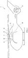
- FIG. 1 is a schematic diagram of a helicopter 1 according to an exemplary embodiment.
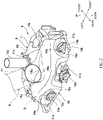
- FIG. 2 is a rear perspective view of a transmission cooling assembly 4 of FIG. 1 .
- the helicopter 1 includes a main rotor 2 and a tail rotor 3 which are connected to a transmission 8.
- the transmission cooling assembly 4 that cools the transmission 8 in a dry-run situation is disposed below the main rotor 2.
- a pair of left and right prime movers (such as turbines) 5 are disposed behind the main rotor 2.
- An oil cooler 6 and a fan 7 for oil cooler cooling are disposed in the vicinity of the transmission 8.
- the transmission cooling assembly 4 cools the transmission 8 with air. As shown in FIGS. 1 to 3 , the transmission cooling assembly 4 includes the transmission 8, a cowl 16, and a flow structure 9.
- the transmission 8 includes a speed change structure 10, a housing 11, seal retainers 14a and 14b, and seals 15.
- the speed change structure 10 changes the speed of rotation produced by rotational power input from at least one prime mover 5 of the helicopter and outputs the resulting rotational power.
- the speed change structure 10 of this exemplary embodiment changes the speed of rotation produced by rotational power input from the pair of prime movers 5 and outputs the resulting rotational power to the main rotor 2 and the tail rotor 3.
- the speed change structure 10 includes gears and rotating shafts. In normal situations, the gears and rotating shafts are lubricated with a lubricating oil supplied by a lubricating system of the helicopter 1.
- the speed change structure 10 includes input structures 10a and 10b to which the rotational power is input from the prime movers 5.
- the speed change structure 10 further includes output structures 10c and 10d from which the rotational power is output to the outside of the speed change structure 10.
- the output structure 10c outputs the rotational power to the main rotor 2.
- the output structure 10d outputs the rotational power to the tail rotor 3.
- Each of the input structures 10a and 10b and output structures 10c and 10d includes, for example, a hollow shaft rotatable about its axis.
- each of the input structures 10a and 10b includes: a hollow shaft 18 having gear teeth; a tubular structure 13a or 13b connected to an input shaft 12 described later; a free wheel clutch FW disposed between the hollow shaft 18 and the tubular structure 13a or 13b to transmit rotational power from the tubular structure 13a or 13b to the hollow shaft 18; and bearings B2 and B3 disposed between the hollow shaft 18 and the tubular structure 13a or 13b.
- the housing 11 accommodates the speed change structure 10.
- the housing 11 includes: at least one opening (a pair of openings 11a and 11b in this exemplary embodiment) through which the rotational power from the prime mover 5 is input to the speed change structure 10 accommodated in the housing 11; and at least one opening (a pair of openings 11c and 11d in this exemplary embodiment) through which the rotational power resulting from speed change by the speed change structure 10 is output to the outside of the housing 11.
- the input structure 10a is located inside the opening 11a
- the input structure 10b is located inside the opening 11b.
- a part of the output structure 10c protrudes out of the opening 11c.
- the output structure 10d is located inside the opening 11d.
- the opening 11d and the pair of openings 11a and 11b are located at the rear of the housing 11.
- the pair of openings 11a and 11b are spaced from each other in the left-right direction, and the opening 11d is located between the pair of openings 11a and 11b.
- the opening 11c is located at the top of the housing 11.
- the seal retainers 14a and 14b are attached to the openings 11a and 11b, respectively.
- the seal retainers 14a and 14b are fixed to the housing 11 by fasteners which are not shown.
- the seals 15 are disposed in contact with the input structures 10a and 10b, respectively. The seals 15 prevent the oil from leaking out of the housing 11 through the openings 11a and 11b.
- the helicopter 1 further includes the input shaft 12 through which the rotational power from the prime movers 5 is transmitted to the speed change structure 10.
- the prime movers 5 are connected to the input structures 10a and 10b of the speed change structure 10 by the input shaft 12.
- the transmission 8 includes at least one bearing supported by the housing 11 and rotatably supporting the input structure 10a or 10b.
- the transmission 8 includes several such bearings, examples of which are ball bearings B1 and B4 and a roller bearing B5 (see FIG. 3 ).
- the bearings B1, B4, and B5 of this exemplary embodiment support the input structure 10a or 10b at their inner rings and are directly or indirectly supported at their outer rings by the housing 11.
- the cowl 16 covers at least a part of the outer surface of the housing 11, with a gap G defined between the cowl 16 and the outer surface of the housing 11.
- the gap G extends along the outer surface of the housing 11.
- the gap G of this exemplary embodiment is not divided into separate portions.
- the gap G is continuous over the entire region between the outer surface of the housing 11 and the cowl 16.
- the cowl 16 is attached to the outer surface of the housing 11 with the aid of brackets which are not shown.
- the flow structure 9 allows external air to flow through the gap G along the outer surface of the housing 11.
- the cowl 16 is disposed to cover an area of the outer surface of the housing 11, the covered area being an area the cooling of which with external air is effective to ensure a long dry-run time.
- the covered area of the outer surface varies depending on the characteristics such as the components, configuration, and size of the transmission 8.
- that area of the outer surface of the housing 11 which is covered by the cowl 16 includes portions surrounding the peripheries of the input structures 10a and 10b.
- the cowl 16 includes introduction structures 16a through which external air is introduced into the gap G and a single discharge structure 16b through which the external air flowing through the gap G is discharged.
- the introduction structures 16a are located in both the left and right halves of the cowl 16 to introduce the external air into the gap G from the left and right ends and the upper and lower ends of the cowl 16.
- the discharge structure 16b is located at the top of the cowl 16 and at the center of the cowl 16 in the left-right direction to discharge the external air introduced into the gap G from both the left and right of the cowl 16.
- the discharge structure 16b is connected to the flow structure 9.
- the discharge structure 16b is in the shape of, for example, a cylindrical tube, but not limited to having this shape.
- the cowl 16 may include a single introduction structure 16a and two or more discharge structures 16b.
- the cowl 16 is a one-piece structure in this exemplary embodiment.
- the cowl 16 may be constructed by combining two or more components.
- the material of the cowl 16 can be selected as appropriate.
- the material of the cowl 16 is a resin in this exemplary embodiment, but may be another kind of material such as a metal.
- the flow structure 9 of this exemplary embodiment includes an air intake path connected to the discharge structure 16b of the cowl 16 and a fan that forces the external air to flow from the gap G into the air intake path.
- a main cooling target other than the transmission 8 is located in the direction of air delivery by the fan (outlet), and the discharge structure 16b of the cowl 16 is connected to the air intake path through which the external air is drawn towards the fan (inlet).
- the main cooling target is the oil cooler 6.
- the fan is the oil cooler-cooling fan 7 mounted in the helicopter 1, and the air intake path is an oil cooler-cooling air intake path 17 through which the air flows towards the fan 7.
- the fan of the flow structure 9 may deliver the air towards a main cooling target other than the oil cooler 6.
- the transmission cooling assembly 4 may include a flow structure 9 dedicated for allowing the external air to flow through the gap G, provided that conditions such as the weight and arrangement space of the transmission cooling assembly 4 are within permissible ranges.
- the input structures 10a and 10b are disposed in the flow paths of the external air flowing from the introduction structures 16a towards the discharge structure 16b through the gap G.
- Each of the input structures 10a and 10b is in the shape of a cylindrical tube and connected to the input shaft 12.
- the cowl 16 is disposed to surround the peripheries of the input structures 10a and 10b.
- the cowl 16 is disposed to allow the external air flowing through the gap G to cool the bearings B1, B4, and B5.
- the cowl 16 is shaped so as not to interfere with the opening 11d, and overlap between the cowl 16 and the opening 11d is avoided.
- the cowl 16 includes: a pair of openings 16c and 16d from each of which a part of a corresponding one of the pair of input structures 10a and 10b protrudes outside the cowl 16 when viewed from above; and a front wall 16e located at the front of the cowl 16 and between the openings 16c and 16d and extending in the up-down and left-right directions.
- the front wall 16e guides the external air flowing through the gap G towards the discharge structure 16b. Additionally, the front wall 16e prevents the external air from moving outside the cowl 16 from the front of the cowl 16 when flowing through the gap G.
- the pair of introduction structures 16a are spaced from each other in the left-right direction and associated respectively with the pair of input structures 10a and 10b.
- the transmission cooling assembly 4 cools the transmission 8 using external air. This eliminates the need to use, for example, a liquid coolant or a circulation structure for circulation of the coolant. As such, the transmission cooling assembly 4 with a relatively low weight can be constructed at low cost. Additionally, the size of the arrangement space for the transmission cooling assembly 4 in the helicopter 1 can be reduced.
- the cowl 16 may be in any shape that can cover the cooling target area of the housing 11.
- the cowl 16 may be shaped to be symmetrical or asymmetrical in either the left-right or up-down direction.
- the cowl 16 may be disposed to cover a wide area of the outer surface of the housing 11 to the extent that the cowl 16 does not interfere with any other component.
- FIG. 3 is a schematic cross-sectional view showing the bearings B1, B4, and B5 rotatably supporting the input structure 10a of the transmission cooling assembly 4 of FIG. 1 .
- FIG. 3 shows a vertical cross-section of the housing 11 and cowl 16 taken along a plane including the axes of the bearings B1, B4, and B5 disposed inside the opening 11a.
- the dimension of the gap G in a direction perpendicular to the outer surface of the housing 11 (this dimension may be referred to as "dimension D" hereinafter) is set large enough to allow the external air to flow through the gap G smoothly.
- the dimension D can be changed as appropriate, for example, to optimize the flow rate or flow velocity of the external air flowing through the gap G and maximize the heat transfer coefficient of the outer surface of the housing 11.
- the transmission cooling assembly 4 of this exemplary embodiment can cool the housing 11 efficiently using external air flowing through the gap G defined between the housing 11 and the cowl 16.
- seizure of the speed change structure 10 accommodated in the housing 11 can be reduced even in the dry-run situation.
- the components of the speed change structure 10 such as the bearings and gears mounted on the rotating shafts
- the transmission 8 can be prevented from suffering damages due to the transmission 8 being overheated as a result of seizure of the speed change structure 10.
- shortening of the possible flight time due to overheating of the transmission 8 can be prevented, and the possible flight time can be made longer than ever before.
- the lack of the lubricating oil in the dry-run situation could cause seizure of the toothed surfaces of the gears and hence an increased amount of heat generated in the transmission 8.
- the housing 11 can be cooled by the transmission cooling assembly 4 to reduce the increase in the amount of heat generated in the transmission 8 and thus make the dry-run time longer than ever before.
- the cowl 16 includes: the introduction structures 16a through which the external air is introduced into the gap G; and the discharge structure 16b through which the external air flowing through the gap G is discharged, and the flow structure 9 includes: the air intake path 17 connected to the discharge structure; and the fan 7 that forces the external air to flow from the gap G into the air intake path 17.
- the external air can be forced to flow through the gap G towards the air intake path 17 leading to the fan 7, and the cooling effect of the external air on the transmission 8 can be enhanced.
- the use of the air intake path 17 leading to the fan 7 can eliminate the need to dispose an additional structure for forcing the external air to flow through the gap G.
- the fan of the flow structure 9 is the fan 7 mounted in the helicopter 1 to cool the oil cooler.
- the use of the oil cooler-cooling fan 7 makes it possible, for example, to cool the oil cooler 6 by means of the fan 7 in normal situations and cool the transmission 8 by means of the fan 7 in the abnormal situation.
- the speed change structure 10 includes the input structures 10a and 10b to which the rotational power from the prime movers 5 is input, and the input structures 10a and 10b are disposed in the flow paths of the external air flowing from the introduction structures 16a towards the discharge structure 16b through the gap G.
- the input structures 10a and 10b which rotate at a relatively high speed and are likely to become hot, can be efficiently cooled using the external air flowing through the flow paths defined between the housing 11 and the cowl 16.
- the cowl 16 is disposed to surround the peripheries of the input structures 10a and 10b. This can further enhance the efficiency with which the input structures 10a and 10b are cooled by the external air flowing through the gap G.
- the prime movers 5 and the speed change structure 10 are connected by the input shaft 12 through which the rotational power from the prime movers 5 is transmitted to the input structures 10a and 10b of the speed change structure 10,
- the transmission 8 includes at least one bearing (bearings B1, B4, and B5 in this exemplary embodiment) supported by the housing 11 and rotatably supporting the input structure 10a or 10b, and the cowl 16 is disposed to allow the external air flowing through the gap G to cool the bearings B 1, B4, and B5.
- the bearings B2 and B 3 can also be efficiently cooled by the external air flowing through the gap G, and the transmission 8 can operate more smoothly.
- the input structures 10a and 10b of the speed change structure 10 include gears (e.g., bevel gears) to which rotational power is transmitted from the input shaft 12 as in this exemplary embodiment
- the bearings B1, B4, and B5 and the gears rotate at relatively high speeds and, for this reason, the helicopter 1 could be subjected to the harshest operation conditions in the dry-run situation.
- the transmission cooling assembly 4 can efficiently cool the bearings B1, B4, and B5 and the gears by the external air via the outer surface of the housing 11.
- overheating of the transmission 8 can be prevented to make the dry-run time longer than ever before.
- the transmission cooling assembly 4 may include two or more cowls 16. In this case, the cowls 16 of the transmission cooling assembly 4 may have different shapes.
- the discharge structure of the cowl 16 need not be connected to the air intake path.
- the transmission cooling assembly may include, for example, a flow structure by which external air flowing from the front to the rear of the helicopter 1 during flight of the helicopter 1 is supplied to the introduction structures 16a of the cowl 16.
- the flow structure in this case may include, for example, a duct.
- the front wall 16e of the cowl 16 may be disposed at a location other than between the pair of openings 16c and 16d.
Landscapes
- Engineering & Computer Science (AREA)
- Mechanical Engineering (AREA)
- Aviation & Aerospace Engineering (AREA)
- General Engineering & Computer Science (AREA)
- Chemical & Material Sciences (AREA)
- Combustion & Propulsion (AREA)
- General Details Of Gearings (AREA)
Abstract
Description
- The present disclosure relates to a transmission cooling assembly of a helicopter.
- For example, a transmission of a helicopter changes the speed of rotation produced by rotational power input from a prime mover and outputs the resulting rotational power. For the transmission to operate smoothly, it is common practice to supply a lubricating oil to the transmission by a lubricating system.
- PTL 1:
Japanese Laid-Open Patent Application Publication No. 2007-8461 - As disclosed in
Patent Literature 1, the transmission of the helicopter is required to have the ability to continue operating for a certain period of time even in an abnormal situation where the lubricating oil is not supplied to the transmission by the lubricating system during flight (this situation may be referred to as "dry-run situation" hereinafter). In such an abnormal situation, the lack of supply of the lubricating oil could cause severe overheating of the transmission, thus making it difficult for the transmission to operate smoothly. This leads to shortening of the possible flight time in the abnormal situation. - In order to solve the above problem, a transmission cooling assembly of a helicopter according to one aspect of the present disclosure includes: a transmission including a speed change structure that changes the speed of rotation produced by rotational power input from a prime mover and outputs the resulting rotational power and a housing accommodating the speed change structure; a cowl covering at least a part of an outer surface of the housing, with a gap defined between the cowl and the outer surface; and a flow structure that allows external air to flow through the gap.
- In the above configuration, the housing can be efficiently cooled using the external air flowing through the gap defined between the housing and the cowl. Thus, seizure of the speed change structure accommodated in the housing can be reduced even in the dry-run situation. As such, in the dry-run situation, shortening of the possible flight time due to overheating of the transmission can be prevented, and the possible flight time can be made longer than ever before.
- According to one aspect of the present disclosure, the possible flight time of a helicopter flying in an abnormal situation devoid of a lubricating oil supplied to a transmission by a lubricating system can be made longer than ever before.
-
-
FIG. 1 is a schematic diagram of a helicopter according to an exemplary embodiment. -
FIG. 2 is a rear perspective view of a transmission cooling assembly ofFIG. 1 . -
FIG. 3 is a schematic cross-sectional view showing bearings rotatably supporting an input structure of the transmission cooling assembly ofFIG. 1 . - Hereinafter, exemplary embodiments will be described with reference to the drawings.
FIG. 1 is a schematic diagram of ahelicopter 1 according to an exemplary embodiment.FIG. 2 is a rear perspective view of atransmission cooling assembly 4 ofFIG. 1 . - As shown in
FIG. 1 , thehelicopter 1 includes amain rotor 2 and atail rotor 3 which are connected to atransmission 8. Thetransmission cooling assembly 4 that cools thetransmission 8 in a dry-run situation is disposed below themain rotor 2. A pair of left and right prime movers (such as turbines) 5 are disposed behind themain rotor 2. Anoil cooler 6 and afan 7 for oil cooler cooling are disposed in the vicinity of thetransmission 8. - The
transmission cooling assembly 4 cools thetransmission 8 with air. As shown inFIGS. 1 to 3 , thetransmission cooling assembly 4 includes thetransmission 8, acowl 16, and aflow structure 9. Thetransmission 8 includes aspeed change structure 10, ahousing 11,seal retainers seals 15. - The
speed change structure 10 changes the speed of rotation produced by rotational power input from at least oneprime mover 5 of the helicopter and outputs the resulting rotational power. Thespeed change structure 10 of this exemplary embodiment changes the speed of rotation produced by rotational power input from the pair ofprime movers 5 and outputs the resulting rotational power to themain rotor 2 and thetail rotor 3. Thespeed change structure 10 includes gears and rotating shafts. In normal situations, the gears and rotating shafts are lubricated with a lubricating oil supplied by a lubricating system of thehelicopter 1. - The
speed change structure 10 includesinput structures prime movers 5. Thespeed change structure 10 further includesoutput structures speed change structure 10. Theoutput structure 10c outputs the rotational power to themain rotor 2. Theoutput structure 10d outputs the rotational power to thetail rotor 3. Each of theinput structures output structures input structures hollow shaft 18 having gear teeth; atubular structure input shaft 12 described later; a free wheel clutch FW disposed between thehollow shaft 18 and thetubular structure tubular structure hollow shaft 18; and bearings B2 and B3 disposed between thehollow shaft 18 and thetubular structure - The
housing 11 accommodates thespeed change structure 10. Thehousing 11 includes: at least one opening (a pair ofopenings prime mover 5 is input to thespeed change structure 10 accommodated in thehousing 11; and at least one opening (a pair ofopenings speed change structure 10 is output to the outside of thehousing 11. Theinput structure 10a is located inside the opening 11a, and theinput structure 10b is located inside the opening 11b. A part of theoutput structure 10c protrudes out of the opening 11c. Theoutput structure 10d is located inside the opening 11d. - For example, the opening 11d and the pair of
openings housing 11. The pair ofopenings openings housing 11. - The
seal retainers openings seal retainers housing 11 by fasteners which are not shown. Theseals 15 are disposed in contact with theinput structures seals 15 prevent the oil from leaking out of thehousing 11 through theopenings - As shown in
FIG. 1 , thehelicopter 1 further includes theinput shaft 12 through which the rotational power from theprime movers 5 is transmitted to thespeed change structure 10. In this exemplary embodiment, theprime movers 5 are connected to theinput structures speed change structure 10 by theinput shaft 12. Thetransmission 8 includes at least one bearing supported by thehousing 11 and rotatably supporting theinput structure transmission 8 includes several such bearings, examples of which are ball bearings B1 and B4 and a roller bearing B5 (seeFIG. 3 ). The bearings B1, B4, and B5 of this exemplary embodiment support theinput structure housing 11. - As shown in
FIG. 2 , thecowl 16 covers at least a part of the outer surface of thehousing 11, with a gap G defined between thecowl 16 and the outer surface of thehousing 11. The gap G extends along the outer surface of thehousing 11. For example, the gap G of this exemplary embodiment is not divided into separate portions. Thus, the gap G is continuous over the entire region between the outer surface of thehousing 11 and thecowl 16. Thecowl 16 is attached to the outer surface of thehousing 11 with the aid of brackets which are not shown. Theflow structure 9 allows external air to flow through the gap G along the outer surface of thehousing 11. - For example, the
cowl 16 is disposed to cover an area of the outer surface of thehousing 11, the covered area being an area the cooling of which with external air is effective to ensure a long dry-run time. The covered area of the outer surface varies depending on the characteristics such as the components, configuration, and size of thetransmission 8. In this exemplary embodiment, that area of the outer surface of thehousing 11 which is covered by thecowl 16 includes portions surrounding the peripheries of theinput structures - Specifically, the
cowl 16 includesintroduction structures 16a through which external air is introduced into the gap G and asingle discharge structure 16b through which the external air flowing through the gap G is discharged. Theintroduction structures 16a are located in both the left and right halves of thecowl 16 to introduce the external air into the gap G from the left and right ends and the upper and lower ends of thecowl 16. - The
discharge structure 16b is located at the top of thecowl 16 and at the center of thecowl 16 in the left-right direction to discharge the external air introduced into the gap G from both the left and right of thecowl 16. Thedischarge structure 16b is connected to theflow structure 9. Thedischarge structure 16b is in the shape of, for example, a cylindrical tube, but not limited to having this shape. Alternatively, thecowl 16 may include asingle introduction structure 16a and two ormore discharge structures 16b. - The
cowl 16 is a one-piece structure in this exemplary embodiment. Thecowl 16 may be constructed by combining two or more components. The material of thecowl 16 can be selected as appropriate. The material of thecowl 16 is a resin in this exemplary embodiment, but may be another kind of material such as a metal. - The
flow structure 9 of this exemplary embodiment includes an air intake path connected to thedischarge structure 16b of thecowl 16 and a fan that forces the external air to flow from the gap G into the air intake path. A main cooling target other than thetransmission 8 is located in the direction of air delivery by the fan (outlet), and thedischarge structure 16b of thecowl 16 is connected to the air intake path through which the external air is drawn towards the fan (inlet). In this exemplary embodiment, for example, the main cooling target is theoil cooler 6. - The fan is the oil cooler-cooling
fan 7 mounted in thehelicopter 1, and the air intake path is an oil cooler-coolingair intake path 17 through which the air flows towards thefan 7. The fan of theflow structure 9 may deliver the air towards a main cooling target other than theoil cooler 6. Thetransmission cooling assembly 4 may include aflow structure 9 dedicated for allowing the external air to flow through the gap G, provided that conditions such as the weight and arrangement space of thetransmission cooling assembly 4 are within permissible ranges. - In the
transmission cooling assembly 4 of this exemplary embodiment, theinput structures introduction structures 16a towards thedischarge structure 16b through the gap G. Each of theinput structures input shaft 12. Thecowl 16 is disposed to surround the peripheries of theinput structures transmission cooling assembly 4, thecowl 16 is disposed to allow the external air flowing through the gap G to cool the bearings B1, B4, and B5. Thecowl 16 is shaped so as not to interfere with theopening 11d, and overlap between thecowl 16 and theopening 11d is avoided. - In this exemplary embodiment, the
cowl 16 includes: a pair ofopenings input structures cowl 16 when viewed from above; and afront wall 16e located at the front of thecowl 16 and between theopenings front wall 16e guides the external air flowing through the gap G towards thedischarge structure 16b. Additionally, thefront wall 16e prevents the external air from moving outside thecowl 16 from the front of thecowl 16 when flowing through the gap G. In thecowl 16 of this exemplary embodiment, which includes thefront wall 16e, the pair ofintroduction structures 16a are spaced from each other in the left-right direction and associated respectively with the pair ofinput structures - As described above, the
transmission cooling assembly 4 cools thetransmission 8 using external air. This eliminates the need to use, for example, a liquid coolant or a circulation structure for circulation of the coolant. As such, thetransmission cooling assembly 4 with a relatively low weight can be constructed at low cost. Additionally, the size of the arrangement space for thetransmission cooling assembly 4 in thehelicopter 1 can be reduced. - The
cowl 16 may be in any shape that can cover the cooling target area of thehousing 11. Thus, for example, thecowl 16 may be shaped to be symmetrical or asymmetrical in either the left-right or up-down direction. Thecowl 16 may be disposed to cover a wide area of the outer surface of thehousing 11 to the extent that thecowl 16 does not interfere with any other component. -
FIG. 3 is a schematic cross-sectional view showing the bearings B1, B4, and B5 rotatably supporting theinput structure 10a of thetransmission cooling assembly 4 ofFIG. 1 . In particular,FIG. 3 shows a vertical cross-section of thehousing 11 andcowl 16 taken along a plane including the axes of the bearings B1, B4, and B5 disposed inside theopening 11a. As shown inFIG. 3 , the dimension of the gap G in a direction perpendicular to the outer surface of the housing 11 (this dimension may be referred to as "dimension D" hereinafter) is set large enough to allow the external air to flow through the gap G smoothly. The dimension D can be changed as appropriate, for example, to optimize the flow rate or flow velocity of the external air flowing through the gap G and maximize the heat transfer coefficient of the outer surface of thehousing 11. - As described above, the
transmission cooling assembly 4 of this exemplary embodiment can cool thehousing 11 efficiently using external air flowing through the gap G defined between thehousing 11 and thecowl 16. Thus, seizure of thespeed change structure 10 accommodated in thehousing 11 can be reduced even in the dry-run situation. As such, in the dry-run situation, the components of the speed change structure 10 (such as the bearings and gears mounted on the rotating shafts) can be prevented from suffering damages due to thetransmission 8 being overheated as a result of seizure of thespeed change structure 10. In the dry-run situation, therefore, shortening of the possible flight time due to overheating of thetransmission 8 can be prevented, and the possible flight time can be made longer than ever before. - Specifically, for example, the lack of the lubricating oil in the dry-run situation could cause seizure of the toothed surfaces of the gears and hence an increased amount of heat generated in the
transmission 8. Even in this case, thehousing 11 can be cooled by thetransmission cooling assembly 4 to reduce the increase in the amount of heat generated in thetransmission 8 and thus make the dry-run time longer than ever before. - The
cowl 16 includes: theintroduction structures 16a through which the external air is introduced into the gap G; and thedischarge structure 16b through which the external air flowing through the gap G is discharged, and theflow structure 9 includes: theair intake path 17 connected to the discharge structure; and thefan 7 that forces the external air to flow from the gap G into theair intake path 17. In this configuration, the external air can be forced to flow through the gap G towards theair intake path 17 leading to thefan 7, and the cooling effect of the external air on thetransmission 8 can be enhanced. Additionally, the use of theair intake path 17 leading to thefan 7 can eliminate the need to dispose an additional structure for forcing the external air to flow through the gap G. - In this exemplary embodiment, the fan of the
flow structure 9 is thefan 7 mounted in thehelicopter 1 to cool the oil cooler. The use of the oil cooler-coolingfan 7 makes it possible, for example, to cool theoil cooler 6 by means of thefan 7 in normal situations and cool thetransmission 8 by means of thefan 7 in the abnormal situation. - The
speed change structure 10 includes theinput structures prime movers 5 is input, and theinput structures introduction structures 16a towards thedischarge structure 16b through the gap G. Thus, theinput structures housing 11 and thecowl 16. - The
cowl 16 is disposed to surround the peripheries of theinput structures input structures - The
prime movers 5 and thespeed change structure 10 are connected by theinput shaft 12 through which the rotational power from theprime movers 5 is transmitted to theinput structures speed change structure 10, thetransmission 8 includes at least one bearing (bearings B1, B4, and B5 in this exemplary embodiment) supported by thehousing 11 and rotatably supporting theinput structure cowl 16 is disposed to allow the external air flowing through the gap G to cool thebearings B 1, B4, and B5. Thus, overheating of the bearings B1, B4, and B5 can be reduced to enable thetransmission 8 to operate smoothly even in the case where, for example, theinput shaft 12 rotates at a relatively high speed. Additionally, in this exemplary embodiment, the bearings B2 andB 3 can also be efficiently cooled by the external air flowing through the gap G, and thetransmission 8 can operate more smoothly. - For example, in the case where the
input structures speed change structure 10 include gears (e.g., bevel gears) to which rotational power is transmitted from theinput shaft 12 as in this exemplary embodiment, the bearings B1, B4, and B5 and the gears rotate at relatively high speeds and, for this reason, thehelicopter 1 could be subjected to the harshest operation conditions in the dry-run situation. Even in such a case, thetransmission cooling assembly 4 can efficiently cool the bearings B1, B4, and B5 and the gears by the external air via the outer surface of thehousing 11. Thus, overheating of thetransmission 8 can be prevented to make the dry-run time longer than ever before. - The present disclosure is not limited to the embodiment described above, and changes, additions, or deletions may be made without departing from the gist of the present disclosure. The
transmission cooling assembly 4 may include two or more cowls 16. In this case, thecowls 16 of thetransmission cooling assembly 4 may have different shapes. - The discharge structure of the
cowl 16 need not be connected to the air intake path. In the case where the discharge structure is not connected to the air intake path, the transmission cooling assembly may include, for example, a flow structure by which external air flowing from the front to the rear of thehelicopter 1 during flight of thehelicopter 1 is supplied to theintroduction structures 16a of thecowl 16. The flow structure in this case may include, for example, a duct. Thefront wall 16e of thecowl 16 may be disposed at a location other than between the pair ofopenings -
-
B 1, B4, B5 - bearing
- G
- gap
- 1
- helicopter
- 4
- transmission cooling assembly
- 5
- prime mover
- 6
- oil cooler
- 7
- oil cooler-cooling fan
- 8
- transmission
- 9
- flow structure
- 10
- speed change structure
- 10a, 10b
- input structure
- 11
- housing
- 12
- input shaft
- 16
- cowl
- 16a
- introduction structure
- 16b
- discharge structure
- 17
- air intake path
Claims (6)
- A transmission cooling assembly of a helicopter, the transmission cooling assembly comprising:a transmission including a speed change structure that changes the speed of rotation produced by rotational power input from a prime mover and outputs the resulting rotational power and a housing accommodating the speed change structure;a cowl covering at least a part of an outer surface of the housing, with a gap defined between the cowl and the outer surface; anda flow structure that allows external air to flow through the gap.
- The transmission cooling assembly according to claim 1, whereinthe cowl includes:an introduction structure through which the external air is introduced into the gap; anda discharge structure through which the external air flowing through the gap is discharged, andthe flow structure includes:an air intake path connected to the discharge structure; anda fan that forces the external air to flow from the gap into the air intake path.
- The transmission cooling assembly according to claim 2, wherein the fan is a fan mounted in the helicopter to cool an oil cooler.
- The transmission cooling assembly according to claim 2 or 3, whereinthe speed change structure includes an input structure to which the rotational power from the prime mover is input, andthe input structure is disposed in a flow path of the external air flowing from the introduction structure towards the discharge structure through the gap.
- The transmission cooling assembly according to claim 4, wherein the cowl is disposed to surround a periphery of the input structure.
- The transmission cooling assembly according to any one of claims 1 to 5, whereinthe prime mover and the speed change structure are connected by an input shaft through which the rotational power from the prime mover is transmitted to the speed change structure,the transmission includes at least one bearing supported by the housing and rotatably supporting the input shaft, andthe cowl is disposed to allow the external air flowing through the gap to cool the bearing.
Applications Claiming Priority (2)
| Application Number | Priority Date | Filing Date | Title |
|---|---|---|---|
| JP2019236611A JP7333267B2 (en) | 2019-12-26 | 2019-12-26 | helicopter |
| PCT/JP2020/047287 WO2021132038A1 (en) | 2019-12-26 | 2020-12-17 | Helicopter transmission cooling structure |
Publications (2)
| Publication Number | Publication Date |
|---|---|
| EP4082904A1 true EP4082904A1 (en) | 2022-11-02 |
| EP4082904A4 EP4082904A4 (en) | 2023-12-06 |
Family
ID=76574605
Family Applications (1)
| Application Number | Title | Priority Date | Filing Date |
|---|---|---|---|
| EP20906335.3A Pending EP4082904A4 (en) | 2019-12-26 | 2020-12-17 | Helicopter transmission cooling structure |
Country Status (4)
| Country | Link |
|---|---|
| US (1) | US12043401B2 (en) |
| EP (1) | EP4082904A4 (en) |
| JP (1) | JP7333267B2 (en) |
| WO (1) | WO2021132038A1 (en) |
Families Citing this family (2)
| Publication number | Priority date | Publication date | Assignee | Title |
|---|---|---|---|---|
| JP7421331B2 (en) * | 2019-12-26 | 2024-01-24 | 川崎重工業株式会社 | helicopter transmission structure |
| CN121205784B (en) * | 2025-09-09 | 2026-06-30 | 贵州永红航空机械有限责任公司 | Lubricating oil heat dissipation device and heat dissipation method for helicopter |
Family Cites Families (7)
| Publication number | Priority date | Publication date | Assignee | Title |
|---|---|---|---|---|
| FR2683204B1 (en) * | 1991-10-30 | 1997-04-25 | Aerospatiale | SYSTEM FOR BACKING UP A MULTIPLIER / REDUCER MECHANICAL ASSEMBLY, PARTICULARLY OF THE HELICOPTER "TRANSMISSION" TYPE, IN CASE OF LOSS OF LUBRICATING OIL. |
| JP4284110B2 (en) * | 2003-05-26 | 2009-06-24 | 富士重工業株式会社 | Helicopter |
| ATE390349T1 (en) | 2005-06-30 | 2008-04-15 | Agusta Spa | HELICOPTER WITH AUXILIARY LUBRICANT OIL CIRCUIT |
| PL2133265T3 (en) * | 2008-06-10 | 2011-01-31 | Agusta Spa | Helicopter |
| EP2712805B1 (en) * | 2012-09-28 | 2016-03-02 | AGUSTAWESTLAND S.p.A. | System and method for cooling a hover-capable aircraft transmission |
| US8985517B2 (en) * | 2012-10-26 | 2015-03-24 | Textron Innovations Inc. | Passive cooling of transmission using mast mounted heat pipes |
| US10344846B2 (en) * | 2016-09-23 | 2019-07-09 | Bell Helicopter Textron Inc. | Fan mounted on gearshaft |
-
2019
- 2019-12-26 JP JP2019236611A patent/JP7333267B2/en active Active
-
2020
- 2020-12-17 EP EP20906335.3A patent/EP4082904A4/en active Pending
- 2020-12-17 WO PCT/JP2020/047287 patent/WO2021132038A1/en not_active Ceased
-
2022
- 2022-06-24 US US17/849,241 patent/US12043401B2/en active Active
Also Published As
| Publication number | Publication date |
|---|---|
| US12043401B2 (en) | 2024-07-23 |
| JP7333267B2 (en) | 2023-08-24 |
| EP4082904A4 (en) | 2023-12-06 |
| US20220324581A1 (en) | 2022-10-13 |
| WO2021132038A1 (en) | 2021-07-01 |
| JP2021104730A (en) | 2021-07-26 |
Similar Documents
| Publication | Publication Date | Title |
|---|---|---|
| US7579725B2 (en) | Liquid cooled rotor assembly | |
| US12043401B2 (en) | Transmission cooling assembly of helicopter | |
| JP5714405B2 (en) | Gas turbine engine | |
| US10418882B2 (en) | Traction motor with cooling fan for improved cooling flow | |
| CN115004524A (en) | System for cooling a propeller drive having a plurality of electric motors | |
| JPH0989064A (en) | Friction continuously variable transmission | |
| CN111431324A (en) | Water-cooled motor | |
| US20190323510A1 (en) | Turbocharger with a shaft comprising a free portion | |
| US10734865B2 (en) | Electric motor having improved cooling | |
| JP7712992B2 (en) | Arrangement and vehicle with electric machine and gearbox - Patent application | |
| US20110236193A1 (en) | Turbocharger bearing lubrication | |
| KR20100089832A (en) | Ship propulsion system having a pump jet | |
| CZ289138B6 (en) | Motor assembly and a geared-down motor unit | |
| BR102014021617A2 (en) | floating bearing motor pump cooled by a circulating fluid | |
| US2804280A (en) | Turbine bearing lubrication system | |
| US3179328A (en) | Turbo-compressors | |
| KR200479994Y1 (en) | Cooling arrangement for an axial fan | |
| CN114901923B (en) | Pressurization of a lubrication chamber in a turbomachine with a counter-rotating turbine | |
| US12580444B2 (en) | Component | |
| WO2021039927A1 (en) | Gas turbine engine | |
| US20220242543A1 (en) | Pod propulsion device | |
| WO2019182933A1 (en) | A system to provide reliable flow of low temperature cooling air to an antifriction bearing buried inside a rotating machine | |
| US20250207510A1 (en) | Lubrication and cooling of equipment of an aircraft turbomachine | |
| KR102946765B1 (en) | Apparatus and method for cooling | |
| US12323025B2 (en) | Heat exchanger system for an electric motor with fluid circuits arranged between shafts |
Legal Events
| Date | Code | Title | Description |
|---|---|---|---|
| STAA | Information on the status of an ep patent application or granted ep patent |
Free format text: STATUS: THE INTERNATIONAL PUBLICATION HAS BEEN MADE |
|
| PUAI | Public reference made under article 153(3) epc to a published international application that has entered the european phase |
Free format text: ORIGINAL CODE: 0009012 |
|
| STAA | Information on the status of an ep patent application or granted ep patent |
Free format text: STATUS: REQUEST FOR EXAMINATION WAS MADE |
|
| 17P | Request for examination filed |
Effective date: 20220707 |
|
| AK | Designated contracting states |
Kind code of ref document: A1 Designated state(s): AL AT BE BG CH CY CZ DE DK EE ES FI FR GB GR HR HU IE IS IT LI LT LU LV MC MK MT NL NO PL PT RO RS SE SI SK SM TR |
|
| DAV | Request for validation of the european patent (deleted) | ||
| DAX | Request for extension of the european patent (deleted) | ||
| REG | Reference to a national code |
Ref country code: DE Ref legal event code: R079 Free format text: PREVIOUS MAIN CLASS: B64C0027140000 Ipc: B64C0027120000 |
|
| A4 | Supplementary search report drawn up and despatched |
Effective date: 20231106 |
|
| RIC1 | Information provided on ipc code assigned before grant |
Ipc: F16C 19/00 20060101ALI20231030BHEP Ipc: B64D 35/00 20060101ALI20231030BHEP Ipc: B64D 33/08 20060101ALI20231030BHEP Ipc: B64C 27/12 20060101AFI20231030BHEP |
|
| STAA | Information on the status of an ep patent application or granted ep patent |
Free format text: STATUS: EXAMINATION IS IN PROGRESS |
|
| 17Q | First examination report despatched |
Effective date: 20250402 |