EP4082854B1 - Vehicle velocity control method and device - Google Patents
Vehicle velocity control method and device Download PDFInfo
- Publication number
- EP4082854B1 EP4082854B1 EP22165337.1A EP22165337A EP4082854B1 EP 4082854 B1 EP4082854 B1 EP 4082854B1 EP 22165337 A EP22165337 A EP 22165337A EP 4082854 B1 EP4082854 B1 EP 4082854B1
- Authority
- EP
- European Patent Office
- Prior art keywords
- drivable
- current vehicle
- distances
- velocity
- area
- Prior art date
- Legal status (The legal status is an assumption and is not a legal conclusion. Google has not performed a legal analysis and makes no representation as to the accuracy of the status listed.)
- Active
Links
Images


Classifications
-
- B—PERFORMING OPERATIONS; TRANSPORTING
- B60—VEHICLES IN GENERAL
- B60W—CONJOINT CONTROL OF VEHICLE SUB-UNITS OF DIFFERENT TYPE OR DIFFERENT FUNCTION; CONTROL SYSTEMS SPECIALLY ADAPTED FOR HYBRID VEHICLES; ROAD VEHICLE DRIVE CONTROL SYSTEMS FOR PURPOSES NOT RELATED TO THE CONTROL OF A PARTICULAR SUB-UNIT
- B60W30/00—Purposes of road vehicle drive control systems not related to the control of a particular sub-unit, e.g. of systems using conjoint control of vehicle sub-units
- B60W30/14—Adaptive cruise control
- B60W30/143—Speed control
-
- B—PERFORMING OPERATIONS; TRANSPORTING
- B60—VEHICLES IN GENERAL
- B60W—CONJOINT CONTROL OF VEHICLE SUB-UNITS OF DIFFERENT TYPE OR DIFFERENT FUNCTION; CONTROL SYSTEMS SPECIALLY ADAPTED FOR HYBRID VEHICLES; ROAD VEHICLE DRIVE CONTROL SYSTEMS FOR PURPOSES NOT RELATED TO THE CONTROL OF A PARTICULAR SUB-UNIT
- B60W30/00—Purposes of road vehicle drive control systems not related to the control of a particular sub-unit, e.g. of systems using conjoint control of vehicle sub-units
- B60W30/14—Adaptive cruise control
- B60W30/16—Control of distance between vehicles, e.g. keeping a distance to preceding vehicle
-
- B—PERFORMING OPERATIONS; TRANSPORTING
- B60—VEHICLES IN GENERAL
- B60W—CONJOINT CONTROL OF VEHICLE SUB-UNITS OF DIFFERENT TYPE OR DIFFERENT FUNCTION; CONTROL SYSTEMS SPECIALLY ADAPTED FOR HYBRID VEHICLES; ROAD VEHICLE DRIVE CONTROL SYSTEMS FOR PURPOSES NOT RELATED TO THE CONTROL OF A PARTICULAR SUB-UNIT
- B60W40/00—Estimation or calculation of non-directly measurable driving parameters for road vehicle drive control systems not related to the control of a particular sub unit, e.g. by using mathematical models
- B60W40/02—Estimation or calculation of non-directly measurable driving parameters for road vehicle drive control systems not related to the control of a particular sub unit, e.g. by using mathematical models related to ambient conditions
- B60W40/04—Traffic conditions
-
- B—PERFORMING OPERATIONS; TRANSPORTING
- B60—VEHICLES IN GENERAL
- B60W—CONJOINT CONTROL OF VEHICLE SUB-UNITS OF DIFFERENT TYPE OR DIFFERENT FUNCTION; CONTROL SYSTEMS SPECIALLY ADAPTED FOR HYBRID VEHICLES; ROAD VEHICLE DRIVE CONTROL SYSTEMS FOR PURPOSES NOT RELATED TO THE CONTROL OF A PARTICULAR SUB-UNIT
- B60W50/00—Details of control systems for road vehicle drive control not related to the control of a particular sub-unit, e.g. process diagnostic or vehicle driver interfaces
-
- B—PERFORMING OPERATIONS; TRANSPORTING
- B60—VEHICLES IN GENERAL
- B60K—ARRANGEMENT OR MOUNTING OF PROPULSION UNITS OR OF TRANSMISSIONS IN VEHICLES; ARRANGEMENT OR MOUNTING OF PLURAL DIVERSE PRIME-MOVERS IN VEHICLES; AUXILIARY DRIVES FOR VEHICLES; INSTRUMENTATION OR DASHBOARDS FOR VEHICLES; ARRANGEMENTS IN CONNECTION WITH COOLING, AIR INTAKE, GAS EXHAUST OR FUEL SUPPLY OF PROPULSION UNITS IN VEHICLES
- B60K31/00—Vehicle fittings, acting on a single sub-unit only, for automatically controlling vehicle speed, i.e. preventing speed from exceeding an arbitrarily established velocity or maintaining speed at a particular velocity, as selected by the vehicle operator
- B60K31/0008—Vehicle fittings, acting on a single sub-unit only, for automatically controlling vehicle speed, i.e. preventing speed from exceeding an arbitrarily established velocity or maintaining speed at a particular velocity, as selected by the vehicle operator including means for detecting potential obstacles in vehicle path
- B60K2031/005—Selecting more than one target vehicle, e.g. using several preceding vehicles as target
-
- B—PERFORMING OPERATIONS; TRANSPORTING
- B60—VEHICLES IN GENERAL
- B60W—CONJOINT CONTROL OF VEHICLE SUB-UNITS OF DIFFERENT TYPE OR DIFFERENT FUNCTION; CONTROL SYSTEMS SPECIALLY ADAPTED FOR HYBRID VEHICLES; ROAD VEHICLE DRIVE CONTROL SYSTEMS FOR PURPOSES NOT RELATED TO THE CONTROL OF A PARTICULAR SUB-UNIT
- B60W2420/00—Indexing codes relating to the type of sensors based on the principle of their operation
- B60W2420/40—Photo, light or radio wave sensitive means, e.g. infrared sensors
- B60W2420/403—Image sensing, e.g. optical camera
-
- B—PERFORMING OPERATIONS; TRANSPORTING
- B60—VEHICLES IN GENERAL
- B60W—CONJOINT CONTROL OF VEHICLE SUB-UNITS OF DIFFERENT TYPE OR DIFFERENT FUNCTION; CONTROL SYSTEMS SPECIALLY ADAPTED FOR HYBRID VEHICLES; ROAD VEHICLE DRIVE CONTROL SYSTEMS FOR PURPOSES NOT RELATED TO THE CONTROL OF A PARTICULAR SUB-UNIT
- B60W2420/00—Indexing codes relating to the type of sensors based on the principle of their operation
- B60W2420/40—Photo, light or radio wave sensitive means, e.g. infrared sensors
- B60W2420/408—Radar; Laser, e.g. lidar
-
- B—PERFORMING OPERATIONS; TRANSPORTING
- B60—VEHICLES IN GENERAL
- B60W—CONJOINT CONTROL OF VEHICLE SUB-UNITS OF DIFFERENT TYPE OR DIFFERENT FUNCTION; CONTROL SYSTEMS SPECIALLY ADAPTED FOR HYBRID VEHICLES; ROAD VEHICLE DRIVE CONTROL SYSTEMS FOR PURPOSES NOT RELATED TO THE CONTROL OF A PARTICULAR SUB-UNIT
- B60W2520/00—Input parameters relating to overall vehicle dynamics
- B60W2520/10—Longitudinal speed
-
- B—PERFORMING OPERATIONS; TRANSPORTING
- B60—VEHICLES IN GENERAL
- B60W—CONJOINT CONTROL OF VEHICLE SUB-UNITS OF DIFFERENT TYPE OR DIFFERENT FUNCTION; CONTROL SYSTEMS SPECIALLY ADAPTED FOR HYBRID VEHICLES; ROAD VEHICLE DRIVE CONTROL SYSTEMS FOR PURPOSES NOT RELATED TO THE CONTROL OF A PARTICULAR SUB-UNIT
- B60W2552/00—Input parameters relating to infrastructure
- B60W2552/50—Barriers
-
- B—PERFORMING OPERATIONS; TRANSPORTING
- B60—VEHICLES IN GENERAL
- B60W—CONJOINT CONTROL OF VEHICLE SUB-UNITS OF DIFFERENT TYPE OR DIFFERENT FUNCTION; CONTROL SYSTEMS SPECIALLY ADAPTED FOR HYBRID VEHICLES; ROAD VEHICLE DRIVE CONTROL SYSTEMS FOR PURPOSES NOT RELATED TO THE CONTROL OF A PARTICULAR SUB-UNIT
- B60W2554/00—Input parameters relating to objects
- B60W2554/40—Dynamic objects, e.g. animals, windblown objects
- B60W2554/402—Type
-
- B—PERFORMING OPERATIONS; TRANSPORTING
- B60—VEHICLES IN GENERAL
- B60W—CONJOINT CONTROL OF VEHICLE SUB-UNITS OF DIFFERENT TYPE OR DIFFERENT FUNCTION; CONTROL SYSTEMS SPECIALLY ADAPTED FOR HYBRID VEHICLES; ROAD VEHICLE DRIVE CONTROL SYSTEMS FOR PURPOSES NOT RELATED TO THE CONTROL OF A PARTICULAR SUB-UNIT
- B60W2554/00—Input parameters relating to objects
- B60W2554/40—Dynamic objects, e.g. animals, windblown objects
- B60W2554/404—Characteristics
- B60W2554/4042—Longitudinal speed
-
- B—PERFORMING OPERATIONS; TRANSPORTING
- B60—VEHICLES IN GENERAL
- B60W—CONJOINT CONTROL OF VEHICLE SUB-UNITS OF DIFFERENT TYPE OR DIFFERENT FUNCTION; CONTROL SYSTEMS SPECIALLY ADAPTED FOR HYBRID VEHICLES; ROAD VEHICLE DRIVE CONTROL SYSTEMS FOR PURPOSES NOT RELATED TO THE CONTROL OF A PARTICULAR SUB-UNIT
- B60W2554/00—Input parameters relating to objects
- B60W2554/80—Spatial relation or speed relative to objects
- B60W2554/801—Lateral distance
-
- B—PERFORMING OPERATIONS; TRANSPORTING
- B60—VEHICLES IN GENERAL
- B60W—CONJOINT CONTROL OF VEHICLE SUB-UNITS OF DIFFERENT TYPE OR DIFFERENT FUNCTION; CONTROL SYSTEMS SPECIALLY ADAPTED FOR HYBRID VEHICLES; ROAD VEHICLE DRIVE CONTROL SYSTEMS FOR PURPOSES NOT RELATED TO THE CONTROL OF A PARTICULAR SUB-UNIT
- B60W2554/00—Input parameters relating to objects
- B60W2554/80—Spatial relation or speed relative to objects
- B60W2554/802—Longitudinal distance
-
- B—PERFORMING OPERATIONS; TRANSPORTING
- B60—VEHICLES IN GENERAL
- B60W—CONJOINT CONTROL OF VEHICLE SUB-UNITS OF DIFFERENT TYPE OR DIFFERENT FUNCTION; CONTROL SYSTEMS SPECIALLY ADAPTED FOR HYBRID VEHICLES; ROAD VEHICLE DRIVE CONTROL SYSTEMS FOR PURPOSES NOT RELATED TO THE CONTROL OF A PARTICULAR SUB-UNIT
- B60W2720/00—Output or target parameters relating to overall vehicle dynamics
- B60W2720/10—Longitudinal speed
Definitions
- the invention relates to the field of vehicle control, and in particular, to a vehicle velocity control method and device, a computer storage medium, and a vehicle.
- an existing function of vehicle adaptive cruise control mainly takes into consideration the target ahead on a traveling route of the present vehicle, and controls a velocity of the present vehicle while ensuring a safe distance between the present vehicle and a vehicle ahead.
- the control logic may neglect the vehicles at the two sides that have entered a surrounding space, which intensifies a feeling of insecurity of a driver during driving and results in a declined trust in the function.
- objects on a road that can "surround" the present vehicle are not limited to other vehicles, and also include static road structures such as road median strips and curbs. These targets together affect the determination of the driver as to whether a current driving environment is safe.
- US2006/0217866A1 relates to a method for controlling the speed of a vehicle, wherein a future traffic situation is predicted as a function of the acceleration of the controlled vehicle.
- the future traffic situation is then evaluated with a cost function which is defined in such a way that its value increases with the number and relevance of the other vehicles which are traveling in front and are relevant to the controlled vehicle.
- the value of the acceleration which minimizes the cost function is then determined as an acceleration setpoint value, and the acceleration of the vehicle is adjusted to this value.
- a vehicle velocity control method including: determining, by an onboard sensor, drivable distances in different directions in front of a current vehicle, and obtaining, at least based on types of targets in the different directions, an area of a drivable space in front of the current vehicle; determining, based on the area of the drivable space and a current vehicle velocity, a result of a safety degree in a current driving scenario; and controlling the vehicle velocity of the current vehicle based on the result of the safety degree.
- the determining, by an onboard sensor, drivable distances in different directions in front of a current vehicle, and obtaining, at least based on types of targets in the different directions, an area of a drivable space in front of the current vehicle include: determining, by the onboard sensor, the drivable distances in the different directions in front of the current vehicle; correcting the drivable distances at least based on the types of the targets in the different directions, to obtain a corrected drivable distance in each direction; and calculating, based on the corrected drivable distance in each direction, the area of the drivable space in front of the current vehicle.
- the correcting the drivable distances at least based on the types of the targets in the different directions, to obtain a corrected drivable distance in each direction includes: correcting the drivable distances of the vehicle based on a safe driving area, where the correction takes into consideration psychological feelings of a driver and a distance relative to a lane-changing vehicle.
- the determining, based on the area of the drivable space and a current vehicle velocity, a result of a safety degree in a current driving scenario includes: comparing the area of the drivable space with area thresholds of drivable spaces of different safety levels that correspond to the current vehicle velocity, to determine the result of the safety degree in the current driving scenario.
- the controlling the vehicle velocity of the current vehicle based on the result of the safety degree includes: outputting a recommended velocity for current vehicle driving based on the result of the safety degree and in combination with the current vehicle velocity.
- a recommended velocity lower than the current vehicle velocity is output when the result of the safety degree indicates a lower driving safety.
- a vehicle velocity control device including: a first determination apparatus configured to: determine, by an onboard sensor, drivable distances in different directions in front of a current vehicle, and obtain, at least based on types of targets in the different directions, an area of a drivable space in front of the current vehicle; a second determination apparatus configured to determine, based on the area of the drivable space and a current vehicle velocity, a result of a safety degree in a current driving scenario; and a control apparatus configured to control the vehicle velocity of the current vehicle based on the result of the safety degree.
- the first determination apparatus includes: a determination unit configured to determine, by the onboard sensor, the drivable distances in the different directions in front of the current vehicle; a correction unit configured to correct the drivable distances at least based on the types of the targets in the different directions, to obtain a corrected drivable distance in each direction; and a calculation unit configured to calculate, based on the corrected drivable distance in each direction, the area of the drivable space in front of the current vehicle.
- the correction unit is configured to correct the drivable distances of the vehicle based on a safe driving area, where the correction takes into consideration psychological feelings of a driver and a distance relative to a lane-changing vehicle.
- the second determination apparatus is configured to: compare the area of the drivable space with area thresholds of drivable spaces of different safety levels that correspond to the current vehicle velocity, to determine the result of the safety degree in the current driving scenario.
- control apparatus is configured to: output a recommended velocity for current vehicle driving based on the result of the safety degree and in combination with the current vehicle velocity.
- control apparatus is configured to output a recommended velocity lower than the current vehicle velocity when the result of the safety degree indicates a lower driving safety.
- a computer storage medium including instructions, where when the instructions are run, the method as described above is performed.
- a vehicle including the device as described above.
- the area of the drivable space in front of the present vehicle is determined, the result of the safety degree of a current vehicle driving environment is assessed, and a recommendation and control are made to the present vehicle in terms of velocity based on an assessment result, such that the present vehicle will not drive into or will take the initiative to drive away from a narrow driving area after adjustments made in advance based on a recommended velocity, thereby strengthening the security of a driver during driving and ameliorating the problem that a vehicle enters a narrow driving space in a multi-vehicle scenario.
- control logic of the invention may be included on a computer-readable medium as executable program instructions, which are implemented by a processor or the like.
- the computer-readable medium include, but are not limited to, a ROM, a RAM, an optical disc, a magnetic tape, a floppy disk, a flash drive, a smart card, and an optical data storage apparatus.
- a computer-readable recording medium may also be distributed in a computer system connected to a network, so that the computer-readable medium is stored and implemented in a distributed manner, for example, through a vehicle telematics service or a controller area network (CAN).
- CAN controller area network
- vehicle or other similar terms used herein includes general motor vehicles, such as passenger vehicles (including sport utility vehicles, buses, trucks, etc.) and various commercial vehicles, and includes hybrid vehicles, electric vehicles, etc.
- a hybrid vehicle is a vehicle with two or more power sources, such as a vehicle powered by a gasoline engine and an electric motor.
- FIG. 1 is a schematic flowchart of a vehicle velocity control method 1000 according to an embodiment of the invention. As shown in FIG. 1 , the vehicle velocity control method 1000 includes the following steps:
- onboard sensor also referred to as automobile sensor or a vehicle sensor
- vehicle sensor is an important component device for smart driving, which is the key to perception of an external environment by a vehicle.
- the onboard sensor may be a camera, a millimeter wave radar, or a laser radar.
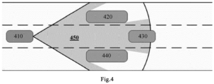
- FIG. 4 is a schematic diagram of a drivable space of a vehicle according to an embodiment of the invention. As shown in FIG.
- a present vehicle is shown as 410, and other vehicles 420, 430, and 440 move ahead of the present vehicle 410, where the vehicle 420 travels in a lane on the left of the present vehicle 410, the vehicle 430 and the present vehicle 410 travel in a same plane, and the vehicle 440 travels in a lane on the right of the present vehicle 410.
- a drivable space within a recognition range of the sensor of the present vehicle (“drivable space" for short) is shown at 450.
- An area of the space 450 that is, an area of a gray space denoted by 450 is the area of the drivable space.
- Type of target refers to a type of a target object in front of the present vehicle (sensor).
- the target object may be other vehicles, or may be static road structures such as a median strip or a curb. Therefore, in one or more embodiments of the invention, the area of the drivable space in front of the current vehicle may be obtained in different manners depending on different types of target objects in different directions.
- the term "result of safety degree in current driving scenario” refers to an assessment result for a safety degree of a driving environment of the current vehicle as far as a driver is concerned, such that a recommendation or control may be made to the present vehicle in terms of velocity based on the assessment result. In this way, a declined trust of the driver in functions caused due to the vehicle entering a narrow driving space is prevented.
- the vehicle velocity control method 1000 is a method in which the area of the drivable space in front of the present vehicle is calculated, a safety degree of a current driving environment as far as a driver is concerned is assessed, and a recommended current traveling velocity of the present vehicle is provided based on an assessment result, such that an increased psychological burden on the driver caused due to the vehicle driving into a narrow driving space in some scenarios is prevented.
- step S 110 includes: determining, by the onboard sensor, the drivable distances in the different directions in front of the current vehicle; correcting the drivable distances at least based on the types of the targets in the different directions, to obtain a corrected drivable distance in each direction; and calculating, based on the corrected drivable distance in each direction, the area of the drivable space in front of the current vehicle.
- the correcting the drivable distances at least based on the types of the targets in the different directions, to obtain a corrected drivable distance in each direction includes: when the drivable distance is less than the safe driving distance corresponding to the current vehicle velocity and a target in the direction is a static road structure, such as a median strip or a curb, instead of another vehicle, since a road structure causes a much lower sense of insecurity to the driver than a vehicle, correcting a driving distance to a safe driving distance in a certain proportion, where a correction proportion k is an empirical value.
- the correcting the drivable distances at least based on the types of the targets in the different directions, to obtain a corrected drivable distance in each direction includes: when the drivable distance is less than the safe driving distance corresponding to the current vehicle velocity and a target in the direction is another vehicle with a velocity much higher than a traveling velocity of the present vehicle at a current moment (that is, the current vehicle velocity), since it is believed that the target vehicle will be far away from the present vehicle soon and the scenario will come back into a safe range soon, correcting a driving distance to a safe driving distance in a certain proportion, where a correction proportion k is an empirical value.
- a corrected result for a drivable distance in another direction may be used instead to calculate an approximation of an area of triangle, and in this case, ⁇ ⁇ i is correspondingly modified to an angle difference in the corresponding directions.
- step S 120 includes: comparing the area of the drivable space with area thresholds A thres of drivable spaces of different safety levels that correspond to the current vehicle velocity, to determine the result of the safety degree in the current driving scenario.
- the "area thresholds A thres of drivable spaces of different safety levels" and the “safe driving distance d thres " may be obtained by:
- step S130 includes: outputting a recommended velocity for current vehicle driving based on the result of the safety degree and in combination with the current vehicle velocity.
- a recommended vehicle velocity lower than the current vehicle velocity of the present vehicle is output based on a safety level. The vehicle can slow down before entering the narrow space by using the recommendation value together with a vehicle controller.
- vehicle velocity control method provided in the one or more embodiments of the invention can be implemented by using a computer program.
- a computer storage medium for example, a USB flash drive
- the vehicle velocity control method in one or more embodiments of the invention can be performed by running the computer program.
- FIG. 2 is a schematic structural diagram of a vehicle velocity control device 2000 according to an embodiment of the invention.
- the vehicle velocity control device 2000 includes: a first determination apparatus 210, a second determination apparatus 220, and a control apparatus 230.
- the first determination apparatus 210 is configured to: determine, by an onboard sensor, drivable distances in different directions in front of a current vehicle, and obtain, at least based on types of targets in the different directions, an area of a drivable space in front of the current vehicle; the second determination apparatus 220 is configured to determine, based on the area of the drivable space and a current vehicle velocity, a result of a safety degree in a current driving scenario; and the control apparatus 230 is configured to control the vehicle velocity of the current vehicle based on the result of the safety degree.
- onboard sensor also referred to as automobile sensor or a vehicle sensor
- vehicle sensor is an important component device for smart driving, which is the key to perception of an external environment by a vehicle.
- the onboard sensor may be a camera, a millimeter wave radar, or a laser radar.
- the term “drivable distance” refers to a distance between a present vehicle and a vehicle ahead or an obstacle ahead in a direction in front of the present vehicle.
- the "area of the drivable space” refers to an area of a free space, in a traveling direction, of the present vehicle.
- Type of target refers to a type of a target object in front of the present vehicle (sensor).
- the target object may be other vehicles, or may be static road structures such as a median strip or a curb. Therefore, in one or more embodiments of the invention, the area of the drivable space in front of the current vehicle may be obtained in different manners depending on different types of target objects in different directions.
- the term "result of safety degree in current driving scenario” refers to an assessment result for a safety degree of a driving environment of the current vehicle as far as a driver is concerned, such that a recommendation or control may be made to the present vehicle in terms of velocity based on the assessment result. In this way, a declined trust of the driver in functions caused due to the vehicle entering a narrow driving space is prevented.
- the first determination apparatus 210 includes: a determination unit configured to determine, by the onboard sensor, the drivable distances in the different directions in front of the current vehicle; a correction unit configured to correct the drivable distances at least based on the types of the targets in the different directions, to obtain a corrected drivable distance in each direction; and a calculation unit configured to calculate, based on the corrected drivable distance in each direction, the area of the drivable space in front of the current vehicle.
- FIG. 5 illustrates a method for discretization of a whole drivable space by using a drivable distance in each direction and approximation of an area of each sector by using an area of a triangle after the discretization, when calculating an area of the drivable space.
- Straight lines starting from the current vehicle represent drivable distances in various directions that are measured by the onboard sensor, and a distant arc represents an ultimate measurement distance of the sensor in an open scenario.
- FIG. 6 illustrates correction of a drivable distance in each direction.
- M i represents a direct measurement value of the drivable distance in the direction
- S i represents a safe distance corresponding to the current vehicle velocity
- F i represents a drivable distance corrected in proportion.
- the drivable distances of the vehicle may be corrected based on a safe driving area, where the correction takes into consideration psychological feelings of a driver and a distance relative to a lane-changing vehicle.
- the second determination apparatus 220 is configured to: compare the area of the drivable space with area thresholds of drivable spaces of different safety levels that correspond to the current vehicle velocity, to determine the result of the safety degree in the current driving scenario.
- control apparatus 230 is configured to: output a recommended velocity for current vehicle driving based on the result of the safety degree and in combination with the current vehicle velocity.
- control apparatus is configured to output a recommended velocity lower than the current vehicle velocity when the result of the safety degree indicates a lower driving safety.
- FIG. 3 is a flowchart 3000 of implementing assessment of safety of a driving scenario based on an area of a drivable space of a vehicle according to an embodiment of the invention. As shown in FIG. 3 , the flowchart 3000 may specifically include two parts: offline statistics and online calculation.
- statistics is first compiled on areas of distribution of drivable spaces during a process of a human driver driving at different vehicle velocities (step 310); then, the areas of distribution are divided in proportion (where for example, top K% are selected) and used as thresholds for distinguishing different safety levels (step 320); and at last, the area thresholds are converted into safety thresholds in a single direction by using an assumption of an area of a sector (step 330).
- step 340 distances from and heights of targets and types of the targets in different directions are first measured (step 340); then, the distances from the targets in the different directions are converted into drivable distances in the directions in a same plane (step 345); and further, the drivable distances are corrected with reference to information about a type and a velocity of a target in each direction, etc. (step 350).
- the safe (driving) distance in a single direction obtained in step 330 may be used for the correction of the drivable distances in step 350.
- the online calculation further includes: calculating an area between two adjacent directions by a triangle formula based on the corrected drivable distances (step 360), and then using a sum of areas of all triangles as an area of a current drivable space (step 365).
- step 365 the area of the drivable space obtained in step 365 may be further be stored or provided to a related device, for further update of historical statistical value in step 310.
- step 370 a measurement value is compared with a safety area threshold at a corresponding vehicle velocity (where the "driving spaces of the different safety levels" at corresponding vehicle velocities are already obtained in step 320).
- step 380 a current recommended vehicle velocity is provided based on a level of safety, to achieve the purpose of controlling the vehicle to slow down in advance.
- the area of the drivable space in front of the present vehicle is determined, the result of the safety degree of a current vehicle driving environment is assessed, and a recommendation and control are made to the present vehicle in terms of velocity based on an assessment result, such that the present vehicle will not drive into or will take the initiative to drive away from a narrow driving area after adjustments made in advance based on a recommended velocity, thereby strengthening the security of a driver during driving and ameliorating the problem that a vehicle enters a narrow driving space in a multi-vehicle scenario.
Landscapes
- Engineering & Computer Science (AREA)
- Automation & Control Theory (AREA)
- Transportation (AREA)
- Mechanical Engineering (AREA)
- Physics & Mathematics (AREA)
- Mathematical Physics (AREA)
- Human Computer Interaction (AREA)
- Traffic Control Systems (AREA)
- Control Of Driving Devices And Active Controlling Of Vehicle (AREA)
Description
- The invention relates to the field of vehicle control, and in particular, to a vehicle velocity control method and device, a computer storage medium, and a vehicle.
- In the field of driver assistance, it is a significant development trend to make functional performance better fit actual driving habits of drivers to implement "human-like" driving. More "human-like" functional performance also facilitates driver's understanding of a driver assistance function of a vehicle, thereby mitigating feelings of insecurity and nervousness of the driver when the function is enabled.
- In existing vehicle adaptive cruise control, velocity control is usually performed for a target in front of the present vehicle. Specifically, an existing function of vehicle adaptive cruise control mainly takes into consideration the target ahead on a traveling route of the present vehicle, and controls a velocity of the present vehicle while ensuring a safe distance between the present vehicle and a vehicle ahead. For leading vehicles respectively traveling in left, middle, and right lanes with a pattern of a triangle, the control logic may neglect the vehicles at the two sides that have entered a surrounding space, which intensifies a feeling of insecurity of a driver during driving and results in a declined trust in the function. Moreover, objects on a road that can "surround" the present vehicle are not limited to other vehicles, and also include static road structures such as road median strips and curbs. These targets together affect the determination of the driver as to whether a current driving environment is safe.
-
US2006/0217866A1 relates to a method for controlling the speed of a vehicle, wherein a future traffic situation is predicted as a function of the acceleration of the controlled vehicle. The future traffic situation is then evaluated with a cost function which is defined in such a way that its value increases with the number and relevance of the other vehicles which are traveling in front and are relevant to the controlled vehicle. The value of the acceleration which minimizes the cost function is then determined as an acceleration setpoint value, and the acceleration of the vehicle is adjusted to this value. - Therefore, an improved vehicle velocity control method and device are desired.
- The subject-matter of the present invention is defined by the features of the independent claims. Further preferred embodiments of the present invention are defined in the dependent claims.
- According to an aspect of the invention, there is provided a vehicle velocity control method, the method including: determining, by an onboard sensor, drivable distances in different directions in front of a current vehicle, and obtaining, at least based on types of targets in the different directions, an area of a drivable space in front of the current vehicle; determining, based on the area of the drivable space and a current vehicle velocity, a result of a safety degree in a current driving scenario; and controlling the vehicle velocity of the current vehicle based on the result of the safety degree.
- As a supplement to the above solution, in the above method, the determining, by an onboard sensor, drivable distances in different directions in front of a current vehicle, and obtaining, at least based on types of targets in the different directions, an area of a drivable space in front of the current vehicle include: determining, by the onboard sensor, the drivable distances in the different directions in front of the current vehicle; correcting the drivable distances at least based on the types of the targets in the different directions, to obtain a corrected drivable distance in each direction; and calculating, based on the corrected drivable distance in each direction, the area of the drivable space in front of the current vehicle.
- As a supplement to the above solution, in the above method, the determining, by the onboard sensor, the drivable distances in the different directions in front of the current vehicle includes: obtaining, by the onboard sensor, distances Ri from the targets, heights Hi of the targets, and the types Ti of the targets in the different directions θi of the current vehicle; and converting the distances Ri from the targets in the different directions θi into drivable distances Di in a same plane, where

- As a supplement to the above solution, in the above method, the correcting the drivable distances at least based on the types of the targets in the different directions, to obtain a corrected drivable distance in each direction includes: when the drivable distance is less than a safe driving distance corresponding to the current vehicle velocity and a target in the direction is a static road structure or the target in the direction is another vehicle with a velocity much higher than the current vehicle velocity, correcting drivable distances Di to


- As a supplement to the above solution, in the above method, the correcting the drivable distances at least based on the types of the targets in the different directions, to obtain a corrected drivable distance in each direction includes: correcting the drivable distances of the vehicle based on a safe driving area, where the correction takes into consideration psychological feelings of a driver and a distance relative to a lane-changing vehicle.
- As a supplement to the above solution, in the above method, the calculating, based on the corrected drivable distance in each direction, the area of the drivable space in front of the current vehicle includes: calculating the area A of the drivable space in front of the current vehicle according to the following formula:

- As a supplement to the above solution, in the above method, the determining, based on the area of the drivable space and a current vehicle velocity, a result of a safety degree in a current driving scenario includes: comparing the area of the drivable space with area thresholds of drivable spaces of different safety levels that correspond to the current vehicle velocity, to determine the result of the safety degree in the current driving scenario.
- As a supplement to the above solution, in the above method, the controlling the vehicle velocity of the current vehicle based on the result of the safety degree includes: outputting a recommended velocity for current vehicle driving based on the result of the safety degree and in combination with the current vehicle velocity.
- As a supplement to the above solution, in the above method, a recommended velocity lower than the current vehicle velocity is output when the result of the safety degree indicates a lower driving safety.
- According to another aspect of the invention, there is provided a vehicle velocity control device, the device including: a first determination apparatus configured to: determine, by an onboard sensor, drivable distances in different directions in front of a current vehicle, and obtain, at least based on types of targets in the different directions, an area of a drivable space in front of the current vehicle; a second determination apparatus configured to determine, based on the area of the drivable space and a current vehicle velocity, a result of a safety degree in a current driving scenario; and a control apparatus configured to control the vehicle velocity of the current vehicle based on the result of the safety degree.
- As a supplement to the above solution, in the above device, the first determination apparatus includes: a determination unit configured to determine, by the onboard sensor, the drivable distances in the different directions in front of the current vehicle; a correction unit configured to correct the drivable distances at least based on the types of the targets in the different directions, to obtain a corrected drivable distance in each direction; and a calculation unit configured to calculate, based on the corrected drivable distance in each direction, the area of the drivable space in front of the current vehicle.
- As a supplement to the above solution, in the above device, the determination unit is configured to: obtain, by the onboard sensor, distances Ri from the targets, heights Hi of the targets, and the types Ti of the targets in the different directions θi of the current vehicle; and convert the distances Ri from the targets in the different directions θi into drivable distances Di in a same plane, where

- As a supplement to the above solution, in the above device, the correction unit is configured to: when the drivable distance is less than a safe driving distance corresponding to the current vehicle velocity and a target in the direction is a static road structure or the target in the direction is another vehicle with a velocity much higher than the current vehicle velocity, correct drivable distances Di to


- As a supplement to the above solution, in the above device, the correction unit is configured to correct the drivable distances of the vehicle based on a safe driving area, where the correction takes into consideration psychological feelings of a driver and a distance relative to a lane-changing vehicle.
- As a supplement to the above solution, in the above device, the calculation unit is configured to: calculate the area A of the drivable space in front of the current vehicle according to the following formula: A =

- As a supplement to the above solution, in the above device, the second determination apparatus is configured to: compare the area of the drivable space with area thresholds of drivable spaces of different safety levels that correspond to the current vehicle velocity, to determine the result of the safety degree in the current driving scenario.
- As a supplement to the above solution, in the above device, the control apparatus is configured to: output a recommended velocity for current vehicle driving based on the result of the safety degree and in combination with the current vehicle velocity.
- As a supplement to the above solution, in the above device, the control apparatus is configured to output a recommended velocity lower than the current vehicle velocity when the result of the safety degree indicates a lower driving safety.
- According to still another aspect of the invention, there is provided a computer storage medium, including instructions, where when the instructions are run, the method as described above is performed.
- According to yet another aspect of the invention, there is provided a vehicle, including the device as described above.
- In the vehicle velocity control solutions according to the invention, the area of the drivable space in front of the present vehicle is determined, the result of the safety degree of a current vehicle driving environment is assessed, and a recommendation and control are made to the present vehicle in terms of velocity based on an assessment result, such that the present vehicle will not drive into or will take the initiative to drive away from a narrow driving area after adjustments made in advance based on a recommended velocity, thereby strengthening the security of a driver during driving and ameliorating the problem that a vehicle enters a narrow driving space in a multi-vehicle scenario.
- The above and other objectives and advantages of the invention will be more thorough and clearer from the following detailed description in conjunction with the drawings, where the same or similar elements are represented by the same reference numerals.
-
FIG. 1 is a schematic flowchart of a vehicle velocity control method according to an embodiment of the invention; -
FIG. 2 is a schematic structural diagram of a vehicle velocity control device according to an embodiment of the invention; -
FIG. 3 is a flowchart of implementing assessment of safety of a driving scenario based on an area of a drivable space of a vehicle according to an embodiment of the invention; -
FIG. 4 is a schematic diagram of a drivable space of a vehicle according to an embodiment of the invention; -
FIG. 5 is a schematic diagram of a method for discretization and approximation of an area of a drivable space according to an embodiment of the invention; and -
FIG. 6 is a schematic diagram of correction of a drivable distance in each direction according to an embodiment of the invention. - To make the objectives, technical solutions, and advantages of the invention clearer, specific embodiments of the invention will be described in further detail below with reference to the accompanying drawings. It can be understood that the specific embodiments described herein are used merely to explain the invention, rather than limit the invention.
- In addition, it should also be noted that, for ease of description, the accompanying drawings show only parts related to the invention rather than all content of the invention. Before discussing exemplary embodiments in more detail, it should be noted that some exemplary embodiments are described as processes or methods that are depicted as flowcharts. Although the flowcharts describe various operations (or steps) as sequential processing, many of the operations may be implemented in parallel, concurrently, or simultaneously. In addition, the sequence of the operations may be rearranged. The processing may be terminated when its operations are completed, but it may also have additional steps not included in the accompanying drawings. The processing may correspond to methods, functions, procedures, subroutines, subprograms, and so on.
- Although exemplary embodiments are described as using a plurality of units to perform exemplary processes, it should be understood that these exemplary processes may also be performed by one or more modules.
- Moreover, control logic of the invention may be included on a computer-readable medium as executable program instructions, which are implemented by a processor or the like. Instances of the computer-readable medium include, but are not limited to, a ROM, a RAM, an optical disc, a magnetic tape, a floppy disk, a flash drive, a smart card, and an optical data storage apparatus. A computer-readable recording medium may also be distributed in a computer system connected to a network, so that the computer-readable medium is stored and implemented in a distributed manner, for example, through a vehicle telematics service or a controller area network (CAN).
- It should be understood that the term "vehicle" or other similar terms used herein includes general motor vehicles, such as passenger vehicles (including sport utility vehicles, buses, trucks, etc.) and various commercial vehicles, and includes hybrid vehicles, electric vehicles, etc. A hybrid vehicle is a vehicle with two or more power sources, such as a vehicle powered by a gasoline engine and an electric motor.
- Vehicle velocity control solutions according to various exemplary embodiments of the invention will be described below in detail with reference to the accompanying drawings.
-
FIG. 1 is a schematic flowchart of a vehiclevelocity control method 1000 according to an embodiment of the invention. As shown inFIG. 1 , the vehiclevelocity control method 1000 includes the following steps: - step S110 of determining, by an onboard sensor, drivable distances in different directions in front of a current vehicle, and obtaining, at least based on types of targets in the different directions, an area of a drivable space in front of the current vehicle;
-
step S 120 of determining, based on the area of the drivable space and a current vehicle velocity, a result of a safety degree in a current driving scenario; and - step S130 of controlling the vehicle velocity of the current vehicle based on the result of the safety degree.
- The term "onboard sensor", also referred to as automobile sensor or a vehicle sensor, is an important component device for smart driving, which is the key to perception of an external environment by a vehicle. In an embodiment, the onboard sensor may be a camera, a millimeter wave radar, or a laser radar.
- The term "drivable distance" refers to a distance between a present vehicle and a vehicle ahead or an obstacle ahead in a direction in front of the present vehicle. The "area of the drivable space" refers to an area of a free space, in a traveling direction, of the present vehicle. In this application,
FIG. 4 is a schematic diagram of a drivable space of a vehicle according to an embodiment of the invention. As shown inFIG. 4 , a present vehicle is shown as 410, andother vehicles present vehicle 410, where thevehicle 420 travels in a lane on the left of thepresent vehicle 410, thevehicle 430 and thepresent vehicle 410 travel in a same plane, and thevehicle 440 travels in a lane on the right of thepresent vehicle 410. InFIG. 4 , a drivable space within a recognition range of the sensor of the present vehicle ("drivable space" for short) is shown at 450. An area of the space 450 (that is, an area of a gray space denoted by 450) is the area of the drivable space. - "Type of target" refers to a type of a target object in front of the present vehicle (sensor). For example, the target object may be other vehicles, or may be static road structures such as a median strip or a curb. Therefore, in one or more embodiments of the invention, the area of the drivable space in front of the current vehicle may be obtained in different manners depending on different types of target objects in different directions.
- The term "result of safety degree in current driving scenario" refers to an assessment result for a safety degree of a driving environment of the current vehicle as far as a driver is concerned, such that a recommendation or control may be made to the present vehicle in terms of velocity based on the assessment result. In this way, a declined trust of the driver in functions caused due to the vehicle entering a narrow driving space is prevented.
- The vehicle
velocity control method 1000 is a method in which the area of the drivable space in front of the present vehicle is calculated, a safety degree of a current driving environment as far as a driver is concerned is assessed, and a recommended current traveling velocity of the present vehicle is provided based on an assessment result, such that an increased psychological burden on the driver caused due to the vehicle driving into a narrow driving space in some scenarios is prevented. - In an embodiment, step S 110 includes: determining, by the onboard sensor, the drivable distances in the different directions in front of the current vehicle; correcting the drivable distances at least based on the types of the targets in the different directions, to obtain a corrected drivable distance in each direction; and calculating, based on the corrected drivable distance in each direction, the area of the drivable space in front of the current vehicle.
- Specifically, the determining, by the onboard sensor, the drivable distances in the different directions in front of the current vehicle may include: obtaining, by the onboard sensor (for example, a camera, a millimeter wave radar, or a laser radar), distances Ri from the targets, heights Hi of the targets, and the types Ti of the targets in the different directions θi of the current vehicle; and converting, by using a trigonometry formula, the distances Ri from the targets in the different directions θi into drivable distances Di, in a same plane, of the vehicle, where

- In an embodiment, the correcting the drivable distances at least based on the types of the targets in the different directions, to obtain a corrected drivable distance in each direction includes: when the drivable distance is less than the safe driving distance corresponding to the current vehicle velocity and a target in the direction is a static road structure, such as a median strip or a curb, instead of another vehicle, since a road structure causes a much lower sense of insecurity to the driver than a vehicle, correcting a driving distance to a safe driving distance in a certain proportion, where a correction proportion k is an empirical value. The corrected drivable distance is

- In another embodiment, the correcting the drivable distances at least based on the types of the targets in the different directions, to obtain a corrected drivable distance in each direction includes: when the drivable distance is less than the safe driving distance corresponding to the current vehicle velocity and a target in the direction is another vehicle with a velocity much higher than a traveling velocity of the present vehicle at a current moment (that is, the current vehicle velocity), since it is believed that the target vehicle will be far away from the present vehicle soon and the scenario will come back into a safe range soon, correcting a driving distance to a safe driving distance in a certain proportion, where a correction proportion k is an empirical value. The corrected drivable distance is

- In an embodiment, the calculating, based on the corrected drivable distance in each direction, the area of the drivable space in front of the current vehicle includes: calculating the area A of the drivable space in front of the current vehicle according to the following formula:

- In an embodiment, step
S 120 includes: comparing the area of the drivable space with area thresholds Athres of drivable spaces of different safety levels that correspond to the current vehicle velocity, to determine the result of the safety degree in the current driving scenario. - In an embodiment, the "area thresholds Athres of drivable spaces of different safety levels" and the "safe driving distance dthres" may be obtained by:
- first compiling statistics on areas Area(v) of distribution of drivable spaces in front of a vehicle during the process of a human driver driving at different vehicle velocities v; then, determining, for a specific velocity range [vmin, vmax], top K% of the areas of distribution of drivable spaces within the range as areas for driving in the different safety levels, thereby obtaining the area thresholds Athres of the drivable spaces of the different safety levels within the velocity range; and at last, converting, by using an assumption of an area of a sector, the safe driving area thresholds Athres into the safe driving distances dthres:

- where θ is a maximum measurable angle range of the drivable space.
- In an embodiment, step S130 includes: outputting a recommended velocity for current vehicle driving based on the result of the safety degree and in combination with the current vehicle velocity. When a smaller area of a drivable space of a vehicle results in a reduced driving safety, a recommended vehicle velocity lower than the current vehicle velocity of the present vehicle is output based on a safety level. The vehicle can slow down before entering the narrow space by using the recommendation value together with a vehicle controller.
- In addition, those skilled in the art readily understand that the vehicle velocity control method provided in the one or more embodiments of the invention can be implemented by using a computer program. For example, when a computer storage medium (for example, a USB flash drive) storing the computer program is connected to a computer, the vehicle velocity control method in one or more embodiments of the invention can be performed by running the computer program.
- Referring to
FIG. 2, FIG. 2 is a schematic structural diagram of a vehiclevelocity control device 2000 according to an embodiment of the invention. As shown inFIG. 2 , the vehiclevelocity control device 2000 includes: afirst determination apparatus 210, asecond determination apparatus 220, and acontrol apparatus 230. Thefirst determination apparatus 210 is configured to: determine, by an onboard sensor, drivable distances in different directions in front of a current vehicle, and obtain, at least based on types of targets in the different directions, an area of a drivable space in front of the current vehicle; thesecond determination apparatus 220 is configured to determine, based on the area of the drivable space and a current vehicle velocity, a result of a safety degree in a current driving scenario; and thecontrol apparatus 230 is configured to control the vehicle velocity of the current vehicle based on the result of the safety degree. - The term "onboard sensor", also referred to as automobile sensor or a vehicle sensor, is an important component device for smart driving, which is the key to perception of an external environment by a vehicle. In an embodiment, the onboard sensor may be a camera, a millimeter wave radar, or a laser radar.
- The term "drivable distance" refers to a distance between a present vehicle and a vehicle ahead or an obstacle ahead in a direction in front of the present vehicle. The "area of the drivable space" refers to an area of a free space, in a traveling direction, of the present vehicle. "Type of target" refers to a type of a target object in front of the present vehicle (sensor). For example, the target object may be other vehicles, or may be static road structures such as a median strip or a curb. Therefore, in one or more embodiments of the invention, the area of the drivable space in front of the current vehicle may be obtained in different manners depending on different types of target objects in different directions.
- The term "result of safety degree in current driving scenario" refers to an assessment result for a safety degree of a driving environment of the current vehicle as far as a driver is concerned, such that a recommendation or control may be made to the present vehicle in terms of velocity based on the assessment result. In this way, a declined trust of the driver in functions caused due to the vehicle entering a narrow driving space is prevented.
- In an embodiment, although not shown in
FIG. 2 , thefirst determination apparatus 210 includes: a determination unit configured to determine, by the onboard sensor, the drivable distances in the different directions in front of the current vehicle; a correction unit configured to correct the drivable distances at least based on the types of the targets in the different directions, to obtain a corrected drivable distance in each direction; and a calculation unit configured to calculate, based on the corrected drivable distance in each direction, the area of the drivable space in front of the current vehicle. - In an embodiment, the determination unit is configured to: obtain, by the onboard sensor, distances Ri from the targets, heights Hi of the targets, and the types Ti of the targets in the different directions θi of the current vehicle; and convert the distances Ri from the targets in the different directions θi into drivable distances Di in a same plane, where

- In an embodiment, the correction unit is configured to: when the drivable distance is less than a safe driving distance corresponding to the current vehicle velocity and a target in the direction is a static road structure or the target in the direction is another vehicle with a velocity much higher than the current vehicle traveling velocity of the current vehicle, correct drivable distances Di to


- In an embodiment, the calculation unit is configured to: calculate the area A of the drivable space in front of the current vehicle according to the following formula:

-
FIG. 5 illustrates a method for discretization of a whole drivable space by using a drivable distance in each direction and approximation of an area of each sector by using an area of a triangle after the discretization, when calculating an area of the drivable space. Straight lines starting from the current vehicle represent drivable distances in various directions that are measured by the onboard sensor, and a distant arc represents an ultimate measurement distance of the sensor in an open scenario.FIG. 6 illustrates correction of a drivable distance in each direction. Mi represents a direct measurement value of the drivable distance in the direction, Si represents a safe distance corresponding to the current vehicle velocity, and Fi represents a drivable distance corrected in proportion. In one or more embodiments of the invention, the drivable distances of the vehicle may be corrected based on a safe driving area, where the correction takes into consideration psychological feelings of a driver and a distance relative to a lane-changing vehicle. - In an embodiment, the
second determination apparatus 220 is configured to: compare the area of the drivable space with area thresholds of drivable spaces of different safety levels that correspond to the current vehicle velocity, to determine the result of the safety degree in the current driving scenario. - For example, area thresholds of safe driving spaces of different vehicle velocities and a safe driving distance may be calculated by: first compiling statistics on areas Area(v) of distribution of drivable spaces in front of a vehicle during the process of a human driver driving at different vehicle velocities v; then, determining, for a specific velocity range [vmin, vmax], top K% of the areas of distribution of drivable spaces within the range as areas for driving in the different safety levels, thereby obtaining the area thresholds Athres of the drivable spaces of the different safety levels within the velocity range; and at last, converting, by using an assumption of an area of a sector, the safe driving area thresholds Athres into the safe driving distances dthres:

- In an embodiment, the
control apparatus 230 is configured to: output a recommended velocity for current vehicle driving based on the result of the safety degree and in combination with the current vehicle velocity. For example, the control apparatus is configured to output a recommended velocity lower than the current vehicle velocity when the result of the safety degree indicates a lower driving safety. -
FIG. 3 is aflowchart 3000 of implementing assessment of safety of a driving scenario based on an area of a drivable space of a vehicle according to an embodiment of the invention. As shown inFIG. 3 , theflowchart 3000 may specifically include two parts: offline statistics and online calculation. In a flowchart of the offline statistics, statistics is first compiled on areas of distribution of drivable spaces during a process of a human driver driving at different vehicle velocities (step 310); then, the areas of distribution are divided in proportion (where for example, top K% are selected) and used as thresholds for distinguishing different safety levels (step 320); and at last, the area thresholds are converted into safety thresholds in a single direction by using an assumption of an area of a sector (step 330). In a flowchart of the online calculation, distances from and heights of targets and types of the targets in different directions are first measured (step 340); then, the distances from the targets in the different directions are converted into drivable distances in the directions in a same plane (step 345); and further, the drivable distances are corrected with reference to information about a type and a velocity of a target in each direction, etc. (step 350). It should be noted that, the safe (driving) distance in a single direction obtained instep 330 may be used for the correction of the drivable distances instep 350. For example, the drivable distances Di are corrected to

step 365 may be further be stored or provided to a related device, for further update of historical statistical value instep 310. Instep 370 followingstep 365, a measurement value is compared with a safety area threshold at a corresponding vehicle velocity (where the "driving spaces of the different safety levels" at corresponding vehicle velocities are already obtained in step 320). At last, instep 380, a current recommended vehicle velocity is provided based on a level of safety, to achieve the purpose of controlling the vehicle to slow down in advance. - In conclusion, in the vehicle velocity control solutions in the embodiments of the invention, the area of the drivable space in front of the present vehicle is determined, the result of the safety degree of a current vehicle driving environment is assessed, and a recommendation and control are made to the present vehicle in terms of velocity based on an assessment result, such that the present vehicle will not drive into or will take the initiative to drive away from a narrow driving area after adjustments made in advance based on a recommended velocity, thereby strengthening the security of a driver during driving and ameliorating the problem that a vehicle enters a narrow driving space in a multi-vehicle scenario.
Claims (15)
- A vehicle velocity control method (1000), comprisingdetermining (S 110), by an onboard sensor of a current vehicle, drivable distances in different directions in front of the current vehicle, and obtaining, at least based on types of targets in the different directions, an area of a drivable space in front of the current vehicle; and characterized by comprising:determining (S 120), based on the area of the drivable space and a current vehicle velocity, a result of a safety degree in a current driving scenario; andcontrolling (S 130) the vehicle velocity of the current vehicle based on the result of the safety degree.
- The method (1000) according to claim 1, wherein the determining (S110), by the onboard sensor, drivable distances in different directions in front of the current vehicle, and obtaining, at least based on types of targets in the different directions, an area of a drivable space in front of the current vehicle comprise:determining, by the onboard sensor, the drivable distances in the different directions in front of the current vehicle;correcting the drivable distances at least based on the types of the targets in the different directions, to obtain a corrected drivable distance in each direction; andcalculating, based on the corrected drivable distance in each direction, the area of the drivable space in front of the current vehicle.
- The method (1000) according to claim 2, wherein the determining, by the onboard sensor, the drivable distances in the different directions in front of the current vehicle comprises:obtaining, by the onboard sensor, distances Ri from the targets, heights Hi of the targets, and the types Ti of the targets in the different directions θi of the current vehicle; andconverting the distances Ri from the targets in the different directions θi into drivable distances Di in a same plane, where

- The method (1000) according to claim 2, wherein the correcting the drivable distances at least based on the types of the targets in the different directions, to obtain a corrected drivable distance in each direction comprises:
when the drivable distance is less than a safe driving distance corresponding to the current vehicle velocity and a target in the direction is a static road structure or the target in the direction is another vehicle with a velocity much higher than the current vehicle velocity, correcting drivable distances Di to

- The method (1000) according to claim 4, wherein the calculating, based on the corrected drivable distance in each direction, the area of the drivable space in front of the current vehicle comprises:calculating the area A of the drivable space in front of the current vehicle according to the following formula:
 where N represents a number of measurable directions, and Δθi represents an angle difference between directions θi and θ i-1 .
 - The method (1000) according to claim 1, wherein the determining (S 120), based on the area of the drivable space and a current vehicle velocity, a result of a safety degree in a current driving scenario comprises:
comparing the area of the drivable space with area thresholds of drivable spaces of different safety levels that correspond to the current vehicle velocity, to determine the result of the safety degree in the current driving scenario. - The method (1000) according to claim 1, wherein controlling (S 130) the vehicle velocity of the current vehicle based on the result of the safety degree comprises:
outputting a recommended velocity for current vehicle driving based on the result of the safety degree and in combination with the current vehicle velocity. - The method (1000) according to claim 7, wherein a recommended velocity lower than the current vehicle velocity is output when the result of the safety degree indicates a lower driving safety.
- A vehicle velocity control device (2000), comprising:
a first determination apparatus (210) configured to: determine, by an onboard sensor, drivable distances in different directions in front of a current vehicle, and obtain, at least based on types of targets in the different directions, an area of a drivable space in front of the current vehicle; and characterized by comprising:a second determination apparatus (220) configured to determine, based on the area of the drivable space and a current vehicle velocity, a result of a safety degree in a current driving scenario; anda control apparatus (230) configured to control the vehicle velocity of the current vehicle based on the result of the safety degree. - The device (2000) according to claim 9, wherein the first determination apparatus (210) comprises:a determination unit configured to determine, by the onboard sensor, the drivable distances in the different directions in front of the current vehicle;a correction unit configured to correct the drivable distances at least based on the types of the targets in the different directions, to obtain a corrected drivable distance in each direction; anda calculation unit configured to calculate, based on the corrected drivable distance in each direction, the area of the drivable space in front of the current vehicle.
- The device (2000) according to claim 10, wherein the determination unit is configured to:obtain, by the onboard sensor, distances Ri from the targets, heights Hi of the targets, and the types Ti of the targets in the different directions θi of the current vehicle; andconvert the distances Ri from the targets in the different directions θi into drivable distances Di in a same plane, where

- The device (2000) according to claim 10, wherein the correction unit is configured to: when the drivable distance is less than a safe driving distance corresponding to the current vehicle velocity and a target in the direction is a static road structure or the target in the direction is another vehicle with a velocity much higher than the current vehicle velocity, correct drivable distances Di to


- The device (2000) according to claim 9, wherein the second determination apparatus (220) is configured to:
compare the area of the drivable space with area thresholds of drivable spaces of different safety levels that correspond to the current vehicle velocity, to determine the result of the safety degree in the current driving scenario. - The device (2000) according to claim 9, wherein the control apparatus (230) is configured to: output a recommended velocity for current vehicle driving based on the result of the safety degree and in combination with the current vehicle velocity.
- A computer storage medium, comprising instructions, wherein when the instructions are run by a device comprising the features of claim 9, a vehicle velocity control method comprising the steps of claim 1 is performed.
Applications Claiming Priority (1)
| Application Number | Priority Date | Filing Date | Title |
|---|---|---|---|
| CN202110479128.0A CN113071488B (en) | 2021-04-29 | 2021-04-29 | Vehicle speed control methods and equipment |
Publications (2)
| Publication Number | Publication Date |
|---|---|
| EP4082854A1 EP4082854A1 (en) | 2022-11-02 |
| EP4082854B1 true EP4082854B1 (en) | 2024-02-14 |
Family
ID=76616100
Family Applications (1)
| Application Number | Title | Priority Date | Filing Date |
|---|---|---|---|
| EP22165337.1A Active EP4082854B1 (en) | 2021-04-29 | 2022-03-30 | Vehicle velocity control method and device |
Country Status (3)
| Country | Link |
|---|---|
| US (1) | US12162487B2 (en) |
| EP (1) | EP4082854B1 (en) |
| CN (1) | CN113071488B (en) |
Families Citing this family (1)
| Publication number | Priority date | Publication date | Assignee | Title |
|---|---|---|---|---|
| KR102899259B1 (en) * | 2020-03-11 | 2025-12-12 | 주식회사 에이치엘클레무브 | Vehicle and method of controlling the same |
Family Cites Families (12)
| Publication number | Priority date | Publication date | Assignee | Title |
|---|---|---|---|---|
| FR2787586B1 (en) * | 1998-12-16 | 2001-09-14 | Renault | SPEED CONTROL METHOD FOR MOTOR VEHICLE |
| DE10050127B4 (en) * | 2000-10-11 | 2014-04-30 | Volkswagen Ag | Method for determining a driving tube of a vehicle |
| JP4294851B2 (en) * | 2000-12-13 | 2009-07-15 | 本田技研工業株式会社 | Auto cruise equipment |
| DE10307169A1 (en) * | 2003-02-20 | 2004-09-02 | Daimlerchrysler Ag | Method for controlling the driving speed of a vehicle |
| DE102010056248A1 (en) * | 2010-12-24 | 2012-06-28 | GM Global Technology Operations LLC | Method for controlling sequence distance of vehicle moving on lane to another vehicle moving on same lane before former vehicle, involves determining whether third vehicle moves on lane in driving direction of vehicle |
| WO2012091637A1 (en) * | 2010-12-29 | 2012-07-05 | Volvo Lastvagnar Ab | X adaptative cruise control |
| US10421398B2 (en) * | 2012-11-21 | 2019-09-24 | Toyota Jidosha Kabushiki Kaisha | Driving-assistance device and driving-assistance method |
| CN108995708B (en) * | 2017-06-06 | 2022-10-04 | 蔚来(安徽)控股有限公司 | Automatic turning control method and device for vehicle |
| US10843693B2 (en) * | 2018-10-18 | 2020-11-24 | Robert Bosch Gmbh | System and method for rear collision avoidance |
| CN109683613B (en) * | 2018-12-24 | 2022-04-29 | 驭势(上海)汽车科技有限公司 | Method and device for determining auxiliary control information of vehicle |
| CN111231977B (en) * | 2020-01-14 | 2022-04-08 | 浙江吉利汽车研究院有限公司 | A vehicle speed determination method, device, vehicle and storage medium |
| US11505211B2 (en) * | 2020-06-18 | 2022-11-22 | Baidu Usa Llc | Relative speed based speed planning for buffer area |
-
2021
- 2021-04-29 CN CN202110479128.0A patent/CN113071488B/en active Active
-
2022
- 2022-03-30 EP EP22165337.1A patent/EP4082854B1/en active Active
- 2022-04-20 US US17/724,830 patent/US12162487B2/en active Active
Also Published As
| Publication number | Publication date |
|---|---|
| US20220348203A1 (en) | 2022-11-03 |
| CN113071488B (en) | 2026-04-21 |
| EP4082854A1 (en) | 2022-11-02 |
| US12162487B2 (en) | 2024-12-10 |
| CN113071488A (en) | 2021-07-06 |
Similar Documents
| Publication | Publication Date | Title |
|---|---|---|
| US11719549B2 (en) | Vehicle control apparatus | |
| US20210179092A1 (en) | Active safety assistance system for pre-adjusting speed and control method using the same | |
| EP1332910B1 (en) | Method and system for vehicle operator assistance improvement | |
| US20200238980A1 (en) | Vehicle control device | |
| US20200353918A1 (en) | Vehicle control device | |
| EP3715204A1 (en) | Vehicle control device | |
| EP4074565B1 (en) | Automated lane changing device and method for vehicle | |
| US12236788B2 (en) | Method and device for lane-changing prediction of target vehicle | |
| US20100082195A1 (en) | Method to adaptively control vehicle operation using an autonomic vehicle control system | |
| CN110040138B (en) | Vehicle parallel auxiliary driving method and system | |
| US20200331527A1 (en) | System for recognizing trailer of vehicle and method thereof | |
| CN110001647A (en) | Vehicle triggers lane change method, system and computer readable storage medium | |
| JP2006215965A (en) | Driving intention estimation device, vehicle driving assistance device, and vehicle equipped with vehicle driving assistance device | |
| US20240308507A1 (en) | Method for driver assistance for motor vehicles | |
| US20240101154A1 (en) | Method for planning an at least partly automated driving process by means of a driver assistance system | |
| US20190256104A1 (en) | Driver assistance control device of a vehicle, driver assistance control method of a vehicle and driver assistance system | |
| JP7804459B2 (en) | Vehicle driving assistance device | |
| CN113771841A (en) | Driving assistance system, method, computer device and storage medium for fleet | |
| EP4082854B1 (en) | Vehicle velocity control method and device | |
| US20240262366A1 (en) | Vehicle behavior prediction apparatus and vehicle behavior prediction method | |
| CN115384487B (en) | Transverse control method and device based on four-wheel steering, storage medium and vehicle | |
| CN116588187B (en) | Control method and device for lane keeping function | |
| CN117087693B (en) | Automobile lane changing auxiliary method and device and automobile | |
| CN118907122A (en) | Control method, device, vehicle and medium for speed curve re-planning | |
| US20260018059A1 (en) | Longitudinal velocity planning for lane change maneuvers |
Legal Events
| Date | Code | Title | Description |
|---|---|---|---|
| PUAI | Public reference made under article 153(3) epc to a published international application that has entered the european phase |
Free format text: ORIGINAL CODE: 0009012 |
|
| STAA | Information on the status of an ep patent application or granted ep patent |
Free format text: STATUS: REQUEST FOR EXAMINATION WAS MADE |
|
| 17P | Request for examination filed |
Effective date: 20220331 |
|
| AK | Designated contracting states |
Kind code of ref document: A1 Designated state(s): AL AT BE BG CH CY CZ DE DK EE ES FI FR GB GR HR HU IE IS IT LI LT LU LV MC MK MT NL NO PL PT RO RS SE SI SK SM TR |
|
| GRAP | Despatch of communication of intention to grant a patent |
Free format text: ORIGINAL CODE: EPIDOSNIGR1 |
|
| STAA | Information on the status of an ep patent application or granted ep patent |
Free format text: STATUS: GRANT OF PATENT IS INTENDED |
|
| INTG | Intention to grant announced |
Effective date: 20230828 |
|
| GRAS | Grant fee paid |
Free format text: ORIGINAL CODE: EPIDOSNIGR3 |
|
| GRAA | (expected) grant |
Free format text: ORIGINAL CODE: 0009210 |
|
| STAA | Information on the status of an ep patent application or granted ep patent |
Free format text: STATUS: THE PATENT HAS BEEN GRANTED |
|
| AK | Designated contracting states |
Kind code of ref document: B1 Designated state(s): AL AT BE BG CH CY CZ DE DK EE ES FI FR GB GR HR HU IE IS IT LI LT LU LV MC MK MT NL NO PL PT RO RS SE SI SK SM TR |
|
| REG | Reference to a national code |
Ref country code: GB Ref legal event code: FG4D |
|
| REG | Reference to a national code |
Ref country code: CH Ref legal event code: EP |
|
| REG | Reference to a national code |
Ref country code: DE Ref legal event code: R096 Ref document number: 602022001906 Country of ref document: DE |
|
| REG | Reference to a national code |
Ref country code: IE Ref legal event code: FG4D |
|
| REG | Reference to a national code |
Ref country code: LT Ref legal event code: MG9D |
|
| REG | Reference to a national code |
Ref country code: NL Ref legal event code: MP Effective date: 20240214 |
|
| PG25 | Lapsed in a contracting state [announced via postgrant information from national office to epo] |
Ref country code: IS Free format text: LAPSE BECAUSE OF FAILURE TO SUBMIT A TRANSLATION OF THE DESCRIPTION OR TO PAY THE FEE WITHIN THE PRESCRIBED TIME-LIMIT Effective date: 20240614 |
|
| PG25 | Lapsed in a contracting state [announced via postgrant information from national office to epo] |
Ref country code: LT Free format text: LAPSE BECAUSE OF FAILURE TO SUBMIT A TRANSLATION OF THE DESCRIPTION OR TO PAY THE FEE WITHIN THE PRESCRIBED TIME-LIMIT Effective date: 20240214 |
|
| PG25 | Lapsed in a contracting state [announced via postgrant information from national office to epo] |
Ref country code: GR Free format text: LAPSE BECAUSE OF FAILURE TO SUBMIT A TRANSLATION OF THE DESCRIPTION OR TO PAY THE FEE WITHIN THE PRESCRIBED TIME-LIMIT Effective date: 20240515 |
|
| REG | Reference to a national code |
Ref country code: AT Ref legal event code: MK05 Ref document number: 1656808 Country of ref document: AT Kind code of ref document: T Effective date: 20240214 |
|
| PG25 | Lapsed in a contracting state [announced via postgrant information from national office to epo] |
Ref country code: RS Free format text: LAPSE BECAUSE OF FAILURE TO SUBMIT A TRANSLATION OF THE DESCRIPTION OR TO PAY THE FEE WITHIN THE PRESCRIBED TIME-LIMIT Effective date: 20240514 Ref country code: HR Free format text: LAPSE BECAUSE OF FAILURE TO SUBMIT A TRANSLATION OF THE DESCRIPTION OR TO PAY THE FEE WITHIN THE PRESCRIBED TIME-LIMIT Effective date: 20240214 Ref country code: NL Free format text: LAPSE BECAUSE OF FAILURE TO SUBMIT A TRANSLATION OF THE DESCRIPTION OR TO PAY THE FEE WITHIN THE PRESCRIBED TIME-LIMIT Effective date: 20240214 |
|
| PG25 | Lapsed in a contracting state [announced via postgrant information from national office to epo] |
Ref country code: ES Free format text: LAPSE BECAUSE OF FAILURE TO SUBMIT A TRANSLATION OF THE DESCRIPTION OR TO PAY THE FEE WITHIN THE PRESCRIBED TIME-LIMIT Effective date: 20240214 |
|
| PG25 | Lapsed in a contracting state [announced via postgrant information from national office to epo] |
Ref country code: AT Free format text: LAPSE BECAUSE OF FAILURE TO SUBMIT A TRANSLATION OF THE DESCRIPTION OR TO PAY THE FEE WITHIN THE PRESCRIBED TIME-LIMIT Effective date: 20240214 |
|
| PG25 | Lapsed in a contracting state [announced via postgrant information from national office to epo] |
Ref country code: RS Free format text: LAPSE BECAUSE OF FAILURE TO SUBMIT A TRANSLATION OF THE DESCRIPTION OR TO PAY THE FEE WITHIN THE PRESCRIBED TIME-LIMIT Effective date: 20240514 Ref country code: NO Free format text: LAPSE BECAUSE OF FAILURE TO SUBMIT A TRANSLATION OF THE DESCRIPTION OR TO PAY THE FEE WITHIN THE PRESCRIBED TIME-LIMIT Effective date: 20240514 Ref country code: NL Free format text: LAPSE BECAUSE OF FAILURE TO SUBMIT A TRANSLATION OF THE DESCRIPTION OR TO PAY THE FEE WITHIN THE PRESCRIBED TIME-LIMIT Effective date: 20240214 Ref country code: LT Free format text: LAPSE BECAUSE OF FAILURE TO SUBMIT A TRANSLATION OF THE DESCRIPTION OR TO PAY THE FEE WITHIN THE PRESCRIBED TIME-LIMIT Effective date: 20240214 Ref country code: IS Free format text: LAPSE BECAUSE OF FAILURE TO SUBMIT A TRANSLATION OF THE DESCRIPTION OR TO PAY THE FEE WITHIN THE PRESCRIBED TIME-LIMIT Effective date: 20240614 Ref country code: HR Free format text: LAPSE BECAUSE OF FAILURE TO SUBMIT A TRANSLATION OF THE DESCRIPTION OR TO PAY THE FEE WITHIN THE PRESCRIBED TIME-LIMIT Effective date: 20240214 Ref country code: GR Free format text: LAPSE BECAUSE OF FAILURE TO SUBMIT A TRANSLATION OF THE DESCRIPTION OR TO PAY THE FEE WITHIN THE PRESCRIBED TIME-LIMIT Effective date: 20240515 Ref country code: FI Free format text: LAPSE BECAUSE OF FAILURE TO SUBMIT A TRANSLATION OF THE DESCRIPTION OR TO PAY THE FEE WITHIN THE PRESCRIBED TIME-LIMIT Effective date: 20240214 Ref country code: ES Free format text: LAPSE BECAUSE OF FAILURE TO SUBMIT A TRANSLATION OF THE DESCRIPTION OR TO PAY THE FEE WITHIN THE PRESCRIBED TIME-LIMIT Effective date: 20240214 Ref country code: BG Free format text: LAPSE BECAUSE OF FAILURE TO SUBMIT A TRANSLATION OF THE DESCRIPTION OR TO PAY THE FEE WITHIN THE PRESCRIBED TIME-LIMIT Effective date: 20240214 Ref country code: AT Free format text: LAPSE BECAUSE OF FAILURE TO SUBMIT A TRANSLATION OF THE DESCRIPTION OR TO PAY THE FEE WITHIN THE PRESCRIBED TIME-LIMIT Effective date: 20240214 |
|
| PG25 | Lapsed in a contracting state [announced via postgrant information from national office to epo] |
Ref country code: PL Free format text: LAPSE BECAUSE OF FAILURE TO SUBMIT A TRANSLATION OF THE DESCRIPTION OR TO PAY THE FEE WITHIN THE PRESCRIBED TIME-LIMIT Effective date: 20240214 Ref country code: PT Free format text: LAPSE BECAUSE OF FAILURE TO SUBMIT A TRANSLATION OF THE DESCRIPTION OR TO PAY THE FEE WITHIN THE PRESCRIBED TIME-LIMIT Effective date: 20240614 |
|
| PG25 | Lapsed in a contracting state [announced via postgrant information from national office to epo] |
Ref country code: SE Free format text: LAPSE BECAUSE OF FAILURE TO SUBMIT A TRANSLATION OF THE DESCRIPTION OR TO PAY THE FEE WITHIN THE PRESCRIBED TIME-LIMIT Effective date: 20240214 Ref country code: PT Free format text: LAPSE BECAUSE OF FAILURE TO SUBMIT A TRANSLATION OF THE DESCRIPTION OR TO PAY THE FEE WITHIN THE PRESCRIBED TIME-LIMIT Effective date: 20240614 Ref country code: PL Free format text: LAPSE BECAUSE OF FAILURE TO SUBMIT A TRANSLATION OF THE DESCRIPTION OR TO PAY THE FEE WITHIN THE PRESCRIBED TIME-LIMIT Effective date: 20240214 Ref country code: LV Free format text: LAPSE BECAUSE OF FAILURE TO SUBMIT A TRANSLATION OF THE DESCRIPTION OR TO PAY THE FEE WITHIN THE PRESCRIBED TIME-LIMIT Effective date: 20240214 |
|
| PG25 | Lapsed in a contracting state [announced via postgrant information from national office to epo] |
Ref country code: DK Free format text: LAPSE BECAUSE OF FAILURE TO SUBMIT A TRANSLATION OF THE DESCRIPTION OR TO PAY THE FEE WITHIN THE PRESCRIBED TIME-LIMIT Effective date: 20240214 |
|
| PG25 | Lapsed in a contracting state [announced via postgrant information from national office to epo] |
Ref country code: SM Free format text: LAPSE BECAUSE OF FAILURE TO SUBMIT A TRANSLATION OF THE DESCRIPTION OR TO PAY THE FEE WITHIN THE PRESCRIBED TIME-LIMIT Effective date: 20240214 |
|
| PG25 | Lapsed in a contracting state [announced via postgrant information from national office to epo] |
Ref country code: EE Free format text: LAPSE BECAUSE OF FAILURE TO SUBMIT A TRANSLATION OF THE DESCRIPTION OR TO PAY THE FEE WITHIN THE PRESCRIBED TIME-LIMIT Effective date: 20240214 Ref country code: CZ Free format text: LAPSE BECAUSE OF FAILURE TO SUBMIT A TRANSLATION OF THE DESCRIPTION OR TO PAY THE FEE WITHIN THE PRESCRIBED TIME-LIMIT Effective date: 20240214 |
|
| PG25 | Lapsed in a contracting state [announced via postgrant information from national office to epo] |
Ref country code: SK Free format text: LAPSE BECAUSE OF FAILURE TO SUBMIT A TRANSLATION OF THE DESCRIPTION OR TO PAY THE FEE WITHIN THE PRESCRIBED TIME-LIMIT Effective date: 20240214 |
|
| PG25 | Lapsed in a contracting state [announced via postgrant information from national office to epo] |
Ref country code: SM Free format text: LAPSE BECAUSE OF FAILURE TO SUBMIT A TRANSLATION OF THE DESCRIPTION OR TO PAY THE FEE WITHIN THE PRESCRIBED TIME-LIMIT Effective date: 20240214 Ref country code: SK Free format text: LAPSE BECAUSE OF FAILURE TO SUBMIT A TRANSLATION OF THE DESCRIPTION OR TO PAY THE FEE WITHIN THE PRESCRIBED TIME-LIMIT Effective date: 20240214 Ref country code: RO Free format text: LAPSE BECAUSE OF FAILURE TO SUBMIT A TRANSLATION OF THE DESCRIPTION OR TO PAY THE FEE WITHIN THE PRESCRIBED TIME-LIMIT Effective date: 20240214 Ref country code: EE Free format text: LAPSE BECAUSE OF FAILURE TO SUBMIT A TRANSLATION OF THE DESCRIPTION OR TO PAY THE FEE WITHIN THE PRESCRIBED TIME-LIMIT Effective date: 20240214 Ref country code: DK Free format text: LAPSE BECAUSE OF FAILURE TO SUBMIT A TRANSLATION OF THE DESCRIPTION OR TO PAY THE FEE WITHIN THE PRESCRIBED TIME-LIMIT Effective date: 20240214 Ref country code: CZ Free format text: LAPSE BECAUSE OF FAILURE TO SUBMIT A TRANSLATION OF THE DESCRIPTION OR TO PAY THE FEE WITHIN THE PRESCRIBED TIME-LIMIT Effective date: 20240214 |
|
| REG | Reference to a national code |
Ref country code: DE Ref legal event code: R097 Ref document number: 602022001906 Country of ref document: DE |
|
| PG25 | Lapsed in a contracting state [announced via postgrant information from national office to epo] |
Ref country code: LU Free format text: LAPSE BECAUSE OF NON-PAYMENT OF DUE FEES Effective date: 20240330 |
|
| PG25 | Lapsed in a contracting state [announced via postgrant information from national office to epo] |
Ref country code: MC Free format text: LAPSE BECAUSE OF FAILURE TO SUBMIT A TRANSLATION OF THE DESCRIPTION OR TO PAY THE FEE WITHIN THE PRESCRIBED TIME-LIMIT Effective date: 20240214 |
|
| PG25 | Lapsed in a contracting state [announced via postgrant information from national office to epo] |
Ref country code: MC Free format text: LAPSE BECAUSE OF FAILURE TO SUBMIT A TRANSLATION OF THE DESCRIPTION OR TO PAY THE FEE WITHIN THE PRESCRIBED TIME-LIMIT Effective date: 20240214 Ref country code: LU Free format text: LAPSE BECAUSE OF NON-PAYMENT OF DUE FEES Effective date: 20240330 |
|
| PG25 | Lapsed in a contracting state [announced via postgrant information from national office to epo] |
Ref country code: IT Free format text: LAPSE BECAUSE OF FAILURE TO SUBMIT A TRANSLATION OF THE DESCRIPTION OR TO PAY THE FEE WITHIN THE PRESCRIBED TIME-LIMIT Effective date: 20240214 |
|
| REG | Reference to a national code |
Ref country code: BE Ref legal event code: MM Effective date: 20240331 |
|
| PLBE | No opposition filed within time limit |
Free format text: ORIGINAL CODE: 0009261 |
|
| STAA | Information on the status of an ep patent application or granted ep patent |
Free format text: STATUS: NO OPPOSITION FILED WITHIN TIME LIMIT |
|
| PG25 | Lapsed in a contracting state [announced via postgrant information from national office to epo] |
Ref country code: IT Free format text: LAPSE BECAUSE OF FAILURE TO SUBMIT A TRANSLATION OF THE DESCRIPTION OR TO PAY THE FEE WITHIN THE PRESCRIBED TIME-LIMIT Effective date: 20240214 |
|
| PG25 | Lapsed in a contracting state [announced via postgrant information from national office to epo] |
Ref country code: BE Free format text: LAPSE BECAUSE OF NON-PAYMENT OF DUE FEES Effective date: 20240331 |
|
| 26N | No opposition filed |
Effective date: 20241115 |
|
| PG25 | Lapsed in a contracting state [announced via postgrant information from national office to epo] |
Ref country code: IE Free format text: LAPSE BECAUSE OF NON-PAYMENT OF DUE FEES Effective date: 20240330 |
|
| PG25 | Lapsed in a contracting state [announced via postgrant information from national office to epo] |
Ref country code: IE Free format text: LAPSE BECAUSE OF NON-PAYMENT OF DUE FEES Effective date: 20240330 Ref country code: BE Free format text: LAPSE BECAUSE OF NON-PAYMENT OF DUE FEES Effective date: 20240331 |
|
| PG25 | Lapsed in a contracting state [announced via postgrant information from national office to epo] |
Ref country code: SI Free format text: LAPSE BECAUSE OF FAILURE TO SUBMIT A TRANSLATION OF THE DESCRIPTION OR TO PAY THE FEE WITHIN THE PRESCRIBED TIME-LIMIT Effective date: 20240214 |
|
| PG25 | Lapsed in a contracting state [announced via postgrant information from national office to epo] |
Ref country code: CY Free format text: LAPSE BECAUSE OF FAILURE TO SUBMIT A TRANSLATION OF THE DESCRIPTION OR TO PAY THE FEE WITHIN THE PRESCRIBED TIME-LIMIT; INVALID AB INITIO Effective date: 20220330 |
|
| REG | Reference to a national code |
Ref country code: CH Ref legal event code: H13 Free format text: ST27 STATUS EVENT CODE: U-0-0-H10-H13 (AS PROVIDED BY THE NATIONAL OFFICE) Effective date: 20251023 |
|
| PG25 | Lapsed in a contracting state [announced via postgrant information from national office to epo] |
Ref country code: TR Free format text: LAPSE BECAUSE OF FAILURE TO SUBMIT A TRANSLATION OF THE DESCRIPTION OR TO PAY THE FEE WITHIN THE PRESCRIBED TIME-LIMIT Effective date: 20240214 |
|
| PG25 | Lapsed in a contracting state [announced via postgrant information from national office to epo] |
Ref country code: CH Free format text: LAPSE BECAUSE OF NON-PAYMENT OF DUE FEES Effective date: 20250331 |
|
| PGFP | Annual fee paid to national office [announced via postgrant information from national office to epo] |
Ref country code: GB Payment date: 20260324 Year of fee payment: 5 |
|
| PGFP | Annual fee paid to national office [announced via postgrant information from national office to epo] |
Ref country code: DE Payment date: 20260319 Year of fee payment: 5 |
|
| PGFP | Annual fee paid to national office [announced via postgrant information from national office to epo] |
Ref country code: FR Payment date: 20260323 Year of fee payment: 5 |