EP4082825A1 - Flying object - Google Patents
Flying object Download PDFInfo
- Publication number
- EP4082825A1 EP4082825A1 EP22170230.1A EP22170230A EP4082825A1 EP 4082825 A1 EP4082825 A1 EP 4082825A1 EP 22170230 A EP22170230 A EP 22170230A EP 4082825 A1 EP4082825 A1 EP 4082825A1
- Authority
- EP
- European Patent Office
- Prior art keywords
- amount
- power
- fuel cell
- power consumption
- air resistance
- Prior art date
- Legal status (The legal status is an assumption and is not a legal conclusion. Google has not performed a legal analysis and makes no representation as to the accuracy of the status listed.)
- Granted
Links
Images


Classifications
-
- B—PERFORMING OPERATIONS; TRANSPORTING
- B60—VEHICLES IN GENERAL
- B60L—PROPULSION OF ELECTRICALLY-PROPELLED VEHICLES; SUPPLYING ELECTRIC POWER FOR AUXILIARY EQUIPMENT OF ELECTRICALLY-PROPELLED VEHICLES; ELECTRODYNAMIC BRAKE SYSTEMS FOR VEHICLES IN GENERAL; MAGNETIC SUSPENSION OR LEVITATION FOR VEHICLES; MONITORING OPERATING VARIABLES OF ELECTRICALLY-PROPELLED VEHICLES; ELECTRIC SAFETY DEVICES FOR ELECTRICALLY-PROPELLED VEHICLES
- B60L50/00—Electric propulsion with power supplied within the vehicle
- B60L50/50—Electric propulsion with power supplied within the vehicle using propulsion power supplied by batteries or fuel cells
- B60L50/75—Electric propulsion with power supplied within the vehicle using propulsion power supplied by batteries or fuel cells using propulsion power supplied by both fuel cells and batteries
-
- B—PERFORMING OPERATIONS; TRANSPORTING
- B64—AIRCRAFT; AVIATION; COSMONAUTICS
- B64D—EQUIPMENT FOR FITTING IN OR TO AIRCRAFT; FLIGHT SUITS; PARACHUTES; ARRANGEMENT OR MOUNTING OF POWER PLANTS OR PROPULSION TRANSMISSIONS IN AIRCRAFT
- B64D27/00—Arrangement or mounting of power plants in aircraft; Aircraft characterised by the type or position of power plants
- B64D27/02—Aircraft characterised by the type or position of power plants
- B64D27/24—Aircraft characterised by the type or position of power plants using steam or spring force
-
- B—PERFORMING OPERATIONS; TRANSPORTING
- B60—VEHICLES IN GENERAL
- B60L—PROPULSION OF ELECTRICALLY-PROPELLED VEHICLES; SUPPLYING ELECTRIC POWER FOR AUXILIARY EQUIPMENT OF ELECTRICALLY-PROPELLED VEHICLES; ELECTRODYNAMIC BRAKE SYSTEMS FOR VEHICLES IN GENERAL; MAGNETIC SUSPENSION OR LEVITATION FOR VEHICLES; MONITORING OPERATING VARIABLES OF ELECTRICALLY-PROPELLED VEHICLES; ELECTRIC SAFETY DEVICES FOR ELECTRICALLY-PROPELLED VEHICLES
- B60L58/00—Methods or circuit arrangements for monitoring or controlling batteries or fuel cells, specially adapted for electric vehicles
- B60L58/30—Methods or circuit arrangements for monitoring or controlling batteries or fuel cells, specially adapted for electric vehicles for monitoring or controlling fuel cells
- B60L58/31—Methods or circuit arrangements for monitoring or controlling batteries or fuel cells, specially adapted for electric vehicles for monitoring or controlling fuel cells for starting of fuel cells
-
- B—PERFORMING OPERATIONS; TRANSPORTING
- B64—AIRCRAFT; AVIATION; COSMONAUTICS
- B64C—AEROPLANES; HELICOPTERS
- B64C9/00—Adjustable control surfaces or members, e.g. rudders
-
- B—PERFORMING OPERATIONS; TRANSPORTING
- B64—AIRCRAFT; AVIATION; COSMONAUTICS
- B64D—EQUIPMENT FOR FITTING IN OR TO AIRCRAFT; FLIGHT SUITS; PARACHUTES; ARRANGEMENT OR MOUNTING OF POWER PLANTS OR PROPULSION TRANSMISSIONS IN AIRCRAFT
- B64D27/00—Arrangement or mounting of power plants in aircraft; Aircraft characterised by the type or position of power plants
- B64D27/02—Aircraft characterised by the type or position of power plants
- B64D27/30—Aircraft characterised by electric power plants
- B64D27/35—Arrangements for on-board electric energy production, distribution, recovery or storage
- B64D27/355—Arrangements for on-board electric energy production, distribution, recovery or storage using fuel cells
-
- B—PERFORMING OPERATIONS; TRANSPORTING
- B64—AIRCRAFT; AVIATION; COSMONAUTICS
- B64D—EQUIPMENT FOR FITTING IN OR TO AIRCRAFT; FLIGHT SUITS; PARACHUTES; ARRANGEMENT OR MOUNTING OF POWER PLANTS OR PROPULSION TRANSMISSIONS IN AIRCRAFT
- B64D31/00—Power plant control systems; Arrangement of power plant control systems in aircraft
- B64D31/16—Power plant control systems; Arrangement of power plant control systems in aircraft for electric power plants
-
- H—ELECTRICITY
- H01—ELECTRIC ELEMENTS
- H01M—PROCESSES OR MEANS, e.g. BATTERIES, FOR THE DIRECT CONVERSION OF CHEMICAL ENERGY INTO ELECTRICAL ENERGY
- H01M16/00—Structural combinations of different types of electrochemical generators
- H01M16/003—Structural combinations of different types of electrochemical generators of fuel cells with other electrochemical devices, e.g. capacitors, electrolysers
- H01M16/006—Structural combinations of different types of electrochemical generators of fuel cells with other electrochemical devices, e.g. capacitors, electrolysers of fuel cells with rechargeable batteries
-
- H—ELECTRICITY
- H01—ELECTRIC ELEMENTS
- H01M—PROCESSES OR MEANS, e.g. BATTERIES, FOR THE DIRECT CONVERSION OF CHEMICAL ENERGY INTO ELECTRICAL ENERGY
- H01M8/00—Fuel cells; Manufacture thereof
- H01M8/04—Auxiliary arrangements, e.g. for control of pressure or for circulation of fluids
- H01M8/04298—Processes for controlling fuel cells or fuel cell systems
- H01M8/04694—Processes for controlling fuel cells or fuel cell systems characterised by variables to be controlled
- H01M8/04858—Electric variables
-
- B—PERFORMING OPERATIONS; TRANSPORTING
- B60—VEHICLES IN GENERAL
- B60L—PROPULSION OF ELECTRICALLY-PROPELLED VEHICLES; SUPPLYING ELECTRIC POWER FOR AUXILIARY EQUIPMENT OF ELECTRICALLY-PROPELLED VEHICLES; ELECTRODYNAMIC BRAKE SYSTEMS FOR VEHICLES IN GENERAL; MAGNETIC SUSPENSION OR LEVITATION FOR VEHICLES; MONITORING OPERATING VARIABLES OF ELECTRICALLY-PROPELLED VEHICLES; ELECTRIC SAFETY DEVICES FOR ELECTRICALLY-PROPELLED VEHICLES
- B60L2200/00—Type of vehicles
- B60L2200/10—Air crafts
-
- H—ELECTRICITY
- H01—ELECTRIC ELEMENTS
- H01M—PROCESSES OR MEANS, e.g. BATTERIES, FOR THE DIRECT CONVERSION OF CHEMICAL ENERGY INTO ELECTRICAL ENERGY
- H01M2220/00—Batteries for particular applications
- H01M2220/20—Batteries in motive systems, e.g. vehicle, ship, plane
-
- H—ELECTRICITY
- H01—ELECTRIC ELEMENTS
- H01M—PROCESSES OR MEANS, e.g. BATTERIES, FOR THE DIRECT CONVERSION OF CHEMICAL ENERGY INTO ELECTRICAL ENERGY
- H01M2250/00—Fuel cells for particular applications; Specific features of fuel cell system
- H01M2250/20—Fuel cells in motive systems, e.g. vehicle, ship, plane
-
- Y—GENERAL TAGGING OF NEW TECHNOLOGICAL DEVELOPMENTS; GENERAL TAGGING OF CROSS-SECTIONAL TECHNOLOGIES SPANNING OVER SEVERAL SECTIONS OF THE IPC; TECHNICAL SUBJECTS COVERED BY FORMER USPC CROSS-REFERENCE ART COLLECTIONS [XRACs] AND DIGESTS
- Y02—TECHNOLOGIES OR APPLICATIONS FOR MITIGATION OR ADAPTATION AGAINST CLIMATE CHANGE
- Y02T—CLIMATE CHANGE MITIGATION TECHNOLOGIES RELATED TO TRANSPORTATION
- Y02T50/00—Aeronautics or air transport
- Y02T50/60—Efficient propulsion technologies, e.g. for aircraft
Definitions
- This application relates to a flying object.
- Patent Document 1 describes a power supply system including a battery and a fuel cell for an aircraft.
- Patent Literature 1 JP 2007-15423 A
- the present disclosure provides, as one means for solving the above problems, a flying object.
- the flying object includes a fuel cell, a secondary battery, a motor, an air resistance increasing device, and a control unit.
- the motor drives a propulsion propeller.
- the air resistance increasing device is capable of increasing the air resistance.
- the fuel cell, the secondary battery, and the motor are electrically connected.
- the motor is driven by obtaining power from at least one of the fuel cell and the secondary battery.
- the control unit increases an amount of power supplied to the motor from the fuel cell while increasing the air resistance by operating the air resistance increasing device, and performs a power consumption control to maintain a flight state.
- the air resistance increasing device may include secondary control surfaces, and the air resistance may be increased by opening both the secondary control surfaces during the power consumption control.
- the control unit may perform the power consumption control when the excess power amount exceeds a first threshold value and may stop the power consumption control when the excess power amount falls below a second threshold value.
- the flying object of the present disclosure performs a predetermined power consumption control when the fuel cell generates an amount of power exceeding the power consumption amount, that is, when the excess power amount is generated. This allows the excess power to be consumed, thus making it possible to suppress the ignition of the secondary battery due to overcharging.
- FIG. 1 shows a schematic view of the flying object 10.
- FIG. 1A is a front view of the flying object 10
- FIG. 1B is a top view of the flying object 10.
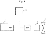
- FIG. 2 is a schematic diagram of a voltage system of the flying object 10.
- the flying object 10 is not particularly limited as long as it is an object capable of flying in air.
- the flying object 10 includes a typical airplane and an airplane, such as, a light aircraft and a drone.
- FIG. 1 shows the flying object 10 in an embodiment of an airplane.
- the flying object 10 includes a fuel cell 1, a secondary battery 2, a motor 3 that drives a propulsion propeller 4, an air resistance increasing device capable of increasing air resistance, and a control unit. Further, as shown in FIG. 2 , the fuel cell 1, the secondary battery 2, and the motor 3 are electrically connected, the motor 3 is intended to drive by obtaining power from at least one of the fuel cell 1 and the secondary battery 2.
- FIG. 2 shows a fuel-cell DC/DC converter (FDC) and an inverter (INV) together, which are common.
- FDC fuel-cell DC/DC converter
- IV inverter
- the fuel cell 1 is formed by laminating a plurality of fuel cell single cells (sometimes simply referred to as "single cell") in series.
- the single cell includes an electrolyte membrane, an anode disposed on one side of the electrolyte membrane, and a cathode disposed on the other side of the electrolyte membrane.
- catalyst layers are disposed on both surfaces of the electrolyte membrane
- diffusion layers are disposed outside the catalyst layers
- separators are further disposed outside the diffusion layers.
- the separator is provided with a fuel gas channel and an oxidant gas channel.
- This is a general configuration of a fuel cell.
- the catalyst layer and the diffusion layer function as an anode or a cathode.
- electrolyte membrane there is no particular limitation on the electrolyte membrane, the catalyst layer, the diffusion layer, or the separator disposed in the fuel cell, and any known one may be used.
- an ion exchange membrane made of a solid polymer material may be employed as an electrolyte membrane.
- the catalyst layer include a platinum-based catalyst.
- the diffusion layer include a porous material such as a carbon material.
- the separator include a metal material, such as a stainless steel, and a carbon material, such as a carbon composite material.
- a fuel gas is supplied to the anode, and an oxidant gas is supplied to the cathode, whereby an electrochemical reaction occurs and power is generated.
- the generated power is used for charging the secondary battery 2 and driving the motor 3. It may also be used in another device of the flying object 10.
- the secondary battery 2 is a known secondary battery, such as a lithium ion secondary battery.
- the secondary battery 2 plays a role in driving the motor 3 and storing electric power generated by the fuel cell 1. It may also be used in another device of the flying object 10.
- the air resistance increasing device is not particularly limited as long as it is a flight control surface capable of increasing the air resistance of the flying object 10.
- the air resistance increasing device may a secondary control surface 5.
- the secondary control surface is an auxiliary control surface other than the primary control surface of the flight control surface.
- Examples of the secondary control surface 5 include spoilers, flaps, tabs, and the like.
- FIG. 1 shows an example in which a spoiler is used as the secondary control blade surface 5.
- the secondary control surface 5 is provided on each of a pair of main wings 6, a pair of horizontal stabilizers 7, and a vertical stabilizer 8.
- the secondary control surface 5 is constituted of a pair of flat plates, and usually controls the move of the flying object 10 by opening one or both flat plates to change the air resistance. As shown in FIG.
- the secondary control surfaces 5 provided on the main wings 6 and the horizontal stabilizers 7 have vertically arranged flat plates, and the secondary control surfaces 5 provided on the vertical stabilizer 8 have flat plates arranged on the right and left.
- Such a configuration is similar to that of a general secondary control surface.
- the control unit is a computer system including a CPU, a ROM, a RAM, an input/output interface, and the like, and controls each unit of the flying object 10.
- the power generated by the fuel cell 1 may be used to charge the secondary battery 2.
- the power generation of the fuel cell 1 is controlled such that the secondary battery 2 does not exceed the charging allowable power.
- the power is generated for high potential avoidance, refreshing operation, rapid warm-up, or the like of the fuel cell 1, and the power generation amount becomes a power amount exceeding the power consumption amount.
- the allowable charge amount is exceeded and overcharged.
- the suppression of the ignition of such a secondary battery 2 is an important problem for enhancing the safety of the flying object 10.
- the control unit increases the amount of power supplied from the fuel cell 1 to the motor 3 and operates the air resistance increasing device to increase the air resistance to maintain the flight state as a power consumption control. This consumes the excess power while maintaining the flight state, thus allowing the suppressed ignition of the secondary battery due to overcharging.
- the "allowable charge amount” is an amount of charge within a range that does not cause overcharge. That is, when the amount of charge exceeds the allowable charge amount, the secondary battery 2 is overcharged.
- the "power consumption amount” is a power consumption amount required for an operation of the flying object 10.
- the power consumption amount varies depending on states of operation of the flying object 10 and the like.
- the "excess power amount” means a part of the power amount exceeding the power consumption amount when the fuel cell 1 generates power in excess of the power consumption amount.
- the "high potential avoidance” is a power generation to avoid a voltage of the fuel cell 1 rising above a predetermined voltage. This is because when the voltage of the fuel cell 1 rises to a predetermined voltage, a metal (e.g., platinum) used in the catalyst layer is ionized and eluted.
- a metal e.g., platinum
- the "refreshing operation” is a power generation for lowering the voltage of the fuel cell 1 for removing an oxide film of a metal (e.g., platinum) used in the catalyst layer.
- a metal e.g., platinum
- the "rapid warm-up" is a power generation for self-heating in order to prevent freezing of the fuel cell 1.
- the "power consumption control” is a control for consuming an excess power performed by the control unit.
- the thrust increase control for increasing an amount of power supplied from the fuel cell 1 to the motor 3 and the air resistance increase control for increasing an air resistance by operating the air resistance increasing device are performed.
- the “maintain the flight state” means that the thrust and the lift remain almost unchanged before and after the power consumption control.
- the “remain almost unchanged” means that the thrust and the lift change within ⁇ 10%, preferably within ⁇ 5%, before and after the power consumption control.
- the power consumption control is a control to increase the thrust or the lift of the flying object 10 and increases the air resistance to consume the excess power for maintaining the flight state.
- the order of performing the thrust increase control and the air resistance increase control is not particularly limited, they may be performed in order, or they may be simultaneously performed. If they are performed in order, either control may be performed first.
- the increase amount of the amount of power supplied to the motor 3 may be a part or a total amount of the excess power.
- the air resistance device includes the secondary control surfaces 5, the air resistance can be increased by opening one or both of the secondary control surfaces 5.
- the secondary control surfaces 5 are both open.
- the secondary control surfaces 5 are both open.
- the power consumption control can be performed without providing an additional device.
- control unit may perform the power consumption control as follows. That is, the control unit may perform the power consumption control when the excess power amount exceeds a first threshold value, and may stop the power consumption control when the excess power amount falls below a second threshold value. This allows overcharging of the secondary battery to be suppressed while suppressing the number and time of the power consumption control, thus making it possible to improve the fuel consumption.
- the "first threshold value" can be appropriately set from a range of an allowable charge amount in which the overcharge of the secondary battery 2 can be suppressed by performing the power consumption control when the excess power occurs, considering the fuel consumption. For example, it may be appropriately selected from a range of 30% to 70% of the allowable charge amount, preferably from a range of 40% to 60%.
- the "second threshold value" can be appropriately set from the range of the allowable charge amount in which the overcharge of the secondary battery 2 can be suppressed without performing the power consumption control when the excess power occurs, considering the fuel consumption. For example, it may be appropriately selected from a range of 0% to 30% of the allowable charge amount, preferably from a range of 10% to 20%.
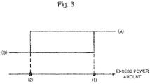
- FIG. 3 shows a diagram illustrating the power consumption control in which the threshold values are set.
- (1) and (2) in FIG. 3 show the first threshold value and the second threshold value, respectively.
- (A) and (B) in FIG. 3 show the excess power amount during the power consumption control and the excess power amount when the power consumption control is stopped, respectively.
- the power consumption control with the set threshold values is controlled to draw a hysteresis loop.
- FIG. 4 shows an example of the processing routine of the power consumption control with the set threshold values.
- a control unit 50 includes processes S1 to S6, and the control unit 50 repeatedly performs these processes.
- the process S1 it is determined whether or not the excess power amount exceeds the first threshold value. If the excess power amount is determined to exceed the first threshold value, the power consumption control is performed (processes S2 and S3).
- the thrust increase control for increasing the amount of power supplied from the fuel cell 1 to the motor 3 is performed.
- the air resistance increasing control is performed to increase the air resistance by operating the air resistance increasing device.
- the control is performed so as to maintain the flight state.
- process S4 it is determined whether or not the excess power amount is lower than the second threshold value. If the excess power amount is below the second threshold value, the power consumption control is stopped (processes S5 and S6).
- the thrust increase control is stopped.
- the air resistance increase control is stopped.
- the flying object 10 as an embodiment of the flying object of the present disclosure has been described.
- the flying object of the present disclosure performs the predetermined power consumption control when the fuel cell generates an amount of power exceeding the power consumption amount, that is, when the excess power amount occurs. Therefore, the flying object of the present disclosure allows the excess power amount to be consumed while maintaining the flight state, thus making it possible to suppress the ignition of the secondary battery due to overcharging.
Landscapes
- Engineering & Computer Science (AREA)
- Sustainable Energy (AREA)
- Life Sciences & Earth Sciences (AREA)
- Sustainable Development (AREA)
- Aviation & Aerospace Engineering (AREA)
- General Chemical & Material Sciences (AREA)
- Chemical & Material Sciences (AREA)
- Chemical Kinetics & Catalysis (AREA)
- Electrochemistry (AREA)
- Power Engineering (AREA)
- Transportation (AREA)
- Mechanical Engineering (AREA)
- Manufacturing & Machinery (AREA)
- Fuel Cell (AREA)
- Hybrid Cells (AREA)
Abstract
Description
- This application relates to a flying object.
- Recently, development of an aircraft with a fuel cell system has been promoted. For example,
Patent Document 1 describes a power supply system including a battery and a fuel cell for an aircraft. - Patent Literature 1:
JP 2007-15423 A - In a flying object including a fuel cell and a secondary battery, when an excess power generated for the purpose of high potential avoidance, refreshing operation, rapid warm-up of the fuel cell, or the like is charged in the secondary battery, there is a problem that ignition due to overcharging occurs. Such problems are important issues and related to safety.
- In view of the above circumstances, it is a main object of the present application to provide a flying object capable of suppressing ignition of a secondary battery due to overcharging.
- The present disclosure provides, as one means for solving the above problems, a flying object. The flying object includes a fuel cell, a secondary battery, a motor, an air resistance increasing device, and a control unit. The motor drives a propulsion propeller. The air resistance increasing device is capable of increasing the air resistance. The fuel cell, the secondary battery, and the motor are electrically connected. The motor is driven by obtaining power from at least one of the fuel cell and the secondary battery. When the fuel cell generates an amount of power exceeding a power consumption amount, the control unit increases an amount of power supplied to the motor from the fuel cell while increasing the air resistance by operating the air resistance increasing device, and performs a power consumption control to maintain a flight state.
- In the above-described flying object, the air resistance increasing device may include secondary control surfaces, and the air resistance may be increased by opening both the secondary control surfaces during the power consumption control. When the fuel cell generates an amount of power exceeding the power consumption amount and a part of the amount of power exceeding the power consumption amount is defined as an excess power amount, the control unit may perform the power consumption control when the excess power amount exceeds a first threshold value and may stop the power consumption control when the excess power amount falls below a second threshold value.
- The flying object of the present disclosure performs a predetermined power consumption control when the fuel cell generates an amount of power exceeding the power consumption amount, that is, when the excess power amount is generated. This allows the excess power to be consumed, thus making it possible to suppress the ignition of the secondary battery due to overcharging.
-
-
FIG. 1 is a schematic diagram of aflying object 10.FIG. 1A is a front view of theflying object 10, andFIG. 1B is a top view of theflying object 10. -
FIG. 2 is a schematic diagram of a voltage system of theflying object 10. -
FIG. 3 is a diagram for describing a power consumption control with set threshold values. -
FIG. 4 is an example of a processing routine of the power consumption control with the set threshold values. - A flying object of the present disclosure will be described using a
flying object 10 as an embodiment.FIG. 1 shows a schematic view of theflying object 10.FIG. 1A is a front view of theflying object 10, andFIG. 1B is a top view of theflying object 10.FIG. 2 is a schematic diagram of a voltage system of theflying object 10. - The
flying object 10 is not particularly limited as long as it is an object capable of flying in air. For example, theflying object 10 includes a typical airplane and an airplane, such as, a light aircraft and a drone.FIG. 1 shows theflying object 10 in an embodiment of an airplane. - The
flying object 10 includes afuel cell 1, asecondary battery 2, a motor 3 that drives apropulsion propeller 4, an air resistance increasing device capable of increasing air resistance, and a control unit. Further, as shown inFIG. 2 , thefuel cell 1, thesecondary battery 2, and the motor 3 are electrically connected, the motor 3 is intended to drive by obtaining power from at least one of thefuel cell 1 and thesecondary battery 2. Incidentally,FIG. 2 shows a fuel-cell DC/DC converter (FDC) and an inverter (INV) together, which are common. - The
fuel cell 1 is formed by laminating a plurality of fuel cell single cells (sometimes simply referred to as "single cell") in series. The single cell includes an electrolyte membrane, an anode disposed on one side of the electrolyte membrane, and a cathode disposed on the other side of the electrolyte membrane. Specifically, catalyst layers are disposed on both surfaces of the electrolyte membrane, diffusion layers are disposed outside the catalyst layers, and separators are further disposed outside the diffusion layers. The separator is provided with a fuel gas channel and an oxidant gas channel. This is a general configuration of a fuel cell. Here, in the fuel cell, the catalyst layer and the diffusion layer function as an anode or a cathode. - There is no particular limitation on the electrolyte membrane, the catalyst layer, the diffusion layer, or the separator disposed in the fuel cell, and any known one may be used. For example, an ion exchange membrane made of a solid polymer material may be employed as an electrolyte membrane. Examples of the catalyst layer include a platinum-based catalyst. Examples of the diffusion layer include a porous material such as a carbon material. Examples of the separator include a metal material, such as a stainless steel, and a carbon material, such as a carbon composite material.
- In the
fuel cell 1, a fuel gas is supplied to the anode, and an oxidant gas is supplied to the cathode, whereby an electrochemical reaction occurs and power is generated. The generated power is used for charging thesecondary battery 2 and driving the motor 3. It may also be used in another device of theflying object 10. - The
secondary battery 2 is a known secondary battery, such as a lithium ion secondary battery. Thesecondary battery 2 plays a role in driving the motor 3 and storing electric power generated by thefuel cell 1. It may also be used in another device of theflying object 10. - The air resistance increasing device is not particularly limited as long as it is a flight control surface capable of increasing the air resistance of the
flying object 10. For example, the air resistance increasing device may asecondary control surface 5. The secondary control surface is an auxiliary control surface other than the primary control surface of the flight control surface. Examples of thesecondary control surface 5 include spoilers, flaps, tabs, and the like.FIG. 1 shows an example in which a spoiler is used as the secondarycontrol blade surface 5. InFIG. 1 , thesecondary control surface 5 is provided on each of a pair ofmain wings 6, a pair ofhorizontal stabilizers 7, and avertical stabilizer 8. Thesecondary control surface 5 is constituted of a pair of flat plates, and usually controls the move of the flyingobject 10 by opening one or both flat plates to change the air resistance. As shown inFIG. 1 , thesecondary control surfaces 5 provided on themain wings 6 and thehorizontal stabilizers 7 have vertically arranged flat plates, and thesecondary control surfaces 5 provided on thevertical stabilizer 8 have flat plates arranged on the right and left. Such a configuration is similar to that of a general secondary control surface. - The control unit is a computer system including a CPU, a ROM, a RAM, an input/output interface, and the like, and controls each unit of the flying
object 10. - As described above, the power generated by the
fuel cell 1 may be used to charge thesecondary battery 2. Normally, the power generation of thefuel cell 1 is controlled such that thesecondary battery 2 does not exceed the charging allowable power. However, assume that the power is generated for high potential avoidance, refreshing operation, rapid warm-up, or the like of thefuel cell 1, and the power generation amount becomes a power amount exceeding the power consumption amount. When a portion of the power amount (excess power amount) that exceeds the power consumption amount is charged into thesecondary battery 2, there is a case where the allowable charge amount is exceeded and overcharged. Then, there is a problem that ignition occurs when thesecondary battery 2 is overcharged. The suppression of the ignition of such asecondary battery 2 is an important problem for enhancing the safety of the flyingobject 10. - Therefore, in the flying
object 10, when thefuel cell 1 generates an amount of power exceeding the power consumption amount, the control unit increases the amount of power supplied from thefuel cell 1 to the motor 3 and operates the air resistance increasing device to increase the air resistance to maintain the flight state as a power consumption control. This consumes the excess power while maintaining the flight state, thus allowing the suppressed ignition of the secondary battery due to overcharging. - Here, each term will be described.
- The "allowable charge amount" is an amount of charge within a range that does not cause overcharge. That is, when the amount of charge exceeds the allowable charge amount, the
secondary battery 2 is overcharged. - The "power consumption amount" is a power consumption amount required for an operation of the flying
object 10. The power consumption amount varies depending on states of operation of the flyingobject 10 and the like. - The "excess power amount" means a part of the power amount exceeding the power consumption amount when the
fuel cell 1 generates power in excess of the power consumption amount. - The "high potential avoidance" is a power generation to avoid a voltage of the
fuel cell 1 rising above a predetermined voltage. This is because when the voltage of thefuel cell 1 rises to a predetermined voltage, a metal (e.g., platinum) used in the catalyst layer is ionized and eluted. - The "refreshing operation" is a power generation for lowering the voltage of the
fuel cell 1 for removing an oxide film of a metal (e.g., platinum) used in the catalyst layer. - The "rapid warm-up" is a power generation for self-heating in order to prevent freezing of the
fuel cell 1. - The "power consumption control" is a control for consuming an excess power performed by the control unit. In the power consumption control, the thrust increase control for increasing an amount of power supplied from the
fuel cell 1 to the motor 3 and the air resistance increase control for increasing an air resistance by operating the air resistance increasing device are performed. At this time, it is necessary to carry out the thrust increase control and the air resistance increase control so as to maintain the flight state. The "maintain the flight state" means that the thrust and the lift remain almost unchanged before and after the power consumption control. The "remain almost unchanged" means that the thrust and the lift change within ±10%, preferably within ±5%, before and after the power consumption control. - Therefore, it can be said that the power consumption control is a control to increase the thrust or the lift of the flying
object 10 and increases the air resistance to consume the excess power for maintaining the flight state. Here, the order of performing the thrust increase control and the air resistance increase control is not particularly limited, they may be performed in order, or they may be simultaneously performed. If they are performed in order, either control may be performed first. - Although there is no particular limitation on the increase amount of the amount of power supplied to the motor 3, it may be a part or a total amount of the excess power. When the air resistance device includes the
secondary control surfaces 5, the air resistance can be increased by opening one or both of the secondary control surfaces 5. Preferably, thesecondary control surfaces 5 are both open. As shown inFIG. 1 , when a plurality ofsecondary control surfaces 5 are provided in the flyingobject 10, all thesecondary control surfaces 5 provided in the flyingobject 10 may be opened, or a part of thesecondary control surfaces 5 may be opened. By using thesecondary control surface 5 as an air resistance increasing device, the power consumption control can be performed without providing an additional device. - Further, the control unit may perform the power consumption control as follows. That is, the control unit may perform the power consumption control when the excess power amount exceeds a first threshold value, and may stop the power consumption control when the excess power amount falls below a second threshold value. This allows overcharging of the secondary battery to be suppressed while suppressing the number and time of the power consumption control, thus making it possible to improve the fuel consumption.
- The "first threshold value" can be appropriately set from a range of an allowable charge amount in which the overcharge of the
secondary battery 2 can be suppressed by performing the power consumption control when the excess power occurs, considering the fuel consumption. For example, it may be appropriately selected from a range of 30% to 70% of the allowable charge amount, preferably from a range of 40% to 60%. - The "second threshold value" can be appropriately set from the range of the allowable charge amount in which the overcharge of the
secondary battery 2 can be suppressed without performing the power consumption control when the excess power occurs, considering the fuel consumption. For example, it may be appropriately selected from a range of 0% to 30% of the allowable charge amount, preferably from a range of 10% to 20%. -
FIG. 3 shows a diagram illustrating the power consumption control in which the threshold values are set. (1) and (2) inFIG. 3 show the first threshold value and the second threshold value, respectively. In addition, (A) and (B) inFIG. 3 show the excess power amount during the power consumption control and the excess power amount when the power consumption control is stopped, respectively. As shown inFIG. 3 , the power consumption control with the set threshold values is controlled to draw a hysteresis loop. - Further,
FIG. 4 shows an example of the processing routine of the power consumption control with the set threshold values. As shown inFIG. 4 , a control unit 50 includes processes S1 to S6, and the control unit 50 repeatedly performs these processes. - In the process S1, it is determined whether or not the excess power amount exceeds the first threshold value. If the excess power amount is determined to exceed the first threshold value, the power consumption control is performed (processes S2 and S3).
- In the process S2, the thrust increase control for increasing the amount of power supplied from the
fuel cell 1 to the motor 3 is performed. In the process S3, the air resistance increasing control is performed to increase the air resistance by operating the air resistance increasing device. Here, when both of the processes S2 and S3 are performed, the control is performed so as to maintain the flight state. - In the process S4, it is determined whether or not the excess power amount is lower than the second threshold value. If the excess power amount is below the second threshold value, the power consumption control is stopped (processes S5 and S6).
- In the process S5, the thrust increase control is stopped. In the process S6, the air resistance increase control is stopped. Here, in performing both of the processes S5 and S6, it is preferred to control so as to maintain the flight state.
- As described above, the flying
object 10 as an embodiment of the flying object of the present disclosure has been described. The flying object of the present disclosure performs the predetermined power consumption control when the fuel cell generates an amount of power exceeding the power consumption amount, that is, when the excess power amount occurs. Therefore, the flying object of the present disclosure allows the excess power amount to be consumed while maintaining the flight state, thus making it possible to suppress the ignition of the secondary battery due to overcharging. -
- 1 Fuel cell
- 2 Secondary battery
- 3 Motor
- 4 Propeller
- 5 Secondary control surface
- 6 Main wing
- 7 Horizontal stabilizer
- 8 Vertical stabilizer
- 10 Flying object
Claims (3)
- A flying object comprising:a fuel cell;a secondary battery;a motor that drives a propulsion propeller;an air resistance increasing device capable of increasing the air resistance; anda control unit,wherein the fuel cell, the secondary battery, and the motor are electrically connected,the motor is driven by obtaining power from at least one of the fuel cell and the secondary battery, andwhen the fuel cell generates an amount of power exceeding a power consumption amount, the control unit increases an amount of power supplied to the motor from the fuel cell while increasing the air resistance by operating the air resistance increasing device, and performs a power consumption control to maintain a flight state.
- The flying object according to claim 1, whereinthe air resistance increasing device includes secondary control surfaces, andthe air resistance is increased by opening both the secondary control surfaces during the power consumption control.
- The flying object according to claim 1 or 2, wherein
when the fuel cell generates an amount of power exceeding the power consumption amount and a part of the amount of power exceeding the power consumption amount is defined as an excess power amount, the control unit performs the power consumption control when the excess power amount exceeds a first threshold value and stops the power consumption control when the excess power amount falls below a second threshold value.
Applications Claiming Priority (2)
| Application Number | Priority Date | Filing Date | Title |
|---|---|---|---|
| JP2021076676 | 2021-04-28 | ||
| JP2022071561A JP7661925B2 (en) | 2021-04-28 | 2022-04-25 | Aircraft |
Publications (2)
| Publication Number | Publication Date |
|---|---|
| EP4082825A1 true EP4082825A1 (en) | 2022-11-02 |
| EP4082825B1 EP4082825B1 (en) | 2025-07-30 |
Family
ID=81388747
Family Applications (1)
| Application Number | Title | Priority Date | Filing Date |
|---|---|---|---|
| EP22170230.1A Active EP4082825B1 (en) | 2021-04-28 | 2022-04-27 | Flying object |
Country Status (3)
| Country | Link |
|---|---|
| US (1) | US20220348340A1 (en) |
| EP (1) | EP4082825B1 (en) |
| CN (1) | CN115246473A (en) |
Citations (3)
| Publication number | Priority date | Publication date | Assignee | Title |
|---|---|---|---|---|
| JP2007015423A (en) | 2005-07-05 | 2007-01-25 | Shin Meiwa Ind Co Ltd | Aircraft power system |
| US20110071707A1 (en) * | 2009-09-23 | 2011-03-24 | Adaptive Materials, Inc. | Method for Managing Power Boost in a Fuel Cell Powered Aerial Vehicle |
| US9604533B2 (en) * | 2014-06-24 | 2017-03-28 | Toyota Jidosha Kabushiki Kaisha | Vehicle and control method for vehicle |
Family Cites Families (6)
| Publication number | Priority date | Publication date | Assignee | Title |
|---|---|---|---|---|
| US9776526B2 (en) * | 2014-11-14 | 2017-10-03 | Toyota Jidosha Kabushiki Kaisha | Fuel cell system, fuel cell vehicle, and method of controlling fuel cell system |
| US20210269152A1 (en) * | 2018-06-27 | 2021-09-02 | H3 Dynamics Holdings Pte. Ltd. | Distributed electric energy pods network and associated electrically powered vehicle |
| US11352123B2 (en) * | 2018-06-28 | 2022-06-07 | Lucas Kai-Luen Hung | Wing assembly for a high endurance aircraft |
| US20200354073A1 (en) * | 2019-02-21 | 2020-11-12 | Valery Miftakhov | Redundant aviation powertrain system for reliability and safety |
| FR3097202B1 (en) * | 2019-06-14 | 2024-02-23 | Airbus | AUTONOMOUS PROPULSION SYSTEM FOR AN AIRCRAFT, SAID AUTONOMOUS PROPULSION SYSTEM COMPRISING A FUEL CELL |
| US11292356B2 (en) * | 2019-06-26 | 2022-04-05 | The Boeing Company | Energy-harvesting spoiler on a wing of an aircraft |
-
2022
- 2022-04-27 US US17/660,913 patent/US20220348340A1/en not_active Abandoned
- 2022-04-27 EP EP22170230.1A patent/EP4082825B1/en active Active
- 2022-04-27 CN CN202210452494.1A patent/CN115246473A/en active Pending
Patent Citations (3)
| Publication number | Priority date | Publication date | Assignee | Title |
|---|---|---|---|---|
| JP2007015423A (en) | 2005-07-05 | 2007-01-25 | Shin Meiwa Ind Co Ltd | Aircraft power system |
| US20110071707A1 (en) * | 2009-09-23 | 2011-03-24 | Adaptive Materials, Inc. | Method for Managing Power Boost in a Fuel Cell Powered Aerial Vehicle |
| US9604533B2 (en) * | 2014-06-24 | 2017-03-28 | Toyota Jidosha Kabushiki Kaisha | Vehicle and control method for vehicle |
Also Published As
| Publication number | Publication date |
|---|---|
| US20220348340A1 (en) | 2022-11-03 |
| CN115246473A (en) | 2022-10-28 |
| EP4082825B1 (en) | 2025-07-30 |
Similar Documents
| Publication | Publication Date | Title |
|---|---|---|
| US8400101B2 (en) | Power supply control circuit | |
| US20230411779A1 (en) | End cover, end cover assembly, battery cell, battery, and electric device | |
| US20250083572A1 (en) | Power source assembly for an aeronautical vehicle | |
| EP2192647B1 (en) | Fuel cell system | |
| CN106067557B (en) | Method and fuel cell system for controlling operating point switching of a fuel cell stack | |
| US8027759B2 (en) | Fuel cell vehicle system | |
| CN107452972B (en) | Fuel cell system and control method thereof | |
| CN101569044A (en) | Fuel cell system | |
| Gao et al. | A health-aware energy management strategy for fuel cell hybrid electric UAVs based on safe reinforcement learning | |
| US20120301803A1 (en) | Fuel cell system and control method thereof | |
| CN103907232B (en) | Fuel cell output control device | |
| CN109204065B (en) | Fuel cell system and control method for fuel cell system | |
| US9537310B2 (en) | Method of controlling the operation of a hybrid system | |
| KR20220095354A (en) | Airmobility power management system and operation method thereof | |
| EP1967407B2 (en) | Hybrid electrical power source | |
| JP7661925B2 (en) | Aircraft | |
| EP4082825B1 (en) | Flying object | |
| KR101851830B1 (en) | Fuel cell system and control method of the same | |
| CN121149311A (en) | A power balance method and system for a fuel cell system for hydrogen-powered unmanned aerial vehicles | |
| CN107492919A (en) | Power system and its control method | |
| US20260031724A1 (en) | Power source assembly for aeronautical vehicle | |
| JP2013171682A (en) | Fuel cell system and method for controlling fuel cell | |
| CA2870985C (en) | Fuel cell system | |
| EP4079558A1 (en) | Fuel cell system and air vehicle | |
| CN105609840B (en) | The method of operation of fuel cell system and fuel cell system |
Legal Events
| Date | Code | Title | Description |
|---|---|---|---|
| PUAI | Public reference made under article 153(3) epc to a published international application that has entered the european phase |
Free format text: ORIGINAL CODE: 0009012 |
|
| STAA | Information on the status of an ep patent application or granted ep patent |
Free format text: STATUS: REQUEST FOR EXAMINATION WAS MADE |
|
| 17P | Request for examination filed |
Effective date: 20220427 |
|
| AK | Designated contracting states |
Kind code of ref document: A1 Designated state(s): AL AT BE BG CH CY CZ DE DK EE ES FI FR GB GR HR HU IE IS IT LI LT LU LV MC MK MT NL NO PL PT RO RS SE SI SK SM TR |
|
| STAA | Information on the status of an ep patent application or granted ep patent |
Free format text: STATUS: EXAMINATION IS IN PROGRESS |
|
| 17Q | First examination report despatched |
Effective date: 20240222 |
|
| GRAP | Despatch of communication of intention to grant a patent |
Free format text: ORIGINAL CODE: EPIDOSNIGR1 |
|
| STAA | Information on the status of an ep patent application or granted ep patent |
Free format text: STATUS: GRANT OF PATENT IS INTENDED |
|
| INTG | Intention to grant announced |
Effective date: 20250317 |
|
| GRAS | Grant fee paid |
Free format text: ORIGINAL CODE: EPIDOSNIGR3 |
|
| GRAA | (expected) grant |
Free format text: ORIGINAL CODE: 0009210 |
|
| STAA | Information on the status of an ep patent application or granted ep patent |
Free format text: STATUS: THE PATENT HAS BEEN GRANTED |
|
| AK | Designated contracting states |
Kind code of ref document: B1 Designated state(s): AL AT BE BG CH CY CZ DE DK EE ES FI FR GB GR HR HU IE IS IT LI LT LU LV MC MK MT NL NO PL PT RO RS SE SI SK SM TR |
|
| REG | Reference to a national code |
Ref country code: GB Ref legal event code: FG4D |
|
| REG | Reference to a national code |
Ref country code: CH Ref legal event code: EP |
|
| REG | Reference to a national code |
Ref country code: DE Ref legal event code: R096 Ref document number: 602022018292 Country of ref document: DE |
|
| REG | Reference to a national code |
Ref country code: IE Ref legal event code: FG4D |
|
| REG | Reference to a national code |
Ref country code: NL Ref legal event code: MP Effective date: 20250730 |
|
| REG | Reference to a national code |
Ref country code: AT Ref legal event code: MK05 Ref document number: 1818595 Country of ref document: AT Kind code of ref document: T Effective date: 20250730 |
|
| PG25 | Lapsed in a contracting state [announced via postgrant information from national office to epo] |
Ref country code: PT Free format text: LAPSE BECAUSE OF FAILURE TO SUBMIT A TRANSLATION OF THE DESCRIPTION OR TO PAY THE FEE WITHIN THE PRESCRIBED TIME-LIMIT Effective date: 20251202 |
|
| PG25 | Lapsed in a contracting state [announced via postgrant information from national office to epo] |
Ref country code: IS Free format text: LAPSE BECAUSE OF FAILURE TO SUBMIT A TRANSLATION OF THE DESCRIPTION OR TO PAY THE FEE WITHIN THE PRESCRIBED TIME-LIMIT Effective date: 20251130 |
|
| PG25 | Lapsed in a contracting state [announced via postgrant information from national office to epo] |
Ref country code: NO Free format text: LAPSE BECAUSE OF FAILURE TO SUBMIT A TRANSLATION OF THE DESCRIPTION OR TO PAY THE FEE WITHIN THE PRESCRIBED TIME-LIMIT Effective date: 20251030 |
|
| REG | Reference to a national code |
Ref country code: LT Ref legal event code: MG9D |
|
| PG25 | Lapsed in a contracting state [announced via postgrant information from national office to epo] |
Ref country code: AT Free format text: LAPSE BECAUSE OF FAILURE TO SUBMIT A TRANSLATION OF THE DESCRIPTION OR TO PAY THE FEE WITHIN THE PRESCRIBED TIME-LIMIT Effective date: 20250730 |
|
| PG25 | Lapsed in a contracting state [announced via postgrant information from national office to epo] |
Ref country code: FI Free format text: LAPSE BECAUSE OF FAILURE TO SUBMIT A TRANSLATION OF THE DESCRIPTION OR TO PAY THE FEE WITHIN THE PRESCRIBED TIME-LIMIT Effective date: 20250730 |
|
| PG25 | Lapsed in a contracting state [announced via postgrant information from national office to epo] |
Ref country code: NL Free format text: LAPSE BECAUSE OF FAILURE TO SUBMIT A TRANSLATION OF THE DESCRIPTION OR TO PAY THE FEE WITHIN THE PRESCRIBED TIME-LIMIT Effective date: 20250730 Ref country code: HR Free format text: LAPSE BECAUSE OF FAILURE TO SUBMIT A TRANSLATION OF THE DESCRIPTION OR TO PAY THE FEE WITHIN THE PRESCRIBED TIME-LIMIT Effective date: 20250730 |
|
| PG25 | Lapsed in a contracting state [announced via postgrant information from national office to epo] |
Ref country code: GR Free format text: LAPSE BECAUSE OF FAILURE TO SUBMIT A TRANSLATION OF THE DESCRIPTION OR TO PAY THE FEE WITHIN THE PRESCRIBED TIME-LIMIT Effective date: 20251031 |
|
| PG25 | Lapsed in a contracting state [announced via postgrant information from national office to epo] |
Ref country code: SE Free format text: LAPSE BECAUSE OF FAILURE TO SUBMIT A TRANSLATION OF THE DESCRIPTION OR TO PAY THE FEE WITHIN THE PRESCRIBED TIME-LIMIT Effective date: 20250730 |
|
| PG25 | Lapsed in a contracting state [announced via postgrant information from national office to epo] |
Ref country code: LV Free format text: LAPSE BECAUSE OF FAILURE TO SUBMIT A TRANSLATION OF THE DESCRIPTION OR TO PAY THE FEE WITHIN THE PRESCRIBED TIME-LIMIT Effective date: 20250730 |
|
| PG25 | Lapsed in a contracting state [announced via postgrant information from national office to epo] |
Ref country code: BG Free format text: LAPSE BECAUSE OF FAILURE TO SUBMIT A TRANSLATION OF THE DESCRIPTION OR TO PAY THE FEE WITHIN THE PRESCRIBED TIME-LIMIT Effective date: 20250730 Ref country code: PL Free format text: LAPSE BECAUSE OF FAILURE TO SUBMIT A TRANSLATION OF THE DESCRIPTION OR TO PAY THE FEE WITHIN THE PRESCRIBED TIME-LIMIT Effective date: 20250730 |
|
| PG25 | Lapsed in a contracting state [announced via postgrant information from national office to epo] |
Ref country code: RS Free format text: LAPSE BECAUSE OF FAILURE TO SUBMIT A TRANSLATION OF THE DESCRIPTION OR TO PAY THE FEE WITHIN THE PRESCRIBED TIME-LIMIT Effective date: 20251030 |
|
| PG25 | Lapsed in a contracting state [announced via postgrant information from national office to epo] |
Ref country code: ES Free format text: LAPSE BECAUSE OF FAILURE TO SUBMIT A TRANSLATION OF THE DESCRIPTION OR TO PAY THE FEE WITHIN THE PRESCRIBED TIME-LIMIT Effective date: 20250730 |
|
| PG25 | Lapsed in a contracting state [announced via postgrant information from national office to epo] |
Ref country code: SM Free format text: LAPSE BECAUSE OF FAILURE TO SUBMIT A TRANSLATION OF THE DESCRIPTION OR TO PAY THE FEE WITHIN THE PRESCRIBED TIME-LIMIT Effective date: 20250730 |
|
| PGFP | Annual fee paid to national office [announced via postgrant information from national office to epo] |
Ref country code: GB Payment date: 20260313 Year of fee payment: 5 |
|
| PG25 | Lapsed in a contracting state [announced via postgrant information from national office to epo] |
Ref country code: DK Free format text: LAPSE BECAUSE OF FAILURE TO SUBMIT A TRANSLATION OF THE DESCRIPTION OR TO PAY THE FEE WITHIN THE PRESCRIBED TIME-LIMIT Effective date: 20250730 |
|
| PG25 | Lapsed in a contracting state [announced via postgrant information from national office to epo] |
Ref country code: IT Free format text: LAPSE BECAUSE OF FAILURE TO SUBMIT A TRANSLATION OF THE DESCRIPTION OR TO PAY THE FEE WITHIN THE PRESCRIBED TIME-LIMIT Effective date: 20250730 |
|
| PGFP | Annual fee paid to national office [announced via postgrant information from national office to epo] |
Ref country code: FR Payment date: 20260309 Year of fee payment: 5 |
|
| PG25 | Lapsed in a contracting state [announced via postgrant information from national office to epo] |
Ref country code: CZ Free format text: LAPSE BECAUSE OF FAILURE TO SUBMIT A TRANSLATION OF THE DESCRIPTION OR TO PAY THE FEE WITHIN THE PRESCRIBED TIME-LIMIT Effective date: 20250730 |
|
| PG25 | Lapsed in a contracting state [announced via postgrant information from national office to epo] |
Ref country code: SK Free format text: LAPSE BECAUSE OF FAILURE TO SUBMIT A TRANSLATION OF THE DESCRIPTION OR TO PAY THE FEE WITHIN THE PRESCRIBED TIME-LIMIT Effective date: 20250730 Ref country code: EE Free format text: LAPSE BECAUSE OF FAILURE TO SUBMIT A TRANSLATION OF THE DESCRIPTION OR TO PAY THE FEE WITHIN THE PRESCRIBED TIME-LIMIT Effective date: 20250730 |