EP4082668A1 - Electric dust collector - Google Patents
Electric dust collector Download PDFInfo
- Publication number
- EP4082668A1 EP4082668A1 EP21858044.7A EP21858044A EP4082668A1 EP 4082668 A1 EP4082668 A1 EP 4082668A1 EP 21858044 A EP21858044 A EP 21858044A EP 4082668 A1 EP4082668 A1 EP 4082668A1
- Authority
- EP
- European Patent Office
- Prior art keywords
- collection
- charging
- electrodes
- electrode
- electrostatic precipitator
- Prior art date
- Legal status (The legal status is an assumption and is not a legal conclusion. Google has not performed a legal analysis and makes no representation as to the accuracy of the status listed.)
- Withdrawn
Links
Images




Classifications
-
- B—PERFORMING OPERATIONS; TRANSPORTING
- B03—SEPARATION OF SOLID MATERIALS USING LIQUIDS OR USING PNEUMATIC TABLES OR JIGS; MAGNETIC OR ELECTROSTATIC SEPARATION OF SOLID MATERIALS FROM SOLID MATERIALS OR FLUIDS; SEPARATION BY HIGH-VOLTAGE ELECTRIC FIELDS
- B03C—MAGNETIC OR ELECTROSTATIC SEPARATION OF SOLID MATERIALS FROM SOLID MATERIALS OR FLUIDS; SEPARATION BY HIGH-VOLTAGE ELECTRIC FIELDS
- B03C3/00—Separating dispersed particles from gases or vapour, e.g. air, by electrostatic effect
- B03C3/02—Plant or installations having external electricity supply
- B03C3/04—Plant or installations having external electricity supply dry type
- B03C3/06—Plant or installations having external electricity supply dry type characterised by presence of stationary tube electrodes
-
- B—PERFORMING OPERATIONS; TRANSPORTING
- B03—SEPARATION OF SOLID MATERIALS USING LIQUIDS OR USING PNEUMATIC TABLES OR JIGS; MAGNETIC OR ELECTROSTATIC SEPARATION OF SOLID MATERIALS FROM SOLID MATERIALS OR FLUIDS; SEPARATION BY HIGH-VOLTAGE ELECTRIC FIELDS
- B03C—MAGNETIC OR ELECTROSTATIC SEPARATION OF SOLID MATERIALS FROM SOLID MATERIALS OR FLUIDS; SEPARATION BY HIGH-VOLTAGE ELECTRIC FIELDS
- B03C3/00—Separating dispersed particles from gases or vapour, e.g. air, by electrostatic effect
- B03C3/02—Plant or installations having external electricity supply
- B03C3/04—Plant or installations having external electricity supply dry type
- B03C3/08—Plant or installations having external electricity supply dry type characterised by presence of stationary flat electrodes arranged with their flat surfaces parallel to the gas stream
-
- B—PERFORMING OPERATIONS; TRANSPORTING
- B03—SEPARATION OF SOLID MATERIALS USING LIQUIDS OR USING PNEUMATIC TABLES OR JIGS; MAGNETIC OR ELECTROSTATIC SEPARATION OF SOLID MATERIALS FROM SOLID MATERIALS OR FLUIDS; SEPARATION BY HIGH-VOLTAGE ELECTRIC FIELDS
- B03C—MAGNETIC OR ELECTROSTATIC SEPARATION OF SOLID MATERIALS FROM SOLID MATERIALS OR FLUIDS; SEPARATION BY HIGH-VOLTAGE ELECTRIC FIELDS
- B03C3/00—Separating dispersed particles from gases or vapour, e.g. air, by electrostatic effect
- B03C3/02—Plant or installations having external electricity supply
- B03C3/04—Plant or installations having external electricity supply dry type
- B03C3/12—Plant or installations having external electricity supply dry type characterised by separation of ionising and collecting stations
-
- B—PERFORMING OPERATIONS; TRANSPORTING
- B03—SEPARATION OF SOLID MATERIALS USING LIQUIDS OR USING PNEUMATIC TABLES OR JIGS; MAGNETIC OR ELECTROSTATIC SEPARATION OF SOLID MATERIALS FROM SOLID MATERIALS OR FLUIDS; SEPARATION BY HIGH-VOLTAGE ELECTRIC FIELDS
- B03C—MAGNETIC OR ELECTROSTATIC SEPARATION OF SOLID MATERIALS FROM SOLID MATERIALS OR FLUIDS; SEPARATION BY HIGH-VOLTAGE ELECTRIC FIELDS
- B03C3/00—Separating dispersed particles from gases or vapour, e.g. air, by electrostatic effect
- B03C3/34—Constructional details or accessories or operation thereof
- B03C3/40—Electrode constructions
- B03C3/41—Ionising-electrodes
-
- B—PERFORMING OPERATIONS; TRANSPORTING
- B03—SEPARATION OF SOLID MATERIALS USING LIQUIDS OR USING PNEUMATIC TABLES OR JIGS; MAGNETIC OR ELECTROSTATIC SEPARATION OF SOLID MATERIALS FROM SOLID MATERIALS OR FLUIDS; SEPARATION BY HIGH-VOLTAGE ELECTRIC FIELDS
- B03C—MAGNETIC OR ELECTROSTATIC SEPARATION OF SOLID MATERIALS FROM SOLID MATERIALS OR FLUIDS; SEPARATION BY HIGH-VOLTAGE ELECTRIC FIELDS
- B03C3/00—Separating dispersed particles from gases or vapour, e.g. air, by electrostatic effect
- B03C3/34—Constructional details or accessories or operation thereof
- B03C3/40—Electrode constructions
- B03C3/45—Collecting-electrodes
- B03C3/47—Collecting-electrodes flat, e.g. plates, discs, gratings
-
- B—PERFORMING OPERATIONS; TRANSPORTING
- B03—SEPARATION OF SOLID MATERIALS USING LIQUIDS OR USING PNEUMATIC TABLES OR JIGS; MAGNETIC OR ELECTROSTATIC SEPARATION OF SOLID MATERIALS FROM SOLID MATERIALS OR FLUIDS; SEPARATION BY HIGH-VOLTAGE ELECTRIC FIELDS
- B03C—MAGNETIC OR ELECTROSTATIC SEPARATION OF SOLID MATERIALS FROM SOLID MATERIALS OR FLUIDS; SEPARATION BY HIGH-VOLTAGE ELECTRIC FIELDS
- B03C3/00—Separating dispersed particles from gases or vapour, e.g. air, by electrostatic effect
- B03C3/34—Constructional details or accessories or operation thereof
- B03C3/40—Electrode constructions
- B03C3/45—Collecting-electrodes
- B03C3/51—Catch- space electrodes, e.g. slotted-box form
-
- B—PERFORMING OPERATIONS; TRANSPORTING
- B03—SEPARATION OF SOLID MATERIALS USING LIQUIDS OR USING PNEUMATIC TABLES OR JIGS; MAGNETIC OR ELECTROSTATIC SEPARATION OF SOLID MATERIALS FROM SOLID MATERIALS OR FLUIDS; SEPARATION BY HIGH-VOLTAGE ELECTRIC FIELDS
- B03C—MAGNETIC OR ELECTROSTATIC SEPARATION OF SOLID MATERIALS FROM SOLID MATERIALS OR FLUIDS; SEPARATION BY HIGH-VOLTAGE ELECTRIC FIELDS
- B03C3/00—Separating dispersed particles from gases or vapour, e.g. air, by electrostatic effect
- B03C3/34—Constructional details or accessories or operation thereof
- B03C3/66—Applications of electricity supply techniques
- B03C3/68—Control systems therefor
-
- F—MECHANICAL ENGINEERING; LIGHTING; HEATING; WEAPONS; BLASTING
- F01—MACHINES OR ENGINES IN GENERAL; ENGINE PLANTS IN GENERAL; STEAM ENGINES
- F01N—GAS-FLOW SILENCERS OR EXHAUST APPARATUS FOR MACHINES OR ENGINES IN GENERAL; GAS-FLOW SILENCERS OR EXHAUST APPARATUS FOR INTERNAL-COMBUSTION ENGINES
- F01N13/00—Exhaust or silencing apparatus characterised by constructional features
- F01N13/004—Exhaust or silencing apparatus characterised by constructional features specially adapted for marine propulsion, i.e. for receiving simultaneously engine exhaust gases and engine cooling water
-
- F—MECHANICAL ENGINEERING; LIGHTING; HEATING; WEAPONS; BLASTING
- F01—MACHINES OR ENGINES IN GENERAL; ENGINE PLANTS IN GENERAL; STEAM ENGINES
- F01N—GAS-FLOW SILENCERS OR EXHAUST APPARATUS FOR MACHINES OR ENGINES IN GENERAL; GAS-FLOW SILENCERS OR EXHAUST APPARATUS FOR INTERNAL-COMBUSTION ENGINES
- F01N3/00—Exhaust or silencing apparatus having means for purifying, rendering innocuous, or otherwise treating exhaust
- F01N3/01—Exhaust or silencing apparatus having means for purifying, rendering innocuous, or otherwise treating exhaust by means of electric or electrostatic separators
-
- F—MECHANICAL ENGINEERING; LIGHTING; HEATING; WEAPONS; BLASTING
- F01—MACHINES OR ENGINES IN GENERAL; ENGINE PLANTS IN GENERAL; STEAM ENGINES
- F01N—GAS-FLOW SILENCERS OR EXHAUST APPARATUS FOR MACHINES OR ENGINES IN GENERAL; GAS-FLOW SILENCERS OR EXHAUST APPARATUS FOR INTERNAL-COMBUSTION ENGINES
- F01N3/00—Exhaust or silencing apparatus having means for purifying, rendering innocuous, or otherwise treating exhaust
- F01N3/08—Exhaust or silencing apparatus having means for purifying, rendering innocuous, or otherwise treating exhaust for rendering innocuous
-
- B—PERFORMING OPERATIONS; TRANSPORTING
- B03—SEPARATION OF SOLID MATERIALS USING LIQUIDS OR USING PNEUMATIC TABLES OR JIGS; MAGNETIC OR ELECTROSTATIC SEPARATION OF SOLID MATERIALS FROM SOLID MATERIALS OR FLUIDS; SEPARATION BY HIGH-VOLTAGE ELECTRIC FIELDS
- B03C—MAGNETIC OR ELECTROSTATIC SEPARATION OF SOLID MATERIALS FROM SOLID MATERIALS OR FLUIDS; SEPARATION BY HIGH-VOLTAGE ELECTRIC FIELDS
- B03C2201/00—Details of magnetic or electrostatic separation
- B03C2201/10—Ionising electrode with two or more serrated ends or sides
-
- B—PERFORMING OPERATIONS; TRANSPORTING
- B03—SEPARATION OF SOLID MATERIALS USING LIQUIDS OR USING PNEUMATIC TABLES OR JIGS; MAGNETIC OR ELECTROSTATIC SEPARATION OF SOLID MATERIALS FROM SOLID MATERIALS OR FLUIDS; SEPARATION BY HIGH-VOLTAGE ELECTRIC FIELDS
- B03C—MAGNETIC OR ELECTROSTATIC SEPARATION OF SOLID MATERIALS FROM SOLID MATERIALS OR FLUIDS; SEPARATION BY HIGH-VOLTAGE ELECTRIC FIELDS
- B03C2201/00—Details of magnetic or electrostatic separation
- B03C2201/24—Details of magnetic or electrostatic separation for measuring or calculating of parameters, e.g. efficiency
-
- F—MECHANICAL ENGINEERING; LIGHTING; HEATING; WEAPONS; BLASTING
- F01—MACHINES OR ENGINES IN GENERAL; ENGINE PLANTS IN GENERAL; STEAM ENGINES
- F01N—GAS-FLOW SILENCERS OR EXHAUST APPARATUS FOR MACHINES OR ENGINES IN GENERAL; GAS-FLOW SILENCERS OR EXHAUST APPARATUS FOR INTERNAL-COMBUSTION ENGINES
- F01N2590/00—Exhaust or silencing apparatus adapted to particular use, e.g. for military applications, airplanes, submarines
- F01N2590/02—Exhaust or silencing apparatus adapted to particular use, e.g. for military applications, airplanes, submarines for marine vessels or naval applications
Definitions
- the present disclosure relates to an electrostatic precipitator.
- an electrostatic precipitator having a charging portion for charging a particulate matter (PM) contained in a gas; and a precipitation portion (collection portion) disposed adjacent to a downstream side of the charging portion in which charged particulate matter is collected by a Coulomb force has been known (see Patent Document 1).
- Patent Document 1 Japanese Unexamined Patent Application Publication No. 2018-126714
- an electrode of the collection portion for applying an electric field to the charged particulate matter has a flat shape. Therefore, depending on a speed of a flow of the gas, the particulate matter collected on a surface thereof may re-scatter.
- the present disclosure aims at providing a technology capable of more efficiently collecting a particulate matter in view of the above-described problem.
- particulate matter can be collected more efficiently.
- an exhaust gas purification system 1 including an electrostatic precipitator 200 according to the present embodiment will be described with reference to FIG. 1 .
- FIG. 1 is a diagram illustrating an example of the exhaust gas purification system 1 including the electrostatic precipitator 200 according to the present embodiment.
- the exhaust gas purification system 1 is loaded in a ship.
- ship means, unless otherwise specified, a ship in which an electrostatic precipitator 200 is loaded.
- the exhaust gas purification system 1 includes a main engine 100, the electrostatic precipitator 200, a scrubber 300, and a pump 400.
- the exhaust gas purification system 1 purifies an exhaust gas emitted from the main engine 100 and discharges an exhaust gas from a chimney of the ship to the outside.
- the main engine 100 (an example of an engine) rotates a propeller to propel the ship.
- the main engine is, for example, a diesel engine capable of using heavy oil C as a fuel.
- the electrostatic precipitator 200 collects particulate matter (PM) contained in the exhaust gas (an example of gas) of the main engine 100. Exhaust gas collected by the electrostatic precipitator 200 (particulate matter is removed) is fed to the scrubber 300.
- PM particulate matter
- the scrubber 300 sprays seawater supplied through the pump 400 into the exhaust gas of the main engine 100 passing therethrough to absorb sulfur oxide (SOx) contained in the main engine 100 into the seawater.
- the seawater supplied to the scrubber 300 may be seawater that is constantly pumped out of the sea using an open loop system or seawater that is neutralized and circulated (reused) in a neutralization tank using a closed loop system.
- the exhaust gas from the scrubber 300 from which SOx components have been removed is released into the atmosphere outside the ship through the chimney of the ship. Seawater that absorbs the SOx components of the exhaust gas discharged from the scrubber 300 is discharged into the sea outside the ship using the open loop system or is returned to the neutralization tank using the closed loop system for reuse.
- the pump 400 pumps seawater into the scrubber 300 from the sea or from the neutralization tank.
- the exhaust gas purification system 1 can purify the exhaust gas of the main engine 100 using the electrostatic precipitator 200 and the scrubber 300.
- FIG. 2 is a diagram illustrating an example of an electrostatic precipitator 200 in accordance with the present embodiment.
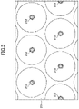
- FIG. 3 is a diagram showing an example of the structure of a charging portion 210 (charging electrodes 212 and 214). Specifically, FIG. 3 is a front view of the charging electrodes 212 and 214 viewed along the direction of a flow.
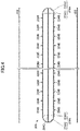
- FIGS. 4 and 5 show an example of the structure of a collection portion 220 (collection electrodes 222 and 224). Specifically, FIG. 4 is a longitudinal cross-sectional view of the collection electrodes 222 and 224 having the direction of a flow of the exhaust gas as a reference. FIG. 4 is a diagram depicting the collection electrode 224 viewed from the collection electrode 222 opposite to the collection electrode 224.
- the electrostatic precipitator 200 includes the charging portion 210, the collection portion 220, and a controller 230.
- the charging portion 210 includes the charging electrodes 212 and 214 and a DC power supply 216.
- the charging electrodes 212 and 214 are arranged opposite to each other, and generate a corona discharge therebetween according to a voltage applied by the DC power supply 216. This allows the particulate matter passing through the charging portion 210 to be electrified (charged).
- the charging electrodes 212 and 214 may be formed of an electrically conductive material such as stainless steel, tungsten, titanium, or carbon material. Hereinafter, the same may apply to the collection electrodes 222 and 224 described later.
- the DC power supply 216 applies a voltage to generate a corona discharge between the charging electrodes 212 and 214.
- the positive electrode of the DC power supply 216 is connected to the charging electrode 214 and grounded, and the negative electrode of the DC power supply 216 is connected to the charging electrode 212.
- a negative voltage is applied between the charging electrodes 212 and 214 such that the charging electrode 214 is set to the reference potential (ground potential) and the charging electrode 212 is set to a negative high potential.
- a corona discharge is generated from the charging electrode 212, and thereby the particulate matter of the exhaust gas passing between the charging electrodes 212 and 214 is negatively charged.
- the negative electrode of DC power supply 216 may be, on the other hand, connected to the charging electrode 214 and grounded, and the positive electrode of the DC power supply 216 may be connected to the charging electrode 212.
- a positive voltage is applied between the charging electrodes 212 and 214 such that the charging electrode 214 is set to the reference potential and the charging electrode 212 is set to a positive high potential.
- a corona discharge is generated from the charging electrode 212, and thereby the particulate matter of the exhaust gas passing between the charging electrodes 212 and 214 is positively charged.
- the charging electrodes 212 and 214 may be configured as a pair of a discharging electrode and a counter electrode of a cylindrical coaxial system (hereinafter, referred to as a "cylindrical coaxial electrode pair"), for example, as shown in FIGS. 2 and 3 .
- the charging electrode 214 as the counter electrode may have a substantially cylindrical inner peripheral surface extending along the direction of the flow of the exhaust gas
- the charging electrode 212 as the discharge electrode may have an elongated shape so as to extend along the central axis of the inner peripheral surface of the charging electrode 214.
- the term "substantially” is intended, for example, to allow manufacturing errors, and will be used hereinafter in the same sense.
- a distance (gap length) between the charging electrode 214 of the reference potential side and the charging electrode 212 of the high voltage side is substantially uniform at any position. Therefore, it is possible to avoid transition to a spark discharge and form a stable corona discharge.
- the charging electrode 212 and the charging electrode 214 are provided to extend in the direction of the flow of the exhaust gas, so that a pressure loss in the charging portion 210 can be reduced.
- the charging electrode 214 has a plurality of substantially cylindrical inner peripheral surfaces arranged in parallel with respect to the direction of the flow of the exhaust gas, each having a corresponding charging electrode 212 interposed therein, so that a plurality of cylindrical coaxial electrode pairs are configured.
- the stable corona discharge is realized, and a flow area of the exhaust gas is secured while a dimension in the flow direction of the exhaust gas of the charging portion 210 is maintained, so that the pressure loss can be further reduced and the flow rate of the exhaust gas can be made relatively larger.
- the collection portion 220 is disposed adjacent to the charging portion 210 on the downstream side of the flow of the exhaust gas.
- the collection portion 220 includes the collection electrodes 222 and 224, and a DC power supply 226.
- the collection electrodes 222 and 224 are arranged opposite to each other, and a voltage is applied therebetween by the DC power supply 226 to exert a Coulomb force on the particulate matter in the exhaust gas charged by the charging portion 210 and collect the particulate matter onto the collection electrode 224.
- the DC power supply 226 applies a voltage between the collection electrodes 222 and 224, to generate an electric field between the collection electrodes 222 and 224.
- the DC power supply 226 is provided separately from the DC power supply 216 which applies a voltage to the charging portion 210 (charging electrodes 212 and 214).
- the DC power supply 226 can vary the voltage applied to the collection portion 220 (collection electrodes 222 and 224) independently of the voltage applied to the charging portion 210.
- the positive electrode of the DC power supply 226 is connected to the collection electrode 224 and grounded, and the negative electrode of the DC power supply 226 is connected to the collection electrode 222.
- a negative voltage is applied between the collection electrodes 222 and 224 such that the collection electrode 224 is set to the reference potential (ground potential) and the collection electrode 222 is set to a negative high potential. Therefore, when the particulate matter negatively charged in the charging portion 210 enters between the collection electrodes 222 and 224, a Coulomb force drawn into the collection electrode 224 having the reference potential acts on the particulate matter, and the particulate matter is collected into the collection electrode 224.
- the positive electrode of the DC power supply 226 may be connected to the collection electrode 224, and the negative electrode thereof may be connected to the collection electrode 222 and grounded.
- a positive voltage is applied between the collection electrodes 222 and 224 such that the collection electrode 222 is set to the reference potential (ground potential) and the collection electrode 224 is set to a positive high potential. Therefore, when the particulate matter negatively charged in the charging portion 210 enters between the collection electrodes 222 and 224, a Coulomb force drawn into the collection electrode 224 having the positive high potential acts on the particulate matter, and the particulate matter is collected into the collection electrode 224.
- the DC power supply 226 may apply a voltage between the collection electrodes 222 and 224 such that an electric field from the collection electrode 224 to the collection electrode 222 is applied.
- the DC power supply 226 may apply a voltage between the collection electrodes 222 and 224 such that an electric field from the collection electrode 222 to the collection electrode 224 is applied.
- the positive electrode of the DC power supply 226 may be connected to the collection electrode 222, the negative electrode of the DC power supply 226 may be connected to the collection electrode 224, and either of them may be grounded.
- the collection electrode 222 may have a shape of a flat plate extending along the direction of the flow of the exhaust gas, for example, as shown in FIGS. 2 and 4 .
- the collection electrode 224 is configured to enclose a hollow space (in other words, have a shape of a hollow box) as shown in FIGS. 2 , 4 , and 5 , for example, and a through-hole 224B for opening the hollow space is provided in a part facing the collection electrode 222.
- the collection electrode 224 includes a main body portion 224A, the through-hole 224B, and a partition plate 224C. Further, both end portions of the collection electrode 224 in the depth direction of FIG. 4 are closed by a flat plate or the like.
- the main body portion 224A includes two flat plate portions 224A1 opposite to the two collection electrodes 222, respectively, and curved surface portions 224A2 at the both end portions connecting the two flat plate portions 224A1.
- the hollow space surrounded by the two flat plate portions 224A1 and the curved surface portions 224A2 at the both ends thereof is formed.
- the through-hole 224B (an example of an opening) is provided in the flat plate portion 224A1 in a manner of penetrating the flat plate portion 224A1. Specifically, as illustrated in FIGS. 4 and 5 , a lot of through-holes 224B are provided in a manner of occupying a very small area with respect to the area of the flat plate portion 224A1. Thus, the through-holes 224B open the hollow space inside the main body portion 224A to communicate the space between the collection electrodes 222 and 224 with the space inside the collection electrode 224 (main body portion 224A).
- the particulate matter in the exhaust gas that is drawn into the collection electrode 224 by a Coulomb force can be housed in the hollow space inside the collection electrode 224 (main body portion 224A). Therefore, it is possible to suppress re-scattering of the particulate matter collected by the collection electrode 224.
- the exhaust gas discharged from the main engine 100 of a ship has a relatively high flow rate, for example, the probability of re-scattering is relatively high in the case where the collection electrode has a shape of flat plate.
- the collection electrode 224 can suppress the re-scattering of the collected particulate matter even when the flow rate is relatively high, as is the case for the exhaust gas of the main engine 100 of the ship.
- the partition plate 224C is configured to partition the hollow space inside the main body portion 224A into a space on one side of the flat plate portion 224A1 and a space on the other side of the flat plate portion 224A1.
- the particulate matter flowing into the hollow space inside the main body portion 224A from the through-hole 224B of both flat plate portions 224A1 can be collected in a manner of adhering to both surfaces of the partition plate 224C. Therefore, in the hollow space where the flow speed is relatively lower than that of the main stream of exhaust gas, the particulate matter can be stably collected by fixing the particulate matter.
- a functional portion for charging the particulate matter of the exhaust gas and a functional portion for collecting the particulate matter are separated in the direction of the flow of the exhaust gas, and a pair of electrodes (charging electrodes 212 and 214 and collection electrodes 222 and 224) are provided for each functional portion.
- the function of the charging portion 210 and the function of the collection portion 220 may be integrated by arranging a discharging electrode, which generates a corona discharge, and the collection electrode, which collects the particulate matter charged by the corona discharge, opposite to each other, and applying a voltage between the discharging electrode and the collection electrode.
- the particulate matter charged by the discharge is likely to be concentrated on the downstream side of the flow of the exhaust gas at the collection electrode, which is actually collected, because the particulate matter moves in the flow of the exhaust gas.
- the upstream portion of the flow of the exhaust gas in the collection electrode may not perform the function of collecting the particulate matter and the discharge electrode may become unnecessarily long up to the downstream side of the flow of the exhaust gas due to the necessity of matching the length of the collection electrode.
- the length (size) of the collection electrode and the discharge electrode may be excessive. Therefore, the size of the electrostatic precipitator 200 may become larger.
- the function of charging the particulate matter of the exhaust gas and the function of collecting the charged particulate matter are separated in the direction of the flow of the exhaust gas, and the sizes can be optimized for their function, respectively. Therefore, it is possible to reduce the size of the electrostatic precipitator 200. In particular, it is suitable for the case where there is a limited space for the arrangement of the electrostatic precipitator 200, such as a ship.
- the controller 230 controls the DC power supply 226.
- the controller 230 is implemented as a function of any hardware or any combination of hardware and software.
- the controller 230 is configured mainly by a computer including a memory device such as a CPU (Central Processing Unit), a RAM (Random Access Memory), a non-volatile auxiliary storage device such as a ROM (Read Only Memory), an input/output (I/O) interface device, and the like.
- Various signals used for controlling the DC power supply 226 are input to the controller 230.
- a signal corresponding to a measured value of a temperature (exhaust gas temperature) of the exhaust gas flowing into the electrostatic precipitator 200 from a temperature sensor located near the inlet of the exhaust gas of the electrostatic precipitator 200 may be input to the controller 230.
- a signal relating to a load factor (engine load factor) of the main engine 100 may be input to the controller 230 from another controller which controls the main engine 100.
- the controller 230 may be input with a signal corresponding to a measured value of a temperature (engine temperature) of a predetermined portion of the main engine 100 from a temperature sensor installed in the predetermined portion of the main engine 100 (e.g., an exhaust manifold).
- the controller 230 may be input with a signal corresponding to a measured value of a temperature (precipitator temperature) of a predetermined portion of the electrostatic precipitator 200 from a temperature sensor installed in the predetermined portion of the electrostatic precipitator 200 (e.g., a housing of the electrostatic precipitator 200A).
- the controller 230 may be input with a signal corresponding to a measured value of a temperature of an exhaust pipe (exhaust pipe temperature) from a temperature sensor installed in the exhaust pipe between the main engine 100 and the electrostatic precipitator 200.
- FIG. 6 is a diagram illustrating a method of controlling the voltage applied to the collection portion 220 (collection electrodes 222 and 224). Specifically, FIG. 6 includes a graph 610 showing a relationship between the temperature of the gas (in the present embodiment, the exhaust gas) to be precipitated and the resistivity of the particulate matter (PM), and a graph 620 showing a relationship between the temperature of the gas (exhaust gas) to be precipitated and the voltage applied to the collection portion 220.
- the gas in the present embodiment, the exhaust gas
- PM resistivity of the particulate matter
- the resistivity (i.e., conductivity) of the particulate matter varies according to the temperature state of the exhaust gas.
- the particulate matter acts as a dielectric when the resistivity increases and the insulation becomes relatively high, and dielectric polarization can occur in the particulate matter collected and deposited on the collection electrode 224.
- a particulate matter with a relatively high resistivity may have a potential difference of a polarity opposite to the potential difference of the collection portion 220 due to the dielectric polarization.
- the potential difference is also relatively large, and as a result, a back discharge occurs and the particulate matter may scatter.
- the controller 230 controls the DC power supply 226 to make the voltage applied to the collection portion 220 relatively large (high) when the resistivity of the particulate matter is relatively low (i.e., a relatively high conductivity) and the possibility of the occurrence of the back discharge is relatively low.
- the controller 230 makes the voltage applied to the collection portion 220 relatively small (low) when the resistivity of the particulate matter is relatively high (i.e., a relatively low conductivity) and the possibility of the occurrence of the back discharge is relatively high.
- the controller 230 can suppress the re-scattering of the particulate matter due to the back discharge under the assumption that a relatively high electric field is applied to collect the particulate matter.
- the controller 230 may switch the voltage applied between the collection electrodes 222 and 224 of the collection portion 220 according to the temperature states of the exhaust gas flowing into the electrostatic precipitator 200. Specifically, the controller 230 may control the DC power supply 226 by setting the voltage applied between the collection electrodes 222 and 224 to a predetermined value Va_H which is relatively high, when the temperature of the exhaust gas flowing into the electrostatic precipitator 200 is lower than 100°C or higher than 200°C.
- the controller 230 may control the DC power supply 226 by setting the voltage applied between the collection electrodes 222 and 224 to a predetermined value Va_L which is relatively low, when the temperature of the exhaust gas flowing into the electrostatic precipitator 200 is in a range of from 100°C to 200°C inclusive.
- Va_L a predetermined value which is relatively low
- the controller 230 makes relatively lower the voltage applied between the collection electrodes 222 and 224 in the temperature range of the exhaust gas in which the back discharge is likely to occur, thereby suppressing the re-scattering of the collected particulate matter.
- the temperature state of the exhaust gas flowing into the electrostatic precipitator 200 is measured by the temperature sensor positioned near the inlet of the electrostatic precipitator 200, for example, as described above, and a signal corresponding to the measured value may be input to the controller 230.
- the controller 230 may also estimate the temperature of the exhaust gas flowing into the electrostatic precipitator 200 based on, for example, the temperature (measurement) of the exhaust gas measured by a temperature sensor installed further upstream from the inlet of the electrostatic precipitator 200.
- the controller 230 may also estimate the temperature of the exhaust gas flowing into the electrostatic precipitator 200 from other information as described below.
- the controller 230 may switch the voltage applied between the collection electrodes 222 and 224 of the collection portion 220 according to the state of the main engine 100 (an example of a supply source of gas) associated with the temperature of the exhaust gas.
- the controller 230 may, for example, switch the voltage applied between the collection electrodes 222 and 224 of the collection portion 220 according to the load state (e.g., engine load factor) of the main engine 100. This is because, as shown in FIG. 6 , when the load of the main engine 100 is relatively small, the temperature of the exhaust gas decreases, and when the load of the main engine 100 is relatively high, the temperature of the exhaust gas becomes relatively high.
- the load state e.g., engine load factor
- the controller 230 may set the voltage applied between the collection electrodes 222 and 224 to a predetermined value Va_H. Meanwhile, when the load factor of the main engine 100 is in a range of from the predetermined value LF1 to the predetermined value LF2 inclusive, the controller 230 may set the voltage applied between the collection electrodes 222 and 224 to a predetermined value Va_L.
- the predetermined values LF1 and LF2 correspond to the load factors of the main engine 100 when the temperature of the exhaust gas flowing into the electrostatic precipitator 200 is 100°C and 200°C, respectively.
- the load factor information of the main engine 100 may be obtained from the other controller controlling the main engine 100 as described above. Further, data on an operation status of the main engine 100 may be acquired from the other controller by the controller 230, and the controller 230 may calculate the load factor of the main engine 100 from the data on the acquired operation status.
- the controller 230 may switch the voltage applied between the collection electrodes 222 and 224 of the collection portion 220 according to, for example, the temperature state of the predetermined portion of the main engine 100. This is because when the temperature of the exhaust gas of the main engine 100 is relatively low, the temperature of the main engine 100 itself is relatively low, and when the temperature of the exhaust gas of the main engine 100 is relatively high, the temperature of the main engine 100 itself is relatively high.
- the controller 230 may set the voltage applied between the collection electrodes 222 and 224 to a predetermined value Va_H. Meanwhile, the controller 230 may set the voltage applied between the collection electrodes 222 and 224 to a predetermined value Va_L when the temperature of the predetermined portion of the main engine 100 is in a range of from the predetermined value ET1 to the predetermined value ET2 inclusive.
- the predetermined values ET1 and ET2 correspond to the temperatures at the predetermined portion of the main engine 100 when the temperature of the exhaust gas flowing into the electrostatic precipitator 200 is 100°C and 200°C, respectively.
- the temperature of the predetermined portion of the main engine 100 is measured by the temperature sensor installed in the main engine 100 as described above, and a signal corresponding to the measured value may be input to the controller 230.
- the controller 230 may estimate the temperature of the exhaust gas flowing into the electrostatic precipitator 200 based on the load factor of the main engine 100, the temperature state of the predetermined portion, or the like.
- the controller 230 may switch the voltage applied between the collection electrodes 222 and 224 of the collection portion 220 in the same manner as described above according to the estimated value of the temperature of the exhaust gas flowing into the electrostatic precipitator 200.
- the controller 230 may switch the voltage applied between the collection electrodes 222 and 224 of the collection portion 220 according to the temperature (exhaust pipe temperature) of a predetermined portion of the exhaust pipe (an example of a gas supply path) between the main engine 100 and the electrostatic precipitator 200.
- the controller 230 may switch the voltage applied between the collection electrodes 222 and 224 of the collection portion 220 according to the temperature (precipitator temperature) of a predetermined portion of the electrostatic precipitator 200. This is because when the temperature of the exhaust gas of the main engine 100 is relatively low, the temperature of the exhaust pipe and the electrostatic precipitator 200 is relatively low, and when the temperature of the exhaust gas of the main engine 100 is relatively high, the temperature of the exhaust pipe and the electrostatic precipitator 200 is relatively high.
- the controller 230 may set the voltage applied between the collection electrodes 222 and 224 to a predetermined value Va_H. Meanwhile, the controller 230 may set the voltage applied between the collection electrodes 222 and 224 to a predetermined value Va_L when the exhaust pipe temperature is within a range of from the predetermined value XT1 to a predetermined value XT2 inclusive.
- the predetermined values XT1 and XT2 correspond to the exhaust pipe temperatures when the temperature of the exhaust gas flowing into the electrostatic precipitator 200 is 100°C and 200°C, respectively. The same method may be employed when controlled according to the precipitator temperature.
- the controller 230 may estimate the temperature of the exhaust gas flowing into the electrostatic precipitator 200 based on the temperature of the exhaust pipe, the precipitator temperature, or the like.
- the controller 230 may switch the voltage applied between the collection electrodes 222 and 224 of the collection portion 220 in the same manner as described above according to the estimated value of the temperature of the exhaust gas flowing into the electrostatic precipitator 200.
- electrostatic precipitator 200 may be changed or modified as appropriate.
- a single through-hole 224B of the collection electrode 224 may be provided in the flat plate portion 224A1 facing the collection electrode 222.
- the lower limit of the temperature range of the exhaust gas which makes the voltage applied between the collection electrodes 222 and 224 relatively low may be set within a predetermined range before and after 100°C instead of at 100°C.
- This predetermined range may, for example, exceed or be less than 100°C by 10°C, i.e., in the range of from 90°C to 110°C.
- the upper limit of the temperature range of the exhaust gas which makes the voltage applied between the collection electrodes 222 and 224 relatively low may be set within a predetermined range before and after 200°C instead of at 200°C.
- This predetermined range may, for example, exceed or less than 200°C by 10°C, i.e., the range of from 190°C to 210°C.
- the boundary value of the temperature of the exhaust gas for switching the voltage applied between the collection electrodes 222 and 224 from the relatively high state to the relatively low state may be different from the boundary value for switching from the relatively low state to the relatively high state.
- the controller 230 may switch the voltage applied between the collection electrodes 222 and 224 from the relatively high state to the relatively low state when the temperature of the exhaust gas becomes 100°C or higher from a state of lower than 100°C.
- the controller 230 may switch the voltage applied between the collection electrodes 222 and 224 from the relatively low state to the high state when the temperature of the exhaust gas becomes lower than a predetermined temperature, which is lower than 100°C (for example, 95°C), from a state of the predetermined temperature or higher. Similarly, the controller 230 may switch the voltage applied between the collection electrodes 222 and 224 from a relatively high state to a relatively low state when the temperature of the exhaust gas becomes 200°C or lower from a state of higher than 200°C.
- a predetermined temperature which is lower than 100°C (for example, 95°C)
- the controller 230 may switch the voltage applied between the collection electrodes 222 and 224 from a relatively high state to a relatively low state when the temperature of the exhaust gas becomes 200°C or lower from a state of higher than 200°C.
- the controller 230 may switch the voltage applied between the collection electrodes 222 and 224 from a relatively low state to a relatively high state when the temperature of the exhaust gas becomes higher than a predetermined temperature, which is higher than 200°C (for example, 205°C), from a state of the predetermined temperature or lower.
- a predetermined temperature which is higher than 200°C (for example, 205°C)
- the above-described example of the electrostatic precipitator 200 may collect particulate matter from an exhaust gas emitted from an engine located at a different location from the ship.
- the above-described example of the electrostatic precipitator 200 may collect particulate matter contained in a gas different from the engine exhaust gas.
- the electrostatic precipitator 200 includes a charging portion 210 and a collection portion 220.
- the charging portion 210 includes charging electrodes 212 and 214, opposite to each other, a voltage being applied between the charging electrodes 212 and 214, and charges particulate matter in a gas (e.g., exhaust gas) passing between the charging electrodes by generating a corona discharge.
- the collection portion 220 includes collection electrodes 222 and 224, opposite to each other, a voltage being applied between the collection electrodes 222 and 224, and collects by a Coulomb force the particulate matter charged by the charging portion 210.
- one collection electrode 224 of the collection electrodes 222 and 224 is configured to surround a hollow space, and a through-hole 224B for opening the hollow space is provided at a part of the collection electrode 224 facing the other collection electrode 222.
- the function of charging particulate matter in the passing gas can be separated from the function of collecting charged particulate matter in the direction of the flow of the gas. Therefore, the size of the electrostatic precipitator 200 can be optimized for each function, thereby reducing the size of the electrostatic precipitator 200.
- the collection electrode 224 by causing the collection electrode 224 to attract the particulate matter charged by a Coulomb force, the particulate matter is collected in the hollow space inside the through-hole 224B of the collection electrode 224. Therefore, even when the flow speed of the gas is relatively high, it is not affected by the flow speed and re-scattering can be suppressed. Thus, particulate matter in the gas can be collected more efficiently.
- a voltage may be applied between the collection electrodes 222 and 224 such that the one collection electrode 224 has the reference potential and the other collection electrode 222 has the polarity that is the same as the charging electrode 212 with the higher potential of the charging electrodes 212 and 214.
- a voltage may also be applied between the collection electrodes 222 and 224 so that the other collection electrode 222 has the reference potential and the polarity of the one collection electrode 224 is opposite to the charging electrode 212 with the higher potential.
- the electrostatic precipitator 200 can apply an electric field between the collection electrodes 222 and 224 such that the particulate matter charged by the charging portion 210 is collected by the collection electrode 224.
- the other collection electrode 222 has a flat plate shape
- the one collection electrode 224 has a flat plate portion 224A1 facing the other collection electrode 222
- the flat plate portion 224A1 may be provided with a plurality of through-holes 224B for opening the hollow space.
- the electrostatic precipitator 200 can collect the particulate matter charged by the charging portion 210 in the hollow space inside the collection electrode 224 through the plurality of through-holes 224B.
- the charging portion 210 may also include the DC power supply 216 that applies a voltage to the charging electrodes 212 and 214.
- the collection portion 220 may then include the DC power supply 226, which applies a voltage to the collection electrodes 222 and 224, that is different from the DC power supply 216.
- the electrostatic precipitator 200 can vary the voltage applied to the collection portion 220 independently of the voltage applied to the charging portion 210.
- the electrostatic precipitator 200 may vary the magnitude of the voltage applied between the collection electrodes 222 and 224 according to a temperature state of a passing gas.
- the conductivity (resistivity) of a particulate matter varies with the temperature state of the passing gas. Then, when the conductivity decreases (i.e., the resistivity increases), the collected and deposited particulate matter may have a high inverse potential to the potential of the collection electrode 224 due to a dielectric polarization, and as a result, a back discharge may occur and the particulate matter may re-scatter.
- the electrostatic precipitator 200 can vary the magnitude of the voltage applied to the collection portion 220 according to the temperature state of the gas that affects the conductivity of the particulate matter.
- the electrostatic precipitator 200 can make the applied voltage relatively small to lower an electric field required for charge-up under a state where the conductivity of the particulate matter is reduced and a back discharge is highly likely to occur. Therefore, the electrostatic precipitator 200 can suppress the re-scattering of the particulate matter due to the back discharge.
- the electrostatic precipitator 200 may vary the magnitude of the voltage applied between the collection electrodes 222 and 224 according to the state of the gas supply source associated with the temperature state of the passing gas.
- the electrostatic precipitator 200 may vary the magnitude of the voltage applied between the collection electrodes 222 and 224 according to the load state of the main engine 100 or the temperature state of a predetermined portion of the main engine 100.
- the electrostatic precipitator 200 can adjust the applied voltage based on the relationship between the state of the gas supply and the temperature state of the passing gas, in consideration of the conductivity of the particulate matter. Therefore, the electrostatic precipitator 200 can specifically suppress the re-scattering of the particulate matter due to the back discharge.
- the electrostatic precipitator 200 may vary the magnitude of the voltage applied between the collection electrodes 222 and 224 according to at least one of the temperature state of the supply path (e.g., exhaust pipe) of the passing gas and the temperature state of a predetermined portion of the electrostatic precipitator 200.
- the temperature state of the supply path e.g., exhaust pipe
- the electrostatic precipitator 200 can adjust the applied voltage, based on the relationship between the temperature state of the supply path of the gas or the predetermined portion of the electrostatic precipitator 200 and the temperature state of the passing gas, in consideration of the conductivity of the particulate matter. Therefore, the electrostatic precipitator 200 can specifically suppress the re-scattering of the particulate matter due to the back discharge.
- the electrostatic precipitator 200 when the temperature of the passing gas is within the predetermined temperature range, the electrostatic precipitator 200 (controller 230) makes a magnitude of voltage applied between the two collection electrodes smaller than the case where the temperature is outside the predetermined temperature range.
- the predetermined temperature range is, for example, a range between a lower limit specified in a predetermined range before and after 100°C and an upper limit specified in a predetermined range before and after 200°C.
- the electrostatic precipitator 200 can specifically reduce (lower) the electric field applied between the collection electrodes 222 and 224 in the area where the back discharge is likely to occur.
- the charging electrode 214 having a reference potential of the two charging electrodes 212 and 214 may have a substantially cylindrical inner peripheral surface extending in the direction of the flow of the gas.
- the charging electrode 212 with the higher potential of the charging electrodes 212 and 214 may be disposed to extend in the direction of the flow of the gas substantially coaxially with the inner peripheral surface of the charging electrode 214.
- the pressure loss of the gas passing through the charging portion 210 can be suppressed.
- the distances (gap lengths) to the charging electrode 214 on the reference potential side are substantially uniform at any position of the charging electrode 214 on the high voltage side, it is possible to avoid the transition to the spark discharge and form a stable corona discharge.
Landscapes
- Engineering & Computer Science (AREA)
- Chemical & Material Sciences (AREA)
- Combustion & Propulsion (AREA)
- Mechanical Engineering (AREA)
- General Engineering & Computer Science (AREA)
- Automation & Control Theory (AREA)
- Ocean & Marine Engineering (AREA)
- Electrostatic Separation (AREA)
- Processes For Solid Components From Exhaust (AREA)
Abstract
Description
- The present disclosure relates to an electrostatic precipitator.
- For example, an electrostatic precipitator having a charging portion for charging a particulate matter (PM) contained in a gas; and a precipitation portion (collection portion) disposed adjacent to a downstream side of the charging portion in which charged particulate matter is collected by a Coulomb force has been known (see Patent Document 1).
- Patent Document 1:
Japanese Unexamined Patent Application Publication No. 2018-126714 - However, in
Patent Document 1, an electrode of the collection portion for applying an electric field to the charged particulate matter has a flat shape. Therefore, depending on a speed of a flow of the gas, the particulate matter collected on a surface thereof may re-scatter. - Therefore, the present disclosure aims at providing a technology capable of more efficiently collecting a particulate matter in view of the above-described problem.
- In order to accomplish the above-described purpose, according to an aspect of the present disclosure,
- an electrostatic precipitator including
- a charging portion including two charging electrodes opposite to each other, the charging portion being configured to charge a particulate matter in a gas passing between the two charging electrodes by applying a first voltage between the two charging electrodes to generate a corona discharge; and
- a collection portion including two collection electrodes opposite to each other, the collection portion being configured to collect by a Coulomb force the particulate matter charged by the charging portion by applying a second voltage between the two collection electrodes,
- one collection electrode of the two collection electrodes surrounding a hollow space, and an opening to open the hollow space being formed in a part of the one collection electrode facing the other collection electrode,
is provided. - In accordance with the above-described embodiments, particulate matter can be collected more efficiently.
-
- [
FIGURE 1] FIG. 1 is a diagram depicting an example of an exhaust gas purification system including an electrostatic precipitator. - [
FIGURE 2] FIG. 2 is a diagram depicting an example of the electrostatic precipitator. - [
FIGURE 3] FIG. 3 is a diagram depicting an example of a structure of a charging electrode. - [
FIGURE 4] FIG. 4 is a diagram depicting an example of a structure of a collection electrode. - [
FIGURE 5] FIG. 5 is a diagram depicting another example of the structure of the collection electrode. - [
FIGURE 6] FIG. 6 is a diagram illustrating a method of controlling a voltage applied to the collection portion. - Hereinafter, embodiments will be described with reference to the drawings.
- First, an exhaust
gas purification system 1 including anelectrostatic precipitator 200 according to the present embodiment will be described with reference toFIG. 1 . -
FIG. 1 is a diagram illustrating an example of the exhaustgas purification system 1 including theelectrostatic precipitator 200 according to the present embodiment. - The exhaust
gas purification system 1 is loaded in a ship. Hereinafter, "ship" means, unless otherwise specified, a ship in which anelectrostatic precipitator 200 is loaded. - As shown in
FIG. 1 , the exhaustgas purification system 1 includes amain engine 100, theelectrostatic precipitator 200, ascrubber 300, and apump 400. The exhaustgas purification system 1 purifies an exhaust gas emitted from themain engine 100 and discharges an exhaust gas from a chimney of the ship to the outside. - The main engine 100 (an example of an engine) rotates a propeller to propel the ship. The main engine is, for example, a diesel engine capable of using heavy oil C as a fuel.
- The
electrostatic precipitator 200 collects particulate matter (PM) contained in the exhaust gas (an example of gas) of themain engine 100. Exhaust gas collected by the electrostatic precipitator 200 (particulate matter is removed) is fed to thescrubber 300. - The
scrubber 300 sprays seawater supplied through thepump 400 into the exhaust gas of themain engine 100 passing therethrough to absorb sulfur oxide (SOx) contained in themain engine 100 into the seawater. The seawater supplied to thescrubber 300 may be seawater that is constantly pumped out of the sea using an open loop system or seawater that is neutralized and circulated (reused) in a neutralization tank using a closed loop system. The exhaust gas from thescrubber 300 from which SOx components have been removed is released into the atmosphere outside the ship through the chimney of the ship. Seawater that absorbs the SOx components of the exhaust gas discharged from thescrubber 300 is discharged into the sea outside the ship using the open loop system or is returned to the neutralization tank using the closed loop system for reuse. - The
pump 400 pumps seawater into thescrubber 300 from the sea or from the neutralization tank. - Thus, the exhaust
gas purification system 1 can purify the exhaust gas of themain engine 100 using theelectrostatic precipitator 200 and thescrubber 300. - Next, an example of the
electrostatic precipitator 200 will be described with reference toFIGS. 2 to 6 . -
FIG. 2 is a diagram illustrating an example of anelectrostatic precipitator 200 in accordance with the present embodiment.FIG. 3 is a diagram showing an example of the structure of a charging portion 210 (charging electrodes 212 and 214). Specifically,FIG. 3 is a front view of thecharging electrodes FIGS. 4 and5 show an example of the structure of a collection portion 220 (collection electrodes 222 and 224). Specifically,FIG. 4 is a longitudinal cross-sectional view of thecollection electrodes FIG. 4 is a diagram depicting thecollection electrode 224 viewed from thecollection electrode 222 opposite to thecollection electrode 224. - As shown in
FIG. 2 , theelectrostatic precipitator 200 includes thecharging portion 210, thecollection portion 220, and acontroller 230. - The
charging portion 210 includes thecharging electrodes DC power supply 216. - The
charging electrodes DC power supply 216. This allows the particulate matter passing through thecharging portion 210 to be electrified (charged). Thecharging electrodes collection electrodes - The DC power supply 216 (an example of the first power supply) applies a voltage to generate a corona discharge between the
charging electrodes DC power supply 216 is connected to thecharging electrode 214 and grounded, and the negative electrode of theDC power supply 216 is connected to thecharging electrode 212. Thus, a negative voltage is applied between thecharging electrodes charging electrode 214 is set to the reference potential (ground potential) and thecharging electrode 212 is set to a negative high potential. Then, a corona discharge is generated from thecharging electrode 212, and thereby the particulate matter of the exhaust gas passing between thecharging electrodes - The negative electrode of
DC power supply 216 may be, on the other hand, connected to thecharging electrode 214 and grounded, and the positive electrode of theDC power supply 216 may be connected to thecharging electrode 212. In this case, a positive voltage is applied between the chargingelectrodes electrode 214 is set to the reference potential and the chargingelectrode 212 is set to a positive high potential. Then, a corona discharge is generated from the chargingelectrode 212, and thereby the particulate matter of the exhaust gas passing between the chargingelectrodes - The charging
electrodes FIGS. 2 and3 . Specifically, the chargingelectrode 214 as the counter electrode may have a substantially cylindrical inner peripheral surface extending along the direction of the flow of the exhaust gas, and the chargingelectrode 212 as the discharge electrode may have an elongated shape so as to extend along the central axis of the inner peripheral surface of the chargingelectrode 214. The term "substantially" is intended, for example, to allow manufacturing errors, and will be used hereinafter in the same sense. Thus, a distance (gap length) between the chargingelectrode 214 of the reference potential side and the chargingelectrode 212 of the high voltage side is substantially uniform at any position. Therefore, it is possible to avoid transition to a spark discharge and form a stable corona discharge. The chargingelectrode 212 and the charging electrode 214 (inner peripheral surface) are provided to extend in the direction of the flow of the exhaust gas, so that a pressure loss in the chargingportion 210 can be reduced. - Also, as shown in
FIG. 3 , the chargingelectrode 214 has a plurality of substantially cylindrical inner peripheral surfaces arranged in parallel with respect to the direction of the flow of the exhaust gas, each having acorresponding charging electrode 212 interposed therein, so that a plurality of cylindrical coaxial electrode pairs are configured. Thus, the stable corona discharge is realized, and a flow area of the exhaust gas is secured while a dimension in the flow direction of the exhaust gas of the chargingportion 210 is maintained, so that the pressure loss can be further reduced and the flow rate of the exhaust gas can be made relatively larger. - The
collection portion 220 is disposed adjacent to the chargingportion 210 on the downstream side of the flow of the exhaust gas. Thecollection portion 220 includes thecollection electrodes DC power supply 226. - The
collection electrodes DC power supply 226 to exert a Coulomb force on the particulate matter in the exhaust gas charged by the chargingportion 210 and collect the particulate matter onto thecollection electrode 224. - The DC power supply 226 (an example of a second power supply) applies a voltage between the
collection electrodes collection electrodes DC power supply 226 is provided separately from theDC power supply 216 which applies a voltage to the charging portion 210 (chargingelectrodes 212 and 214). Thus, theDC power supply 226 can vary the voltage applied to the collection portion 220 (collection electrodes 222 and 224) independently of the voltage applied to the chargingportion 210. Specifically, the positive electrode of theDC power supply 226 is connected to thecollection electrode 224 and grounded, and the negative electrode of theDC power supply 226 is connected to thecollection electrode 222. Thus, a negative voltage is applied between thecollection electrodes collection electrode 224 is set to the reference potential (ground potential) and thecollection electrode 222 is set to a negative high potential. Therefore, when the particulate matter negatively charged in the chargingportion 210 enters between thecollection electrodes collection electrode 224 having the reference potential acts on the particulate matter, and the particulate matter is collected into thecollection electrode 224. - The positive electrode of the
DC power supply 226 may be connected to thecollection electrode 224, and the negative electrode thereof may be connected to thecollection electrode 222 and grounded. Thus, a positive voltage is applied between thecollection electrodes collection electrode 222 is set to the reference potential (ground potential) and thecollection electrode 224 is set to a positive high potential. Therefore, when the particulate matter negatively charged in the chargingportion 210 enters between thecollection electrodes collection electrode 224 having the positive high potential acts on the particulate matter, and the particulate matter is collected into thecollection electrode 224. That is, when the particulate matter is negatively charged by the chargingportion 210, theDC power supply 226 may apply a voltage between thecollection electrodes collection electrode 224 to thecollection electrode 222 is applied. As described above, if the particulate matter is positively charged by the chargingportion 210, theDC power supply 226 may apply a voltage between thecollection electrodes collection electrode 222 to thecollection electrode 224 is applied. Thus, when the particulate matter positively charged in the chargingportion 210 enters between thecollection electrodes collection electrode 224. Specifically, if the particulate matter is positively charged by the chargingportion 210, the positive electrode of theDC power supply 226 may be connected to thecollection electrode 222, the negative electrode of theDC power supply 226 may be connected to thecollection electrode 224, and either of them may be grounded. - The
collection electrode 222 may have a shape of a flat plate extending along the direction of the flow of the exhaust gas, for example, as shown inFIGS. 2 and4 . - The
collection electrode 224 is configured to enclose a hollow space (in other words, have a shape of a hollow box) as shown inFIGS. 2 ,4 , and5 , for example, and a through-hole 224B for opening the hollow space is provided in a part facing thecollection electrode 222. Specifically, thecollection electrode 224 includes amain body portion 224A, the through-hole 224B, and apartition plate 224C. Further, both end portions of thecollection electrode 224 in the depth direction ofFIG. 4 are closed by a flat plate or the like. - The
main body portion 224A includes two flat plate portions 224A1 opposite to the twocollection electrodes 222, respectively, and curved surface portions 224A2 at the both end portions connecting the two flat plate portions 224A1. Thus, the hollow space surrounded by the two flat plate portions 224A1 and the curved surface portions 224A2 at the both ends thereof is formed. - The through-
hole 224B (an example of an opening) is provided in the flat plate portion 224A1 in a manner of penetrating the flat plate portion 224A1. Specifically, as illustrated inFIGS. 4 and5 , a lot of through-holes 224B are provided in a manner of occupying a very small area with respect to the area of the flat plate portion 224A1. Thus, the through-holes 224B open the hollow space inside themain body portion 224A to communicate the space between thecollection electrodes main body portion 224A). Therefore, the particulate matter in the exhaust gas that is drawn into thecollection electrode 224 by a Coulomb force can be housed in the hollow space inside the collection electrode 224 (main body portion 224A). Therefore, it is possible to suppress re-scattering of the particulate matter collected by thecollection electrode 224. In particular, since the exhaust gas discharged from themain engine 100 of a ship has a relatively high flow rate, for example, the probability of re-scattering is relatively high in the case where the collection electrode has a shape of flat plate. On the other hand, thecollection electrode 224 can suppress the re-scattering of the collected particulate matter even when the flow rate is relatively high, as is the case for the exhaust gas of themain engine 100 of the ship. - The
partition plate 224C is configured to partition the hollow space inside themain body portion 224A into a space on one side of the flat plate portion 224A1 and a space on the other side of the flat plate portion 224A1. Thus, the particulate matter flowing into the hollow space inside themain body portion 224A from the through-hole 224B of both flat plate portions 224A1 can be collected in a manner of adhering to both surfaces of thepartition plate 224C. Therefore, in the hollow space where the flow speed is relatively lower than that of the main stream of exhaust gas, the particulate matter can be stably collected by fixing the particulate matter. - Thus, in the example of the present disclosure, a functional portion (charging portion 210) for charging the particulate matter of the exhaust gas and a functional portion for collecting the particulate matter are separated in the direction of the flow of the exhaust gas, and a pair of electrodes (charging
electrodes collection electrodes 222 and 224) are provided for each functional portion. - For example, the function of the charging
portion 210 and the function of thecollection portion 220 may be integrated by arranging a discharging electrode, which generates a corona discharge, and the collection electrode, which collects the particulate matter charged by the corona discharge, opposite to each other, and applying a voltage between the discharging electrode and the collection electrode. However, in this case, the particulate matter charged by the discharge is likely to be concentrated on the downstream side of the flow of the exhaust gas at the collection electrode, which is actually collected, because the particulate matter moves in the flow of the exhaust gas. Therefore, the upstream portion of the flow of the exhaust gas in the collection electrode may not perform the function of collecting the particulate matter and the discharge electrode may become unnecessarily long up to the downstream side of the flow of the exhaust gas due to the necessity of matching the length of the collection electrode. In particular, since the flow speed of the exhaust gas of themain engine 100 of the ship is relatively high (large), the length (size) of the collection electrode and the discharge electrode may be excessive. Therefore, the size of theelectrostatic precipitator 200 may become larger. - In contrast, in the example of the present disclosure, the function of charging the particulate matter of the exhaust gas and the function of collecting the charged particulate matter are separated in the direction of the flow of the exhaust gas, and the sizes can be optimized for their function, respectively. Therefore, it is possible to reduce the size of the
electrostatic precipitator 200. In particular, it is suitable for the case where there is a limited space for the arrangement of theelectrostatic precipitator 200, such as a ship. - The
controller 230 controls theDC power supply 226. Thecontroller 230 is implemented as a function of any hardware or any combination of hardware and software. For example, thecontroller 230 is configured mainly by a computer including a memory device such as a CPU (Central Processing Unit), a RAM (Random Access Memory), a non-volatile auxiliary storage device such as a ROM (Read Only Memory), an input/output (I/O) interface device, and the like. - Various signals used for controlling the
DC power supply 226 are input to thecontroller 230. For example, a signal corresponding to a measured value of a temperature (exhaust gas temperature) of the exhaust gas flowing into theelectrostatic precipitator 200 from a temperature sensor located near the inlet of the exhaust gas of theelectrostatic precipitator 200 may be input to thecontroller 230. For example, a signal relating to a load factor (engine load factor) of themain engine 100 may be input to thecontroller 230 from another controller which controls themain engine 100. For example, thecontroller 230 may be input with a signal corresponding to a measured value of a temperature (engine temperature) of a predetermined portion of themain engine 100 from a temperature sensor installed in the predetermined portion of the main engine 100 (e.g., an exhaust manifold). For example, thecontroller 230 may be input with a signal corresponding to a measured value of a temperature (precipitator temperature) of a predetermined portion of theelectrostatic precipitator 200 from a temperature sensor installed in the predetermined portion of the electrostatic precipitator 200 (e.g., a housing of the electrostatic precipitator 200A). For example, thecontroller 230 may be input with a signal corresponding to a measured value of a temperature of an exhaust pipe (exhaust pipe temperature) from a temperature sensor installed in the exhaust pipe between themain engine 100 and theelectrostatic precipitator 200. -
FIG. 6 is a diagram illustrating a method of controlling the voltage applied to the collection portion 220 (collection electrodes 222 and 224). Specifically,FIG. 6 includes agraph 610 showing a relationship between the temperature of the gas (in the present embodiment, the exhaust gas) to be precipitated and the resistivity of the particulate matter (PM), and agraph 620 showing a relationship between the temperature of the gas (exhaust gas) to be precipitated and the voltage applied to thecollection portion 220. - As shown in the
graph 610, the resistivity (i.e., conductivity) of the particulate matter varies according to the temperature state of the exhaust gas. - The particulate matter acts as a dielectric when the resistivity increases and the insulation becomes relatively high, and dielectric polarization can occur in the particulate matter collected and deposited on the
collection electrode 224. Thus, a particulate matter with a relatively high resistivity may have a potential difference of a polarity opposite to the potential difference of thecollection portion 220 due to the dielectric polarization. Particularly, when the deposited layer of particulate matter is relatively thick, the potential difference is also relatively large, and as a result, a back discharge occurs and the particulate matter may scatter. - Specifically, it has been found that when the resistivity of the particulate matter increases to about 1011 [Ωcm], a back discharge is likely to occur. Therefore, as shown in the
graph 610, when the temperature of the particulate matter, i.e., the temperature of the exhaust gas, is in the range from about 100°C to about 200°C, and the resistivity of the particulate matter is greater than or equal to 1011 [Ωcm], the back discharge is likely to occur. - In contrast, in the example of the present disclosure, the
controller 230 controls theDC power supply 226 to make the voltage applied to thecollection portion 220 relatively large (high) when the resistivity of the particulate matter is relatively low (i.e., a relatively high conductivity) and the possibility of the occurrence of the back discharge is relatively low. On the other hand, thecontroller 230 makes the voltage applied to thecollection portion 220 relatively small (low) when the resistivity of the particulate matter is relatively high (i.e., a relatively low conductivity) and the possibility of the occurrence of the back discharge is relatively high. Thus, thecontroller 230 can suppress the re-scattering of the particulate matter due to the back discharge under the assumption that a relatively high electric field is applied to collect the particulate matter. - For example, as shown in the
graph 620, thecontroller 230 may switch the voltage applied between thecollection electrodes collection portion 220 according to the temperature states of the exhaust gas flowing into theelectrostatic precipitator 200. Specifically, thecontroller 230 may control theDC power supply 226 by setting the voltage applied between thecollection electrodes electrostatic precipitator 200 is lower than 100°C or higher than 200°C. On the other hand, thecontroller 230 may control theDC power supply 226 by setting the voltage applied between thecollection electrodes electrostatic precipitator 200 is in a range of from 100°C to 200°C inclusive. Thus, thecontroller 230 makes relatively lower the voltage applied between thecollection electrodes - The temperature state of the exhaust gas flowing into the
electrostatic precipitator 200 is measured by the temperature sensor positioned near the inlet of theelectrostatic precipitator 200, for example, as described above, and a signal corresponding to the measured value may be input to thecontroller 230. Thecontroller 230 may also estimate the temperature of the exhaust gas flowing into theelectrostatic precipitator 200 based on, for example, the temperature (measurement) of the exhaust gas measured by a temperature sensor installed further upstream from the inlet of theelectrostatic precipitator 200. Thecontroller 230 may also estimate the temperature of the exhaust gas flowing into theelectrostatic precipitator 200 from other information as described below. - For example, the
controller 230 may switch the voltage applied between thecollection electrodes collection portion 220 according to the state of the main engine 100 (an example of a supply source of gas) associated with the temperature of the exhaust gas. - The
controller 230 may, for example, switch the voltage applied between thecollection electrodes collection portion 220 according to the load state (e.g., engine load factor) of themain engine 100. This is because, as shown inFIG. 6 , when the load of themain engine 100 is relatively small, the temperature of the exhaust gas decreases, and when the load of themain engine 100 is relatively high, the temperature of the exhaust gas becomes relatively high. - Specifically, when the load factor of the
main engine 100 is lower than a predetermined value LF1 or higher than a predetermined value LF2 (>LF1), thecontroller 230 may set the voltage applied between thecollection electrodes main engine 100 is in a range of from the predetermined value LF1 to the predetermined value LF2 inclusive, thecontroller 230 may set the voltage applied between thecollection electrodes main engine 100 when the temperature of the exhaust gas flowing into theelectrostatic precipitator 200 is 100°C and 200°C, respectively. - The load factor information of the
main engine 100 may be obtained from the other controller controlling themain engine 100 as described above. Further, data on an operation status of themain engine 100 may be acquired from the other controller by thecontroller 230, and thecontroller 230 may calculate the load factor of themain engine 100 from the data on the acquired operation status. - The
controller 230 may switch the voltage applied between thecollection electrodes collection portion 220 according to, for example, the temperature state of the predetermined portion of themain engine 100. This is because when the temperature of the exhaust gas of themain engine 100 is relatively low, the temperature of themain engine 100 itself is relatively low, and when the temperature of the exhaust gas of themain engine 100 is relatively high, the temperature of themain engine 100 itself is relatively high. - Specifically, when the temperature of the predetermined portion of the
main engine 100 is lower than a predetermined value ET1 or higher than a predetermined value ET2 (>ET1), thecontroller 230 may set the voltage applied between thecollection electrodes controller 230 may set the voltage applied between thecollection electrodes main engine 100 is in a range of from the predetermined value ET1 to the predetermined value ET2 inclusive. The predetermined values ET1 and ET2 correspond to the temperatures at the predetermined portion of themain engine 100 when the temperature of the exhaust gas flowing into theelectrostatic precipitator 200 is 100°C and 200°C, respectively. - The temperature of the predetermined portion of the
main engine 100 is measured by the temperature sensor installed in themain engine 100 as described above, and a signal corresponding to the measured value may be input to thecontroller 230. - The
controller 230 may estimate the temperature of the exhaust gas flowing into theelectrostatic precipitator 200 based on the load factor of themain engine 100, the temperature state of the predetermined portion, or the like. Thecontroller 230 may switch the voltage applied between thecollection electrodes collection portion 220 in the same manner as described above according to the estimated value of the temperature of the exhaust gas flowing into theelectrostatic precipitator 200. - For example, the
controller 230 may switch the voltage applied between thecollection electrodes collection portion 220 according to the temperature (exhaust pipe temperature) of a predetermined portion of the exhaust pipe (an example of a gas supply path) between themain engine 100 and theelectrostatic precipitator 200. Thecontroller 230 may switch the voltage applied between thecollection electrodes collection portion 220 according to the temperature (precipitator temperature) of a predetermined portion of theelectrostatic precipitator 200. This is because when the temperature of the exhaust gas of themain engine 100 is relatively low, the temperature of the exhaust pipe and theelectrostatic precipitator 200 is relatively low, and when the temperature of the exhaust gas of themain engine 100 is relatively high, the temperature of the exhaust pipe and theelectrostatic precipitator 200 is relatively high. - Specifically, when the exhaust pipe temperature is lower than a predetermined value XT1 or higher than a predetermined value XT2 (>XT1), the
controller 230 may set the voltage applied between thecollection electrodes controller 230 may set the voltage applied between thecollection electrodes electrostatic precipitator 200 is 100°C and 200°C, respectively. The same method may be employed when controlled according to the precipitator temperature. - The
controller 230 may estimate the temperature of the exhaust gas flowing into theelectrostatic precipitator 200 based on the temperature of the exhaust pipe, the precipitator temperature, or the like. Thecontroller 230 may switch the voltage applied between thecollection electrodes collection portion 220 in the same manner as described above according to the estimated value of the temperature of the exhaust gas flowing into theelectrostatic precipitator 200. - Next, another example of the electrostatic precipitator will be described.
- The above-described example of the
electrostatic precipitator 200 may be changed or modified as appropriate. - For example, in the above-described example of the
electrostatic precipitator 200, a single through-hole 224B of thecollection electrode 224 may be provided in the flat plate portion 224A1 facing thecollection electrode 222. - Also, for example, in the above-described example of the
electrostatic precipitator 200, the lower limit of the temperature range of the exhaust gas which makes the voltage applied between thecollection electrodes electrostatic precipitator 200, the upper limit of the temperature range of the exhaust gas which makes the voltage applied between thecollection electrodes - For example, in the above-described example of the
electrostatic precipitator 200, the boundary value of the temperature of the exhaust gas for switching the voltage applied between thecollection electrodes controller 230 may switch the voltage applied between thecollection electrodes controller 230 may switch the voltage applied between thecollection electrodes controller 230 may switch the voltage applied between thecollection electrodes controller 230 may switch the voltage applied between thecollection electrodes collection electrodes - Also, for example, the above-described example of the
electrostatic precipitator 200 may collect particulate matter from an exhaust gas emitted from an engine located at a different location from the ship. - Also, for example, the above-described example of the
electrostatic precipitator 200 may collect particulate matter contained in a gas different from the engine exhaust gas. - Next, an operation of the
electrostatic precipitator 200 according to the present embodiment will be summarized. - In the present embodiment, the
electrostatic precipitator 200 includes a chargingportion 210 and acollection portion 220. Specifically, the chargingportion 210 includes chargingelectrodes electrodes collection portion 220 includescollection electrodes collection electrodes portion 210. Then, onecollection electrode 224 of thecollection electrodes hole 224B for opening the hollow space is provided at a part of thecollection electrode 224 facing theother collection electrode 222. - Thus, in the
electrostatic precipitator 200, the function of charging particulate matter in the passing gas can be separated from the function of collecting charged particulate matter in the direction of the flow of the gas. Therefore, the size of theelectrostatic precipitator 200 can be optimized for each function, thereby reducing the size of theelectrostatic precipitator 200. - In addition, by causing the
collection electrode 224 to attract the particulate matter charged by a Coulomb force, the particulate matter is collected in the hollow space inside the through-hole 224B of thecollection electrode 224. Therefore, even when the flow speed of the gas is relatively high, it is not affected by the flow speed and re-scattering can be suppressed. Thus, particulate matter in the gas can be collected more efficiently. - In the present embodiment, a voltage may be applied between the
collection electrodes collection electrode 224 has the reference potential and theother collection electrode 222 has the polarity that is the same as the chargingelectrode 212 with the higher potential of the chargingelectrodes collection electrodes other collection electrode 222 has the reference potential and the polarity of the onecollection electrode 224 is opposite to the chargingelectrode 212 with the higher potential. - Thus, the
electrostatic precipitator 200 can apply an electric field between thecollection electrodes portion 210 is collected by thecollection electrode 224. - In the present embodiment, the
other collection electrode 222 has a flat plate shape, the onecollection electrode 224 has a flat plate portion 224A1 facing theother collection electrode 222, and the flat plate portion 224A1 may be provided with a plurality of through-holes 224B for opening the hollow space. - Thus, the
electrostatic precipitator 200 can collect the particulate matter charged by the chargingportion 210 in the hollow space inside thecollection electrode 224 through the plurality of through-holes 224B. - In the present embodiment, the charging
portion 210 may also include theDC power supply 216 that applies a voltage to the chargingelectrodes collection portion 220 may then include theDC power supply 226, which applies a voltage to thecollection electrodes DC power supply 216. - Thus, the
electrostatic precipitator 200 can vary the voltage applied to thecollection portion 220 independently of the voltage applied to the chargingportion 210. - In the present embodiment, the electrostatic precipitator 200 (controller 230) may vary the magnitude of the voltage applied between the
collection electrodes - For example, the conductivity (resistivity) of a particulate matter varies with the temperature state of the passing gas. Then, when the conductivity decreases (i.e., the resistivity increases), the collected and deposited particulate matter may have a high inverse potential to the potential of the
collection electrode 224 due to a dielectric polarization, and as a result, a back discharge may occur and the particulate matter may re-scatter. - On the other hand, the
electrostatic precipitator 200 can vary the magnitude of the voltage applied to thecollection portion 220 according to the temperature state of the gas that affects the conductivity of the particulate matter. Thus, for example, theelectrostatic precipitator 200 can make the applied voltage relatively small to lower an electric field required for charge-up under a state where the conductivity of the particulate matter is reduced and a back discharge is highly likely to occur. Therefore, theelectrostatic precipitator 200 can suppress the re-scattering of the particulate matter due to the back discharge. - In the present embodiment, the electrostatic precipitator 200 (controller 230) may vary the magnitude of the voltage applied between the
collection electrodes collection electrodes main engine 100 or the temperature state of a predetermined portion of themain engine 100. - Thus, the
electrostatic precipitator 200 can adjust the applied voltage based on the relationship between the state of the gas supply and the temperature state of the passing gas, in consideration of the conductivity of the particulate matter. Therefore, theelectrostatic precipitator 200 can specifically suppress the re-scattering of the particulate matter due to the back discharge. - Also, in the present embodiment, the electrostatic precipitator 200 (controller 230) may vary the magnitude of the voltage applied between the
collection electrodes electrostatic precipitator 200. - Accordingly, the
electrostatic precipitator 200 can adjust the applied voltage, based on the relationship between the temperature state of the supply path of the gas or the predetermined portion of theelectrostatic precipitator 200 and the temperature state of the passing gas, in consideration of the conductivity of the particulate matter. Therefore, theelectrostatic precipitator 200 can specifically suppress the re-scattering of the particulate matter due to the back discharge. - In the present embodiment, when the temperature of the passing gas is within the predetermined temperature range, the electrostatic precipitator 200 (controller 230) makes a magnitude of voltage applied between the two collection electrodes smaller than the case where the temperature is outside the predetermined temperature range. The predetermined temperature range is, for example, a range between a lower limit specified in a predetermined range before and after 100°C and an upper limit specified in a predetermined range before and after 200°C.
- Accordingly, the
electrostatic precipitator 200 can specifically reduce (lower) the electric field applied between thecollection electrodes - Also, in the present embodiment, the charging
electrode 214 having a reference potential of the two chargingelectrodes electrode 212 with the higher potential of the chargingelectrodes electrode 214. - Thus, the pressure loss of the gas passing through the charging
portion 210 can be suppressed. In addition, since the distances (gap lengths) to the chargingelectrode 214 on the reference potential side are substantially uniform at any position of the chargingelectrode 214 on the high voltage side, it is possible to avoid the transition to the spark discharge and form a stable corona discharge. - As described above, the embodiments have been described in detail, disclosure of the present invention is not limited to the above-described specific embodiments, and various modifications and variations are possible within the scope of the appended claims.
- Finally, the present application claims priority under
Japanese Patent Application No. 2020-139592, filed August 20, 2020 -
- 1
- Exhaust gas purification system
- 100
- Main engine (Engine, Gas supply source)
- 200
- Electrostatic precipitator
- 210
- Charging portion
- 212,214
- Charging electrode
- 216
- DC power supply (First power supply)
- 220
- Collection portion
- 222, 224
- Collection electrode
- 224A
- Main body portion
- 224A1
- Flat plate portion
- 224A2
- Curved surface portion
- 224B
- Through-hole (Opening)
- 224C
- Partition plate
- 226
- DC power supply (Second power supply)
- 230
- Controller
- 300
- Scrubber
- 400
- Pump
Claims (11)
- An electrostatic precipitator comprising:a charging portion including two charging electrodes opposite to each other, the charging portion being configured to charge a particulate matter in a gas passing between the two charging electrodes by applying a first voltage between the two charging electrodes to generate a corona discharge; anda collection portion including two collection electrodes opposite to each other, the collection portion being configured to collect by a Coulomb force the particulate matter charged by the charging portion by applying a second voltage between the two collection electrodes,wherein one collection electrode of the two collection electrodes surrounds a hollow space, and an opening to open the hollow space is formed in a part of the one collection electrode facing the other collection electrode.
- The electrostatic precipitator according to claim 1, wherein
the second voltage is applied between the two collection electrodes so that the one collection electrode has a reference potential and the other collection electrode has a polarity that is same as the charging electrode with a higher potential of the two charging electrodes, or the other collection electrode has the reference potential and the one collection electrode has a polarity opposite to the charging electrode with the higher potential. - The electrostatic precipitator according to claim 1 or 2, whereinthe other collection electrode has a flat shape,the one collection electrode has a flat plate portion facing the other collection electrode, anda plurality of openings to open the hollow space are formed in the flat plate portion.
- The electrostatic precipitator according to any one of claims 1 to 3, whereinthe charging portion includes a first power source configured to apply the first voltage between the two charging electrodes, andthe collection portion includes a second power source different from the first power source and configured to apply the second voltage between the two collection electrodes.
- The electrostatic precipitator according to any one of claims 1 to 4, wherein
a magnitude of the second voltage applied between the two collection electrodes is changed according to a temperature state of the gas. - The electrostatic precipitator according to claim 5, wherein
the magnitude of the second voltage applied between the two collection electrodes is changed according to a state of a supply source of the gas associated with the temperature state of the gas. - The electrostatic precipitator according to claim 6, whereinthe supply source of the gas is an engine,the gas of the engine is exhaust gas, andthe magnitude of the second voltage applied between the two collection electrodes is changed according to a load state of the engine or according to a temperature state of a predetermined portion of the engine.
- The electrostatic precipitator according to claim 5, wherein
the magnitude of the second voltage applied between the two collection electrodes is changed according to a temperature state of a supply path of the gas, a predetermined portion of the electrostatic precipitator, or both. - The electrostatic precipitator according to any one of claims 5 to 8, wherein
when a temperature of the passing gas is within a predetermined temperature range, the magnitude of the second voltage applied between the two collection electrodes is made smaller than the magnitude in the case where the temperature of the passing gas is outside the predetermined temperature range. - The electrostatic precipitator according to claim 9, wherein
the predetermined temperature range is a range between a lower limit which exceeds or is less than 100°C by a predetermined range and an upper limit which exceeds or is less than 200°C by a predetermined range. - The electrostatic precipitator according to any one of claims 1 to 10, whereinthe charging electrode having a reference potential of the two charging electrodes has a substantially cylindrical inner peripheral surface extending along a direction of a flow of the gas, andthe charging electrode having a higher potential of the two charging electrodes is disposed to extend in the direction of the flow of the gas substantially coaxially with the inner peripheral surface.
Applications Claiming Priority (2)
| Application Number | Priority Date | Filing Date | Title |
|---|---|---|---|
| JP2020139592A JP2022035345A (en) | 2020-08-20 | 2020-08-20 | Electrostatic precipitator |
| PCT/JP2021/024036 WO2022038894A1 (en) | 2020-08-20 | 2021-06-24 | Electric dust collector |
Publications (2)
| Publication Number | Publication Date |
|---|---|
| EP4082668A1 true EP4082668A1 (en) | 2022-11-02 |
| EP4082668A4 EP4082668A4 (en) | 2023-07-26 |
Family
ID=80323627
Family Applications (1)
| Application Number | Title | Priority Date | Filing Date |
|---|---|---|---|
| EP21858044.7A Withdrawn EP4082668A4 (en) | 2020-08-20 | 2021-06-24 | ELECTRIC DUST COLLECTOR |
Country Status (5)
| Country | Link |
|---|---|
| EP (1) | EP4082668A4 (en) |
| JP (1) | JP2022035345A (en) |
| KR (1) | KR20220114086A (en) |
| CN (1) | CN115003416A (en) |
| WO (1) | WO2022038894A1 (en) |
Family Cites Families (15)
| Publication number | Priority date | Publication date | Assignee | Title |
|---|---|---|---|---|
| JPH02174952A (en) * | 1988-12-27 | 1990-07-06 | Daikin Ind Ltd | Electrostatic precipitator |
| DE4139474A1 (en) * | 1990-11-30 | 1992-06-04 | Toshiba Kawasaki Kk | Electro-dust sepn. plant - comprises ioniser to charge dust particles, separator, electrostatic filter and meshed electrodes |
| JPH11249382A (en) * | 1998-02-27 | 1999-09-17 | Sharp Corp | Corona charging device |
| KR100724556B1 (en) * | 2005-12-22 | 2007-06-11 | 주식회사 리트코 | Electrostatic precipitator using induction voltage |
| WO2008062554A1 (en) * | 2006-11-20 | 2008-05-29 | Kabushiki Kaisha Toshiba | Gas purifying device, gas purifying system and gas purifying method |
| JP4873564B2 (en) * | 2007-03-29 | 2012-02-08 | トヨタ自動車株式会社 | Exhaust gas purification device |
| JP5705461B2 (en) * | 2010-05-27 | 2015-04-22 | 富士電機株式会社 | Electric dust collector |
| CN102284361B (en) * | 2011-06-15 | 2013-12-04 | 福建龙净环保股份有限公司 | Flue gas dust removal system and electric dust remover thereof |
| JP6028348B2 (en) * | 2012-03-14 | 2016-11-16 | 富士電機株式会社 | Electric dust collector |
| WO2014020800A1 (en) * | 2012-07-31 | 2014-02-06 | 富士電機株式会社 | Electrostatic precipitator |
| CN102872976A (en) * | 2012-09-26 | 2013-01-16 | 东北大学 | Double-zone multistage electrostatic dust collector with charged cold anode and application method thereof |
| US9682384B2 (en) * | 2014-09-11 | 2017-06-20 | University Of Washington | Electrostatic precipitator |
| JP6150001B1 (en) * | 2016-12-28 | 2017-06-21 | 富士電機株式会社 | Particulate matter combustion equipment |
| JP6783161B2 (en) | 2017-02-10 | 2020-11-11 | 三菱電機株式会社 | Electrostatic precipitator and blower |
| JP7391464B2 (en) | 2019-02-28 | 2023-12-05 | ダイハツ工業株式会社 | transmission |
-
2020
- 2020-08-20 JP JP2020139592A patent/JP2022035345A/en not_active Withdrawn
-
2021
- 2021-06-24 WO PCT/JP2021/024036 patent/WO2022038894A1/en not_active Ceased
- 2021-06-24 CN CN202180011441.XA patent/CN115003416A/en active Pending
- 2021-06-24 EP EP21858044.7A patent/EP4082668A4/en not_active Withdrawn
- 2021-06-24 KR KR1020227026075A patent/KR20220114086A/en not_active Ceased
Also Published As
| Publication number | Publication date |
|---|---|
| CN115003416A (en) | 2022-09-02 |
| EP4082668A4 (en) | 2023-07-26 |
| KR20220114086A (en) | 2022-08-17 |
| JP2022035345A (en) | 2022-03-04 |
| WO2022038894A1 (en) | 2022-02-24 |
Similar Documents
| Publication | Publication Date | Title |
|---|---|---|
| EP1837489B9 (en) | Electric treating method for exhaust gas of diesel engine and its device | |
| KR101767786B1 (en) | Vehicle engine exhaust system | |
| EP2434112A1 (en) | Device and method for combusting particulate substances | |
| KR970021656A (en) | Exhaust particulate collection device of diesel engine by electric control | |
| US8581480B2 (en) | Self-regenerating particulate trap systems for emissions and methods thereof | |
| US20120103057A1 (en) | Particulate matter detection sensor | |
| JPWO2013179381A1 (en) | Particulate matter treatment equipment | |
| WO1995004875A1 (en) | Electronic purification of exhaust gases | |
| Yamamoto et al. | Electrohydrodynamically assisted electrostatic precipitator for the collection of low-resistivity dust | |
| WO2022038894A1 (en) | Electric dust collector | |
| JP2003172123A (en) | Exhaust gas purification device and high voltage supply device | |
| EP4082667A1 (en) | Electrostatic precipitator | |
| KR20230173018A (en) | Electric dust-collection apparatus | |
| US9476332B2 (en) | Device for treating a gas stream flowing radially outwardly from a central area | |
| Nosyrev et al. | Using Bipolar Corona Discharge for Electrostatic Purification of Gases | |
| JPH11267547A (en) | Electric dust collector for tunnel | |
| KR102543513B1 (en) | electrostatic precipitator | |
| JP2001025682A (en) | Electric precipitator | |
| JP4345568B2 (en) | Aggregator for exhaust treatment equipment | |
| AU684300B2 (en) | Electronic purification of exhaust gases | |
| JP2004121987A (en) | AC electric field type electrostatic precipitator and method of driving AC electric field type precipitator | |
| JP2000042445A (en) | Electric dust collector | |
| EP3991850A1 (en) | Dust collector | |
| Farnoosh et al. | 3D numerical study of wire-cylinder precipitator for collecting ultrafine particles from Diesel exhaust | |
| Chung et al. | The Characteristics of Charging Water Spray at Electrostatic Precipitator |
Legal Events
| Date | Code | Title | Description |
|---|---|---|---|
| STAA | Information on the status of an ep patent application or granted ep patent |
Free format text: STATUS: THE INTERNATIONAL PUBLICATION HAS BEEN MADE |
|
| PUAI | Public reference made under article 153(3) epc to a published international application that has entered the european phase |
Free format text: ORIGINAL CODE: 0009012 |
|
| STAA | Information on the status of an ep patent application or granted ep patent |
Free format text: STATUS: REQUEST FOR EXAMINATION WAS MADE |
|
| 17P | Request for examination filed |
Effective date: 20220727 |
|
| AK | Designated contracting states |
Kind code of ref document: A1 Designated state(s): AL AT BE BG CH CY CZ DE DK EE ES FI FR GB GR HR HU IE IS IT LI LT LU LV MC MK MT NL NO PL PT RO RS SE SI SK SM TR |
|
| A4 | Supplementary search report drawn up and despatched |
Effective date: 20230627 |
|
| RIC1 | Information provided on ipc code assigned before grant |
Ipc: F01N 13/00 20100101ALI20230621BHEP Ipc: F01N 3/08 20060101ALI20230621BHEP Ipc: B03C 3/47 20060101ALI20230621BHEP Ipc: B03C 3/12 20060101ALI20230621BHEP Ipc: B03C 3/08 20060101ALI20230621BHEP Ipc: B03C 3/06 20060101ALI20230621BHEP Ipc: F01N 3/01 20060101ALI20230621BHEP Ipc: B03C 3/68 20060101ALI20230621BHEP Ipc: B03C 3/51 20060101ALI20230621BHEP Ipc: B03C 3/41 20060101ALI20230621BHEP Ipc: B03C 3/40 20060101AFI20230621BHEP |
|
| DAV | Request for validation of the european patent (deleted) | ||
| DAX | Request for extension of the european patent (deleted) | ||
| STAA | Information on the status of an ep patent application or granted ep patent |
Free format text: STATUS: THE APPLICATION IS DEEMED TO BE WITHDRAWN |
|
| 18D | Application deemed to be withdrawn |
Effective date: 20240125 |