EP4082491B1 - Implant delivery system - Google Patents
Implant delivery system Download PDFInfo
- Publication number
- EP4082491B1 EP4082491B1 EP20905091.3A EP20905091A EP4082491B1 EP 4082491 B1 EP4082491 B1 EP 4082491B1 EP 20905091 A EP20905091 A EP 20905091A EP 4082491 B1 EP4082491 B1 EP 4082491B1
- Authority
- EP
- European Patent Office
- Prior art keywords
- tube
- sliding member
- inner sliding
- jacking
- connector
- Prior art date
- Legal status (The legal status is an assumption and is not a legal conclusion. Google has not performed a legal analysis and makes no representation as to the accuracy of the status listed.)
- Active
Links
Images

Classifications
-
- A—HUMAN NECESSITIES
- A61—MEDICAL OR VETERINARY SCIENCE; HYGIENE
- A61F—FILTERS IMPLANTABLE INTO BLOOD VESSELS; PROSTHESES; DEVICES PROVIDING PATENCY TO, OR PREVENTING COLLAPSING OF, TUBULAR STRUCTURES OF THE BODY, e.g. STENTS; ORTHOPAEDIC, NURSING OR CONTRACEPTIVE DEVICES; FOMENTATION; TREATMENT OR PROTECTION OF EYES OR EARS; BANDAGES, DRESSINGS OR ABSORBENT PADS; FIRST-AID KITS
- A61F2/00—Filters implantable into blood vessels; Prostheses, i.e. artificial substitutes or replacements for parts of the body; Appliances for connecting them with the body; Devices providing patency to, or preventing collapsing of, tubular structures of the body, e.g. stents
- A61F2/95—Instruments specially adapted for placement or removal of stents or stent-grafts
- A61F2/962—Instruments specially adapted for placement or removal of stents or stent-grafts having an outer sleeve
- A61F2/966—Instruments specially adapted for placement or removal of stents or stent-grafts having an outer sleeve with relative longitudinal movement between outer sleeve and prosthesis, e.g. using a push rod
-
- A—HUMAN NECESSITIES
- A61—MEDICAL OR VETERINARY SCIENCE; HYGIENE
- A61F—FILTERS IMPLANTABLE INTO BLOOD VESSELS; PROSTHESES; DEVICES PROVIDING PATENCY TO, OR PREVENTING COLLAPSING OF, TUBULAR STRUCTURES OF THE BODY, e.g. STENTS; ORTHOPAEDIC, NURSING OR CONTRACEPTIVE DEVICES; FOMENTATION; TREATMENT OR PROTECTION OF EYES OR EARS; BANDAGES, DRESSINGS OR ABSORBENT PADS; FIRST-AID KITS
- A61F2/00—Filters implantable into blood vessels; Prostheses, i.e. artificial substitutes or replacements for parts of the body; Appliances for connecting them with the body; Devices providing patency to, or preventing collapsing of, tubular structures of the body, e.g. stents
- A61F2/95—Instruments specially adapted for placement or removal of stents or stent-grafts
- A61F2/9517—Instruments specially adapted for placement or removal of stents or stent-grafts handle assemblies therefor
-
- A—HUMAN NECESSITIES
- A61—MEDICAL OR VETERINARY SCIENCE; HYGIENE
- A61F—FILTERS IMPLANTABLE INTO BLOOD VESSELS; PROSTHESES; DEVICES PROVIDING PATENCY TO, OR PREVENTING COLLAPSING OF, TUBULAR STRUCTURES OF THE BODY, e.g. STENTS; ORTHOPAEDIC, NURSING OR CONTRACEPTIVE DEVICES; FOMENTATION; TREATMENT OR PROTECTION OF EYES OR EARS; BANDAGES, DRESSINGS OR ABSORBENT PADS; FIRST-AID KITS
- A61F2/00—Filters implantable into blood vessels; Prostheses, i.e. artificial substitutes or replacements for parts of the body; Appliances for connecting them with the body; Devices providing patency to, or preventing collapsing of, tubular structures of the body, e.g. stents
- A61F2/95—Instruments specially adapted for placement or removal of stents or stent-grafts
- A61F2/962—Instruments specially adapted for placement or removal of stents or stent-grafts having an outer sleeve
- A61F2/97—Instruments specially adapted for placement or removal of stents or stent-grafts having an outer sleeve the outer sleeve being splittable
-
- A—HUMAN NECESSITIES
- A61—MEDICAL OR VETERINARY SCIENCE; HYGIENE
- A61F—FILTERS IMPLANTABLE INTO BLOOD VESSELS; PROSTHESES; DEVICES PROVIDING PATENCY TO, OR PREVENTING COLLAPSING OF, TUBULAR STRUCTURES OF THE BODY, e.g. STENTS; ORTHOPAEDIC, NURSING OR CONTRACEPTIVE DEVICES; FOMENTATION; TREATMENT OR PROTECTION OF EYES OR EARS; BANDAGES, DRESSINGS OR ABSORBENT PADS; FIRST-AID KITS
- A61F2250/00—Special features of prostheses classified in groups A61F2/00 - A61F2/26 or A61F2/82 or A61F9/00 or A61F11/00 or subgroups thereof
- A61F2250/0058—Additional features; Implant or prostheses properties not otherwise provided for
- A61F2250/0096—Markers and sensors for detecting a position or changes of a position of an implant, e.g. RF sensors, ultrasound markers
- A61F2250/0098—Markers and sensors for detecting a position or changes of a position of an implant, e.g. RF sensors, ultrasound markers radio-opaque, e.g. radio-opaque markers
Definitions
- Intraluminal implants are generally compressible implants such as self-expanding implants.
- the implants are configured to be compressed into a hollow catheter.
- digital imaging such as DSA, CT, ultrasound, endoscopy, etc.
- the implant compressed in the catheter is delivered to the diseased area, and then the implant is released and expanded in a certain way. Relying on the radial support force of the implant itself and the contraction force of the body lumen, the implant is fixed in a specific position to achieve the purpose of treating or alleviating the disease.
- An objective of the present invention is to provide an implant delivery system, which is able to compensate for the shortening and displacement of the implant caused by expansion during the process of releasing the implant, so that the implant can reach a predetermined position to ensure the treatment effect.
- an outer surface of the first inner sliding member is provided with a first external thread
- an outer surface of the second inner sliding member is provided with a second external thread, thread directions of the first external thread and the second external thread are opposite.
- the handle comprises two sub-handles having inner cavities, and each of the inner cavities has a semicircular arc shape on a cross section perpendicular to an axial direction of the handle.
- each of the first inner sliding member and the second inner sliding member has an arc shape on a cross section perpendicular to the axis of the handle, and a concave surface of the first inner sliding member is arranged opposite to a concave surface of the second inner sliding member.
- each of the first inner sliding member and the second inner sliding member has a semicircular arc shape on a cross section perpendicular to the axis of the handle.
- a positioning groove extending along an axial direction of the handle is defined in each of the first inner sliding member and the second inner sliding member, and the first inner sliding member and the second inner sliding member are slidably connected to an arc-shaped plate through the positioning groove.
- the first inner sliding member has two first end surfaces extending along the axial direction of the handle, the positioning groove is defined in each of the two first end surfaces, and the first inner sliding member is slidably connected to the two arc-shaped plates through the two positioning grooves;
- the second inner sliding member has two second end surfaces extending along the axial direction of the handle, the positioning groove is further defined in each of the two second end surfaces, and the second inner sliding member is slidably connected to the two arc-shaped plates through the two positioning grooves.
- the first end surface is provided with a raised limiting member
- the second end surface is defined with a sliding groove extending along the axial direction of the handle, and the limiting member is installed in the sliding groove; or, the first end surface is defined with a sliding groove, the second end surface is provided with a raised limiting member extending along the axial direction of the handle, and the limiting member is installed in the sliding groove.
- the implant delivery system further comprises a proximal connector and a distal connector provided at respective ends of the handle, the proximal connector and the distal connector are connected by two arc-shaped plates having concave surfaces which are arranged opposite to each other and define a second cavity; the distal connector is defined with a first through hole penetrating in an axial direction; the proximal connector is defined with a second through hole penetrating in the axial direction, and the inner tube extends through the first through hole, the second cavity and the second through hole.
- the arc-shaped plate has a third proximal end and a third distal end opposite to each other; a first blind hole is defined in the proximal connector, and the third proximal end of the arc-shaped plate is installed in the first blind hole; a second blind hole is defined in the distal connector, and the third distal end of the arc-shaped plate is installed in the second blind hole.
- the holding structure comprises a plurality of hooks spaced apart along a circumferential direction of the head of the jacking tube.
- the implant delivery system further comprises at least a developing ring arranged at the fourth distal end of the inner tube.
- the first proximal end of the outer tube is connected to an outer wall of the jacking tube through an outer tube connection assembly, and the outer tube is slidable along the outer wall of the jacking tube.
- the outer tube connector is further defined with a first snap groove
- the first inner sliding member is provided with a first snap ring
- the first snap groove is detachably connected to the first snap ring.
- the second proximal end of the jacking tube is provided with a jacking tube connection assembly comprising a jacking tube connector, wherein the jacking tube connector is arranged at the second proximal end of the jacking tube, and the jacking tube connector is defined with a second connecting hole through which the jacking tube connector is sleeved over the inner tube and is slidable along the inner tube.
- the jacking tube connection assembly further comprises a second sealing ring and a second sealing cap, the second sealing ring is sleeved over the inner tube, the second sealing cap is used to fasten the second sealing ring so that the jacking tube connector is in sealing connection with the inner tube.
- the jacking tube connector is defined with a second snap groove
- the second inner sliding member is provided with a second snap ring
- the second snap groove is detachably connected to the second snap ring.
- the implant delivery system further comprises a first infusion tube and a second infusion tube; the fourth proximal end of the inner tube protrudes from the second proximal end of the jacking tube and is in communication with the first infusion tube; the outer tube connector is provided with a first branch connector, and a third connecting hole is defined in the first branch connector and is in communication with the second infusion tube; or, the tube jacking tube connector is provided with a second branch connector, and a fourth connecting hole is defined in the second branch connector and is in communication with the second infusion tube.
- the fourth proximal end of the inner tube is provided with an inner tube connection assembly comprising a first connecting sleeve, a second connecting sleeve and a locking cap; the first connecting sleeve is used to connect the inner tube and the first infusion tube, the second connecting sleeve is sleeved over the first connecting sleeve and is used to fix the fourth proximal end of the inner tube, and the locking cap is used to lock the second connecting sleeve, the first connecting sleeve and the first infusion tube in position.
- first inner sliding member and the second inner sliding member are shaped as two hollow tube-shaped structures arranged coaxially with each other.
- the present invention offers the following advantages.
- proximal and distal refer to the relative position, relative orientation, and direction of elements or actions relative to each other from the perspective of the operator using the implant delivery system, although the “distal” and “Proximal” is not restrictive, “proximal end” usually refers to the end of the implant delivery system close to the operator during normal operation, and “distal” usually refers to the end away from the operator, that is, the end that first enters the patient's body.
- the implant delivery system provided by the embodiment of the present invention is configured to deliver an implant into a diseased lumen such as a blood vessel.
- the stent 10 is used as an implant to be delivered for description, but it should not constitute a limitation to the present invention.
- the implant delivery system includes a handle 110, a first inner sliding member 120, a second inner sliding member 130, an outer tube 200, and a jacking tube 300.
- the handle 110 has a first cavity.
- the first inner sliding member 120 and the second inner sliding member 130 are located in the first cavity.
- the outer tube 200 has a first proximal end and a first distal end opposite to each other.
- the first proximal end is connected to the first inner sliding member 120.
- the jacking tube has a second proximal end and a second distal end opposite to each other.
- the second distal end is disposed in the outer tube, and the second proximal end is connected to the second inner sliding member 130.
- the handle 110 is threadedly matched with the first inner sliding member 120 and the second inner sliding member 130 for screw transmission, and is configured to drive the first inner sliding member 120 and the second inner sliding member 130 to move linearly along the axis of the handle 110 in two opposite directions, thereby driving the outer tube 200 and the jacking tube 300 to move in the two opposite directions.
- the stent 10 is delivered and released by the implant delivery system provided by the present invention.
- the first inner sliding member 120 can drive the outer tube 200 to withdraw by means of screw transmission, and the stent 10 is released with its volume expanded but length shortened, which results in a deviation from the predetermined position.
- the second inner sliding member 130 drives the jacking tube 300 to move to the predetermined position, thereby pushing the stent 10 to the predetermined position, so that the stent 10 is positioned accurately to ensure a treatment effect.
- the implant delivery system further includes a circumferential positioning member 400.
- the circumferential positioning member 400 is used to keep the first inner sliding member 120 and the second inner sliding member 130 fixed in the circumferential direction and moveable in the axial direction.
- the retracting distance of the outer tube 200 and the pushing distance of the jacking tube 300 need to meet a certain ratio, so that the stent 10 can accurately reach the predetermined position.
- the retracting distance of the outer tube 200 and the pushing distance of the jacking tube 300 can be calculated through simulation experiments.
- the retreating distance of the outer tube 200 is equal to the moving distance of the first inner sliding member 120
- the pushing distance of the jacking tube 300 is equal to the moving distance of the second inner sliding member 130.
- the moving distances of the first inner sliding member 120 and the second inner sliding member 130 rely on the rotation speed and the pitch.
- the first inner sliding member 120 and the second inner sliding member 130 are controlled to rotate by the same handle 110, and both have the same rotation speed.
- the moving distances of the first inner sliding member 120 and the second inner sliding member 130 are respectively determined by the respective pitch.
- the pitch ratio of the first inner sliding member 120 and the second inner sliding member 130 By setting the pitch ratio of the first inner sliding member 120 and the second inner sliding member 130, the first inner sliding member 120 and the second inner sliding member 130 can move according to an expected speed ratio, so that the retreating distance of the outer tube 200 and the pushing distance of the jacking tube 300 meets an expected ratio, so that the stent 10 can accurately reach the predetermined position.
- it is common knowledge to set the pitch ratio of the two threaded segments according to the ratio of the known moving distances so it will not be described in detail here.
- first inner sliding member 120 the second inner sliding member 130, and the handle 110 will be further described and illustrated in detail, but not limited to the structure described in the following embodiments.
- the outer surface of the first inner sliding member 120 is provided with a first external thread 121
- the outer surface of the second inner sliding member is provided with a second external thread 131.
- the thread directions of the first external thread 121 and the second external thread 131 are opposite.
- the first inner sliding member 120 may have an arc shape, preferably a semicircular arc shape
- the first external thread 121 is provided on the convex surface of the first inner sliding member 120.
- the second inner sliding member 130 may have an arc shape, preferably a semicircular arc shape.
- first inner sliding member 120 and the second inner sliding member 130 are both of semicircular arc shapes.
- the outer diameter of the second inner sliding member 130 is equal in length to the outer diameter of the first inner sliding member 120, and the inner diameters of the second inner sliding member 130 and the first inner sliding member 120 are also equal in length.
- the first inner sliding member and the second inner sliding member may have other shapes.
- the outer diameters of the first inner sliding member and the second inner sliding member can be the same or different.
- the second external thread 131 is provided on the convex surface of the second inner sliding member 130.
- the concave surface of the first inner sliding member 120 and the concave surface of the second inner sliding member 130 are arranged opposite to each other (that is, when the first inner sliding member 120 and the second inner sliding member 130 are projected to a plane perpendicular to the axial direction of the handle 110, the projections of the first inner sliding member 120 and the second inner sliding member 130 may form a circle).
- the first inner sliding member 120 and the second inner sliding member 130 are slidable relatively along the axial direction of the handle 110. During the sliding process, the first inner sliding member 120 and the second inner sliding member 130 may overlap at least partially. This structural design can reduce the axial length of the handle 110, reduce the size of the delivery system, and also make it easier to operate.
- first inner sliding member 120 has two first end surfaces extending along the axial direction of the handle 110, and each of the first end surface may be provided with a raised limiting member 122 extending along the axial direction of the handle 110.
- the second inner sliding member 130 has two second end surfaces extending along the axial direction of the handle 110, and each of the second end surfaces may be correspondingly provided with a sliding groove 132 extending along the axial direction of the handle 110.
- the raised limiting member 122 is installed in the sliding groove 132 and is slidable along the sliding groove 132 to realize the circumferential positioning of the first inner sliding member 120 and the second inner sliding member 130.
- the positions of the raised limiting member 122 and the sliding groove 132 can also be exchanged.
- the raised limiting member 122 is arranged on the second end surfaces of the second inner sliding member 130, and the sliding groove 132 is arranged on the first end surfaces of the first inner sliding member 120.
- the raised limiting member 122 can be a continuous member extending along the axial direction of the handle 110, or can be a plurality of members spaced apart along the axial direction of the handle 110.
- the first inner sliding member 120 can be provided with a raised limiting member on one of the first end surfaces, or can be provided with raised limiting members 122 on both of the first end surfaces; accordingly, the second inner sliding member 130 can be provided with a sliding groove 132 on one of the second end surfaces, or can be provided with sliding grooves on both of the second end surfaces.
- the raised limiting member and sliding grooves may not be provided, but the circumferential positioning between the first inner sliding member and the second inner sliding member is realized through specific structures.
- the circumferential positioning member 400 further includes positioning grooves 420 defined in the first inner sliding member 120 and the second inner sliding member 130, and the positioning grooves 420 extends along the axial direction of the handle 110.
- the first inner sliding member 120 and the second inner sliding member 130 are mounted to the arc-shaped plate 410 through the positioning grooves 420 and are slidable along the arc-shaped plate 410.
- two arc-shaped plates 410 are included, and the two arc-shaped plates 410 are arranged side by side and both extend along the axial direction of the handle 110.
- Each of the two first end surfaces of the first inner sliding member 120 is provided with a positioning groove 420, and each of the two second end surfaces of the second inner sliding member 130 is defined with a positioning groove 420.
- the arc-shaped plate 410 may be an arc-shaped plate structure, and is symmetrically arranged by the positioning grooves 420, so that the first inner sliding member 120 and the second inner sliding member 130 are balanced in force during movement.
- the fourth distal end of the inner tube 500 is further provided with a developing ring 520 to facilitate positioning of the stent 10.
- the number of the developing ring 520 may be one or more.
- the second distal end of the jacking tube 300 is provided with a head 310, and the head 310 has a holding structure 311.
- the holding structure 311 is used for holding and releasing the stent 10.
- the head 310 of the jacking tube is sleeved over the jacking tube 300, and the part of the jacking tube 300 away from the second distal end of the jacking tube 300 is preferably designed as an umbrella-shaped structure, and the outer surface of the umbrella-shaped structure is provided with the holding structure 311.
- the holding structure 311 is a hook, the number of the hook is at least two, and the at least two of the hooks can be arranged at intervals along the circumferential direction of the head 310 of the jacking tube.
- the second proximal end of the jacking tube 300 is provided with a jacking tube connection assembly 320 used to connect the jacking tube 300 with the inner tube 500, and the jacking tube connection assembly 320 is also used to connect with the second inner sliding member 130.
- the jacking tube connector 321 may further be defined with a second snap groove.
- a second snap ring 133 can be provided on the inner wall of the second inner sliding member 130.
- the jacking tube 300 can be detachably connected to the second inner sliding member 130 by means of the fit between the second snap groove and the second snap ring 133.
- the outer tube connector 211 may further be defined with a first snap groove, and the first inner sliding member 120 may be correspondingly provided with a first snap ring 123.
- the outer tube 200 can be detachably connected to the first inner sliding member 120 by means of the fit between the first snap groove and the first snap ring 123.
- the second infusion tube 810 is used to discharge the air between the outer tube 200 and the jacking tube 300 and the air between the jacking tube 300 and the inner tube 500.
- the arrangement of the second infusion tube may be selected from, but not limited to, the following two options:
- the first arrangement (not shown): the outer tube connector is provided with a first branch connector in wich a third connecting hole is defined.
- the second infusion tube is inserted in the third connecting hole.
- the end of the second infusion tube away from the first branch connector is provided with a check valve.
- the jacking tube connection assembly 320 further includes a second branch connector 324 in which a fourth connecting hole is defined.
- the second infusion tube 810 is inserted into the fourth connecting hole so that the jacking tube 300 is in communication with the second infusion tube 810.
- the end of the second infusion tube 810 away from the jacking tube connector 321 is provided with a check valve 820. It should be noted that various existing methods can be used to realize the fixed connection between the components when assembling the components.
- the guide member 600 may be injection molded on the fourth distal end of the inner tube 500, and the head 310 of the jacking tube may be injection molded on or in hot melt connection with the second distal end of the jacking tube 300, and the outer tube connector 211 may be injection molded on the first proximal end of the outer tube 200, the inner tube 500 and the first connecting sleeve 511 may be bonded by glue, the second infusion tube 810 and the second branch connector 324 may be bonded by glue.
- the stent 10 is first compressed into the outer tube 200; then a syringe is connected to the check valve 820, and a liquid such as heparin saline is injected into the implant delivery system by the syringe to discharge the air between the inner tube 500 and the jacking tube 300 as well as the air between the jacking tube 300 and the outer tube 200; and a syringe is connected to the Luer taper 720 to inject liquid into the inner tube 500 to discharge the air in the inner tube 500; the outer wall of the outer tube 200 is then cleaned by heparin saline.
- a liquid such as heparin saline
- the blood vessel is first punctured, and then under the supervision of the X-ray machine, the guide member 600 is sent to the area where the lesion locates by using a common means (such as a guide wire) to make the developing ring 520 coincide in position with the location where and the stent 10 is to be placed.
- a common means such as a guide wire
- the handle 110 is rotated to move the outer tube 200 proximally, and the stent 10 is released and expanded.
- the jacking tube 300 pushes the stent 10 to move distally so that the stent 10 is finally located at a predetermined position, and the guide member 600 is separated from the outer tube 200; the handle 110 is continuously rotated until the stent 10 is completely released.
- the locking cap 513 is released, and the first infusion tube 710 is pulled proximally to drive the inner tube 500 to move proximally until the guide member 600 contacts the outer tube 200 again, and finally the implant delivery system is withdrawn from the body.
- the first inner sliding member 120 and the second inner sliding member 130 are arc-shaped when viewed along the axial direction of the handle 110, which is taken as an example to describe the structure of the implant delivery system.
- structures of the first inner sliding member 120 and the second inner sliding member 130 are not limited thereto.
- the handle 110 has a first cavity extending axially with a cylinder shape, and the wall of the first cavity is formed with a first internal thread and a second internal thread, and the first internal thread and the second internal thread are arranged along the axial direction of the handle 110.
- the present invention does not strictly limit the specific structures of the first inner sliding member, the second inner sliding member, and the handle, as long as the first inner sliding member and the second inner sliding member can simultaneously move linearly in opposite directions in response to the rotation of the handle after they are threadedly connected to the handle.
- the advantage of the implant delivery system provided in the embodiments of the present invention is as follows.
- the outer tube 200 and the jacking tube 300 are simultaneously driven by the driving assembly 100 to move linearly in opposite directions, so that the stent 10 gradually moves from the distal end to the proximal end, and the stent 10 is pushed by the jacking tube 300 to move distally to supplement the displacement caused by the contraction of the stent 10 due to expansion, so that the stent 10 can be delivered to a predetermined position to ensure the treatment effect.
- the outer tube 200 and the jacking tube 300 are driven to move by means of screw feeding, which facilitates the control of the moving distance of the outer tube 200 and the jacking tube 300, so as to achieve accurat positioning of the stent 10 and reduced requirement for the operator's experience.
Landscapes
- Health & Medical Sciences (AREA)
- Engineering & Computer Science (AREA)
- Biomedical Technology (AREA)
- Cardiology (AREA)
- Oral & Maxillofacial Surgery (AREA)
- Transplantation (AREA)
- Heart & Thoracic Surgery (AREA)
- Vascular Medicine (AREA)
- Life Sciences & Earth Sciences (AREA)
- Animal Behavior & Ethology (AREA)
- General Health & Medical Sciences (AREA)
- Public Health (AREA)
- Veterinary Medicine (AREA)
- Media Introduction/Drainage Providing Device (AREA)
- Prostheses (AREA)
Description
- The present invention relates to the technical field of medical devices and, more specifically, to an implant delivery system.
- In the field of interventional medicine, the technique using implants to treat or relieve stenosis and occlusive lesions in the body's lumen is more and more widely used in clinical practice, such as the treatment of iliac vein compression syndrome. Intraluminal implants are generally compressible implants such as self-expanding implants. The implants are configured to be compressed into a hollow catheter. Under the supervision using digital imaging (such as DSA, CT, ultrasound, endoscopy, etc.), the implant compressed in the catheter is delivered to the diseased area, and then the implant is released and expanded in a certain way. Relying on the radial support force of the implant itself and the contraction force of the body lumen, the implant is fixed in a specific position to achieve the purpose of treating or alleviating the disease.
- Self-expanding implants may fall into two categories, one will be shortened in length when expanding (e.g., woven implants), and the other does not change in length when expanding (e.g., laser engraved implants). The current delivery system of this type of implant usually includes: at least one outer tube configured for compressing the implant in it; a jacking tube pre-installed in the outer tube with its position fixed, and the jacking tube has a distal end configured to "hold" the implant in order to prevent the implant from moving proximally with the outer tube when the outer tube is withdrawn; and an inner tube is configured for connecting the distal guide member (e.g., a front end component with a taper) and for receiving the guide wire. The method of delivering and placing a self-expanding implant generally includes the following steps: the delivery system pre-installed with a implant is pushed to the lesion site under the guidance of the guide wire; the delivery system is then fine-tuned according to the visualization marking points on the distal end of the implant, so as to determine the position of the implant to be released; then the jacking tube is fixed, and the outer tube is withdrawn to release the implant from the outer tube; and finally the implant is expanded by its own expansion force.
- During the release process of the above-mentioned implant, the length of the implant will be shortened as the implant expands, resulting in a displacement which causes the implant to not accurately reach the predetermined position. As a result, the diseased blood vessel cannot be fully supported by the implant. There is still a stenosis or obstruction remaining. The expected therapeutic purpose can not be achieved.
-
US 2014/046428 A1 discloses handle assemblies for stent graft delivery systems. - An objective of the present invention is to provide an implant delivery system, which is able to compensate for the shortening and displacement of the implant caused by expansion during the process of releasing the implant, so that the implant can reach a predetermined position to ensure the treatment effect.
- In order to achieve the above objective, the present invention provides an implant delivery system according to claim 1, comprising: a handle, a first inner sliding member, a second inner sliding member, an inner tube, an outer tube, and a jacking tube, wherein the handle has a first cavity in which the first inner sliding member and the second inner sliding member are located;
- the outer tube has a first proximal end and a first distal end opposite to each other, and the first proximal end is connected to the first inner sliding member; the jacking tube has a second proximal end and a second distal end opposite to each other, the second distal end is arranged in the outer tube, and the second proximal end is connected to the second inner sliding member; the inner tube extends through the outer tube and the jacking tube, and a cavity configured to receive a implant is formed between the inner tube and the outer tube; and the second distal end is configured for connecting with a proximal part of the implant;
- the handle is threadedly matched with the first inner sliding member and the second inner sliding member for screw transmission, and configured to drive the first inner sliding member and the second inner sliding member to move linearly along an axis of the handle in opposite directions so as to drive the outer tube and the jacking tube to move in the opposite directions to release the implant from a distal end to a proximal end thereof.
- Optionally, an outer surface of the first inner sliding member is provided with a first external thread, and an outer surface of the second inner sliding member is provided with a second external thread, thread directions of the first external thread and the second external thread are opposite.
- Optionally, an inner surface of the handle is provided with a first internal thread and a second internal thread, and the first internal thread of the handle is threadedly matched with the first external thread of the first inner sliding member for screw transmission, and the second internal thread of the handle is threadedly matched with the second external thread of the second inner sliding member for screw transmission.
- Optionally, the handle comprises two sub-handles having inner cavities, and each of the inner cavities has a semicircular arc shape on a cross section perpendicular to an axial direction of the handle.
- Optionally, each of the first inner sliding member and the second inner sliding member has an arc shape on a cross section perpendicular to the axis of the handle, and a concave surface of the first inner sliding member is arranged opposite to a concave surface of the second inner sliding member.
- Optionally, each of the first inner sliding member and the second inner sliding member has a semicircular arc shape on a cross section perpendicular to the axis of the handle.
- A positioning groove extending along an axial direction of the handle is defined in each of the first inner sliding member and the second inner sliding member, and the first inner sliding member and the second inner sliding member are slidably connected to an arc-shaped plate through the positioning groove.
- Optionally, the first inner sliding member has two first end surfaces extending along the axial direction of the handle, the positioning groove is defined in each of the two first end surfaces, and the first inner sliding member is slidably connected to the two arc-shaped plates through the two positioning grooves; the second inner sliding member has two second end surfaces extending along the axial direction of the handle, the positioning groove is further defined in each of the two second end surfaces, and the second inner sliding member is slidably connected to the two arc-shaped plates through the two positioning grooves.
- Optionally, the first end surface is provided with a raised limiting member, the second end surface is defined with a sliding groove extending along the axial direction of the handle, and the limiting member is installed in the sliding groove; or, the first end surface is defined with a sliding groove, the second end surface is provided with a raised limiting member extending along the axial direction of the handle, and the limiting member is installed in the sliding groove.
- The implant delivery system further comprises a proximal connector and a distal connector provided at respective ends of the handle, the proximal connector and the distal connector are connected by two arc-shaped plates having concave surfaces which are arranged opposite to each other and define a second cavity; the distal connector is defined with a first through hole penetrating in an axial direction; the proximal connector is defined with a second through hole penetrating in the axial direction, and the inner tube extends through the first through hole, the second cavity and the second through hole.
- Optionally, the arc-shaped plate has a third proximal end and a third distal end opposite to each other; a first blind hole is defined in the proximal connector, and the third proximal end of the arc-shaped plate is installed in the first blind hole; a second blind hole is defined in the distal connector, and the third distal end of the arc-shaped plate is installed in the second blind hole.
- Optionally, the implant delivery system further comprises a head of the jacking tube arranged at the second distal end of the jacking tube, and the head is provided with a holding structure for holding and releasing the implant.
- Optionally, the holding structure comprises a plurality of hooks spaced apart along a circumferential direction of the head of the jacking tube.
- Optionally, the implant delivery system further comprises a guide member, and the inner tube has a fourth proximal end and a fourth distal end opposite to each other, the fourth distal end of the inner tube protrudes from the first distal end of the outer tube and is connected to the guide member.
- Optionally, the implant delivery system further comprises at least a developing ring arranged at the fourth distal end of the inner tube.
- Optionally, the first proximal end of the outer tube is connected to an outer wall of the jacking tube through an outer tube connection assembly, and the outer tube is slidable along the outer wall of the jacking tube.
- Optionally, the outer tube connection assembly comprises an outer tube connector, a first sealing ring and a first sealing cap; the outer tube connector has a first connection hole whose one end is fixedly connected to the outer tube, a further end is sleeved over the jacking tube; and the first sealing ring is sleeved over the jacking tube and is in sealing connection with the outer tube when the first sealing cap is tightened.
- Optionally, the outer tube connector is further defined with a first snap groove, the first inner sliding member is provided with a first snap ring, and the first snap groove is detachably connected to the first snap ring.
- Optionally, the second proximal end of the jacking tube is provided with a jacking tube connection assembly comprising a jacking tube connector, wherein the jacking tube connector is arranged at the second proximal end of the jacking tube, and the jacking tube connector is defined with a second connecting hole through which the jacking tube connector is sleeved over the inner tube and is slidable along the inner tube.
- Optionally, the jacking tube connection assembly further comprises a second sealing ring and a second sealing cap, the second sealing ring is sleeved over the inner tube, the second sealing cap is used to fasten the second sealing ring so that the jacking tube connector is in sealing connection with the inner tube.
- Optionally, the jacking tube connector is defined with a second snap groove, the second inner sliding member is provided with a second snap ring, and the second snap groove is detachably connected to the second snap ring.
- Optionally, the implant delivery system further comprises a first infusion tube and a second infusion tube; the fourth proximal end of the inner tube protrudes from the second proximal end of the jacking tube and is in communication with the first infusion tube; the outer tube connector is provided with a first branch connector, and a third connecting hole is defined in the first branch connector and is in communication with the second infusion tube; or,
the tube jacking tube connector is provided with a second branch connector, and a fourth connecting hole is defined in the second branch connector and is in communication with the second infusion tube. - Optionally, the fourth proximal end of the inner tube is provided with an inner tube connection assembly comprising a first connecting sleeve, a second connecting sleeve and a locking cap; the first connecting sleeve is used to connect the inner tube and the first infusion tube, the second connecting sleeve is sleeved over the first connecting sleeve and is used to fix the fourth proximal end of the inner tube, and the locking cap is used to lock the second connecting sleeve, the first connecting sleeve and the first infusion tube in position.
- Optionally, the first inner sliding member and the second inner sliding member are shaped as two hollow tube-shaped structures arranged coaxially with each other.
- Compared with the prior art, the present invention offers the following advantages.
- 1. The implant delivery system of the present invention includes a handle, a first inner sliding member, a second inner sliding member, an inner tube, an outer tube, and a jacking tube. Both the first inner sliding member and the second inner sliding member are threadedly matched with the handle for screw transmission. When the handle is rotated relative to the first inner sliding member and the second inner sliding member, the first inner sliding member and the second inner sliding member are simultaneously driven to move linearly along the axis of the handle in opposite directions, thereby driving the outer tube and the jacking tube to move in the opposite directions. As a result, during the release of the implant, the first inner sliding member drives the outer tube to withdraw so that the implant is released out of the outer tube from its distal end to its proximal end, at the same time, the second inner sliding member drives the jacking tube to move to a predetermined position, thereby pushing the implant to move to a predetermined position to compensate for the displacement casued by the shortening of the implant due to expansion; the outer tube and the jacking tube are driven to move by means of screw feeding, which can accurately control the moving distances of the outer tube and the jacking tube, and then accurately deliver the implant to a predetermined position to ensure treatment effect.
- 2. The first inner sliding member and the second inner sliding member are provided with external threads having opposite thread directions, and both the first inner sliding member and the second inner sliding member are structured to have a semicircular arc shape, and they at least partially overlap in the axial direction, which can shorten the length of the handle, facilitate operation, and reduce the size of the implant delivery system.
-
-
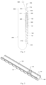
Fig. 1 is a structural schematic of an implant delivery system in accordance with an embodiment of the present invention; -
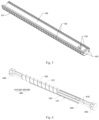
Fig. 2 is a structural schematic of a first inner slidable member in the implant delivery system in accordance with an embodiment of the present invention; -
Fig. 3 is a structural schematic of a second inner sliding member in the implant delivery system in accordance with an embodiment of the present invention; -
Fig. 4 is a schematic diagram showing the connection between the first inner sliding member, the second inner sliding member, and the circumferential positioning member in accordance with an embodiment of the present invention; -
Figs. 5a and 5b are schematic diagrams of the disassembly and assembly of the handle with the first inner sliding member and the second inner sliding member in accordance with an embodiment of the present invention, wherein one sub-handle is assembled inFig. 5a , and both of the two sub-handles of the handle are assembled inFig. 5b ; -
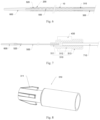
Fig. 6 is a schematic diagram showing the connection between the first distal end, the second distal end, the fourth distal end, the guide member, and the implant in the implant delivery system in accordance with an embodiment of the present invention; -
Fig. 7 is a schematic diagram showing the connection of the inner tube with the guide member and the first infusion tube in the implant delivery system in accordance with an embodiment of the present invention; -
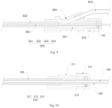
Fig. 8 is a structural schematic of an end portion of the jacking tube in the implant delivery system in accordance with an embodiment of the present invention; -
Fig. 9 is a schematic diagram showing the connection of the second proximal end of the jacking tube with the inner tube and the second infusion tube in the implant delivery system in accordance with an embodiment of the present invention; -
Fig. 10 is a schematic diagram showing showing the connection between the first proximal end of the outer tube and the jacking tube in the implant delivery system in accordance with an embodiment of the present invention; -
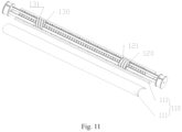
Fig. 11 is a schematic diagram showing the connection of the handle with the first inner sliding member and the second inner sliding member in accordance with another embodiment of the present invention. - In the drawings:
- 10 stent
- 110 handle
- 111 sub-handle
- 120 first inner sliding member;
- 121 first external thread, 122 raised limiting member, 123 first snap ring;
- 130 second inner sliding member;
- 131 second external thread, 132 sliding groove, 133 second snap ring;
- 200 outer tube;
- 210 outer tube connection assembly;
- 211 outer tube connector, 212 first sealing ring, 213 first sealing cap;
- 300 jacking tube;
- 310 head of the jacking tube;
- 311 hook;
- 320 jacking tube connection assembly;
- 321 jacking tube connector, 322 second sealing ring, 323 second sealing cap, 324 second branch connector;
- 400 circumferential positioning member;
- 410 arc-shaped plate, 420 positioning groove, 430 proximal connector, 440 distal connector;
- 500 inner tube;
- 510 inner tube connection assembly;
- 511 first connecting sleeve, 512 second connecting sleeve, 513 locking cap;
- 520 developing ring;
- 600 guide member;
- 710 first infusion tube, 720 Luer taper;
- 810 second infusion tube, 820 check valve.
- The objects, advantages and features of the invention will be more apparent upon reading the following detailed description of the proposed implant delivery system in connection with the accompanying figures. Note that the figures are much simplified and may not be drawn to scale, and their sole purpose is to facilitate easy and clear explanation of some embodiments of the invention.
- As used herein and in the appended claims, the singular forms of "a", "an", and "the", include plural references unless the context clearly dictates otherwise. As used in this specification and the appended claims, the term "or" is generally used to include the meaning of "and/or", unless the content clearly indicates otherwise; the terms "installed", "connected", "coupled" should be understood in a broad sense. For example, it can be a fixed connection, a detachable connection, or an integral connection, a mechanical connection, an electrical connection, a direct connection, or an indirect connection through an intermediate medium. It can be a communication between two elements or an interaction relationship between two elements. For those of ordinary skill in the art, the specific meaning of the above-mentioned terms in the present invention can be understood according to specific circumstances. Throughout the figures, same or analogous reference numerals indicate the same or analogous components or elements.
- In the present invention, the terms "proximal" and "distal" refer to the relative position, relative orientation, and direction of elements or actions relative to each other from the perspective of the operator using the implant delivery system, although the "distal" and "Proximal" is not restrictive, "proximal end" usually refers to the end of the implant delivery system close to the operator during normal operation, and "distal" usually refers to the end away from the operator, that is, the end that first enters the patient's body.
- The implant delivery system provided by the embodiment of the present invention is configured to deliver an implant into a diseased lumen such as a blood vessel. In this embodiment, the
stent 10 is used as an implant to be delivered for description, but it should not constitute a limitation to the present invention. - As shown in
Figs. 1 and6 , the implant delivery system includes ahandle 110, a first inner slidingmember 120, a second inner slidingmember 130, anouter tube 200, and a jackingtube 300. Thehandle 110 has a first cavity. The first inner slidingmember 120 and the second inner slidingmember 130 are located in the first cavity. Theouter tube 200 has a first proximal end and a first distal end opposite to each other. The first proximal end is connected to the first inner slidingmember 120. The jacking tube has a second proximal end and a second distal end opposite to each other. The second distal end is disposed in the outer tube, and the second proximal end is connected to the second inner slidingmember 130. - The
handle 110 is threadedly matched with the first inner slidingmember 120 and the second inner slidingmember 130 for screw transmission, and is configured to drive the first inner slidingmember 120 and the second inner slidingmember 130 to move linearly along the axis of thehandle 110 in two opposite directions, thereby driving theouter tube 200 and the jackingtube 300 to move in the two opposite directions. - The
stent 10 is delivered and released by the implant delivery system provided by the present invention. When thehandle 110 is rotated, the first inner slidingmember 120 can drive theouter tube 200 to withdraw by means of screw transmission, and thestent 10 is released with its volume expanded but length shortened, which results in a deviation from the predetermined position. At the same time, the second inner slidingmember 130 drives the jackingtube 300 to move to the predetermined position, thereby pushing thestent 10 to the predetermined position, so that thestent 10 is positioned accurately to ensure a treatment effect. - In the process of releasing the
stent 10, in order to ensure that the first inner slidingmember 120 and the second inner slidingmember 130 move linearly when thehandle 110 is lotating, the implant delivery system further includes acircumferential positioning member 400. Thecircumferential positioning member 400 is used to keep the first inner slidingmember 120 and the second inner slidingmember 130 fixed in the circumferential direction and moveable in the axial direction. - In addition, when the
stent 10 is released, the retracting distance of theouter tube 200 and the pushing distance of the jackingtube 300 need to meet a certain ratio, so that thestent 10 can accurately reach the predetermined position. The retracting distance of theouter tube 200 and the pushing distance of the jackingtube 300 can be calculated through simulation experiments. During operation, the retreating distance of theouter tube 200 is equal to the moving distance of the first inner slidingmember 120, and the pushing distance of the jackingtube 300 is equal to the moving distance of the second inner slidingmember 130. The moving distances of the first inner slidingmember 120 and the second inner slidingmember 130 rely on the rotation speed and the pitch. In the present invention, the first inner slidingmember 120 and the second inner slidingmember 130 are controlled to rotate by thesame handle 110, and both have the same rotation speed. The moving distances of the first inner slidingmember 120 and the second inner slidingmember 130 are respectively determined by the respective pitch. By setting the pitch ratio of the first inner slidingmember 120 and the second inner slidingmember 130, the first inner slidingmember 120 and the second inner slidingmember 130 can move according to an expected speed ratio, so that the retreating distance of theouter tube 200 and the pushing distance of the jackingtube 300 meets an expected ratio, so that thestent 10 can accurately reach the predetermined position. For those skilled in the art, it is common knowledge to set the pitch ratio of the two threaded segments according to the ratio of the known moving distances, so it will not be described in detail here. - Next, the first inner sliding
member 120, the second inner slidingmember 130, and thehandle 110 will be further described and illustrated in detail, but not limited to the structure described in the following embodiments. - Reference is made to
Figs. 1 to 4 , in an embodiment, the outer surface of the first inner slidingmember 120 is provided with a firstexternal thread 121, and the outer surface of the second inner sliding member is provided with a secondexternal thread 131. The thread directions of the firstexternal thread 121 and the secondexternal thread 131 are opposite. In a plane perpendicular to the axial direction of thehandle 110, the first inner slidingmember 120 may have an arc shape, preferably a semicircular arc shape, and the firstexternal thread 121 is provided on the convex surface of the first inner slidingmember 120. In a plane perpendicular to the axial direction of thehandle 110, the second inner slidingmember 130 may have an arc shape, preferably a semicircular arc shape. In this embodiment, the first inner slidingmember 120 and the second inner slidingmember 130 are both of semicircular arc shapes. The outer diameter of the second inner slidingmember 130 is equal in length to the outer diameter of the first inner slidingmember 120, and the inner diameters of the second inner slidingmember 130 and the first inner slidingmember 120 are also equal in length. In other embodiments of the present invention, the first inner sliding member and the second inner sliding member may have other shapes. In other embodiments of the present invention, the outer diameters of the first inner sliding member and the second inner sliding member can be the same or different. In this embodiment, the secondexternal thread 131 is provided on the convex surface of the second inner slidingmember 130. The concave surface of the first inner slidingmember 120 and the concave surface of the second inner slidingmember 130 are arranged opposite to each other (that is, when the first inner slidingmember 120 and the second inner slidingmember 130 are projected to a plane perpendicular to the axial direction of thehandle 110, the projections of the first inner slidingmember 120 and the second inner slidingmember 130 may form a circle). The first inner slidingmember 120 and the second inner slidingmember 130 are slidable relatively along the axial direction of thehandle 110. During the sliding process, the first inner slidingmember 120 and the second inner slidingmember 130 may overlap at least partially. This structural design can reduce the axial length of thehandle 110, reduce the size of the delivery system, and also make it easier to operate. - Further, the first inner sliding
member 120 has two first end surfaces extending along the axial direction of thehandle 110, and each of the first end surface may be provided with a raised limitingmember 122 extending along the axial direction of thehandle 110. The second inner slidingmember 130 has two second end surfaces extending along the axial direction of thehandle 110, and each of the second end surfaces may be correspondingly provided with a slidinggroove 132 extending along the axial direction of thehandle 110. The raised limitingmember 122 is installed in the slidinggroove 132 and is slidable along the slidinggroove 132 to realize the circumferential positioning of the first inner slidingmember 120 and the second inner slidingmember 130. The positions of the raised limitingmember 122 and the slidinggroove 132 can also be exchanged. That is, the raised limitingmember 122 is arranged on the second end surfaces of the second inner slidingmember 130, and the slidinggroove 132 is arranged on the first end surfaces of the first inner slidingmember 120. The raised limitingmember 122 can be a continuous member extending along the axial direction of thehandle 110, or can be a plurality of members spaced apart along the axial direction of thehandle 110. The first inner slidingmember 120 can be provided with a raised limiting member on one of the first end surfaces, or can be provided with raised limitingmembers 122 on both of the first end surfaces; accordingly, the second inner slidingmember 130 can be provided with a slidinggroove 132 on one of the second end surfaces, or can be provided with sliding grooves on both of the second end surfaces. In some embodiments, the raised limiting member and sliding grooves may not be provided, but the circumferential positioning between the first inner sliding member and the second inner sliding member is realized through specific structures. - Please continue to refer to
Figs. 1 and4 , thecircumferential positioning member 400 further includespositioning grooves 420 defined in the first inner slidingmember 120 and the second inner slidingmember 130, and thepositioning grooves 420 extends along the axial direction of thehandle 110. The first inner slidingmember 120 and the second inner slidingmember 130 are mounted to the arc-shapedplate 410 through thepositioning grooves 420 and are slidable along the arc-shapedplate 410. As shown inFig. 4 , preferably, two arc-shapedplates 410 are included, and the two arc-shapedplates 410 are arranged side by side and both extend along the axial direction of thehandle 110. Each of the two first end surfaces of the first inner slidingmember 120 is provided with apositioning groove 420, and each of the two second end surfaces of the second inner slidingmember 130 is defined with apositioning groove 420. The arc-shapedplate 410 may be an arc-shaped plate structure, and is symmetrically arranged by thepositioning grooves 420, so that the first inner slidingmember 120 and the second inner slidingmember 130 are balanced in force during movement. - The implant delivery system further includes a
proximal connector 430 and adistal connector 440 arranged at respective ends of the handle, and theproximal connector 430 and thedistal connector 440 are connected by the arc-shapedplate 410. The arc-shapedplate 410 has a third proximal end and a third distal end opposite to each other. The third proximal end of the arc-shapedplate 410 is connected to theproximal connector 430, and the third distal end of the arc-shapedplate 410 is connected to thedistal connector 440. After theproximal connector 430 and thedistal connector 440 are connected by the arc-shapedplate 410, the purpose of circumferential position limiting can be achieved. Theproximal connector 430 is connected to the fourth proximal end of theinner tube 500. When the handle is rotated, theproximal connector 430 is likely to be rotated with the handle in the circumferential direction, thereby driving theinner tube 500 to rotate in the circumferential direction, which affects the accuracy in positioning the stent. In this embodiment, after theproximal connector 430 and thedistal connector 440 are connected by the arc-shapedplate 410, the circumferential position limiting can be achieved, thereby solving the problem that theproximal connector 430 will rotate with the handle along the circumferential direction. In some embodiments, the number of the arc-shapedplates 410 may be two, and the concave surfaces of the two arc-shapedplates 410 face with each other and define a second cavity. In some embodiments, theproximal connector 430 defines a first blind hole therein, and the third proximal end of the arc-shapedplate 410 is installed in the first blind hole; thedistal connector 440 defines therein a second blind hole (not shown in the figure), and the third distal end of the arc-shapedplate 410 is installed in the second blind hole. The shapes of the first blind hole and the second blind hole are adapted to the shape of the ends of the arc-shapedplate 410. In other words, when the arc-shapedplate 410 has an arc plate structure, the first blind hole and the second blind hole are arc-shaped holes. In this embodiment, the number of the first blind hole and the second blind hole are both two for installing the two arc-shapedplates 410. In some embodiments, thedistal connector 440 further defines therein a first through hole, and the jackingtube 300 and theouter tube 200 pass through the first through hole. - Further, the
handle 110 may include a first cavity having a hollow tube-like shape, and the first inner slidingmember 120 and the second inner slidingmember 130 are arranged in thehandle 110. Thehandle 110 is preferably composed of two parts. Please refer toFigs. 5a and 5b , thehandle 110 includes two sub-handles 111. In a plane perpendicular to the axial direction of thehandle 110, the inner cavity of each of the sub-handles 111 has a semicircular arc shape, and the radial dimensions of the twosub-handles 111 are completely the same. A first internal thread and a second internal thread are provided on the concave surface of each of the sub-handles 111. The twosub-handles 111 are connected to form a cavity penetrating along the axial direction of thehandle 110 to accommodate the first inner slidingmember 120 and the second inner slidingmember 130. The first internal thread is matched with the firstexternal thread 121 for screw transmission, and the second internal thread is matches with the secondexternal thread 131 for screw transmission. - In addition, referring to
Figs. 1 and6 , the implant delivery system provided by the embodiments of the present invention further includes aninner tube 500, aguide member 600, afirst infusion tube 710 and asecond infusion tube 810. - As shown in
Fig. 6 , theinner tube 500 is arranged in the jackingtube 300. In other words, theinner tube 500, the jackingtube 300, and theouter tube 200 are sleeved in the order from the inside to the outside. Theinner tube 500 has a fourth proximal end and a fourth distal end opposite to each other. The fourth distal end of theinner tube 500 protrudes from the second distal end of the jackingtube 300 and extends inside theouter tube 200. An annular cavity is formed between theinner tube 500 and theouter tube 200, and thestent 10 can be compressed into the annular cavity. The fourth distal end of theinner tube 500 is connected to theguide member 600. Theguide member 600 usually has a tapered structure, and the tip of the tapered structure is away from the fourth end of the inner tube. When thestent 10 is not released, the guidingmember 600 abuts against the first distal end of theouter tube 200 with a smooth transition therebetween. - As shown in
Fig. 7 , the fourth proximal end of theinner tube 500 protrudes from the second proximal end of the jackingtube 300 and extends in the second inner slidingmember 130. The fourth proximal end of theinner tube 500 is connected to thefirst infusion tube 710, and the end of thefirst infusion tube 710 away from theinner tube 500 can be provided with aluer taper 720 so as to be connected with an external syringe to discharge the air in theinner tube 500 during the use. - Furthermore, the fourth proximal end of the
inner tube 500 can also be connected to theproximal connector 430. In some embodiments, theproximal connector 430 defines therein a second through hole penetrating in the axial direction, and theinner tube 500 extends through the first through hole, the second cavity, and the second through hole. The present invention does not particularly limit the connection mode of theinner tube 500 with theproximal connector 430, and the detachable mode is preferred, which improves the convenience in operation. In this way, when thestent 10 is completely released, theinner tube 500 and theproximal connector 430 can be disconnected. - In detail, the fourth proximal end of the
inner tube 500 is provided with an innertube connection assembly 510. The innertube connection assembly 510 may include a first connectingsleeve 511, a second connectingsleeve 512, and alocking cap 513. The first connectingsleeve 511 is used to connect the fourth proximal end of theinner tube 500 and thefirst infusion tube 710, the second connectingsleeve 512 is sleeved over the first connectingsleeve 511, and thelocking cap 513 is used to detachably connect the first connectingsleeve 511 and the second connectingsleeve 512. For example, the lockingcap 513 is threadedly connected to the second connectingsleeve 512. When thelocking cap 513 is tightened, the first connectingsleeve 511 and the second connectingsleeve 512 are tightly connected. When thelocking cap 513 is loosen, the first connectingsleeve 511 and the first connectingsleeve 511 are relatively movable. The second connectingsleeve 512 is connected to theproximal connector 430. In this way, the position of the fourth proximal end of theinner tube 500 can be fixed by tightening thelocking cap 513, which prevents theinner tube 500 from moving in the axial direction due to friction during the release of thestent 10 and causing displacement. When thestent 10 is released, theguide member 600 is separated from theouter tube 200, which causes an inconvenience in withdrawning the implant delivery system from the human body. However, after thestent 10 is released, the first connectingsleeve 511 and the second connectingsleeve 512 are disconnected, and thefirst infusion tube 710 can be pulled to make theinner tube 500 to move proximally so that theguide member 600 abuts aginst theouter tube 200 again, which facilitates withdrawal of the implant delivery system. It should be understood that the fourth proximal end of theinner tube 500 can also be connected to other elements such as an external mechanism to achieve the same purpose. - The fourth distal end of the
inner tube 500 is further provided with a developingring 520 to facilitate positioning of thestent 10. The number of the developingring 520 may be one or more. - Please continue to refer to
Figs. 6, 8 and9 , the second distal end of the jackingtube 300 is provided with ahead 310, and thehead 310 has a holdingstructure 311. The holdingstructure 311 is used for holding and releasing thestent 10. Specifically, thehead 310 of the jacking tube is sleeved over the jackingtube 300, and the part of the jackingtube 300 away from the second distal end of the jackingtube 300 is preferably designed as an umbrella-shaped structure, and the outer surface of the umbrella-shaped structure is provided with the holdingstructure 311. Preferably, the holdingstructure 311 is a hook, the number of the hook is at least two, and the at least two of the hooks can be arranged at intervals along the circumferential direction of thehead 310 of the jacking tube. - As shown in
Fig. 9 , the second proximal end of the jackingtube 300 is provided with a jackingtube connection assembly 320 used to connect the jackingtube 300 with theinner tube 500, and the jackingtube connection assembly 320 is also used to connect with the second inner slidingmember 130. - The jacking
tube connection assembly 320 includes a jackingtube connector 321 arranged at the second proximal end of the jackingtube 300, and a second connecting hole is defined in the jackingtube connector 321, and the jacking tube connector is sleeved over the theinner tube 500 through the second connecting hole and is slidable along theinner tube 500. The jackingtube connector 321 is in sealing connection with theinner tube 500. To this end, the jackingtube connection assembly 320 further includes asecond sealing ring 322 and asecond sealing cap 323, and thesecond sealing ring 322 is sleeved over theinner tube 500 and fastened by thesecond sealing cap 323 so that it is in close contact with the jackingtube connector 321 to achieve the purpose of sealing. - The jacking
tube connector 321 may further be defined with a second snap groove. Correspondingly, asecond snap ring 133 can be provided on the inner wall of the second inner slidingmember 130. The jackingtube 300 can be detachably connected to the second inner slidingmember 130 by means of the fit between the second snap groove and thesecond snap ring 133. - Referring to
Fig. 10 , the first proximal end of theouter tube 200 is provided with an outertube connection assembly 210. Theouter tube 200 is connected to the jackingtube 300 at the outside of the jackingtube 300 by the outertube connection assembly 210 and is slidable along the jackingtube 300, and the outer tube connection assembly shall be in sealing connection with the jackingtube 300. Specifically, the outertube connection assembly 210 includes anouter tube connector 211, afirst sealing ring 212, and asecond sealing cap 213. A first connecting hole is defined in thetube connector 211. The first connecting hole has an end fixedly connected to theouter tube 200, and a further end sleeved over the jackingtube 300. Thefirst sealing ring 212 is sleeved over the jackingtube 300 and is in tight contact with theouter tube 200 by means of thefirst sealing cap 213 for sealing. - The
outer tube connector 211 may further be defined with a first snap groove, and the first inner slidingmember 120 may be correspondingly provided with afirst snap ring 123. Theouter tube 200 can be detachably connected to the first inner slidingmember 120 by means of the fit between the first snap groove and thefirst snap ring 123. - In addition, the
second infusion tube 810 is used to discharge the air between theouter tube 200 and the jackingtube 300 and the air between the jackingtube 300 and theinner tube 500. In detail, the arrangement of the second infusion tube may be selected from, but not limited to, the following two options:
The first arrangement (not shown): the outer tube connector is provided with a first branch connector in wich a third connecting hole is defined. The second infusion tube is inserted in the third connecting hole. The end of the second infusion tube away from the first branch connector is provided with a check valve. - The second arrangement: as shown in
Fig. 9 , the jackingtube connection assembly 320 further includes asecond branch connector 324 in which a fourth connecting hole is defined. Thesecond infusion tube 810 is inserted into the fourth connecting hole so that the jackingtube 300 is in communication with thesecond infusion tube 810. The end of thesecond infusion tube 810 away from the jackingtube connector 321 is provided with acheck valve 820. It should be noted that various existing methods can be used to realize the fixed connection between the components when assembling the components. For example, theguide member 600 may be injection molded on the fourth distal end of theinner tube 500, and thehead 310 of the jacking tube may be injection molded on or in hot melt connection with the second distal end of the jackingtube 300, and theouter tube connector 211 may be injection molded on the first proximal end of theouter tube 200, theinner tube 500 and the first connectingsleeve 511 may be bonded by glue, thesecond infusion tube 810 and thesecond branch connector 324 may be bonded by glue. - The method of using the implant delivery system of the present invention will be described in the following by taking the delivery of the
stent 10 into the diseased blood vessel as an example. - Before the surgical operation begins, the
stent 10 is first compressed into theouter tube 200; then a syringe is connected to thecheck valve 820, and a liquid such as heparin saline is injected into the implant delivery system by the syringe to discharge the air between theinner tube 500 and the jackingtube 300 as well as the air between the jackingtube 300 and theouter tube 200; and a syringe is connected to theLuer taper 720 to inject liquid into theinner tube 500 to discharge the air in theinner tube 500; the outer wall of theouter tube 200 is then cleaned by heparin saline. - After the surgical operation begins, the blood vessel is first punctured, and then under the supervision of the X-ray machine, the
guide member 600 is sent to the area where the lesion locates by using a common means (such as a guide wire) to make the developingring 520 coincide in position with the location where and thestent 10 is to be placed. Then thehandle 110 is rotated to move theouter tube 200 proximally, and thestent 10 is released and expanded. At the same time, the jackingtube 300 pushes thestent 10 to move distally so that thestent 10 is finally located at a predetermined position, and theguide member 600 is separated from theouter tube 200; thehandle 110 is continuously rotated until thestent 10 is completely released. Subsequently, the lockingcap 513 is released, and thefirst infusion tube 710 is pulled proximally to drive theinner tube 500 to move proximally until theguide member 600 contacts theouter tube 200 again, and finally the implant delivery system is withdrawn from the body. - In the process of releasing the
stent 10, if the operator is not satisfied with the position of thestent 10, before thestent 10 is completely released, thehandle 110 can be reversely rotated to move theouter tube 200 toward the distal end, while the jackingtube 300 is retracted to pull thestent 10 back into theouter tube 200; then, the operator readjusts the position of thestent 10 and releases it. - In the above embodiments, the first inner sliding
member 120 and the second inner slidingmember 130 are arc-shaped when viewed along the axial direction of thehandle 110, which is taken as an example to describe the structure of the implant delivery system. However, structures of the first inner slidingmember 120 and the second inner slidingmember 130 are not limited thereto. For example, in another embodiment, as shown inFig. 11 , thehandle 110 has a first cavity extending axially with a cylinder shape, and the wall of the first cavity is formed with a first internal thread and a second internal thread, and the first internal thread and the second internal thread are arranged along the axial direction of thehandle 110. The first inner slidingmember 120 has a hollow tube-shaped structure with a firstexternal thread 121 provided on its outer surface, and the first inner slidingmember 120 is disposed in the first cavity of thehandle 110, and the firstexternal thread 121 is matched with the first internal thread. The second inner slidingmember 130 has a hollow tube-shaped structure with a secondexternal thread 131 disposed on its outer surface, and the second inner slidingmember 130 is disposed in the first cavity of thehandle 110 and is arranged coaxially with the first inner slidingmember 120, and the secondexternal thread 131 is threadedly matched with the second internal thread. - In short, the present invention does not strictly limit the specific structures of the first inner sliding member, the second inner sliding member, and the handle, as long as the first inner sliding member and the second inner sliding member can simultaneously move linearly in opposite directions in response to the rotation of the handle after they are threadedly connected to the handle.
- The advantage of the implant delivery system provided in the embodiments of the present invention is as follows. On one hand, the
outer tube 200 and the jackingtube 300 are simultaneously driven by the driving assembly 100 to move linearly in opposite directions, so that thestent 10 gradually moves from the distal end to the proximal end, and thestent 10 is pushed by the jackingtube 300 to move distally to supplement the displacement caused by the contraction of thestent 10 due to expansion, so that thestent 10 can be delivered to a predetermined position to ensure the treatment effect. On the other hand, theouter tube 200 and the jackingtube 300 are driven to move by means of screw feeding, which facilitates the control of the moving distance of theouter tube 200 and the jackingtube 300, so as to achieve accurat positioning of thestent 10 and reduced requirement for the operator's experience. - The implant delivery system provided in the embodiments of the present invention has further advantage as follows. The
proximal connector 430 and thedistal connector 440 are connected by the arc-shapedplate 410, which can achieve the purpose of circumferential position limiting, thereby avoiding the situation thatinner tube 500 is driven by theproximal connector 430 to rotate along the circumferential direction with the handle, which affects the accuracy in positioning the stent. - Although the present invention is disclosed as above, it is not limited thereto. It is apparent that those skilled in the art can make various modifications and variations to the present invention without departing from the scope thereof. Accordingly, the invention is intended to embrace all such modifications and variations if they fall within the scope of the appended claims.
Claims (15)
- An implant (10) delivery system, comprising: a handle (110), a first inner sliding member (120), a second inner sliding member (130), an inner tube (500), an outer tube (200), and a jacking tube (300), wherein the handle (110) has a first cavity in which the first inner sliding member (120) and the second inner sliding member (130) are located;the outer tube (200) has a first proximal end and a first distal end opposite to each other, and the first proximal end is connected to the first inner sliding member (120); the jacking tube (300) has a second proximal end and a second distal end opposite to each other, the second distal end is arranged in the outer tube (200), and the second proximal end is connected to the second inner sliding member (130); the inner tube (500) extends through the outer tube (200) and the jacking tube (300), and a cavity configured to receive a implant (10) is formed between the inner tube (500) and the outer tube (200); and the second distal end is configured for connecting with a proximal part of the implant (10);the handle (110) is threadedly matched with the first inner sliding member and the second inner sliding member (130) for screw transmission, and configured to drive the first inner sliding member (120) and the second inner sliding member (130) to move linearly along an axis of the handle (110) in opposite directions so as to drive the outer tube (200) and the jacking tube (300) to move in the opposite directions to release the implant (10) from a distal end to a proximal end thereof;wherein the implant (10) delivery system further comprises a proximal connector (430) and a distal connector (440) provided at respective ends of the handle (110), the proximal connector (430) and the distal connector (440) are connected by two arc-shaped plates (410) having concave surfaces which are arranged opposite to each other and define a second cavity; the distal connector (440) is defined with a first through hole penetrating in an axial direction; the proximal connector (430) is connected to a proximal end of the inner tube (500);wherein a positioning groove (420) extending along an axial direction of the handle (110) is defined in each of the first inner sliding member (120) and the second inner sliding member (130), and the first inner sliding member (120) and the second inner sliding member (130) are slidably connected to an arc-shaped plate (410) through the positioning groove (420); the jacking tube (300) passes through the first through hole.
- The implant (10) delivery system according to claim 1, wherein an outer surface of the first inner sliding member (120) is provided with a first external thread (121), and an outer surface of the second inner sliding member (130) is provided with a second external thread (131), thread directions of the first external thread (121) and the second external thread (131) are opposite;
wherein an inner surface of the handle (110) is provided with a first internal thread and a second internal thread, and the first internal thread of the handle (110) is threadedly matched with the first external thread (121) of the first inner sliding member (120) for screw transmission, and the second internal thread of the handle (110) is threadedly matched with the second external thread (131) of the second inner sliding member (130) for screw transmission. - The implant (10) delivery system according to claim 1, wherein the handle (110) comprises two sub-handles (111) having inner cavities, and each of the inner cavities has a semicircular arc shape on a cross section perpendicular to an axial direction of the handle (110).
- The implant (10) delivery system according to any one of claims 1 to 3, wherein each of the first inner sliding member (120) and the second inner sliding member (130) has an arc shape, preferably a semicircular arc shape, on a cross section perpendicular to the axis of the handle (110), and a concave surface of the first inner sliding member (120) is arranged opposite to a concave surface of the second inner sliding member (130).
- The implant (10) delivery system of claim 1, wherein the first inner sliding member (120) has two first end surfaces extending along the axial direction of the handle (110), the positioning groove (420) is defined in each of the two first end surfaces, and the first inner sliding member (120) is slidably connected to the two arc-shaped plates (410) through the two positioning grooves (420); the second inner sliding member (130) has two second end surfaces extending along the axial direction of the handle (110), the positioning groove (420) is further defined in each of the two second end surfaces, and the second inner sliding member (130) is slidably connected to the two arc-shaped plates (410) through the two positioning grooves (420);
wherein the first end surface is provided with a raised limiting member (122), the second end surface is defined with a sliding groove (132) extending along the axial direction of the handle (110), and the limiting member is installed in the sliding groove (132); or, the first end surface is defined with a sliding groove, the second end surface is provided with a raised limiting member (122) extending along the axial direction of the handle (110), and the limiting member is installed in the sliding groove (132). - The implant (10) delivery system according to claim 1, wherein the proximal connector (430) is defined with a second through hole penetrating in the axial direction, and the inner tube (500) extends through the first through hole, the second cavity and the second through hole.
- The implant (10) delivery system according to claim 1, wherein the arc-shaped plate (410) has a third proximal end and a third distal end opposite to each other; a first blind hole is defined in the proximal connector (430), and the third proximal end of the arc-shaped plate (410) is installed in the first blind hole; a second blind hole is defined in the distal connector (440), and the third distal end of the arc-shaped plate (410) is installed in the second blind hole.
- The implant (10) delivery system according to claim 1, wherein further comprising a head of the jacking tube (310) arranged at the second distal end of the jacking tube (300), and the head is provided with a holding structure for holding and releasing the implant (10);
wherein the holding structure comprises a plurality of hooks (311) spaced apart along a circumferential direction of the head of the jacking tube (310). - The implant (10) delivery system according to claim 1, wherein further comprising a guide member (600), and the inner tube (500) has a fourth proximal end and a fourth distal end opposite to each other, the fourth distal end of the inner tube (500) protrudes from the first distal end of the outer tube (200) and is connected to the guide member (600);
wherein further comprising at least a developing ring (520) arranged at the fourth distal end of the inner tube (500). - The implant (10) delivery system according to claim 1, wherein further comprising a guide member (600), and the inner tube (500) has a fourth proximal end and a fourth distal end opposite to each other, the fourth distal end of the inner tube (500) protrudes from the first distal end of the outer tube (200) and is connected to the guide member (600);wherein the first proximal end of the outer tube (200) is connected to an outer wall of the jacking tube (300) through an outer tube connection assembly (210), and the outer tube (200) is slidable along the outer wall of the jacking tube (300);wherein the outer tube connection assembly (210) comprises an outer tube connector (211), a first sealing ring (212) and a first sealing cap (213); the outer tube connector (211) has a first connection hole whose one end is fixedly connected to the outer tube (200), a further end is sleeved over the jacking tube (300); and the first sealing ring (212) is sleeved over the jacking tube (300) and is in sealing connection with the outer tube (200) when the first sealing cap (213) is tightened.
- The implant (10) delivery system according to claim 10, wherein the outer tube connector (211) is further defined with a first snap groove, the first inner sliding member (120) is provided with a first snap ring (123), and the first snap groove is detachably connected to the first snap ring (123).
- The implant (10) delivery system according to claim 10, wherein the second proximal end of the jacking tube (300) is provided with a jacking tube connection assembly (320) comprising a jacking tube connector (321), wherein the jacking tube connector (321) is arranged at the second proximal end of the jacking tube (300), and the jacking tube connector (321) is defined with a second connecting hole through which the jacking tube connector (321) is sleeved over the inner tube (500) and is slidable along the inner tube (500);
wherein the jacking tube connection assembly further comprises a second sealing ring (322) and a second sealing cap (323), the second sealing ring (322) is sleeved over the inner tube (500), the second sealing cap (323) is used to fasten the second sealing ring (322) so that the jacking tube connector (321) is in sealing connection with the inner tube (500). - The implant (10) delivery system according to claim 10, wherein the second proximal end of the jacking tube (300) is provided with a jacking tube connection assembly (320) comprising a jacking tube connector (321), wherein the jacking tube connector (321) is arranged at the second proximal end of the jacking tube (300), and the jacking tube connector (321) is defined with a second connecting hole through which the jacking tube connector (321) is sleeved over the inner tube (500) and is slidable along the inner tube (500);
wherein the jacking tube connector (321) is defined with a second snap groove, the second inner sliding member (130) is provided with a second snap ring (133), and the second snap groove is detachably connected to the second snap ring (133). - The implant (10) delivery system according to claim 12, wherein comprising a first infusion tube (710) and a second infusion tube (810); the fourth proximal end of the inner tube (500) protrudes from the second proximal end of the jacking tube (300) and is in communication with the first infusion tube (710); the outer tube connector (211) is provided with a first branch connector, and a third connecting hole is defined in the first branch connector and is in communication with the second infusion tube (810); or,the tube jacking tube connector (321) is provided with a second branch connector (324), and a fourth connecting hole is defined in the second branch connector (324) and is in communication with the second infusion tube (810);wherein the fourth proximal end of the inner tube (500) is provided with an inner tube connection assembly (510) comprising a first connecting sleeve (511), a second connecting sleeve (512) and a locking cap (513); the first connecting sleeve (511) is used to connect the inner tube (500) and the first infusion tube (710), the second connecting sleeve (512) is sleeved over the first connecting sleeve (511) and is used to fix the fourth proximal end of the inner tube (500), and the locking cap (513) is used to lock the second connecting sleeve (512), the first connecting sleeve (511) and the first infusion tube (710) in position.
- The implant (10) delivery system according to any one of claims 1 to 3, wherein the first inner sliding member (120) and the second inner sliding member (130) are shaped as two hollow tube-shaped structures arranged coaxially with each other.
Applications Claiming Priority (2)
| Application Number | Priority Date | Filing Date | Title |
|---|---|---|---|
| CN201911349231.2A CN110882096B (en) | 2019-12-24 | 2019-12-24 | Implant delivery system |
| PCT/CN2020/113615 WO2021128940A1 (en) | 2019-12-24 | 2020-09-04 | Implant delivery system |
Publications (3)
| Publication Number | Publication Date |
|---|---|
| EP4082491A1 EP4082491A1 (en) | 2022-11-02 |
| EP4082491A4 EP4082491A4 (en) | 2023-01-25 |
| EP4082491B1 true EP4082491B1 (en) | 2025-07-02 |
Family
ID=69752975
Family Applications (1)
| Application Number | Title | Priority Date | Filing Date |
|---|---|---|---|
| EP20905091.3A Active EP4082491B1 (en) | 2019-12-24 | 2020-09-04 | Implant delivery system |
Country Status (8)
| Country | Link |
|---|---|
| EP (1) | EP4082491B1 (en) |
| JP (1) | JP7447273B2 (en) |
| KR (1) | KR102665074B1 (en) |
| CN (1) | CN110882096B (en) |
| AR (1) | AR120907A1 (en) |
| BR (1) | BR112022012539A2 (en) |
| ES (1) | ES3039937T3 (en) |
| WO (1) | WO2021128940A1 (en) |
Families Citing this family (7)
| Publication number | Priority date | Publication date | Assignee | Title |
|---|---|---|---|---|
| CN110882096B (en) * | 2019-12-24 | 2024-11-15 | 上海蓝脉医疗科技有限公司 | Implant delivery system |
| WO2022173790A1 (en) * | 2021-02-10 | 2022-08-18 | Silara Medtech Inc. | Driving handle, apparatus and method for recapturing an implant |
| CN113558834B (en) * | 2021-08-09 | 2024-04-26 | 广东脉搏医疗科技有限公司 | Connection assembly for cardiovascular implant |
| CN116035765A (en) * | 2021-10-28 | 2023-05-02 | 上海臻亿医疗科技有限公司 | Implant delivery device and implant delivery system |
| CN116250970B (en) * | 2023-03-31 | 2025-09-23 | 上海微创心通医疗科技有限公司 | Interventional Handpiece and Interventional System |
| CN119700372B (en) * | 2023-09-27 | 2026-01-06 | 深圳市健心医疗科技有限公司 | A support device for a conveyor |
| CN118892383B (en) * | 2024-10-09 | 2025-01-24 | 北京华脉泰科医疗器械股份有限公司 | Deep vein thrombosis removal device |
Family Cites Families (17)
| Publication number | Priority date | Publication date | Assignee | Title |
|---|---|---|---|---|
| GB0203177D0 (en) * | 2002-02-11 | 2002-03-27 | Anson Medical Ltd | An improved control mechanism for medical catheters |
| KR100536405B1 (en) * | 2002-09-09 | 2005-12-14 | 사회복지법인 삼성생명공익재단 | Apparatus for coronary angioplasty capable of finely adjusting a catheter |
| US7691095B2 (en) * | 2004-12-28 | 2010-04-06 | St. Jude Medical, Atrial Fibrillation Division, Inc. | Bi-directional steerable catheter control handle |
| US8623064B2 (en) * | 2010-04-30 | 2014-01-07 | Medtronic Vascular, Inc. | Stent graft delivery system and method of use |
| CN102283728B (en) * | 2011-06-28 | 2014-09-10 | 先健科技(深圳)有限公司 | Lumen bracket conveying system |
| US9393140B2 (en) * | 2012-04-27 | 2016-07-19 | Medtronic Vascular, Inc. | Reconfigurable stent-graft delivery system and method of use |
| US10285833B2 (en) * | 2012-08-10 | 2019-05-14 | Lombard Medical Limited | Stent delivery systems and associated methods |
| CN106308986B (en) * | 2015-07-01 | 2018-06-01 | 微创心脉医疗科技(上海)有限公司 | A kind of modular catheter for implantation material transport system |
| CN106691648A (en) * | 2016-12-20 | 2017-05-24 | 心凯诺医疗科技(上海)有限公司 | Accurately-releasable self-expanding stent conveying system |
| CN109248012B (en) * | 2017-07-14 | 2020-12-25 | 先健科技(深圳)有限公司 | Implant delivery system |
| CN209075051U (en) * | 2018-01-31 | 2019-07-09 | 常州乐奥医疗科技股份有限公司 | From swollen stent delivery system and its conveying handle |
| CN209075052U (en) * | 2018-01-31 | 2019-07-09 | 常州乐奥医疗科技股份有限公司 | From swollen stent delivery system and its conveying handle |
| CN108403269A (en) * | 2018-03-07 | 2018-08-17 | 普霖医疗科技(广州)有限公司 | Integrated bracket conveyer |
| US11517458B2 (en) * | 2018-04-05 | 2022-12-06 | Microvention, Inc. | Implant delivery system |
| CN211674738U (en) * | 2019-12-24 | 2020-10-16 | 上海蓝脉医疗科技有限公司 | an implant delivery system |
| CN110882096B (en) * | 2019-12-24 | 2024-11-15 | 上海蓝脉医疗科技有限公司 | Implant delivery system |
| CN120907505B (en) * | 2025-10-09 | 2026-01-06 | 江西省交投养护科技集团有限公司 | A method and system for analyzing the settlement of roadbeds during reconstruction and expansion |
-
2019
- 2019-12-24 CN CN201911349231.2A patent/CN110882096B/en active Active
-
2020
- 2020-09-04 EP EP20905091.3A patent/EP4082491B1/en active Active
- 2020-09-04 BR BR112022012539A patent/BR112022012539A2/en unknown
- 2020-09-04 WO PCT/CN2020/113615 patent/WO2021128940A1/en not_active Ceased
- 2020-09-04 KR KR1020227025323A patent/KR102665074B1/en active Active
- 2020-09-04 JP JP2022539003A patent/JP7447273B2/en active Active
- 2020-09-04 ES ES20905091T patent/ES3039937T3/en active Active
- 2020-12-23 AR ARP200103654A patent/AR120907A1/en active IP Right Grant
Also Published As
| Publication number | Publication date |
|---|---|
| JP7447273B2 (en) | 2024-03-11 |
| JP2023508958A (en) | 2023-03-06 |
| EP4082491A1 (en) | 2022-11-02 |
| EP4082491A4 (en) | 2023-01-25 |
| ES3039937T3 (en) | 2025-10-27 |
| CN110882096B (en) | 2024-11-15 |
| KR102665074B1 (en) | 2024-05-20 |
| KR20220119679A (en) | 2022-08-30 |
| BR112022012539A2 (en) | 2022-09-06 |
| AR120907A1 (en) | 2022-03-30 |
| CN110882096A (en) | 2020-03-17 |
| WO2021128940A1 (en) | 2021-07-01 |
Similar Documents
| Publication | Publication Date | Title |
|---|---|---|
| EP4082491A1 (en) | Implant delivery system | |
| US11950807B2 (en) | Puncturing device and anchoring device | |
| EP3398568B1 (en) | Delivery system and lumen stent system | |
| CN106963516B (en) | Intracavitary orthotopic fenestration sting device | |
| EP4458388A1 (en) | Interventional injection device and interventional injection system | |
| CN109953843B (en) | Delivery and release device for aortic stent | |
| CN110974502B (en) | Conveyor and implant conveying system | |
| CN211674738U (en) | an implant delivery system | |
| CN110025415B (en) | Handle of medical implant release system | |
| CN101224145A (en) | A locking device for a medical device delivery system in a human body | |
| EP3762085A1 (en) | Catheter assembly and systems and methods of using same | |
| CN107518968A (en) | Self-expanding stent induction system and its gear drive component | |
| EP3219262A1 (en) | Robotic embolisation device and system | |
| CN207837684U (en) | Intracavitary orthotopic fenestration sting device | |
| CN112315638A (en) | Support conveying system | |
| CN108245291A (en) | Self-expanding stent transport system and its conduit tube component | |
| CN116115402B (en) | A proximal end structure of a conveyor and a conveying system | |
| CN206852687U (en) | Self-expanding stent induction system and its gear drive component | |
| CN109350322B (en) | Double-bracket implantation device | |
| CN206852686U (en) | Self-expanding stent induction system and its conduit tube component | |
| CN119523705B (en) | A conveyor handle and its conveying system | |
| CN114533358B (en) | Conveyor device | |
| CN121549920A (en) | Conveying device and endoscopic surgical equipment | |
| CN119302792A (en) | A glaucoma catheter implantation system | |
| CN121445448A (en) | Combined thrombolysis device for intracranial vein and operation method thereof |
Legal Events
| Date | Code | Title | Description |
|---|---|---|---|
| STAA | Information on the status of an ep patent application or granted ep patent |
Free format text: STATUS: THE INTERNATIONAL PUBLICATION HAS BEEN MADE |
|
| PUAI | Public reference made under article 153(3) epc to a published international application that has entered the european phase |
Free format text: ORIGINAL CODE: 0009012 |
|
| STAA | Information on the status of an ep patent application or granted ep patent |
Free format text: STATUS: REQUEST FOR EXAMINATION WAS MADE |
|
| 17P | Request for examination filed |
Effective date: 20220708 |
|
| AK | Designated contracting states |
Kind code of ref document: A1 Designated state(s): AL AT BE BG CH CY CZ DE DK EE ES FI FR GB GR HR HU IE IS IT LI LT LU LV MC MK MT NL NO PL PT RO RS SE SI SK SM TR |
|
| A4 | Supplementary search report drawn up and despatched |
Effective date: 20221223 |
|
| RIC1 | Information provided on ipc code assigned before grant |
Ipc: A61F 2/95 20130101ALI20221219BHEP Ipc: A61F 2/966 20130101AFI20221219BHEP |
|
| DAV | Request for validation of the european patent (deleted) | ||
| DAX | Request for extension of the european patent (deleted) | ||
| GRAP | Despatch of communication of intention to grant a patent |
Free format text: ORIGINAL CODE: EPIDOSNIGR1 |
|
| STAA | Information on the status of an ep patent application or granted ep patent |
Free format text: STATUS: GRANT OF PATENT IS INTENDED |
|
| INTG | Intention to grant announced |
Effective date: 20250410 |
|
| GRAS | Grant fee paid |
Free format text: ORIGINAL CODE: EPIDOSNIGR3 |
|
| GRAA | (expected) grant |
Free format text: ORIGINAL CODE: 0009210 |
|
| STAA | Information on the status of an ep patent application or granted ep patent |
Free format text: STATUS: THE PATENT HAS BEEN GRANTED |
|
| AK | Designated contracting states |
Kind code of ref document: B1 Designated state(s): AL AT BE BG CH CY CZ DE DK EE ES FI FR GB GR HR HU IE IS IT LI LT LU LV MC MK MT NL NO PL PT RO RS SE SI SK SM TR |
|
| REG | Reference to a national code |
Ref country code: GB Ref legal event code: FG4D |
|
| REG | Reference to a national code |
Ref country code: CH Ref legal event code: EP |
|
| REG | Reference to a national code |
Ref country code: DE Ref legal event code: R096 Ref document number: 602020054009 Country of ref document: DE |
|
| REG | Reference to a national code |
Ref country code: IE Ref legal event code: FG4D |
|
| PGFP | Annual fee paid to national office [announced via postgrant information from national office to epo] |
Ref country code: DE Payment date: 20250919 Year of fee payment: 6 |
|
| PGFP | Annual fee paid to national office [announced via postgrant information from national office to epo] |
Ref country code: GB Payment date: 20250919 Year of fee payment: 6 |
|
| REG | Reference to a national code |
Ref country code: ES Ref legal event code: FG2A Ref document number: 3039937 Country of ref document: ES Kind code of ref document: T3 Effective date: 20251027 |
|
| REG | Reference to a national code |
Ref country code: NL Ref legal event code: MP Effective date: 20250702 |
|
| PG25 | Lapsed in a contracting state [announced via postgrant information from national office to epo] |
Ref country code: PT Free format text: LAPSE BECAUSE OF FAILURE TO SUBMIT A TRANSLATION OF THE DESCRIPTION OR TO PAY THE FEE WITHIN THE PRESCRIBED TIME-LIMIT Effective date: 20251103 |
|
| PG25 | Lapsed in a contracting state [announced via postgrant information from national office to epo] |
Ref country code: NL Free format text: LAPSE BECAUSE OF FAILURE TO SUBMIT A TRANSLATION OF THE DESCRIPTION OR TO PAY THE FEE WITHIN THE PRESCRIBED TIME-LIMIT Effective date: 20250702 |
|
| REG | Reference to a national code |
Ref country code: AT Ref legal event code: MK05 Ref document number: 1808417 Country of ref document: AT Kind code of ref document: T Effective date: 20250702 |
|
| PG25 | Lapsed in a contracting state [announced via postgrant information from national office to epo] |
Ref country code: IS Free format text: LAPSE BECAUSE OF FAILURE TO SUBMIT A TRANSLATION OF THE DESCRIPTION OR TO PAY THE FEE WITHIN THE PRESCRIBED TIME-LIMIT Effective date: 20251102 |
|
| PG25 | Lapsed in a contracting state [announced via postgrant information from national office to epo] |
Ref country code: NO Free format text: LAPSE BECAUSE OF FAILURE TO SUBMIT A TRANSLATION OF THE DESCRIPTION OR TO PAY THE FEE WITHIN THE PRESCRIBED TIME-LIMIT Effective date: 20251002 |
|
| REG | Reference to a national code |
Ref country code: LT Ref legal event code: MG9D |
|
| PG25 | Lapsed in a contracting state [announced via postgrant information from national office to epo] |
Ref country code: AT Free format text: LAPSE BECAUSE OF FAILURE TO SUBMIT A TRANSLATION OF THE DESCRIPTION OR TO PAY THE FEE WITHIN THE PRESCRIBED TIME-LIMIT Effective date: 20250702 |
|
| PG25 | Lapsed in a contracting state [announced via postgrant information from national office to epo] |
Ref country code: FI Free format text: LAPSE BECAUSE OF FAILURE TO SUBMIT A TRANSLATION OF THE DESCRIPTION OR TO PAY THE FEE WITHIN THE PRESCRIBED TIME-LIMIT Effective date: 20250702 |
|
| PGFP | Annual fee paid to national office [announced via postgrant information from national office to epo] |
Ref country code: IT Payment date: 20251030 Year of fee payment: 6 |
|
| PG25 | Lapsed in a contracting state [announced via postgrant information from national office to epo] |
Ref country code: HR Free format text: LAPSE BECAUSE OF FAILURE TO SUBMIT A TRANSLATION OF THE DESCRIPTION OR TO PAY THE FEE WITHIN THE PRESCRIBED TIME-LIMIT Effective date: 20250702 |
|
| PG25 | Lapsed in a contracting state [announced via postgrant information from national office to epo] |
Ref country code: GR Free format text: LAPSE BECAUSE OF FAILURE TO SUBMIT A TRANSLATION OF THE DESCRIPTION OR TO PAY THE FEE WITHIN THE PRESCRIBED TIME-LIMIT Effective date: 20251003 |
|
| PG25 | Lapsed in a contracting state [announced via postgrant information from national office to epo] |
Ref country code: SE Free format text: LAPSE BECAUSE OF FAILURE TO SUBMIT A TRANSLATION OF THE DESCRIPTION OR TO PAY THE FEE WITHIN THE PRESCRIBED TIME-LIMIT Effective date: 20250702 Ref country code: CZ Free format text: LAPSE BECAUSE OF FAILURE TO SUBMIT A TRANSLATION OF THE DESCRIPTION OR TO PAY THE FEE WITHIN THE PRESCRIBED TIME-LIMIT Effective date: 20250702 |
|
| PG25 | Lapsed in a contracting state [announced via postgrant information from national office to epo] |
Ref country code: LV Free format text: LAPSE BECAUSE OF FAILURE TO SUBMIT A TRANSLATION OF THE DESCRIPTION OR TO PAY THE FEE WITHIN THE PRESCRIBED TIME-LIMIT Effective date: 20250702 |
|
| PG25 | Lapsed in a contracting state [announced via postgrant information from national office to epo] |
Ref country code: PL Free format text: LAPSE BECAUSE OF FAILURE TO SUBMIT A TRANSLATION OF THE DESCRIPTION OR TO PAY THE FEE WITHIN THE PRESCRIBED TIME-LIMIT Effective date: 20250702 Ref country code: BG Free format text: LAPSE BECAUSE OF FAILURE TO SUBMIT A TRANSLATION OF THE DESCRIPTION OR TO PAY THE FEE WITHIN THE PRESCRIBED TIME-LIMIT Effective date: 20250702 |
|
| PG25 | Lapsed in a contracting state [announced via postgrant information from national office to epo] |
Ref country code: RS Free format text: LAPSE BECAUSE OF FAILURE TO SUBMIT A TRANSLATION OF THE DESCRIPTION OR TO PAY THE FEE WITHIN THE PRESCRIBED TIME-LIMIT Effective date: 20251002 |
|
| PGFP | Annual fee paid to national office [announced via postgrant information from national office to epo] |
Ref country code: ES Payment date: 20251030 Year of fee payment: 6 |
|
| PG25 | Lapsed in a contracting state [announced via postgrant information from national office to epo] |
Ref country code: RO Free format text: LAPSE BECAUSE OF FAILURE TO SUBMIT A TRANSLATION OF THE DESCRIPTION OR TO PAY THE FEE WITHIN THE PRESCRIBED TIME-LIMIT Effective date: 20250702 |
|
| PG25 | Lapsed in a contracting state [announced via postgrant information from national office to epo] |
Ref country code: SM Free format text: LAPSE BECAUSE OF FAILURE TO SUBMIT A TRANSLATION OF THE DESCRIPTION OR TO PAY THE FEE WITHIN THE PRESCRIBED TIME-LIMIT Effective date: 20250702 |
|
| PG25 | Lapsed in a contracting state [announced via postgrant information from national office to epo] |
Ref country code: DK Free format text: LAPSE BECAUSE OF FAILURE TO SUBMIT A TRANSLATION OF THE DESCRIPTION OR TO PAY THE FEE WITHIN THE PRESCRIBED TIME-LIMIT Effective date: 20250702 |
|
| PG25 | Lapsed in a contracting state [announced via postgrant information from national office to epo] |
Ref country code: SK Free format text: LAPSE BECAUSE OF FAILURE TO SUBMIT A TRANSLATION OF THE DESCRIPTION OR TO PAY THE FEE WITHIN THE PRESCRIBED TIME-LIMIT Effective date: 20250702 Ref country code: EE Free format text: LAPSE BECAUSE OF FAILURE TO SUBMIT A TRANSLATION OF THE DESCRIPTION OR TO PAY THE FEE WITHIN THE PRESCRIBED TIME-LIMIT Effective date: 20250702 |
|
| REG | Reference to a national code |
Ref country code: CH Ref legal event code: H13 Free format text: ST27 STATUS EVENT CODE: U-0-0-H10-H13 (AS PROVIDED BY THE NATIONAL OFFICE) Effective date: 20260504 |
|
| PLBE | No opposition filed within time limit |
Free format text: ORIGINAL CODE: 0009261 |
|
| STAA | Information on the status of an ep patent application or granted ep patent |
Free format text: STATUS: NO OPPOSITION FILED WITHIN TIME LIMIT |