EP4082458A1 - Knochenschraube - Google Patents
Knochenschraube Download PDFInfo
- Publication number
- EP4082458A1 EP4082458A1 EP21171669.1A EP21171669A EP4082458A1 EP 4082458 A1 EP4082458 A1 EP 4082458A1 EP 21171669 A EP21171669 A EP 21171669A EP 4082458 A1 EP4082458 A1 EP 4082458A1
- Authority
- EP
- European Patent Office
- Prior art keywords
- section
- thread
- angle
- bone screw
- tip
- Prior art date
- Legal status (The legal status is an assumption and is not a legal conclusion. Google has not performed a legal analysis and makes no representation as to the accuracy of the status listed.)
- Withdrawn
Links
Images


Classifications
-
- A—HUMAN NECESSITIES
- A61—MEDICAL OR VETERINARY SCIENCE; HYGIENE
- A61B—DIAGNOSIS; SURGERY; IDENTIFICATION
- A61B17/00—Surgical instruments, devices or methods, e.g. tourniquets
- A61B17/56—Surgical instruments or methods for treatment of bones or joints; Devices specially adapted therefor
- A61B17/58—Surgical instruments or methods for treatment of bones or joints; Devices specially adapted therefor for osteosynthesis, e.g. bone plates, screws, setting implements or the like
- A61B17/68—Internal fixation devices, including fasteners and spinal fixators, even if a part thereof projects from the skin
- A61B17/84—Fasteners therefor or fasteners being internal fixation devices
- A61B17/86—Pins or screws or threaded wires; nuts therefor
- A61B17/8625—Shanks, i.e. parts contacting bone tissue
- A61B17/863—Shanks, i.e. parts contacting bone tissue with thread interrupted or changing its form along shank, other than constant taper
-
- A—HUMAN NECESSITIES
- A61—MEDICAL OR VETERINARY SCIENCE; HYGIENE
- A61B—DIAGNOSIS; SURGERY; IDENTIFICATION
- A61B17/00—Surgical instruments, devices or methods, e.g. tourniquets
- A61B17/56—Surgical instruments or methods for treatment of bones or joints; Devices specially adapted therefor
- A61B17/58—Surgical instruments or methods for treatment of bones or joints; Devices specially adapted therefor for osteosynthesis, e.g. bone plates, screws, setting implements or the like
- A61B17/68—Internal fixation devices, including fasteners and spinal fixators, even if a part thereof projects from the skin
- A61B17/70—Spinal positioners or stabilisers ; Bone stabilisers comprising fluid filler in an implant
- A61B17/7001—Screws or hooks combined with longitudinal elements which do not contact vertebrae
- A61B17/7032—Screws or hooks with U-shaped head or back through which longitudinal rods pass
-
- A—HUMAN NECESSITIES
- A61—MEDICAL OR VETERINARY SCIENCE; HYGIENE
- A61B—DIAGNOSIS; SURGERY; IDENTIFICATION
- A61B17/00—Surgical instruments, devices or methods, e.g. tourniquets
- A61B17/56—Surgical instruments or methods for treatment of bones or joints; Devices specially adapted therefor
- A61B17/58—Surgical instruments or methods for treatment of bones or joints; Devices specially adapted therefor for osteosynthesis, e.g. bone plates, screws, setting implements or the like
- A61B17/68—Internal fixation devices, including fasteners and spinal fixators, even if a part thereof projects from the skin
- A61B17/70—Spinal positioners or stabilisers ; Bone stabilisers comprising fluid filler in an implant
- A61B17/7001—Screws or hooks combined with longitudinal elements which do not contact vertebrae
- A61B17/7035—Screws or hooks, wherein a rod-clamping part and a bone-anchoring part can pivot relative to each other
- A61B17/704—Screws or hooks, wherein a rod-clamping part and a bone-anchoring part can pivot relative to each other the longitudinal element passing through a ball-joint in the screw head
-
- A—HUMAN NECESSITIES
- A61—MEDICAL OR VETERINARY SCIENCE; HYGIENE
- A61B—DIAGNOSIS; SURGERY; IDENTIFICATION
- A61B17/00—Surgical instruments, devices or methods, e.g. tourniquets
- A61B17/56—Surgical instruments or methods for treatment of bones or joints; Devices specially adapted therefor
- A61B17/58—Surgical instruments or methods for treatment of bones or joints; Devices specially adapted therefor for osteosynthesis, e.g. bone plates, screws, setting implements or the like
- A61B17/68—Internal fixation devices, including fasteners and spinal fixators, even if a part thereof projects from the skin
- A61B17/84—Fasteners therefor or fasteners being internal fixation devices
- A61B17/86—Pins or screws or threaded wires; nuts therefor
- A61B17/8625—Shanks, i.e. parts contacting bone tissue
- A61B17/8635—Tips of screws
-
- A—HUMAN NECESSITIES
- A61—MEDICAL OR VETERINARY SCIENCE; HYGIENE
- A61B—DIAGNOSIS; SURGERY; IDENTIFICATION
- A61B17/00—Surgical instruments, devices or methods, e.g. tourniquets
- A61B17/56—Surgical instruments or methods for treatment of bones or joints; Devices specially adapted therefor
- A61B17/58—Surgical instruments or methods for treatment of bones or joints; Devices specially adapted therefor for osteosynthesis, e.g. bone plates, screws, setting implements or the like
- A61B17/68—Internal fixation devices, including fasteners and spinal fixators, even if a part thereof projects from the skin
- A61B17/70—Spinal positioners or stabilisers ; Bone stabilisers comprising fluid filler in an implant
- A61B17/7001—Screws or hooks combined with longitudinal elements which do not contact vertebrae
- A61B17/7035—Screws or hooks, wherein a rod-clamping part and a bone-anchoring part can pivot relative to each other
- A61B17/7037—Screws or hooks, wherein a rod-clamping part and a bone-anchoring part can pivot relative to each other wherein pivoting is blocked when the rod is clamped
-
- A—HUMAN NECESSITIES
- A61—MEDICAL OR VETERINARY SCIENCE; HYGIENE
- A61B—DIAGNOSIS; SURGERY; IDENTIFICATION
- A61B17/00—Surgical instruments, devices or methods, e.g. tourniquets
- A61B17/56—Surgical instruments or methods for treatment of bones or joints; Devices specially adapted therefor
- A61B17/58—Surgical instruments or methods for treatment of bones or joints; Devices specially adapted therefor for osteosynthesis, e.g. bone plates, screws, setting implements or the like
- A61B17/68—Internal fixation devices, including fasteners and spinal fixators, even if a part thereof projects from the skin
- A61B17/84—Fasteners therefor or fasteners being internal fixation devices
- A61B17/86—Pins or screws or threaded wires; nuts therefor
- A61B17/864—Pins or screws or threaded wires; nuts therefor hollow, e.g. with socket or cannulated
Definitions
- the invention relates to a bone screw.
- the invention relates to a bone screw that may be used in orthopedic surgery, more particular in spinal surgery.
- bone screws that comprise a thread on their outer surface that is configured to engage bone are widely used for anchoring stabilization devices such as rods and/or plates in the bone.
- stabilization devices such as rods and/or plates in the bone.
- Various developments of bone screws have been made to fulfil specific requirements, such as a self-cutting ability and/or an increased resistance resistance to pull-out forces.
- US 5,120,171 describes a bone screw having a helical thread that gradually increases in thickness from the tip to the head of the screw.
- the thin thread at the tip of the screw can be inserted into a bone with minimal tearing or cracking of the bone.
- the thicker threads ascending from the tip to the head of the screw displaces bone against the superior (top) thread surfaces. This displacement of bone increases the screw's resistance to being pulled-out of the bone.
- the object is solved by a bone screw according to claim 1 and by a method according to claim 15. Further developments are given in the dependent claims. The further developments of the bone screw can also be used as further developments of the method.
- the bone screw comprises a shank configured to be anchored in bone, wherein the shank has a screw axis defining a longitudinal direction and further has a tip configured to be inserted first into bone.
- the shank comprises a core and a thread winding in a helix with a plurality of turns around at least a portion of the core, the thread being configured to engage bone and comprises an upper flank facing away from the tip and a lower flank facing towards the tip.
- the upper flank and the lower flank In a first section of the thread that is closer to the tip, the upper flank and the lower flank form a first angle with each other and in a second section of the thread that is farther away from the tip than the first section, the upper flank and the lower flank form a second angle with each other that is greater than the first angle.
- the thread Due to the smaller thread angle in the first section at or close to the tip of the bone screw, the thread is sharpened in the first section which allows to engage the cortical bone more easily. This may facilitate the insertion into bone.
- the necessary insertion torque may be reduced compared to a thread which has the greater angle between the upper flank and the lower flank also in the region at or adjacent to the tip.
- a method for manufacturing the bone screw includes a step of providing a bone screw with a bone thread having a constant thread angle along a substantial part of the length of the thread and a step in which in a region that extends from a position at or close to the tip along a portion of the shank a thread with a smaller thread angle is cut, respectively milled.
- the method is easy to perform and cost saving.
- the bone screw 1 comprises a shank 2 with a tip 2a at one free end that is configured to enter the bone first.
- the tip may be blunt or sharp or may have any suitable shape.
- a head 3 may be formed that may have a spherical outer surface portion and a free end surface 3a. More specifically, the head 3 may have the shape of a spherical segment having a substantially flat end surface 3a. Further, an engagement recess 4 may be provided in the free end surface 3a of the head 3 for engagement with a drive tool.
- the bone screw may be part of a polyaxial bone anchoring device.
- a polyaxial bone anchoring device typically includes the bone screw 1, a receiving part 50 and a pressure member 60.
- the receiving part 50 comprises an accommodation space having a seat 51 for the head 3 that enables the head 3 to pivot in the seat similar to a ball and a socket joint so that the shank 2 can assume various angular positions.
- the receiving part 50 may have a recess 52 for receiving a spinal rod 100 and a locking member 70, for example in the form of a screw member cooperating with internally threaded legs 53 of the receiving part for locking the head 3 and the rod 100 in the receiving part 50.
- the head 3 can be locked in a particular angular position by tightening the locking member 70 which in turn exerts pressure via the rod and the pressure member 60 on the head 3.
- the locking member 70 which in turn exerts pressure via the rod and the pressure member 60 on the head 3.
- the shank 2 of the bone screw 1 comprises a core 6 and a thread 7 winding in a helix around the core 6 in a plurality of turns.
- the thread 7 is a double start thread, i.e. two helices 7 1 , 72 each having a separate thread entry are winding around the core 6.
- a longitudinal axis or screw axis S is defined which also defines the axial direction of the bone screw 1.
- An outer diameter of the core or core diameter d, wherein d/2 is indicated in Fig. 7 may be constant over at least most of the length of the core 6. In a region adjacent to the tip 2a, the core diameter d may, however, decrease to form a tapered tip 2a.
- the thread 7 extends from the tip 2a up to the neck section 5.
- the thread 7 comprises a first or lower flank 7a facing towards the tip 2a, and a second or upper flank 7b facing towards the head 3.
- the upper flank 7a and the lower flank 7b join in a crest 7c at the outermost portion of the thread turn.
- the shape of the crest may be sharp or rounded or flat.
- a cross-section of the thread 7 in a plane including the screw axis S may be substantially triangular, in particular with equilateral sides, more specifically the cross-section may be that of a V-thread.
- a thread pitch which is the distance in the axial direction from one crest 7c to the neighboring crest 7c , may be constant along substantially the entire length of the thread.
- the thread pitch may be such that there is a gap 6a between the thread turns on the core 6.
- the outer diameter D of the thread which is twice the distance from the screw axis to the crest 7c, shown as D/2 in Fig. 7 , may be constant along substantially the length of the thread. However, the outer diameter D may decrease in a region towards the tip 2a and in a run-out region towards the neck 5.
- the thread 7 in this embodiment is a double start thread, the lead, i.e. the distance the screw travels with one revolution, is two times the pitch.
- the upper flank 7a and the lower flank 7b of the thread 7 form a first angle ⁇ with each other.
- the upper flank 7a and the lower flank 7b of the thread form a second angle ⁇ with each other.
- the first angle ⁇ is smaller than the second angle ⁇ . Since the first angle is smaller than the second angle, the thickness of the thread in the axial direction is smaller in the first section than in the second section.
- the second angle ⁇ is in the embodiment 60° which is the angle of a 60° V-thread.
- the first angle ⁇ is in the embodiment 40°.
- values for the first and the second angle cover at least manufacturing and/or measuring tolerances.
- the thread angle is measured between two flanks, upper flank 7a and lower flank 7b that are facing each other, in a plane including the screw axis S.
- the thread angle is shown as the angle formed by the two intersecting planes extending through the upper flank 7a and the lower flank 7b, respectively, which corresponds to the angle measured between two opposing flanks.
- the ratio between the first angle ⁇ and the second angle ⁇ is in the range between about 0.1 to 0.9, more preferably between 0.2 and 0.8, still more preferably between 0.4 and 0.7.
- a transition section P 3 may be formed in which the thread angle changes between the first angle ⁇ and the second angle ⁇ .
- the transition section P 3 may be defined by a run-out zone in which the tool that produces the thread with the first angle ⁇ runs-out.
- the upper flank 7a and the lower flank 7b each have a portion with both, the first thread angle ⁇ and also the second thread angle ⁇ .
- the transition section P 3 starts in the helical direction at a position 8 which corresponds to the start of the removal of a tool that generates the thread with the first angle ⁇ in the first section P 1 . It ends at an axial position in the direction towards the neck section 5 in which the upper and lower flanks 7a, 7b are free from portions with the first thread angle ⁇ .
- the thread may have a cutting feature 9 at or close to the tip 2a.
- the cutting feature may be a recess in the thread that sharpens the thread preferably in the first thread turn adjacent to the tip 2a.
- the shank 2 may be conical in a region adjacent to the tip 2a. This can be achieved by either reducing the core diameter and/or the outer diameter of the thread 7.
- a channel 10 may extend from the end surface of the head 3 entirely through the shank 2 up to the tip 2a. This may be useful for guiding a guidewire therethrough or for injecting substances.
- the channel 10 is preferably coaxial with the shank axis S and has a circular cross-section.
- An inner diameter of the channel may be substantially constant over the length. However, the inner diameter may also vary along the length and/or the cross-section may the other than circular.
- the shank may be fenestrated, i.e. it may have one or a plurality of openings that connect the channel 10 with the outside of the bone anchor.
- a method of manufacturing the bone screw 1 comprises at least a first step of providing a bone screw with a thread 7 along a length of the shank 2 that includes a portion at or close to the tip 2a, wherein the thread 7 comprises a thread angle that is constant along the length of the thread 7 and that corresponds to the second angle ⁇ in the second section P 2 .
- the thread may be a V-thread and the second angle ⁇ may be 60°.
- a first section P 1 at or close to the tip 2a is generated that has the first thread angle ⁇ .
- the first angle ⁇ is smaller than the second angle ⁇ and may be 40°.
- the first section P 1 is generated by machining the shank 2 with a tool, more preferably the thread is cut or milled with a thread cutter that starts at the tip and runs out from the position 8 which indicates the beginning of the removal of the tool.
- the remaining section P 2 adjacent to the first section, P 1 more specifically adjacent to the transition section P 3 has the second angle ⁇ .
- various other embodiments can be generated in which a first section is different from the second section with regard to the thread angle and/or with regard to the thread form.
- the first section which is generated in the second step may be different from the second section also with regard to the threadform.
- Methods in which material is removed from a bone screw may be preferred as they are simple and cost saving.
- it can be also envisaged to generate the entire bone screw in one step using an additive manufacturing method for example an additive layer manufacturing method such as laser or electron beam melting in which the bone screw is built up in a layer-wise manner based on CAD data of the final bone screw.
- the bone anchor 1 may be made of any bio-compatible material, preferably however of titanium or stainless steel or of any other bio-compatible metal or metal alloy or plastic material.
- a bio-compatible alloy a NiTi alloy, for example Nitinol, may be used.
- Other materials can also be magnesium or magnesium alloys.
- Bio-compatible plastic materials for use may be, for example, polyether ether ketone (PEEK) or poly-L-lactide acid (PLLA).
- the bone screw is inserted into bone, for example in the pedicle of a vertebra.
- the bone screw is first inserted into bone and another device, such as the receiving part of a polyaxial bone anchoring device, which is exemplary shown in Figs. 1 to 3 , or a bone plate is mounted onto the head 3 of the inserted bone screw.
- the bone screw is pre-assembled with the other device and thereafter inserted into bone.
- the first section P 1 of the shank 2 with the smaller first thread angle ⁇ facilitates the engagement of the thread 7 with the bone.
- the insertion torque is reduced.
- the bone screw can easily engage and traverse the cortical bone.
- the second section P 2 engages the bone until the bone screw is fully inserted. Due to the second section P 2 having the greater thread angle ⁇ , the resistance against pull-out is similar to that of a usual bone screw with a 60° V-thread extending along its entire length. It may also be increased compared to a screw with a constant 60° V-thread as the bone is condensed around the second section P 2 during insertion.
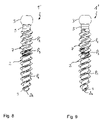
- a second embodiment of the bone screw is shown.
- the bone screw 1' differs from the bone screw only by the thread angles of the first and second sections.
- the second thread angle ⁇ ' is in this case about 80° and the first thread angle ⁇ ' is about 40°.
- the second angle ⁇ ' in this embodiment is about twice the first angle ⁇ '. Such a difference may be useful in the case of known or expected higher pull-out forces that may act on the bone screw.
- a third embodiment of the bone screw is shown.
- the bone screw 1" differs from the bone screw of the previous embodiments only by the thread angle.
- the second angle ⁇ " in the second section P 2 is about 50° and the first angle ⁇ " of the first section P 1 is about 30°.
- This configuration may be useful, for example, in the case of healthy bone for which a reduced insertion torque facilitates the insertion while a risk of pull-out may be not overly high.
- the thread 7 is a double start thread.
- the thread may be a single start thread or a triple or a multiple start thread.
- the bone screw has first and the second sections with the corresponding thread angles as in the previous embodiments.
- thread 7 is shown as a V-thread, other known threadforms can also be used as long as they fulfil the requirement to engage bone.
- threadforms can also be used as long as they fulfil the requirement to engage bone.
- trapezoidal threads, buttress threads, and other threads may be used.
- the specific thread shape, the pitch, the number of threads, etc. are parameters that may depend on the type of bone which the anchor is to be inserted and on the purpose of the bone anchor.
- first section with a first thread angle could be formed adjacent to the tip, followed by a second section with a greater thread angle than that of the first section and further followed by a third section with a greater thread angle than that of the second section in the direction towards the neck.
- pitch and the cross-section of the thread 7 remains substantially the same in the embodiments shown, there may be other embodiments where the pitch is different in the two sections having the different thread angles.
- the shank may also have thread free portions, i.e. the thread 7 may be present only in a portion or portions of the shank.
- the tip 2a needs not to be conical but may be formed by the end surface of a cylindrical shank or can be just any other end portion of the shank that is configured to be inserted into bone first.
- the bone screw may be headless or the head may have another shape.
- Various self-cutting features may also be provided, in particular in the first section and/or the thread may be completely self-cutting.
- polyaxial bone anchoring device all kinds of polyaxial bone anchoring devices may be used.
Landscapes
- Health & Medical Sciences (AREA)
- Orthopedic Medicine & Surgery (AREA)
- Life Sciences & Earth Sciences (AREA)
- Surgery (AREA)
- Neurology (AREA)
- Heart & Thoracic Surgery (AREA)
- Engineering & Computer Science (AREA)
- Biomedical Technology (AREA)
- Nuclear Medicine, Radiotherapy & Molecular Imaging (AREA)
- Medical Informatics (AREA)
- Molecular Biology (AREA)
- Animal Behavior & Ethology (AREA)
- General Health & Medical Sciences (AREA)
- Public Health (AREA)
- Veterinary Medicine (AREA)
- Surgical Instruments (AREA)
Priority Applications (2)
| Application Number | Priority Date | Filing Date | Title |
|---|---|---|---|
| EP21171669.1A EP4082458A1 (de) | 2021-04-30 | 2021-04-30 | Knochenschraube |
| US17/731,088 US20220346848A1 (en) | 2021-04-30 | 2022-04-27 | Bone screw |
Applications Claiming Priority (1)
| Application Number | Priority Date | Filing Date | Title |
|---|---|---|---|
| EP21171669.1A EP4082458A1 (de) | 2021-04-30 | 2021-04-30 | Knochenschraube |
Publications (1)
| Publication Number | Publication Date |
|---|---|
| EP4082458A1 true EP4082458A1 (de) | 2022-11-02 |
Family
ID=75746538
Family Applications (1)
| Application Number | Title | Priority Date | Filing Date |
|---|---|---|---|
| EP21171669.1A Withdrawn EP4082458A1 (de) | 2021-04-30 | 2021-04-30 | Knochenschraube |
Country Status (2)
| Country | Link |
|---|---|
| US (1) | US20220346848A1 (de) |
| EP (1) | EP4082458A1 (de) |
Citations (4)
| Publication number | Priority date | Publication date | Assignee | Title |
|---|---|---|---|---|
| US5120171A (en) | 1990-11-27 | 1992-06-09 | Stuart Surgical | Bone screw with improved threads |
| US20110276095A1 (en) * | 2008-12-09 | 2011-11-10 | Yossef Bar | Double Threaded Orthopedic Screw |
| DE202012002636U1 (de) * | 2011-11-07 | 2013-02-08 | Biomed Est. | Schraubenimplantat für einen Kieferknochen mit koronalem Kompressionsgewinde und apikalem Selbstschneidgewinde |
| US20140121703A1 (en) * | 2012-10-31 | 2014-05-01 | Roger P. Jackson | Polyaxial bone anchor with pop-on multi-thread shank, some with diametric interference fit inserts |
Family Cites Families (1)
| Publication number | Priority date | Publication date | Assignee | Title |
|---|---|---|---|---|
| US8128671B2 (en) * | 2007-04-04 | 2012-03-06 | Warsaw Orthopedic, Inc. | Variable flank bone screw |
-
2021
- 2021-04-30 EP EP21171669.1A patent/EP4082458A1/de not_active Withdrawn
-
2022
- 2022-04-27 US US17/731,088 patent/US20220346848A1/en not_active Abandoned
Patent Citations (4)
| Publication number | Priority date | Publication date | Assignee | Title |
|---|---|---|---|---|
| US5120171A (en) | 1990-11-27 | 1992-06-09 | Stuart Surgical | Bone screw with improved threads |
| US20110276095A1 (en) * | 2008-12-09 | 2011-11-10 | Yossef Bar | Double Threaded Orthopedic Screw |
| DE202012002636U1 (de) * | 2011-11-07 | 2013-02-08 | Biomed Est. | Schraubenimplantat für einen Kieferknochen mit koronalem Kompressionsgewinde und apikalem Selbstschneidgewinde |
| US20140121703A1 (en) * | 2012-10-31 | 2014-05-01 | Roger P. Jackson | Polyaxial bone anchor with pop-on multi-thread shank, some with diametric interference fit inserts |
Also Published As
| Publication number | Publication date |
|---|---|
| US20220346848A1 (en) | 2022-11-03 |
Similar Documents
| Publication | Publication Date | Title |
|---|---|---|
| US6375657B1 (en) | Bonescrew | |
| US8940029B2 (en) | Variable locking bone plating system | |
| EP2517661B1 (de) | Knochenschraube | |
| EP2887897B1 (de) | Orthopädische befestigungsvorrichtung | |
| US9198702B2 (en) | Bone screw | |
| US20050228388A1 (en) | Double lead bone screw | |
| EP2887898B1 (de) | Verfahren zur erstellung eines orthopädisches befestigungselement | |
| US20140012335A1 (en) | Bone screw and method of manufacturing same | |
| EP3758631B1 (de) | Knochenbefestigungselement mit teilweise überlappenden gewinden und einer variierenden gewindesteigung | |
| EP2614787A1 (de) | Mehrachsige Knochenplattenfixierung | |
| US20040243129A1 (en) | Double helical threaded bone screw | |
| US20110137354A1 (en) | Bone screw | |
| US8419779B2 (en) | Systematic displacement bone screw | |
| US20220323131A1 (en) | Fastening devices, systems, and methods | |
| EP4082458A1 (de) | Knochenschraube | |
| US20230248408A1 (en) | Bone anchor | |
| EP4052672A1 (de) | Knochenanker | |
| US20240099751A1 (en) | Orthopedic bone screw | |
| CN116600730A (zh) | 包括具有至少两个骨螺纹的椎弓根螺钉的脊柱骨紧固件组件 |
Legal Events
| Date | Code | Title | Description |
|---|---|---|---|
| PUAI | Public reference made under article 153(3) epc to a published international application that has entered the european phase |
Free format text: ORIGINAL CODE: 0009012 |
|
| STAA | Information on the status of an ep patent application or granted ep patent |
Free format text: STATUS: REQUEST FOR EXAMINATION WAS MADE |
|
| 17P | Request for examination filed |
Effective date: 20211229 |
|
| AK | Designated contracting states |
Kind code of ref document: A1 Designated state(s): AL AT BE BG CH CY CZ DE DK EE ES FI FR GB GR HR HU IE IS IT LI LT LU LV MC MK MT NL NO PL PT RO RS SE SI SK SM TR |
|
| STAA | Information on the status of an ep patent application or granted ep patent |
Free format text: STATUS: THE APPLICATION HAS BEEN WITHDRAWN |
|
| 18W | Application withdrawn |
Effective date: 20221222 |