EP4082443A1 - Ultrasound diagnostic apparatus and method for operating same - Google Patents
Ultrasound diagnostic apparatus and method for operating same Download PDFInfo
- Publication number
- EP4082443A1 EP4082443A1 EP20926960.4A EP20926960A EP4082443A1 EP 4082443 A1 EP4082443 A1 EP 4082443A1 EP 20926960 A EP20926960 A EP 20926960A EP 4082443 A1 EP4082443 A1 EP 4082443A1
- Authority
- EP
- European Patent Office
- Prior art keywords
- nerve
- region
- abnormal
- basis
- target
- Prior art date
- Legal status (The legal status is an assumption and is not a legal conclusion. Google has not performed a legal analysis and makes no representation as to the accuracy of the status listed.)
- Pending
Links
- 238000002604 ultrasonography Methods 0.000 title claims abstract description 386
- 238000000034 method Methods 0.000 title claims abstract description 58
- 210000005036 nerve Anatomy 0.000 claims abstract description 500
- 230000002159 abnormal effect Effects 0.000 claims abstract description 234
- 239000000523 sample Substances 0.000 claims description 20
- 230000002093 peripheral effect Effects 0.000 claims description 12
- 210000003484 anatomy Anatomy 0.000 claims description 10
- 230000015654 memory Effects 0.000 claims description 10
- 238000004590 computer program Methods 0.000 claims description 3
- 241000264877 Hippospongia communis Species 0.000 description 154
- 230000005856 abnormality Effects 0.000 description 26
- 238000012545 processing Methods 0.000 description 12
- 238000004891 communication Methods 0.000 description 11
- 238000013528 artificial neural network Methods 0.000 description 6
- 230000011218 segmentation Effects 0.000 description 5
- 238000001514 detection method Methods 0.000 description 4
- 238000010586 diagram Methods 0.000 description 4
- 230000005484 gravity Effects 0.000 description 4
- 230000004044 response Effects 0.000 description 4
- 230000005540 biological transmission Effects 0.000 description 2
- 238000006243 chemical reaction Methods 0.000 description 2
- 238000002591 computed tomography Methods 0.000 description 2
- 230000033001 locomotion Effects 0.000 description 2
- 241001465754 Metazoa Species 0.000 description 1
- 238000003491 array Methods 0.000 description 1
- 230000017531 blood circulation Effects 0.000 description 1
- 239000003086 colorant Substances 0.000 description 1
- 230000007423 decrease Effects 0.000 description 1
- 238000002059 diagnostic imaging Methods 0.000 description 1
- 230000000694 effects Effects 0.000 description 1
- 230000006870 function Effects 0.000 description 1
- 238000003384 imaging method Methods 0.000 description 1
- 230000001788 irregular Effects 0.000 description 1
- 238000002595 magnetic resonance imaging Methods 0.000 description 1
- 238000012986 modification Methods 0.000 description 1
- 230000004048 modification Effects 0.000 description 1
- 230000003287 optical effect Effects 0.000 description 1
- 210000000056 organ Anatomy 0.000 description 1
- 230000003252 repetitive effect Effects 0.000 description 1
- 210000004872 soft tissue Anatomy 0.000 description 1
- 238000012549 training Methods 0.000 description 1
- 238000012285 ultrasound imaging Methods 0.000 description 1
Images


Classifications
-
- A—HUMAN NECESSITIES
- A61—MEDICAL OR VETERINARY SCIENCE; HYGIENE
- A61B—DIAGNOSIS; SURGERY; IDENTIFICATION
- A61B8/00—Diagnosis using ultrasonic, sonic or infrasonic waves
- A61B8/46—Ultrasonic, sonic or infrasonic diagnostic devices with special arrangements for interfacing with the operator or the patient
- A61B8/467—Ultrasonic, sonic or infrasonic diagnostic devices with special arrangements for interfacing with the operator or the patient characterised by special input means
- A61B8/468—Ultrasonic, sonic or infrasonic diagnostic devices with special arrangements for interfacing with the operator or the patient characterised by special input means allowing annotation or message recording
-
- A—HUMAN NECESSITIES
- A61—MEDICAL OR VETERINARY SCIENCE; HYGIENE
- A61B—DIAGNOSIS; SURGERY; IDENTIFICATION
- A61B8/00—Diagnosis using ultrasonic, sonic or infrasonic waves
- A61B8/08—Detecting organic movements or changes, e.g. tumours, cysts, swellings
- A61B8/0833—Detecting organic movements or changes, e.g. tumours, cysts, swellings involving detecting or locating foreign bodies or organic structures
- A61B8/085—Detecting organic movements or changes, e.g. tumours, cysts, swellings involving detecting or locating foreign bodies or organic structures for locating body or organic structures, e.g. tumours, calculi, blood vessels, nodules
-
- A—HUMAN NECESSITIES
- A61—MEDICAL OR VETERINARY SCIENCE; HYGIENE
- A61B—DIAGNOSIS; SURGERY; IDENTIFICATION
- A61B8/00—Diagnosis using ultrasonic, sonic or infrasonic waves
- A61B8/46—Ultrasonic, sonic or infrasonic diagnostic devices with special arrangements for interfacing with the operator or the patient
- A61B8/461—Displaying means of special interest
- A61B8/463—Displaying means of special interest characterised by displaying multiple images or images and diagnostic data on one display
-
- A—HUMAN NECESSITIES
- A61—MEDICAL OR VETERINARY SCIENCE; HYGIENE
- A61B—DIAGNOSIS; SURGERY; IDENTIFICATION
- A61B8/00—Diagnosis using ultrasonic, sonic or infrasonic waves
- A61B8/52—Devices using data or image processing specially adapted for diagnosis using ultrasonic, sonic or infrasonic waves
- A61B8/5215—Devices using data or image processing specially adapted for diagnosis using ultrasonic, sonic or infrasonic waves involving processing of medical diagnostic data
- A61B8/5223—Devices using data or image processing specially adapted for diagnosis using ultrasonic, sonic or infrasonic waves involving processing of medical diagnostic data for extracting a diagnostic or physiological parameter from medical diagnostic data
-
- G—PHYSICS
- G06—COMPUTING; CALCULATING OR COUNTING
- G06N—COMPUTING ARRANGEMENTS BASED ON SPECIFIC COMPUTATIONAL MODELS
- G06N20/00—Machine learning
-
- G—PHYSICS
- G06—COMPUTING; CALCULATING OR COUNTING
- G06T—IMAGE DATA PROCESSING OR GENERATION, IN GENERAL
- G06T7/00—Image analysis
- G06T7/0002—Inspection of images, e.g. flaw detection
- G06T7/0012—Biomedical image inspection
- G06T7/0014—Biomedical image inspection using an image reference approach
- G06T7/0016—Biomedical image inspection using an image reference approach involving temporal comparison
-
- G—PHYSICS
- G16—INFORMATION AND COMMUNICATION TECHNOLOGY [ICT] SPECIALLY ADAPTED FOR SPECIFIC APPLICATION FIELDS
- G16H—HEALTHCARE INFORMATICS, i.e. INFORMATION AND COMMUNICATION TECHNOLOGY [ICT] SPECIALLY ADAPTED FOR THE HANDLING OR PROCESSING OF MEDICAL OR HEALTHCARE DATA
- G16H30/00—ICT specially adapted for the handling or processing of medical images
- G16H30/20—ICT specially adapted for the handling or processing of medical images for handling medical images, e.g. DICOM, HL7 or PACS
-
- G—PHYSICS
- G16—INFORMATION AND COMMUNICATION TECHNOLOGY [ICT] SPECIALLY ADAPTED FOR SPECIFIC APPLICATION FIELDS
- G16H—HEALTHCARE INFORMATICS, i.e. INFORMATION AND COMMUNICATION TECHNOLOGY [ICT] SPECIALLY ADAPTED FOR THE HANDLING OR PROCESSING OF MEDICAL OR HEALTHCARE DATA
- G16H30/00—ICT specially adapted for the handling or processing of medical images
- G16H30/40—ICT specially adapted for the handling or processing of medical images for processing medical images, e.g. editing
-
- G—PHYSICS
- G16—INFORMATION AND COMMUNICATION TECHNOLOGY [ICT] SPECIALLY ADAPTED FOR SPECIFIC APPLICATION FIELDS
- G16H—HEALTHCARE INFORMATICS, i.e. INFORMATION AND COMMUNICATION TECHNOLOGY [ICT] SPECIALLY ADAPTED FOR THE HANDLING OR PROCESSING OF MEDICAL OR HEALTHCARE DATA
- G16H40/00—ICT specially adapted for the management or administration of healthcare resources or facilities; ICT specially adapted for the management or operation of medical equipment or devices
- G16H40/60—ICT specially adapted for the management or administration of healthcare resources or facilities; ICT specially adapted for the management or operation of medical equipment or devices for the operation of medical equipment or devices
- G16H40/67—ICT specially adapted for the management or administration of healthcare resources or facilities; ICT specially adapted for the management or operation of medical equipment or devices for the operation of medical equipment or devices for remote operation
-
- G—PHYSICS
- G16—INFORMATION AND COMMUNICATION TECHNOLOGY [ICT] SPECIALLY ADAPTED FOR SPECIFIC APPLICATION FIELDS
- G16H—HEALTHCARE INFORMATICS, i.e. INFORMATION AND COMMUNICATION TECHNOLOGY [ICT] SPECIALLY ADAPTED FOR THE HANDLING OR PROCESSING OF MEDICAL OR HEALTHCARE DATA
- G16H50/00—ICT specially adapted for medical diagnosis, medical simulation or medical data mining; ICT specially adapted for detecting, monitoring or modelling epidemics or pandemics
- G16H50/20—ICT specially adapted for medical diagnosis, medical simulation or medical data mining; ICT specially adapted for detecting, monitoring or modelling epidemics or pandemics for computer-aided diagnosis, e.g. based on medical expert systems
-
- G—PHYSICS
- G16—INFORMATION AND COMMUNICATION TECHNOLOGY [ICT] SPECIALLY ADAPTED FOR SPECIFIC APPLICATION FIELDS
- G16H—HEALTHCARE INFORMATICS, i.e. INFORMATION AND COMMUNICATION TECHNOLOGY [ICT] SPECIALLY ADAPTED FOR THE HANDLING OR PROCESSING OF MEDICAL OR HEALTHCARE DATA
- G16H50/00—ICT specially adapted for medical diagnosis, medical simulation or medical data mining; ICT specially adapted for detecting, monitoring or modelling epidemics or pandemics
- G16H50/70—ICT specially adapted for medical diagnosis, medical simulation or medical data mining; ICT specially adapted for detecting, monitoring or modelling epidemics or pandemics for mining of medical data, e.g. analysing previous cases of other patients
-
- A—HUMAN NECESSITIES
- A61—MEDICAL OR VETERINARY SCIENCE; HYGIENE
- A61B—DIAGNOSIS; SURGERY; IDENTIFICATION
- A61B8/00—Diagnosis using ultrasonic, sonic or infrasonic waves
- A61B8/44—Constructional features of the ultrasonic, sonic or infrasonic diagnostic device
- A61B8/4405—Device being mounted on a trolley
-
- A—HUMAN NECESSITIES
- A61—MEDICAL OR VETERINARY SCIENCE; HYGIENE
- A61B—DIAGNOSIS; SURGERY; IDENTIFICATION
- A61B8/00—Diagnosis using ultrasonic, sonic or infrasonic waves
- A61B8/44—Constructional features of the ultrasonic, sonic or infrasonic diagnostic device
- A61B8/4427—Device being portable or laptop-like
-
- A—HUMAN NECESSITIES
- A61—MEDICAL OR VETERINARY SCIENCE; HYGIENE
- A61B—DIAGNOSIS; SURGERY; IDENTIFICATION
- A61B8/00—Diagnosis using ultrasonic, sonic or infrasonic waves
- A61B8/46—Ultrasonic, sonic or infrasonic diagnostic devices with special arrangements for interfacing with the operator or the patient
- A61B8/461—Displaying means of special interest
- A61B8/464—Displaying means of special interest involving a plurality of displays
-
- G—PHYSICS
- G06—COMPUTING; CALCULATING OR COUNTING
- G06N—COMPUTING ARRANGEMENTS BASED ON SPECIFIC COMPUTATIONAL MODELS
- G06N3/00—Computing arrangements based on biological models
- G06N3/02—Neural networks
- G06N3/04—Architecture, e.g. interconnection topology
- G06N3/0499—Feedforward networks
-
- G—PHYSICS
- G06—COMPUTING; CALCULATING OR COUNTING
- G06T—IMAGE DATA PROCESSING OR GENERATION, IN GENERAL
- G06T2200/00—Indexing scheme for image data processing or generation, in general
- G06T2200/24—Indexing scheme for image data processing or generation, in general involving graphical user interfaces [GUIs]
-
- G—PHYSICS
- G06—COMPUTING; CALCULATING OR COUNTING
- G06T—IMAGE DATA PROCESSING OR GENERATION, IN GENERAL
- G06T2207/00—Indexing scheme for image analysis or image enhancement
- G06T2207/10—Image acquisition modality
- G06T2207/10016—Video; Image sequence
-
- G—PHYSICS
- G06—COMPUTING; CALCULATING OR COUNTING
- G06T—IMAGE DATA PROCESSING OR GENERATION, IN GENERAL
- G06T2207/00—Indexing scheme for image analysis or image enhancement
- G06T2207/10—Image acquisition modality
- G06T2207/10132—Ultrasound image
-
- G—PHYSICS
- G06—COMPUTING; CALCULATING OR COUNTING
- G06T—IMAGE DATA PROCESSING OR GENERATION, IN GENERAL
- G06T2207/00—Indexing scheme for image analysis or image enhancement
- G06T2207/10—Image acquisition modality
- G06T2207/10132—Ultrasound image
- G06T2207/10136—3D ultrasound image
-
- G—PHYSICS
- G06—COMPUTING; CALCULATING OR COUNTING
- G06T—IMAGE DATA PROCESSING OR GENERATION, IN GENERAL
- G06T2207/00—Indexing scheme for image analysis or image enhancement
- G06T2207/20—Special algorithmic details
- G06T2207/20081—Training; Learning
-
- G—PHYSICS
- G06—COMPUTING; CALCULATING OR COUNTING
- G06T—IMAGE DATA PROCESSING OR GENERATION, IN GENERAL
- G06T2207/00—Indexing scheme for image analysis or image enhancement
- G06T2207/20—Special algorithmic details
- G06T2207/20084—Artificial neural networks [ANN]
-
- G—PHYSICS
- G06—COMPUTING; CALCULATING OR COUNTING
- G06T—IMAGE DATA PROCESSING OR GENERATION, IN GENERAL
- G06T2207/00—Indexing scheme for image analysis or image enhancement
- G06T2207/30—Subject of image; Context of image processing
- G06T2207/30004—Biomedical image processing
Definitions
- the present invention relates to an ultrasound diagnostic apparatus and a method for operating the same.
- the present invention is directed to determining whether an abnormality is present in a nerve region detected from an ultrasound image, and on the basis of the determination result, providing information about an abnormal region of the nerve region or basis information about a basis for determining the abnormal region.
- a method for operating an ultrasound diagnostic apparatus including acquiring a first ultrasound image of an object, detecting a first nerve region corresponding to a first target nerve in the first ultrasound image, determining whether an abnormal region is present in the first nerve region of the first ultrasound image on the basis of a determination standard for determining whether a target nerve is abnormal, and displaying at least one of information about the abnormal region and basis information about a basis for determining the abnormal region on the basis of a result of determining whether the abnormal region is present in the first nerve region.
- an ultrasound diagnostic apparatus including a probe configured to transmit an ultrasound signal to an object and receive an ultrasound signal reflected from the object, a user interface device, a display, a processor, and a memory configured to store instructions executable by the processor, wherein, the processor executes the instructions to acquire a first ultrasound image of the object on the basis of the reflected ultrasound signal, detect a first nerve region corresponding to a first target nerve in the first ultrasound image, determine whether an abnormal region is present in the first nerve region of the first ultrasound image on the basis of a determination standard for determining whether a target nerve is abnormal, and display at least one of information about the abnormal region and basis information about a basis for determining the abnormal region through the display on the basis of a result of determining whether the abnormal region is present in the first nerve region.
- Disclosed is a method for operating an ultrasound diagnostic apparatus including acquiring a first ultrasound image of an object, detecting a first nerve region corresponding to a first target nerve in the first ultrasound image, determining whether an abnormal region is present in the first nerve region of the first ultrasound image on the basis of a determination standard for determining whether a target nerve is abnormal, and displaying at least one of information about the abnormal region and basis information about a basis for determining the abnormal region on the basis of a result of determining whether the abnormal region is present in the first nerve region.
- an image may include a medical image acquired by a medical imaging apparatus such as a magnetic resonance imaging (MRI) apparatus, a computed tomography (CT) apparatus, an ultrasound imaging apparatus, and an X-ray imaging apparatus.
- MRI magnetic resonance imaging
- CT computed tomography
- ultrasound imaging apparatus an ultrasound imaging apparatus
- X-ray imaging apparatus an X-ray imaging apparatus
- ultrasound image refers to an image of an object, which is processed on the basis of an ultrasound signal transmitted to the object and reflected from the object.
- target nerve refers to a nerve that is a target for determining whether there is an abnormality
- target nerve region refers to a region corresponding to the target nerve in an ultrasound image.
- the target nerve is a nerve of the same type as a reference nerve and refers to a nerve to be examined or diagnosed.
- reference nerve refers to a nerve that becomes a reference for determining whether an abnormality is present in a target nerve
- reference nerve region refers to a region corresponding to the reference nerve in an ultrasound image
- FIG. 1 is a block diagram illustrating a configuration of an ultrasound diagnostic apparatus 100 according to one embodiment.
- the ultrasound diagnostic apparatus 100 may include a probe 20, an ultrasound transceiver 110, a controller 120, an image processor 130, a display part 140, a storage part 150, a communication part 160, and an input part 170.
- the probe 20 may include a plurality of transducers.
- the plurality of transducers may transmit an ultrasound signal to an object 10 according to a transmission signal applied from a transmitter 113.
- the plurality of transducers may receive the ultrasound signal reflected from the object 10 and form a received signal.
- the probe 20 may be implemented integrally with the ultrasound diagnostic apparatus 100 or may be implemented as a separate type connected to the ultrasound diagnostic apparatus 100 in a wired or wireless manner.
- the ultrasound diagnostic apparatus 100 may be provided with one or a plurality of probes 20 depending on an implementation form.
- the controller 120 controls the transmitter 113 to form the transmission signal to be applied to each of the plurality of transducers in consideration of positions and focal points of the plurality of transducers included in the probe 20.
- the controller 120 converts the received signal received from the probe 20 in an analog-to-digital conversion manner, and controls a receiver 115 to generate ultrasound data by summing the digitally converted received signals in consideration of the positions and focal points of the plurality of transducers.
- the image processor 130 generates an ultrasound image using the ultrasound data generated by the receiver 115.
- the display part 140 may display the generated ultrasound image and various pieces of information processed by the ultrasound diagnostic apparatus 100.
- the ultrasound diagnostic apparatus 100 may include one or a plurality of display parts 140 depending on the implementation form.
- the display part 140 may be implemented as a touch screen in combination with a touch panel.
- the controller 120 may control the overall operation of the ultrasound diagnostic apparatus 100 and a signal flow between internal components of the ultrasound diagnostic apparatus 100.
- the controller 120 may include a memory that stores a program or data for performing a function of the ultrasound diagnostic apparatus 100, and a processor that processes the program or data.
- the controller 120 may control the operation of the ultrasound diagnostic apparatus 100 by receiving a control signal from the input part 170 or an external apparatus.
- the ultrasound diagnostic apparatus 100 includes the communication part 160, and may be connected to the external apparatus (for example, a server, a medical apparatus, a portable apparatus (smart phone, tablet PC, wearable device, and the like) through the communication part 160.
- the external apparatus for example, a server, a medical apparatus, a portable apparatus (smart phone, tablet PC, wearable device, and the like)
- the communication part 160 may receive a control signal and data from the external apparatus and transmit the received control signal to the controller 120 so that the controller 120 may control the ultrasound diagnostic apparatus 100 in response to the received control signal.
- the controller 120 may transmit a control signal to the external apparatus through the communication part 160 so that the external apparatus may be controlled in response to the control signal of the controller 120.
- the external apparatus may process data of an external apparatus in response to the control signal of the controller received through the communication part.
- a program capable of controlling the ultrasound diagnostic apparatus 100 may be installed in the external apparatus, and the program may include instructions for performing some or all of the operations of the controller 120.
- the program may be installed in the external apparatus in advance or may be installed by a user of the external apparatus by downloading the program from a server that provides applications.
- the server that provides applications may include a recording medium in which the corresponding program is stored.
- the storage part 150 may store various types of data or programs for driving and controlling the ultrasound diagnostic apparatus 100, input/output ultrasound data, acquired ultrasound images, and the like.
- the input part 170 may receive a user's input for controlling the ultrasound diagnostic apparatus 100.
- the user's input may include an input for manipulating a button, a keypad, a mouse, a trackball, a j og switch, a knob, or the like, an input for touching a touchpad or a touch screen, a voice input, a motion input, and a biometric information input (e.g., iris recognition, fingerprint recognition, or the like), but the present invention is not limited thereto.
- FIGS. 2A to 2C are views illustrating ultrasound diagnostic apparatuses according to one embodiment.
- the button, the trackball, the jog switch, the knob, or the like included in the control panel 165 may be provided to the GUI on the main display part 121 or the sub-display part 122.
- the ultrasound diagnostic apparatus 100c may include a probe 20 and a main body 40, and the probe 20 may be connected to one side of the main body 40 in a wired or wireless manner.
- the main body 40 may include a touch screen 145.
- the touch screen 145 may display ultrasound images, various pieces of information processed by the ultrasound diagnostic apparatus, a GUI, and the like.
- FIG. 3 is a view for schematically describing a process of detecting a nerve region of a target nerve in an ultrasound image to determine whether there is an abnormality, and displaying the determination result, according to one embodiment.
- the ultrasound diagnostic apparatus 100 may acquire an ultrasound image of an object.
- the ultrasound image may be an image obtained by scanning a target nerve, and may include a nerve region corresponding to the target nerve.
- the ultrasound diagnostic apparatus 100 may display the ultrasound image on a display of the ultrasound diagnostic apparatus 100.
- the ultrasound diagnostic apparatus 100 may detect a nerve region corresponding to the target nerve in the ultrasound image on the basis of an algorithm for detecting the nerve region. As shown in an image 321, the ultrasound diagnostic apparatus 100 may display a nerve region 322 in the ultrasound image.
- the ultrasound diagnostic apparatus 100 may detect the first nerve region corresponding to the first target nerve in the first ultrasound image on the basis of a predetermined automatic detection algorithm or a predetermined automatic segmentation algorithm.
- the ultrasound diagnostic apparatus 100 may display the detected first nerve region on the first ultrasound image.
- the ultrasound diagnostic apparatus 100 may display only the detected first nerve region. A process of detecting the nerve region from the ultrasound image will be described with reference to FIG. 5 .
- the ultrasound diagnostic apparatus 100 may determine whether an abnormal region is present in the first nerve region of the first ultrasound image on the basis of the determination standard for determining whether a target nerve is abnormal.
- the determination standard may be acquired on the basis of at least one of an anatomical structure in a reference nerve region for a reference nerve, a shape of the reference nerve region, and a size of the reference nerve region.
- the anatomical structure may be determined on the basis of the shape, size, and relative positional relationship of structures constituting the nerve.
- the ultrasound diagnostic apparatus 100 may determine whether an abnormality is present in the first target nerve on the basis of a honeycomb structure that is an anatomical structure observed in a first target nerve region. Specifically, the ultrasound diagnostic apparatus 100 may determine whether an abnormal region is present in the first nerve region corresponding to the first target nerve on the basis of a similarity between a reference honeycomb structure in the reference nerve region for the reference nerve and a target honeycomb structure in a target nerve region for the target nerve. A process of determining whether the nerve is abnormal on the basis of the honeycomb structure observed in the ultrasound image will be described with reference to FIG. 6 .
- the learning model may be a model in which the reference honeycomb structure is learned on the basis of at least one of a shape and pattern of a honeycomb structure included in a plurality of ultrasound images and a structure of a peripheral region of the honeycomb structure.
- the learning model may be a model for determining whether a predetermined target nerve is abnormal when an ultrasound image in which a target honeycomb structure is included in the predetermined target nerve is acquired.
- the ultrasound diagnostic apparatus 100 may acquire the similarity on the basis of at least one of corner information and feature point information for each of the reference honeycomb structure in the reference nerve region for the reference nerve and the first target honeycomb structure in the first nerve region.
- the ultrasound diagnostic apparatus 100 may determine whether an abnormal region is present in the first nerve region corresponding to the first target nerve on the basis of the acquired similarity.
- the ultrasound diagnostic apparatus 100 may determine whether an abnormal region is present in the first nerve region corresponding to the first target nerve on the basis of a third determination standard for determining whether a target nerve is abnormal using a difference between a size of a reference cross-sectional area of the reference nerve region for the reference nerve and a size of a cross-sectional area of the target nerve region for the target nerve.
- a process of determining whether the target nerve is abnormal on the basis of the size of the cross-sectional area of the target nerve region will be described with reference to FIG. 8 .
- the ultrasound diagnostic apparatus 100 may acquire a reference value of at least one parameter, which becomes a reference for determining whether the target nerve is abnormal.
- the parameter may include at least one of Validity of the honeycomb structure observed in the nerve region, the similarity of the honeycomb structure, the shape of the nerve region, the aspect ratio of the nerve region, and the size of the cross-sectional area of the nerve region, and the present invention is not limited to the above examples.
- the ultrasound diagnostic apparatus 100 may determine that an abnormal region is present in the first nerve region when a difference between a value of at least one parameter acquired from the first ultrasound image and the reference value of at least one parameter is out of a preset range.
- the basis information about the basis for determining the abnormal region may include information about at least one parameter, which becomes a reference for determining whether the first target nerve is abnormal, and information obtained by comparing the value of at least one parameter and the reference value of at least one parameter.
- the ultrasound diagnostic apparatus 100 may display the information about the abnormal region on the first ultrasound image.
- the ultrasound diagnostic apparatus 100 may display trend information of the abnormal region for the object by referring to a previous ultrasound image for the object.
- FIG. 5 is a view for describing a process of detecting a nerve region from an ultrasound image and displaying an abnormal region in the ultrasound image, according to one embodiment.
- the ultrasound diagnostic apparatus 100 may acquire a first ultrasound image for a first target nerve.
- An image 510 of FIG. 5 represents the first ultrasound image for the first target nerve.
- the ultrasound diagnostic apparatus 100 may acquire the first ultrasound image in real time using the probe in the ultrasound diagnostic apparatus 100, or acquire the first ultrasound image from ultrasound images stored in the ultrasound diagnostic apparatus 100.
- the ultrasound diagnostic apparatus 100 may receive the first ultrasound image from the external apparatus.
- the ultrasound diagnostic apparatus 100 may detect a first nerve region corresponding to the first target nerve in the first ultrasound image.
- the ultrasound diagnostic apparatus 100 may analyze the entire region of the first ultrasound image and detect the first nerve region corresponding to the first target nerve using a predetermined automatic detection algorithm.
- the predetermined automatic detection algorithm may be a learning model that detects a nerve region corresponding to a target nerve in an ultrasound image.
- An image 520 of FIG. 5 represents an image in which a region 521 detected as the first nerve region is displayed on the first ultrasound image.
- the first nerve region may be automatically tracked according to the changed cross-section, and the first nerve region may be displayed.
- the ultrasound diagnostic apparatus 100 may track and display only the detected first nerve region. For example, the ultrasound diagnostic apparatus 100 may display the first nerve region with a bounding box as shown in the image 520 of FIG. 5 . Here, a strength of a boundary represented by the bounding box may be adjusted.
- the ultrasound diagnostic apparatus 100 may detect the first nerve region corresponding to the first target nerve by segmenting the first ultrasound image into a plurality of regions using a predetermined automatic segmentation algorithm and analyzing the entire segmented plurality of regions.
- the predetermined automatic segmentation algorithm may be a learning model for detecting a nerve region corresponding to a target nerve by segmenting an ultrasound image into a plurality of regions and analyzing the segmented regions.
- An image 530 of FIG. 5 represents an image in which a region 531 detected as the first nerve region is displayed on the first ultrasound image.
- the ultrasound diagnostic apparatus 100 may precisely detect the region 531 in the first nerve region by analyzing the region 521 detected as the first nerve region from the image 520 of FIG. 5 on the basis of the predetermined automatic segmentation algorithm.
- the first nerve region corresponding to the first target nerve may also be determined in the first ultrasound image on the basis of a user's input.
- the ultrasound diagnostic apparatus 100 may determine whether an abnormal region is present in the first nerve region of the first ultrasound image on the basis of a determination standard for determining whether a target nerve is abnormal. When it is determined that the abnormal region is present in the first nerve region, the ultrasound diagnostic apparatus 100 may detect the abnormal region in the first nerve region and display the abnormal region.
- An image 540 of FIG. 5 represents an image in which an abnormal region 541 in the first nerve region is displayed on the first ultrasound image.
- FIG. 6 is a view for describing a process of determining whether a nerve is abnormal on the basis of an anatomical structure in a nerve region in an ultrasound image, according to one embodiment.
- the ultrasound diagnostic apparatus 100 may determine whether an abnormal region is present in the first nerve region of the first ultrasound image on the basis of a determination standard for determining whether a target nerve is abnormal, which is acquired on the basis of the anatomical structure in a reference nerve region for a reference nerve.
- the ultrasound diagnostic apparatus 100 may determine whether an abnormal region is present in the first nerve region of the first ultrasound image on the basis of a first determination standard for determining whether a target nerve is abnormal using a honeycomb structure representing a structure observed in a nerve region.
- the first determination standard may be a reference for determining whether a target nerve is abnormal using a similarity between a reference honeycomb structure in the reference nerve region and a target honeycomb structure in the target nerve region.
- the reference honeycomb structure represents a structure observed in the reference nerve region.
- the reference honeycomb structure may also be a structure that is observed in a nerve region of a normal nerve.
- the similarity may indicate a matching rate between the reference honeycomb structure and the target honeycomb structure.
- the similarity between the reference honeycomb structure and the target honeycomb structure may be acquired on the basis of at least one of a learning model, template matching, information about a feature point, and corner information.
- the ultrasound diagnostic apparatus 100 may acquire the learning model for determining whether a target nerve is abnormal using the similarity between the reference honeycomb structure and the target honeycomb structure.
- the ultrasound diagnostic apparatus 100 may acquire the similarity between the reference honeycomb structure and the first target honeycomb structure in the first nerve region by applying the first nerve region to the learning model.
- the learning model for acquiring the similarity between the reference honeycomb structure and the target honeycomb structure and determining whether the target nerve is abnormal using the similarity will be described with reference to FIGS. 9A and 9B .
- the ultrasound diagnostic apparatus 100 may acquire the similarity on the basis of a matching rate between the reference honeycomb structure in the reference nerve region of a reference template for the reference nerve and the first target honeycomb structure in the first nerve region.
- the ultrasound diagnostic apparatus 100 may store a plurality of reference templates for the reference nerve.
- the ultrasound diagnostic apparatus 100 may detect the first target honeycomb structure in the first nerve region of the first ultrasound image.
- the ultrasound diagnostic apparatus 100 may acquire a first reference honeycomb structure having a structure most similar to the first target honeycomb structure by comparing the reference honeycomb structure of each of the plurality of reference templates with the first target honeycomb structure.
- the ultrasound diagnostic apparatus 100 may acquire the similarity indicating the matching rate between the first reference honeycomb structure and the first target honeycomb structure on the basis of the shape or pattern of the first target honeycomb structure and the first reference honeycomb structure.
- the ultrasound diagnostic apparatus 100 may acquire information about the feature points, which includes at least one piece of information about the number, a location, a distribution degree, a maximum brightness value, a minimum brightness value, and an average value of brightness values of the feature points corresponding to the reference feature points.
- the ultrasound diagnostic apparatus 100 may compare values of at least one parameter on the basis of the information about the reference feature points and the information about the feature points, and acquire the similarity on the basis of the comparison result. A process of acquiring the similarity using the corner information and determining whether a target nerve is abnormal according to the similarity will be described with reference to FIG. 10 .
- the ultrasound diagnostic apparatus 100 may determine that the first target nerve is normal.
- An image 610 of FIG. 6 is a view illustrating a normal first target honeycomb structure 611 observed in the first nerve region corresponding to the first target nerve.
- the ultrasound diagnostic apparatus 100 may determine that an abnormality is present in the first target nerve.
- the ultrasound diagnostic apparatus 100 may detect a region, in which an abnormal honeycomb structure exists, in the first nerve region corresponding to the first target nerve on the basis of the learning model.
- An image 620 of FIG. 6 is a view illustrating an abnormal first target honeycomb structure 621 observed in the first nerve region corresponding to the first target nerve. Honeycomb structures observed in normal nerves and honeycomb structures observed in abnormal nerves will be described with reference to FIG. 9C .
- FIG. 7 is a view for describing a process of determining whether a nerve is abnormal on the basis of a shape of a nerve region in an ultrasound image, according to one embodiment.
- An image 720 of FIG. 7 is a view for describing a method of detecting a major axis in a nerve region 721.
- the ultrasound diagnostic apparatus 100 may detect a center of gravity in the nerve region 721.
- the ultrasound diagnostic apparatus 100 may detect a line segment 722, which is the longest among line segments each having intersecting points between a straight line passing through the center of gravity of the nerve region 721 and the nerve region 721 as both end points, as the major axis.
- An image 730 of FIG. 7 is a view for describing a method of detecting a minor axis in a nerve region 731.
- the ultrasound diagnostic apparatus 100 may detect a center of gravity in the nerve region 731.
- the ultrasound diagnostic apparatus 100 may detect a line segment 732, which is the shortest among line segments each having intersecting points between a straight line passing through the center of gravity of the nerve region 731 and the nerve region 731 as both end points, as the minor axis.
- the ultrasound diagnostic apparatus 100 may acquire the reference aspect ratio of the reference nerve region for the reference nerve.
- the reference aspect ratio may be set by the user or acquired from the external apparatus.
- the ultrasound diagnostic apparatus 100 may acquire the first ultrasound image for the first target nerve and detect the first nerve region corresponding to the first target nerve from the first ultrasound image.
- the ultrasound diagnostic apparatus 100 may acquire a length of a major axis and a length of a minor axis for the first nerve region.
- the ultrasound diagnostic apparatus 100 may calculate an aspect ratio representing a ratio of the length of the major axis to the length of the minor axis. When a difference between the reference aspect ratio and the aspect ratio is within a preset range, the ultrasound diagnostic apparatus 100 may determine that the first target nerve is normal.
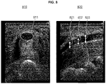
- FIG. 8 is a view for describing a process of determining whether a nerve is abnormal on the basis of a size of a cross-sectional area of a nerve region in an ultrasound image, according to one embodiment.
- the ultrasound diagnostic apparatus 100 may determine whether an abnormal region is present in a first nerve region corresponding to the first target nerve on the basis of a third determination standard for determining whether a target nerve is abnormal using a difference between a size of a cross-sectional area of a reference nerve region for a reference nerve and a size of a cross-sectional area of a target nerve region for the target nerve.
- a size of a cross-sectional area of the nerve may be less than a size of a reference cross-sectional area.
- the size of the reference cross-sectional area may be a threshold value that becomes a reference to determine that a nerve is normal.
- the size of the reference cross-sectional area for the reference nerve may be set by the user or acquired from the external apparatus.
- the ultrasound diagnostic apparatus 100 may acquire a first ultrasound image for the first target nerve and detect a first nerve region 811 corresponding to the first target nerve from the first ultrasound image.
- the ultrasound diagnostic apparatus 100 may calculate a size of a cross-sectional area of the first nerve region 811.
- the ultrasound diagnostic apparatus 100 may determine that the first target nerve 811 is normal.
- the ultrasound diagnostic apparatus 100 may determine that an abnormality is present in the first target nerve. That is, the ultrasound diagnostic apparatus 100 may determine the first nerve region 811, in which the size of the cross-sectional area is calculated, as the abnormal region.
- the ultrasound diagnostic apparatus 100 may calculate a size of a cross-sectional area for each of the plurality of nerve regions, and detect an abnormal nerve region on the basis of the result of comparison between the calculated size of the cross-sectional area and the size of the reference cross-sectional area.
- the ultrasound diagnostic apparatus 100 may detect a first nerve region corresponding to the first target nerve in a first ultrasound image.
- a cross-sectional area of the first nerve region may be an area of a cross-section in a direction perpendicular to a length direction.
- the size of the cross-sectional area of the first nerve region decreases from the length direction on the right side to the length direction on the left side. Lengths of diameters of the cross-section may increase in the order of a first diameter 821, a second diameter 822, and a third diameter 823.
- the ultrasound diagnostic apparatus 100 may calculate a first cross-sectional area corresponding to the first diameter 821, a second cross-sectional area corresponding to the second diameter 822, and a third cross-sectional area corresponding to the third diameter 823. Among the first to third cross-sectional areas, the first cross-sectional area may have a size less than the size of the reference cross-sectional area.
- the ultrasound diagnostic apparatus 100 may determine that an abnormality is present in the first target nerve.
- the ultrasound diagnostic apparatus 100 may determine a region, whose size is equal to the size of the first cross-sectional area, in the first nerve region as the abnormal region.
- FIG. 9A is a view schematically illustrating an artificial neural network used to determine whether a nerve in an ultrasound image is abnormal, according to one embodiment.
- the learning model for acquiring a similarity between a reference honeycomb structure and a target honeycomb structure and determining whether a target nerve is abnormal using the similarity may be generated on the basis of a structure of the artificial neural network.
- FIG. 9B is a view for describing a method of generating a learning model for determining whether a nerve in an ultrasound image is abnormal and an operation of the learning model, according to one embodiment.
- the server or the ultrasound diagnostic apparatus 100 may use a learning model 900 for determining whether a target nerve is abnormal to determine whether the first target nerve observed in the first ultrasound image is abnormal and detect the abnormal region.
- the server or the ultrasound diagnostic apparatus 100 may acquire a plurality of ultrasound images including a nerve region.
- the plurality of ultrasound images may include ultrasound images for a normal nerve and ultrasound images for an abnormal nerve.
- the server or the ultrasound diagnostic apparatus 100 may acquire the plurality of ultrasound images and information about whether the nerve included in the plurality of ultrasound images is abnormal as input data.
- the server or the ultrasound diagnostic apparatus 100 may acquire at least one of data on a shape and pattern of a honeycomb structure observed in the normal nerve and a structure of a peripheral region of the honeycomb structure and at least one of data on a shape and pattern of a honeycomb structure observed in the abnormal nerve and a structure of a peripheral region of the honeycomb structure as input data.
- the server or the ultrasound diagnostic apparatus 100 may learn a reference honeycomb structure on the basis of at least one of a shape and pattern of a honeycomb structure in the nerve region included in the plurality of ultrasound images, and a structure of a peripheral region of the honeycomb structure.
- the server or the ultrasound diagnostic apparatus 100 may learn the learning model 900 for determining whether a target nerve is abnormal on the basis of the result of learning the reference honeycomb structure.
- the server or the ultrasound diagnostic apparatus 100 may learn a correlation between at least two of the shape and pattern of the honeycomb structure and the structure of the peripheral region on the basis of at least one piece of data on the shape and pattern of the honeycomb structure observed in the normal nerve and the structure of the peripheral region of the honeycomb structure, thereby learning the reference honeycomb structure and generating the learning model 900 for calculating the similarity between the reference honeycomb structure and the target honeycomb structure.
- the server or the ultrasound diagnostic apparatus 100 may learn a correlation between at least two of the shape and pattern of the honeycomb structure and the structure of the peripheral region on the basis of at least one piece of data on the shape and pattern of the honeycomb structure observed in the abnormal nerve and the structure of the peripheral region of the honeycomb structure.
- the server or the ultrasound diagnostic apparatus 100 may precisely learn the reference honeycomb structure and improve the accuracy of the learning model 900 for calculating a similarity between the reference honeycomb structure and the target honeycomb structure by learning the result of learning the honeycomb structure observed in the normal nerve and the result of learning the honeycomb structure observed in the abnormal nerve.
- the server or the ultrasound diagnostic apparatus 100 may learn the learning model 900 for determining whether a target nerve is abnormal on the basis of the result of comparison between the similarity between the reference honeycomb structure and the target honeycomb structure and a preset similarity.
- the preset similarity may be a threshold similarity that becomes a reference for determining the target honeycomb structure as a normal honeycomb structure.
- the server or the ultrasound diagnostic apparatus 100 may learn and generate the learning model 900 for determining that the target nerve is normal when the similarity between the reference honeycomb structure and the target honeycomb structure is greater than or equal to the preset similarity, and determining that an abnormality is present in the target nerve when the similarity between the reference honeycomb structure and the target honeycomb structure is less than the preset similarity.
- the server or the ultrasound diagnostic apparatus 100 may acquire a first ultrasound image 921 of the first target nerve as input data of the learning model 900 and determine whether the first target nerve is abnormal.
- the first ultrasound image 921 of the first target nerve is an ultrasound image including a first nerve region corresponding to the first target nerve.
- the server or the ultrasound diagnostic apparatus 100 may detect the first nerve region corresponding to the first target nerve from the first ultrasound image 921 and apply a first target honeycomb structure observed in the first nerve region to the learning model 900 to calculate a similarity between the reference honeycomb structure and the first target honeycomb structure.
- the server or the ultrasound diagnostic apparatus 100 may determine whether the first target nerve is abnormal on the basis of the result of comparison between the calculated similarity and the preset similarity.
- the server or the ultrasound diagnostic apparatus 100 may determine that the first target nerve is normal.
- the server or the ultrasound diagnostic apparatus 100 may determine that an abnormality is present in the first target nerve, and detect the abnormal region in which the abnormality is present in the first target nerve.
- the server or the ultrasound diagnostic apparatus 100 may output the result of determining whether the first target nerve is abnormal through the learning model 900.
- the server or the ultrasound diagnostic apparatus 100 may display information indicating that the first target nerve is normal.
- the server or the ultrasound diagnostic apparatus 100 may display one of information about the abnormal region in the first nerve region corresponding to the first target nerve and basis information about the basis for determining the abnormal region.
- the server may transmit information about the result of determining whether the first target nerve is abnormal to the ultrasound diagnostic apparatus 100.
- FIG. 9C is a view for describing honeycomb structures observed in normal nerves and honeycomb structures observed in abnormal nerves, according to one embodiment.
- An image 930, an image 940, and an image 950 of FIG. 9C represent honeycomb structures observed in normal nerves.
- a shape of a unit honeycomb or unit honeycombs constituting the honeycomb structure may be constant, and a pattern according to a brightness value of the unit honeycomb may be constant.
- the honeycomb structures observed in the normal nerves may be classified into a honeycomb structure in the image 930, a honeycomb structure in the image 940, and a honeycomb structure in the image 950 depending on the type or location of the nerve.
- a structure of a peripheral region of the honeycomb structure may also be different depending on the honeycomb structure.
- an image 960, an image 970, and an image 980 of FIG. 9C represent honeycomb structures observed in abnormal nerves.
- a shape of a unit honeycomb or unit honeycombs constituting the honeycomb structure may not be constant, and a pattern according to a brightness value of the unit honeycomb may not exist.
- FIG. 10 is a view for describing a process of determining whether a nerve is abnormal on the basis of corner information in an ultrasound image, according to one embodiment.
- the ultrasound diagnostic apparatus 100 may acquire the similarity on the basis of at least one of corner information for each of the reference honeycomb structure in the reference nerve region for the reference nerve and the first target honeycomb structure in the first nerve region for the first target nerve.
- the ultrasound diagnostic apparatus 100 may detect corners of unit honeycombs 1011, 1012, 1013, 1014, 1015, 1016, 1017, 1018, 1019, 1020, and 1021 corresponding to the corners of the reference unit honeycombs in the first target honeycomb structure in a first nerve region 1010.
- the ultrasound diagnostic apparatus 100 may acquire corner information including at least one piece of information about the number, a maximum brightness value, a minimum brightness value, and an average value of brightness values of corner regions corresponding to the unit honeycombs 1011, 1012, 1013, 1014, 1015, 1016, 1017, 1018, 1019, 1020, and 1021.
- the ultrasound diagnostic apparatus 100 may compare values of at least one parameter on the basis of the reference corner information and the corner information of the first nerve region 1010, and acquire the similarity on the basis of the comparison result. When the similarity is greater than or equal to the preset similarity, the ultrasound diagnostic apparatus 100 may determine that the first target nerve is normal. On the other hand, when the similarity is less than the preset similarity, the ultrasound diagnostic apparatus 100 may determine that an abnormality is present in the first target nerve. In this case, the ultrasound diagnostic apparatus 100 may detect the first nerve region 1010 corresponding to the first target nerve as the abnormal region and display the first nerve region 1010.
- FIG. 11A is an exemplary view of displaying at least one of information about an abnormal region in a nerve and information about the basis for determining the abnormal region, in the ultrasound diagnostic apparatus 100 according to one embodiment.
- the ultrasound diagnostic apparatus 100 may display at least one of the information about the abnormal region and basis information about the basis for determining the abnormal region, on the basis of the result of determining whether an abnormal region is present in the first nerve region corresponding to the first target nerve.
- the ultrasound diagnostic apparatus 100 may determine whether an abnormality is present in the first target nerve scanned in a first ultrasound image 1101 and detect an abnormal region 1102 in a first nerve region corresponding to the first target nerve.
- the ultrasound diagnostic apparatus 100 may display the abnormal region 1102 in the first nerve region, which corresponds to the first target nerve, on the first ultrasound image 1101.
- the abnormal region 1102 may be indicated by a solid line or a dotted line, and may be displayed by applying a predetermined color.
- the ultrasound diagnostic apparatus 100 may also display a normal region in the first nerve region, and the normal region and the abnormal region 1102 may be displayed by applying different colors.
- the ultrasound diagnostic apparatus 100 may acquire at least one parameter used to determine that an abnormality is present in the first target nerve.
- the parameter may include at least one of whether a honeycomb structure observed in the nerve region is valid, a similarity of the honeycomb structure, a shape of a nerve region, an aspect ratio of the nerve region, and a size of a cross-sectional area of the nerve region, and the present invention is not limited to the above examples.
- the ultrasound diagnostic apparatus 100 may acquire information obtained by comparing a value of at least one parameter with a reference value of at least one parameter.
- the ultrasound diagnostic apparatus 100 may display basis information 1103 about the basis for determining that the abnormal region 1102 is present in the first nerve region on the basis of a similarity of the honeycomb structure, a shape of the nerve region, and an aspect ratio of the nerve region.
- the ultrasound diagnostic apparatus 100 may display the basis information 1103 such as, "honeycomb structure is not clear,” “irregular shape, not an ellipsoid shape,” “aspect ratio is below a reference value,” or the like.
- the ultrasound diagnostic apparatus 100 may display basis information 1113 about the bases for determining that the abnormal region 1112 is present in the first nerve region.
- the bases for the determination may be displayed according to a preset priority. Numbers, letters, or symbols may be assigned to each of the bases according to the priority.
- the preset priority may be determined on the basis of a degree to which values of the parameters, which become a reference for determining whether the first target nerve is abnormal, are out of the preset range.
- the similarity between the first target honeycomb structure and the reference honeycomb structure may be the main basis for determining that an abnormality is present in the first target nerve, and the priority may be set as a first priority.
- the ultrasound diagnostic apparatus 100 may display information about a predetermined parameter in the basis information even when a value of the predetermined parameter is in a normal range. As shown in FIG. 11B , the ultrasound diagnostic apparatus 100 may display a phrase indicating information related to the size of the cross-sectional area such as "the size of the cross-sectional area is within a normal range" in the basis information 1113.
- the ultrasound diagnostic apparatus 100 may display information obtained by comparing the value of at least one parameter with the reference value of at least one parameter with specific values.
- FIG. 11C is an exemplary view of displaying trend information of the abnormal region, in the ultrasound diagnostic apparatus 100 according to one embodiment.
- the ultrasound diagnostic apparatus 100 may display an abnormal region 1122 on a first ultrasound image 1121, and may display basis information 1123 about the basis for determining the abnormal region 1122.
- FIG. 12 is a block diagram illustrating a configuration of an ultrasound diagnostic apparatus according to one embodiment.
- an ultrasound diagnostic apparatus 100 may include a probe 1210, a user interface device 1220, a display 1230, a memory 1240, and a processor 1240.
- the ultrasound diagnostic apparatus 100 may be implemented with more or less components than those illustrated in the drawing.
- the ultrasound diagnostic apparatus 100 illustrated in FIG. 12 may be the same as the ultrasound diagnostic apparatus 100 described with reference to FIGS. 1 and 2 .
- the ultrasound diagnostic apparatus 100 of FIG. 12 may perform the method for operating the ultrasound diagnostic apparatus 100 described with reference to FIGS. 3 to 11 .
- the probe 1210 may include a plurality of transducer elements to perform conversion between an ultrasound signal and an electrical signal. That is, the probe 1210 may include a transducer array composed of a plurality of transducer elements, and the plurality of transducer elements may be arranged one-dimensionally or two-dimensionally. Each of the plurality of transducer elements may separately generate an ultrasound signal, or the plurality of transducer elements may simultaneously generate ultrasound signals. The ultrasound signal transmitted from each of the transducer elements is reflected by a discontinuous surface of an impedance in an object. Each of the transducer elements may convert a reflected ultrasound signal into an electrical reception signal.
- the user interface device 1220 refers to a device for receiving data or signals for controlling the ultrasound diagnostic apparatus 100 from a user.
- the processor 1240 may control the display 1230 to generate and output a user interface screen for receiving a predetermined command or data from the user.
- the ultrasound diagnostic apparatus 100 may further include the memory 1250.
- the memory 1250 may store a program for executing the method for operating the ultrasound diagnostic apparatus 100.
- the memory 1250 may store code representing the method for operating the ultrasound diagnostic apparatus 100.
- the processor 1240 may acquire a first ultrasound image of an object.
- the probe 1210 in the ultrasound diagnostic apparatus may transmit an ultrasound signal to a region including a first target nerve of the object, and may receive the ultrasound signal reflected from the region including the first target nerve.
- the processor 1240 may acquire the first ultrasound image for the first target nerve on the basis of the reflected ultrasound signal.
- the first ultrasound image may be acquired in real time.
- the processor 1240 may detect the first nerve region corresponding to the first target nerve in the first ultrasound image on the basis of a predetermined automatic detection algorithm or a predetermined automatic segmentation algorithm.
- the processor 1240 may display the detected first nerve region on the first ultrasound image through the display 1230.
- the processor 1240 may determine whether an abnormal region is present in the first nerve region of the first ultrasound image on the basis of a determination standard for determining whether a target nerve is abnormal.
- the determination standard may be acquired on the basis of at least one of an anatomical structure in a reference nerve region for a reference nerve, a shape of the reference nerve region, and a size of the reference nerve region.
- the anatomical structure may be determined on the basis of the shape, size, and relative positional relationship of structures constituting the nerve.
- the processor 1240 may determine whether an abnormality is present in the first target nerve on the basis of a honeycomb structure that is an anatomical structure observed in the first target nerve region. Specifically, the processor 1240 may determine whether an abnormal region is present in the first nerve region corresponding to the first target nerve on the basis of a similarity between a reference honeycomb structure in the reference nerve region for the reference nerve and a target honeycomb structure in the target nerve region for the target nerve.
- the learning model may be a model in which the reference honeycomb structure is learned on the basis of at least one of a shape and pattern of a honeycomb structure included in a plurality of ultrasound images and a structure of a peripheral region of the honeycomb structure.
- the learning model may be a model for determining whether a predetermined target nerve is abnormal when an ultrasound image including a target honeycomb structure in the predetermined target nerve is acquired.
- the processor 1240 may acquire the similarity on the basis of a matching rate between the reference honeycomb structure in the reference nerve region of a reference template for the reference nerve and a first target honeycomb structure in the first nerve region.
- the processor 1240 may determine whether an abnormal region is present in the first nerve region corresponding to the first target nerve on the basis of the acquired similarity.
- the processor 1240 may acquire the similarity on the basis of at least one of corner information and feature point information for each of the reference honeycomb structure in the reference nerve region for the reference nerve and the first target honeycomb structure in the first nerve region.
- the processor 1240 may determine whether an abnormal region is present in the first nerve region corresponding to the first target nerve on the basis of the acquired similarity.
- the processor 1240 may determine whether an abnormal region is present in the first nerve region corresponding to the first target nerve on the basis of a second determination standard for determining whether a target nerve is abnormal using a difference between a reference aspect ratio of the reference nerve region for the reference nerve and an aspect ratio of the target nerve region for the target nerve.
- the processor 1240 may determine whether an abnormal region is present in the first nerve region corresponding to the first target nerve on the basis of a third determination standard for determining whether a target nerve is abnormal using a difference between a size of a reference cross-sectional area of the reference nerve region for the reference nerve and a size of a cross-sectional area of the target nerve region for the target nerve.
- the processor 1240 may acquire a reference value of at least one parameter, which becomes a reference for determining whether a target nerve is abnormal.
- the parameter may include at least one of whether a honeycomb structure observed in the nerve region is valid, a similarity of the honeycomb structure, a shape of a nerve region, an aspect ratio of the nerve region, and a size of a cross-sectional area of the nerve region, and the present invention is not limited to the above examples.
- the processor 1240 may determine that an abnormal region is present in the first nerve region when a difference between a value of at least one parameter acquired from the first ultrasound image and the reference value of at least one parameter is out of a preset range.
- the processor 1240 may display at least one of information about the abnormal region and basis information about the basis of the abnormal region through the display 1230 on the basis of the result of determining whether an abnormal region is present in the first nerve region.
- the basis information about the basis for determining the abnormal region may include information about at least one parameter, which becomes a reference for determining whether the first target nerve is abnormal, and information obtained by comparing the value of at least one parameter and the reference value of at least one parameter.
- the display 1230 may display a boundary of the abnormal region on the first ultrasound image.
- the processor 1240 may display the bases for determining whether an abnormal region is present in the first nerve region according to a preset priority through the display 1230.
- the preset priority may be determined on the basis of a degree to which values of the parameters, which become a reference for determining whether the first target nerve is abnormal, are out of the preset range.
- the display 1230 may display the information about the abnormal region on the first ultrasound image.
- the processor 1240 may display trend information of the abnormal region for the object through the display 1230 by referring to a previous ultrasound image of the object.
- the ultrasound diagnostic apparatus 100 described above may be implemented as hardware components, software components, and/or a combination of hardware components and software components.
- the apparatuses and components described in the embodiments may be implemented using one or more general-purpose computers or special-purpose computers such as processors, controllers, arithmetic logic units (ALUs), digital signal processors, microcomputers, field programmable arrays (FPAs), programmable logic units (PLUs), microprocessors, or any other apparatuses capable of executing and responding to instructions.
- ALUs arithmetic logic units
- FPAs field programmable arrays
- PLUs programmable logic units
- microprocessors or any other apparatuses capable of executing and responding to instructions.
- a processing device may execute an operating system (OS) and one or more software applications that are executed on the OS.
- OS operating system
- the processing device may access, store, operate, process, and generate data in response to the execution of the software.
- the processing device may be described as being used singly, but, those of ordinary skill in the art may understand that the processing device may include a plurality of processing elements and/or a plurality of types of processing elements.
- the processing device may include a plurality of processors or one processor and one controller.
- different processing configurations such as parallel processors may also be possible.
- the software may include computer programs, code, instructions, or a combination of one or more thereof and may configure the processing device to operate as desired or may command the processing device independently or collectively.
- software and/or data may be permanently or temporarily embodied in any type of machine, component, physical apparatus, virtual equipment, computer storage medium or apparatus, or transmitted signal wave.
- the software may be distributed over a network-coupled computer system to be stored or executed in a distributed manner.
- the software and data may be stored on one or more computer-readable recording mediums.
- Examples of the computer-readable recording mediums may include magnetic recording mediums such as hard disks, floppy disks, and magnetic tapes, optical recording mediums such as compact disk read-only memories (CD-ROMs) and digital versatile disks (DVDs), magneto-optical recording mediums such as floptical disks, and hardware devices such as ROMs, random access memories (RAMs), and flash memories that are especially configured to store and execute program commands.
- magnetic recording mediums such as hard disks, floppy disks, and magnetic tapes
- optical recording mediums such as compact disk read-only memories (CD-ROMs) and digital versatile disks (DVDs)
- magneto-optical recording mediums such as floptical disks
- hardware devices such as ROMs, random access memories (RAMs), and flash memories that are especially configured to store and execute program commands.
- Examples of the program commands may include machine language code that may be generated by a compiler, and high-level language code that may be executed by a computer using an interpreter.
- the hardware device may be configured to operate as one or more software modules in order to perform the operation of the embodiment, and vice versa.
Abstract
Description
- The present invention relates to an ultrasound diagnostic apparatus and a method for operating the same.
- Ultrasound diagnostic apparatuses irradiate an ultrasound signal generated from a transducer of a probe onto an object and receive information about a signal reflected from the object, thereby obtaining at least one image of an internal part (e.g., soft tissue or blood flow) of the object.
- The present invention is directed to determining whether an abnormality is present in a nerve region detected from an ultrasound image, and on the basis of the determination result, providing information about an abnormal region of the nerve region or basis information about a basis for determining the abnormal region.
- The present invention is also directed to detecting a nerve region from an ultrasound image acquired in real time, and accurately providing information about whether a nerve is abnormal and basis information about a basis for determining the abnormality.
- According to one embodiment, there is provided a method for operating an ultrasound diagnostic apparatus, the method including acquiring a first ultrasound image of an object, detecting a first nerve region corresponding to a first target nerve in the first ultrasound image, determining whether an abnormal region is present in the first nerve region of the first ultrasound image on the basis of a determination standard for determining whether a target nerve is abnormal, and displaying at least one of information about the abnormal region and basis information about a basis for determining the abnormal region on the basis of a result of determining whether the abnormal region is present in the first nerve region.
- According to another embodiment, there is provided an ultrasound diagnostic apparatus including a probe configured to transmit an ultrasound signal to an object and receive an ultrasound signal reflected from the object, a user interface device, a display, a processor, and a memory configured to store instructions executable by the processor, wherein, the processor executes the instructions to acquire a first ultrasound image of the object on the basis of the reflected ultrasound signal, detect a first nerve region corresponding to a first target nerve in the first ultrasound image, determine whether an abnormal region is present in the first nerve region of the first ultrasound image on the basis of a determination standard for determining whether a target nerve is abnormal, and display at least one of information about the abnormal region and basis information about a basis for determining the abnormal region through the display on the basis of a result of determining whether the abnormal region is present in the first nerve region.
- According to still another embodiment, there is provided a computer program stored in a medium to perform a method in combination with an ultrasound diagnostic apparatus, the method including acquiring a first ultrasound image of an object, detecting a first nerve region corresponding to a first target nerve in the first ultrasound image, determining whether an abnormal region is present in the first nerve region of the first ultrasound image on the basis of a determination standard for determining whether a target nerve is abnormal, and displaying at least one of information about the abnormal region and basis information about a basis for determining the abnormal region on the basis of a result of determining whether the abnormal region is present in the first nerve region.
- It is possible to determine whether an abnormality is present in a nerve region detected from an ultrasound image, and on the basis of the determination result, it is possible to provide information about an abnormal region of the nerve region or basis information about a basis for determining the abnormal region.
- It is possible to detect a nerve region from an ultrasound image acquired in real time, and accurately provide information about whether a nerve is abnormal and basis information about a basis for determining the abnormality.
- By providing basis information about a basis for determining that a nerve is abnormal, a user can accurately diagnose the nerve.
- The present invention can be easily understood from the following detailed description and combination of the accompanying drawings, and reference numerals denote structural elements.
-
FIG. 1 is a block diagram illustrating a configuration of an ultrasound diagnostic apparatus according to one embodiment. -
FIGS. 2A to 2C are views illustrating an ultrasound diagnostic apparatus according to one embodiment. -
FIG. 3 is a view for schematically describing a process of detecting a nerve region of a target nerve in an ultrasound image to determine whether there is an abnormality, and displaying the determination result, according to one embodiment. -
FIG. 4 is a view for describing a method for operating the ultrasound diagnostic apparatus according to one embodiment. -
FIG. 5 is a view for describing a process of detecting a nerve region from an ultrasound image and displaying an abnormal region in the ultrasound image, according to one embodiment. -
FIG. 6 is a view for describing a process of determining whether a nerve is abnormal on the basis of an anatomical structure in a nerve region in an ultrasound image, according to one embodiment. -
FIG. 7 is a view for describing a process of determining whether a nerve is abnormal on the basis of a shape of a nerve region in an ultrasound image, according to one embodiment. -
FIG. 8 is a view for describing a process of determining whether a nerve is abnormal on the basis of a size of a cross-sectional area of a nerve region in an ultrasound image, according to one embodiment. -
FIG. 9A is a view schematically illustrating an artificial neural network used to determine whether a nerve in an ultrasound image is abnormal, according to one embodiment. -
FIG. 9B is a view for describing a method of generating a learning model for determining whether a nerve in an ultrasound image is abnormal and an operation of the learning model, according to one embodiment. -
FIG. 9C is a view for describing honeycomb structures observed in normal nerves and honeycomb structures observed in abnormal nerves, according to one embodiment. -
FIG. 10 is a view for describing a process of determining whether a nerve is abnormal on the basis of corner information in an ultrasound image, according to one embodiment. -
FIG. 11A is an exemplary view of displaying at least one of information about an abnormal region in a nerve and basis information about the basis for determining the abnormal region, in the ultrasound diagnostic apparatus according to one embodiment. -
FIG. 11B is an exemplary view of displaying basis information according to a priority of the bases for determining the abnormal region, in the ultrasound diagnostic apparatus according to one embodiment. -
FIG. 11C is an exemplary view of displaying trend information of the abnormal region, in the ultrasound diagnostic apparatus according to one embodiment. -
FIG. 12 is a block diagram illustrating a configuration of an ultrasound diagnostic apparatus according to one embodiment. - Disclosed is a method for operating an ultrasound diagnostic apparatus, the method including acquiring a first ultrasound image of an object, detecting a first nerve region corresponding to a first target nerve in the first ultrasound image, determining whether an abnormal region is present in the first nerve region of the first ultrasound image on the basis of a determination standard for determining whether a target nerve is abnormal, and displaying at least one of information about the abnormal region and basis information about a basis for determining the abnormal region on the basis of a result of determining whether the abnormal region is present in the first nerve region.
- The present specification describes the principles of the present invention and discloses embodiments such that the scope of the present invention may be clarified and those skilled in the art to which the present invention pertains may implement the present invention. The disclosed embodiments may be implemented in various forms.
- Throughout the specification, like reference numerals refer to like elements. The present specification does not describe all components of embodiments, and common descriptions in the technical field to which the present invention pertains and redundant descriptions between the embodiments will be omitted. Terms such as "part" and "portion" used herein denote those that may be implemented by software or hardware, and according to embodiments, a plurality of parts or portions may be implemented by a single unit or element, or a single part or portion may include a plurality of units or elements. Hereinafter, an operation principle and the embodiments of the present invention will be described with reference to the accompanying drawings.
- In the present specification, an image may include a medical image acquired by a medical imaging apparatus such as a magnetic resonance imaging (MRI) apparatus, a computed tomography (CT) apparatus, an ultrasound imaging apparatus, and an X-ray imaging apparatus.
- In the present specification, the term "object" is a thing to be photographedand may include a person, an animal, or a part thereof. For example, the object may include a part of a body (i.e., an organ), a phantom, or the like.
- Throughout the specification, the term "ultrasound image" refers to an image of an object, which is processed on the basis of an ultrasound signal transmitted to the object and reflected from the object.
- Throughout the specification, the term "target nerve" refers to a nerve that is a target for determining whether there is an abnormality, and the term "target nerve region" refers to a region corresponding to the target nerve in an ultrasound image. For example, the target nerve is a nerve of the same type as a reference nerve and refers to a nerve to be examined or diagnosed.
- Throughout the specification, the term "reference nerve" refers to a nerve that becomes a reference for determining whether an abnormality is present in a target nerve, and the term "reference nerve region" refers to a region corresponding to the reference nerve in an ultrasound image.
- Hereinafter, embodiments will be described in detail with reference to the accompanying drawings.
-
FIG. 1 is a block diagram illustrating a configuration of an ultrasounddiagnostic apparatus 100 according to one embodiment. The ultrasounddiagnostic apparatus 100 according to one embodiment may include aprobe 20, anultrasound transceiver 110, acontroller 120, animage processor 130, adisplay part 140, astorage part 150, acommunication part 160, and aninput part 170. - The ultrasound
diagnostic apparatus 100 may be implemented not only in a cart type but also in a portable type. Examples of the portable ultrasound diagnostic apparatus may include a smart phone, a laptop computer, a personal digital assistant (PDA), a tablet personal computer (PC), or the like including a probe and an application, but the present invention is not limited thereto. - The
probe 20 may include a plurality of transducers. The plurality of transducers may transmit an ultrasound signal to anobject 10 according to a transmission signal applied from atransmitter 113. The plurality of transducers may receive the ultrasound signal reflected from theobject 10 and form a received signal. In addition, theprobe 20 may be implemented integrally with the ultrasounddiagnostic apparatus 100 or may be implemented as a separate type connected to the ultrasounddiagnostic apparatus 100 in a wired or wireless manner. In addition, the ultrasounddiagnostic apparatus 100 may be provided with one or a plurality ofprobes 20 depending on an implementation form. - The
controller 120 controls thetransmitter 113 to form the transmission signal to be applied to each of the plurality of transducers in consideration of positions and focal points of the plurality of transducers included in theprobe 20. - The
controller 120 converts the received signal received from theprobe 20 in an analog-to-digital conversion manner, and controls areceiver 115 to generate ultrasound data by summing the digitally converted received signals in consideration of the positions and focal points of the plurality of transducers. - The
image processor 130 generates an ultrasound image using the ultrasound data generated by thereceiver 115. - The
display part 140 may display the generated ultrasound image and various pieces of information processed by the ultrasounddiagnostic apparatus 100. The ultrasounddiagnostic apparatus 100 may include one or a plurality ofdisplay parts 140 depending on the implementation form. In addition, thedisplay part 140 may be implemented as a touch screen in combination with a touch panel. - The
controller 120 may control the overall operation of the ultrasounddiagnostic apparatus 100 and a signal flow between internal components of the ultrasounddiagnostic apparatus 100. Thecontroller 120 may include a memory that stores a program or data for performing a function of the ultrasounddiagnostic apparatus 100, and a processor that processes the program or data. In addition, thecontroller 120 may control the operation of the ultrasounddiagnostic apparatus 100 by receiving a control signal from theinput part 170 or an external apparatus. - The ultrasound
diagnostic apparatus 100 includes thecommunication part 160, and may be connected to the external apparatus (for example, a server, a medical apparatus, a portable apparatus (smart phone, tablet PC, wearable device, and the like)) through thecommunication part 160. - The
communication part 160 may include one or more components enabling communication with the external apparatus, and may include, for example, at least one of a short-range communication module, a wired communication module, and a wireless communication module. - The
communication part 160 may receive a control signal and data from the external apparatus and transmit the received control signal to thecontroller 120 so that thecontroller 120 may control the ultrasounddiagnostic apparatus 100 in response to the received control signal. - Alternatively, the
controller 120 may transmit a control signal to the external apparatus through thecommunication part 160 so that the external apparatus may be controlled in response to the control signal of thecontroller 120. - For example, the external apparatus may process data of an external apparatus in response to the control signal of the controller received through the communication part.
- A program capable of controlling the ultrasound
diagnostic apparatus 100 may be installed in the external apparatus, and the program may include instructions for performing some or all of the operations of thecontroller 120. - The program may be installed in the external apparatus in advance or may be installed by a user of the external apparatus by downloading the program from a server that provides applications. The server that provides applications may include a recording medium in which the corresponding program is stored.
- The
storage part 150 may store various types of data or programs for driving and controlling the ultrasounddiagnostic apparatus 100, input/output ultrasound data, acquired ultrasound images, and the like. - The
input part 170 may receive a user's input for controlling the ultrasounddiagnostic apparatus 100. For example, the user's input may include an input for manipulating a button, a keypad, a mouse, a trackball, a j og switch, a knob, or the like, an input for touching a touchpad or a touch screen, a voice input, a motion input, and a biometric information input (e.g., iris recognition, fingerprint recognition, or the like), but the present invention is not limited thereto. - An example of the ultrasound
diagnostic apparatus 100 according to one embodiment will be described below with reference toFIGS. 2A to 2C . -
FIGS. 2A to 2C are views illustrating ultrasound diagnostic apparatuses according to one embodiment. - Referring to
FIG. 2A andFIG. 2B , ultrasounddiagnostic apparatuses main display part 121 and asub-display part 122. One or more of themain display part 121 and thesub-display part 122 may be implemented as a touch screen. Themain display part 121 and thesub-display part 122 may display ultrasound images or various pieces of information processed by the ultrasounddiagnostic apparatuses main display part 121 and thesub-display part 122 may each be implemented as a touch screen and receive data for controlling the ultrasounddiagnostic apparatuses main display part 121 may display the ultrasound image, and thesub-display part 122 may display a control panel for controlling the display of the ultrasound image in the form of a GUI. Thesub-display part 122 may receive data for controlling the display of the image through the control panel displayed in the form of a GUI. The ultrasounddiagnostic apparatuses main display part 121 using input control data. - Referring to
FIG. 2B , the ultrasounddiagnostic apparatus 100b may further include acontrol panel 165 in addition to themain display part 121 and thesub-display part 122. Thecontrol panel 165 may include a button, a trackball, a jog switch, a knob, or the like, and may receive data for controlling the ultrasounddiagnostic apparatus 100b from the user. For example, thecontrol panel 165 may include a time gain compensation (TGC)button 171, afreeze button 172, and the like. TheTGC button 171 is a button for setting a TGC value for each depth of the ultrasound image. In addition, when an input of thefreeze button 172 is detected while scanning the ultrasound image, the ultrasounddiagnostic apparatus 100b may maintain a state in which a frame image of the corresponding time point is displayed. - Meanwhile, the button, the trackball, the jog switch, the knob, or the like included in the
control panel 165 may be provided to the GUI on themain display part 121 or thesub-display part 122. - Referring to
FIG. 2C , an ultrasounddiagnostic apparatus 100c may be implemented in a portable type. Examples of the portable ultrasounddiagnostic apparatus 100c may include a smart phone, a laptop computer, a PDA, a tablet PC, or the like including a probe and an application, but the present invention is not limited thereto. - The ultrasound
diagnostic apparatus 100c may include aprobe 20 and amain body 40, and theprobe 20 may be connected to one side of themain body 40 in a wired or wireless manner. Themain body 40 may include atouch screen 145. Thetouch screen 145 may display ultrasound images, various pieces of information processed by the ultrasound diagnostic apparatus, a GUI, and the like. -
FIG. 3 is a view for schematically describing a process of detecting a nerve region of a target nerve in an ultrasound image to determine whether there is an abnormality, and displaying the determination result, according to one embodiment. - Referring to block 310 of
FIG. 3 , the ultrasounddiagnostic apparatus 100 may acquire an ultrasound image of an object. For example, the ultrasound image may be an image obtained by scanning a target nerve, and may include a nerve region corresponding to the target nerve. As shown in animage 311, the ultrasounddiagnostic apparatus 100 may display the ultrasound image on a display of the ultrasounddiagnostic apparatus 100. - Referring to block 320 of
FIG. 3 , the ultrasounddiagnostic apparatus 100 may detect a nerve region corresponding to the target nerve in the ultrasound image on the basis of an algorithm for detecting the nerve region. As shown in animage 321, the ultrasounddiagnostic apparatus 100 may display anerve region 322 in the ultrasound image. - Referring to block 330 of
FIG. 3 , the ultrasounddiagnostic apparatus 100 may determine whether an abnormality is present in the target nerve of the ultrasound image on the basis of a determination standard for determining whether a target nerve is abnormal. When an abnormality is present in the target nerve, the ultrasounddiagnostic apparatus 100 may detect an abnormal region in the nerve region. As shown in animage 331, the ultrasounddiagnostic apparatus 100 may display anabnormal region 332 on the ultrasound image. In addition, the ultrasounddiagnostic apparatus 100 may display information about the abnormal region andbasis information 333 about the basis for determining the abnormal region. -
FIG. 4 is a view for describing a method for operating the ultrasound diagnostic apparatus according to one embodiment. - Referring to
FIG. 4 , in operation S410, the ultrasounddiagnostic apparatus 100 may acquire a first ultrasound image of an object. For example, the probe in the ultrasounddiagnostic apparatus 100 may transmit an ultrasound signal to a region including a first target nerve of the object, and may receive the ultrasound signal reflected from the region including the first target nerve. The ultrasounddiagnostic apparatus 100 may acquire the first ultrasound image for the first target nerve on the basis of the reflected ultrasound signal. The first ultrasound image may be acquired in real time. For example, the first ultrasound image may be acquired in units of an image or video. - In operation S420, the ultrasound
diagnostic apparatus 100 may detect a first nerve region corresponding to the first target nerve in the first ultrasound image. - For example, the ultrasound
diagnostic apparatus 100 may detect the first nerve region corresponding to the first target nerve in the first ultrasound image on the basis of a predetermined automatic detection algorithm or a predetermined automatic segmentation algorithm. The ultrasounddiagnostic apparatus 100 may display the detected first nerve region on the first ultrasound image. In addition, the ultrasounddiagnostic apparatus 100 may display only the detected first nerve region. A process of detecting the nerve region from the ultrasound image will be described with reference toFIG. 5 . - In operation S430, the ultrasound
diagnostic apparatus 100 may determine whether an abnormal region is present in the first nerve region of the first ultrasound image on the basis of the determination standard for determining whether a target nerve is abnormal. - For example, the determination standard may be acquired on the basis of at least one of an anatomical structure in a reference nerve region for a reference nerve, a shape of the reference nerve region, and a size of the reference nerve region. Here, the anatomical structure may be determined on the basis of the shape, size, and relative positional relationship of structures constituting the nerve.
- For example, the ultrasound
diagnostic apparatus 100 may determine whether an abnormality is present in the first target nerve on the basis of a honeycomb structure that is an anatomical structure observed in a first target nerve region. Specifically, the ultrasounddiagnostic apparatus 100 may determine whether an abnormal region is present in the first nerve region corresponding to the first target nerve on the basis of a similarity between a reference honeycomb structure in the reference nerve region for the reference nerve and a target honeycomb structure in a target nerve region for the target nerve. A process of determining whether the nerve is abnormal on the basis of the honeycomb structure observed in the ultrasound image will be described with reference toFIG. 6 . - For example, the ultrasound
diagnostic apparatus 100 may acquire a learning model for determining whether the target nerve is abnormal using the similarity between the reference honeycomb structure and the target honeycomb structure. The ultrasounddiagnostic apparatus 100 may apply the first nerve region to the learning model to detect a region in which an abnormal honeycomb structure exists in the first nerve region. - Here, the learning model may be a model in which the reference honeycomb structure is learned on the basis of at least one of a shape and pattern of a honeycomb structure included in a plurality of ultrasound images and a structure of a peripheral region of the honeycomb structure. In addition, the learning model may be a model for determining whether a predetermined target nerve is abnormal when an ultrasound image in which a target honeycomb structure is included in the predetermined target nerve is acquired.
- For example, the ultrasound
diagnostic apparatus 100 may acquire the similarity on the basis of a matching rate between the reference honeycomb structure in the reference nerve region of a reference template for the reference nerve and a first target honeycomb structure in the first nerve region. The ultrasounddiagnostic apparatus 100 may determine whether an abnormal region is present in the first nerve region corresponding to the first target nerve on the basis of the acquired similarity. The learning model for acquiring the similarity between the reference honeycomb structure and the target honeycomb structure and determining whether the target nerve is abnormal using the similarity will be described with reference toFIGS. 9A and9B . - For example, the ultrasound
diagnostic apparatus 100 may acquire the similarity on the basis of at least one of corner information and feature point information for each of the reference honeycomb structure in the reference nerve region for the reference nerve and the first target honeycomb structure in the first nerve region. The ultrasounddiagnostic apparatus 100 may determine whether an abnormal region is present in the first nerve region corresponding to the first target nerve on the basis of the acquired similarity. - For example, the ultrasound
diagnostic apparatus 100 may determine whether an abnormal region is present in the first nerve region corresponding to the first target nerve on the basis of a second determination standard for determining whether a target nerve is abnormal using a difference between a reference aspect ratio of the reference nerve region for the reference nerve and an aspect ratio of the target nerve region for the target nerve. A process of determining whether the target nerve is abnormal on the basis of the aspect ratio of the target nerve region will be described with reference toFIG. 7 . - For example, the ultrasound
diagnostic apparatus 100 may determine whether an abnormal region is present in the first nerve region corresponding to the first target nerve on the basis of a third determination standard for determining whether a target nerve is abnormal using a difference between a size of a reference cross-sectional area of the reference nerve region for the reference nerve and a size of a cross-sectional area of the target nerve region for the target nerve. A process of determining whether the target nerve is abnormal on the basis of the size of the cross-sectional area of the target nerve region will be described with reference toFIG. 8 . - For example, the ultrasound
diagnostic apparatus 100 may acquire a reference value of at least one parameter, which becomes a reference for determining whether the target nerve is abnormal. For example, the parameter may include at least one of Validity of the honeycomb structure observed in the nerve region, the similarity of the honeycomb structure, the shape of the nerve region, the aspect ratio of the nerve region, and the size of the cross-sectional area of the nerve region, and the present invention is not limited to the above examples. The ultrasounddiagnostic apparatus 100 may determine that an abnormal region is present in the first nerve region when a difference between a value of at least one parameter acquired from the first ultrasound image and the reference value of at least one parameter is out of a preset range. - In operation S440, the ultrasound
diagnostic apparatus 100 may display at least one of information about the abnormal region and basis information about the basis for determining the abnormal region, on the basis of the result of determining whether an abnormal region is present in the first nerve region. - For example, the basis information about the basis for determining the abnormal region may include information about at least one parameter, which becomes a reference for determining whether the first target nerve is abnormal, and information obtained by comparing the value of at least one parameter and the reference value of at least one parameter.
- For example, the ultrasound
diagnostic apparatus 100 may display a boundary of the abnormal region on the first ultrasound image. The ultrasounddiagnostic apparatus 100 may display the bases for determining whether an abnormal region is present in the first nerve region according to a preset priority. For example, the preset priority may be determined on the basis of a degree to which values of the parameters, which become a reference for determining whether the first target nerve is abnormal, are out of the preset range. - For example, the ultrasound
diagnostic apparatus 100 may display the information about the abnormal region on the first ultrasound image. The ultrasounddiagnostic apparatus 100 may display trend information of the abnormal region for the object by referring to a previous ultrasound image for the object. -
FIG. 5 is a view for describing a process of detecting a nerve region from an ultrasound image and displaying an abnormal region in the ultrasound image, according to one embodiment. - The ultrasound
diagnostic apparatus 100 may acquire a first ultrasound image for a first target nerve. Animage 510 ofFIG. 5 represents the first ultrasound image for the first target nerve. - For example, the ultrasound
diagnostic apparatus 100 may acquire the first ultrasound image in real time using the probe in the ultrasounddiagnostic apparatus 100, or acquire the first ultrasound image from ultrasound images stored in the ultrasounddiagnostic apparatus 100. In addition, the ultrasounddiagnostic apparatus 100 may receive the first ultrasound image from the external apparatus. - The ultrasound
diagnostic apparatus 100 may detect a first nerve region corresponding to the first target nerve in the first ultrasound image. For example, the ultrasounddiagnostic apparatus 100 may analyze the entire region of the first ultrasound image and detect the first nerve region corresponding to the first target nerve using a predetermined automatic detection algorithm. For example, the predetermined automatic detection algorithm may be a learning model that detects a nerve region corresponding to a target nerve in an ultrasound image. Animage 520 ofFIG. 5 represents an image in which aregion 521 detected as the first nerve region is displayed on the first ultrasound image. In addition, when a cross section observed in the first ultrasound image, which is acquired in real time, is changed according to the movement of the probe, the first nerve region may be automatically tracked according to the changed cross-section, and the first nerve region may be displayed. That is, the ultrasounddiagnostic apparatus 100 may track and display only the detected first nerve region. For example, the ultrasounddiagnostic apparatus 100 may display the first nerve region with a bounding box as shown in theimage 520 ofFIG. 5 . Here, a strength of a boundary represented by the bounding box may be adjusted. - Further, the ultrasound
diagnostic apparatus 100 may detect the first nerve region corresponding to the first target nerve by segmenting the first ultrasound image into a plurality of regions using a predetermined automatic segmentation algorithm and analyzing the entire segmented plurality of regions. For example, the predetermined automatic segmentation algorithm may be a learning model for detecting a nerve region corresponding to a target nerve by segmenting an ultrasound image into a plurality of regions and analyzing the segmented regions. Animage 530 ofFIG. 5 represents an image in which aregion 531 detected as the first nerve region is displayed on the first ultrasound image. In addition, the ultrasounddiagnostic apparatus 100 may precisely detect theregion 531 in the first nerve region by analyzing theregion 521 detected as the first nerve region from theimage 520 ofFIG. 5 on the basis of the predetermined automatic segmentation algorithm. - Meanwhile, in the ultrasound
diagnostic apparatus 100, the first nerve region corresponding to the first target nerve may also be determined in the first ultrasound image on the basis of a user's input. - The ultrasound
diagnostic apparatus 100 may determine whether an abnormal region is present in the first nerve region of the first ultrasound image on the basis of a determination standard for determining whether a target nerve is abnormal. When it is determined that the abnormal region is present in the first nerve region, the ultrasounddiagnostic apparatus 100 may detect the abnormal region in the first nerve region and display the abnormal region. Animage 540 ofFIG. 5 represents an image in which anabnormal region 541 in the first nerve region is displayed on the first ultrasound image. -
FIG. 6 is a view for describing a process of determining whether a nerve is abnormal on the basis of an anatomical structure in a nerve region in an ultrasound image, according to one embodiment. - The ultrasound
diagnostic apparatus 100 may determine whether an abnormal region is present in the first nerve region of the first ultrasound image on the basis of a determination standard for determining whether a target nerve is abnormal, which is acquired on the basis of the anatomical structure in a reference nerve region for a reference nerve. - For example, the ultrasound
diagnostic apparatus 100 may determine whether an abnormal region is present in the first nerve region of the first ultrasound image on the basis of a first determination standard for determining whether a target nerve is abnormal using a honeycomb structure representing a structure observed in a nerve region. - For example, the first determination standard may be a reference for determining whether a target nerve is abnormal using a similarity between a reference honeycomb structure in the reference nerve region and a target honeycomb structure in the target nerve region. Here, the reference honeycomb structure represents a structure observed in the reference nerve region. Further, the reference honeycomb structure may also be a structure that is observed in a nerve region of a normal nerve. For example, the similarity may indicate a matching rate between the reference honeycomb structure and the target honeycomb structure.
- For example, the similarity between the reference honeycomb structure and the target honeycomb structure may be acquired on the basis of at least one of a learning model, template matching, information about a feature point, and corner information.
- For example, the ultrasound
diagnostic apparatus 100 may acquire the learning model for determining whether a target nerve is abnormal using the similarity between the reference honeycomb structure and the target honeycomb structure. The ultrasounddiagnostic apparatus 100 may acquire the similarity between the reference honeycomb structure and the first target honeycomb structure in the first nerve region by applying the first nerve region to the learning model. The learning model for acquiring the similarity between the reference honeycomb structure and the target honeycomb structure and determining whether the target nerve is abnormal using the similarity will be described with reference toFIGS. 9A and9B . - For another example, the ultrasound
diagnostic apparatus 100 may acquire the similarity on the basis of a matching rate between the reference honeycomb structure in the reference nerve region of a reference template for the reference nerve and the first target honeycomb structure in the first nerve region. For a specific example, the ultrasounddiagnostic apparatus 100 may store a plurality of reference templates for the reference nerve. The ultrasounddiagnostic apparatus 100 may detect the first target honeycomb structure in the first nerve region of the first ultrasound image. The ultrasounddiagnostic apparatus 100 may acquire a first reference honeycomb structure having a structure most similar to the first target honeycomb structure by comparing the reference honeycomb structure of each of the plurality of reference templates with the first target honeycomb structure. The ultrasounddiagnostic apparatus 100 may acquire the similarity indicating the matching rate between the first reference honeycomb structure and the first target honeycomb structure on the basis of the shape or pattern of the first target honeycomb structure and the first reference honeycomb structure. - For still another example, the ultrasound
diagnostic apparatus 100 may acquire the similarity on the basis of at least one of corner information and feature point information for each of the reference honeycomb structure in the reference nerve region and the first target honeycomb structure in the first nerve region. For a specific example, the ultrasounddiagnostic apparatus 100 may detect reference feature points, which may specify the honeycomb structure, on the basis of the reference honeycomb structure. The ultrasounddiagnostic apparatus 100 may detect feature points corresponding to the reference feature points from the first target honeycomb structure in the first nerve region. The ultrasounddiagnostic apparatus 100 may acquire information about the reference feature points, which includes at least one piece of information about the number, a location, a distribution degree, a maximum brightness value, a minimum brightness value, and an average value of brightness values of the reference feature points. In addition, the ultrasounddiagnostic apparatus 100 may acquire information about the feature points, which includes at least one piece of information about the number, a location, a distribution degree, a maximum brightness value, a minimum brightness value, and an average value of brightness values of the feature points corresponding to the reference feature points. The ultrasounddiagnostic apparatus 100 may compare values of at least one parameter on the basis of the information about the reference feature points and the information about the feature points, and acquire the similarity on the basis of the comparison result. A process of acquiring the similarity using the corner information and determining whether a target nerve is abnormal according to the similarity will be described with reference toFIG. 10 . - Meanwhile, when the similarity is greater than or equal to a preset similarity, the ultrasound
diagnostic apparatus 100 may determine that the first target nerve is normal. Animage 610 ofFIG. 6 is a view illustrating a normal firsttarget honeycomb structure 611 observed in the first nerve region corresponding to the first target nerve. On the other hand, when the similarity is less than the preset similarity, the ultrasounddiagnostic apparatus 100 may determine that an abnormality is present in the first target nerve. For example, the ultrasounddiagnostic apparatus 100 may detect a region, in which an abnormal honeycomb structure exists, in the first nerve region corresponding to the first target nerve on the basis of the learning model. Animage 620 ofFIG. 6 is a view illustrating an abnormal firsttarget honeycomb structure 621 observed in the first nerve region corresponding to the first target nerve. Honeycomb structures observed in normal nerves and honeycomb structures observed in abnormal nerves will be described with reference toFIG. 9C . -
FIG. 7 is a view for describing a process of determining whether a nerve is abnormal on the basis of a shape of a nerve region in an ultrasound image, according to one embodiment. - The ultrasound
diagnostic apparatus 100 may determine whether an abnormal region is present in a first nerve region corresponding to the first target nerve on the basis of a second determination standard for determining whether a target nerve is abnormal using a difference between a reference aspect ratio of a reference nerve region for a reference nerve and an aspect ratio of a target nerve region for the target nerve. - Referring to an
image 710 ofFIG. 7 , the aspect ratio may indicate a ratio of a length of amajor axis 712 to a length of aminor axis 713 in anerve region 711. In addition, the aspect ratio may also indicate a ratio of the length of theminor axis 713 to the length of themajor axis 712 in thenerve region 711. - An
image 720 ofFIG. 7 is a view for describing a method of detecting a major axis in anerve region 721. For example, the ultrasounddiagnostic apparatus 100 may detect a center of gravity in thenerve region 721. The ultrasounddiagnostic apparatus 100 may detect aline segment 722, which is the longest among line segments each having intersecting points between a straight line passing through the center of gravity of thenerve region 721 and thenerve region 721 as both end points, as the major axis. - An
image 730 ofFIG. 7 is a view for describing a method of detecting a minor axis in anerve region 731. For example, the ultrasounddiagnostic apparatus 100 may detect a center of gravity in thenerve region 731. The ultrasounddiagnostic apparatus 100 may detect aline segment 732, which is the shortest among line segments each having intersecting points between a straight line passing through the center of gravity of thenerve region 731 and thenerve region 731 as both end points, as the minor axis. - The ultrasound
diagnostic apparatus 100 may acquire the reference aspect ratio of the reference nerve region for the reference nerve. For example, the reference aspect ratio may be set by the user or acquired from the external apparatus. The ultrasounddiagnostic apparatus 100 may acquire the first ultrasound image for the first target nerve and detect the first nerve region corresponding to the first target nerve from the first ultrasound image. The ultrasounddiagnostic apparatus 100 may acquire a length of a major axis and a length of a minor axis for the first nerve region. The ultrasounddiagnostic apparatus 100 may calculate an aspect ratio representing a ratio of the length of the major axis to the length of the minor axis. When a difference between the reference aspect ratio and the aspect ratio is within a preset range, the ultrasounddiagnostic apparatus 100 may determine that the first target nerve is normal. On the other hand, when the difference between the reference aspect ratio and the aspect ratio is outside the preset range, the ultrasounddiagnostic apparatus 100 may determine that an abnormality is present in the first target nerve. That is, the ultrasounddiagnostic apparatus 100 may determine the first nerve region, whose aspect ratio is calculated, as the abnormal region. When there are a plurality of nerve regions corresponding to the first target nerve in the first ultrasound image, the ultrasounddiagnostic apparatus 100 may calculate an aspect ratio for each of the plurality of nerve regions, and detect an abnormal nerve region on the basis of the result of comparison between the calculated aspect ratio and the reference aspect ratio. -
FIG. 8 is a view for describing a process of determining whether a nerve is abnormal on the basis of a size of a cross-sectional area of a nerve region in an ultrasound image, according to one embodiment. - The ultrasound
diagnostic apparatus 100 may determine whether an abnormal region is present in a first nerve region corresponding to the first target nerve on the basis of a third determination standard for determining whether a target nerve is abnormal using a difference between a size of a cross-sectional area of a reference nerve region for a reference nerve and a size of a cross-sectional area of a target nerve region for the target nerve. - When a nerve is compressed, a size of a cross-sectional area of the nerve may be less than a size of a reference cross-sectional area. Here, the size of the reference cross-sectional area may be a threshold value that becomes a reference to determine that a nerve is normal. For example, the size of the reference cross-sectional area for the reference nerve may be set by the user or acquired from the external apparatus.
- Referring to an
image 810 ofFIG. 8 , the ultrasounddiagnostic apparatus 100 may acquire a first ultrasound image for the first target nerve and detect afirst nerve region 811 corresponding to the first target nerve from the first ultrasound image. The ultrasounddiagnostic apparatus 100 may calculate a size of a cross-sectional area of thefirst nerve region 811. When the size of the cross-sectional area of thefirst nerve region 811 is equal to or greater than the size of the reference cross-sectional area, the ultrasounddiagnostic apparatus 100 may determine that thefirst target nerve 811 is normal. On the other hand, when the size of the cross-sectional area of thefirst nerve region 811 is less than the size of the reference cross-sectional area, the ultrasounddiagnostic apparatus 100 may determine that an abnormality is present in the first target nerve. That is, the ultrasounddiagnostic apparatus 100 may determine thefirst nerve region 811, in which the size of the cross-sectional area is calculated, as the abnormal region. - Meanwhile, when there are a plurality of nerve regions corresponding to the first target nerve in the first ultrasound image, the ultrasound
diagnostic apparatus 100 may calculate a size of a cross-sectional area for each of the plurality of nerve regions, and detect an abnormal nerve region on the basis of the result of comparison between the calculated size of the cross-sectional area and the size of the reference cross-sectional area. - Referring to an
image 820 ofFIG. 8 , the ultrasounddiagnostic apparatus 100 may detect a first nerve region corresponding to the first target nerve in a first ultrasound image. For example, a cross-sectional area of the first nerve region may be an area of a cross-section in a direction perpendicular to a length direction. Referring to theimage 820 ofFIG. 8 , the size of the cross-sectional area of the first nerve region decreases from the length direction on the right side to the length direction on the left side. Lengths of diameters of the cross-section may increase in the order of afirst diameter 821, asecond diameter 822, and athird diameter 823. The ultrasounddiagnostic apparatus 100 may calculate a first cross-sectional area corresponding to thefirst diameter 821, a second cross-sectional area corresponding to thesecond diameter 822, and a third cross-sectional area corresponding to thethird diameter 823. Among the first to third cross-sectional areas, the first cross-sectional area may have a size less than the size of the reference cross-sectional area. The ultrasounddiagnostic apparatus 100 may determine that an abnormality is present in the first target nerve. The ultrasounddiagnostic apparatus 100 may determine a region, whose size is equal to the size of the first cross-sectional area, in the first nerve region as the abnormal region. -
FIG. 9A is a view schematically illustrating an artificial neural network used to determine whether a nerve in an ultrasound image is abnormal, according to one embodiment. - The learning model for acquiring a similarity between a reference honeycomb structure and a target honeycomb structure and determining whether a target nerve is abnormal using the similarity may be generated on the basis of a structure of the artificial neural network.
- Referring to
FIG. 9A , the artificial neural network may include aninput layer 911, one or morehidden layers output layer 914. Operations through the artificial neural network may be performed in a processor in a server or a processor in the ultrasounddiagnostic apparatus 100. Here, the server may be a server that manages software, programs, data, files, and the like used in the ultrasounddiagnostic apparatus 100. The processor in the server may store and manage programs including the learning model for determining whether a target nerve is abnormal in the server. The server may transmit the programs including the learning model to the ultrasounddiagnostic apparatus 100. - Meanwhile, a weight between each layer and a node may be trained through learning and training performed in the
hidden layers diagnostic apparatus 100 may acquire a value of the weight between the nodes and thehidden layers diagnostic apparatus 100 may determine whether a nerve is abnormal on the basis of a nerve region included in an ultrasound image and generate a learning model that detects an abnormal region using the artificial neural network trained by applying the acquired weight value. -
FIG. 9B is a view for describing a method of generating a learning model for determining whether a nerve in an ultrasound image is abnormal and an operation of the learning model, according to one embodiment. - The server or the ultrasound
diagnostic apparatus 100 may use alearning model 900 for determining whether a target nerve is abnormal to determine whether the first target nerve observed in the first ultrasound image is abnormal and detect the abnormal region. - At
operation 901 of thelearning model 900, the server or the ultrasounddiagnostic apparatus 100 may acquire a plurality of ultrasound images including a nerve region. Here, the plurality of ultrasound images may include ultrasound images for a normal nerve and ultrasound images for an abnormal nerve. - For example, the server or the ultrasound
diagnostic apparatus 100 may acquire the plurality of ultrasound images and information about whether the nerve included in the plurality of ultrasound images is abnormal as input data. - Further, the server or the ultrasound
diagnostic apparatus 100 may acquire at least one of data on a shape and pattern of a honeycomb structure observed in the normal nerve and a structure of a peripheral region of the honeycomb structure and at least one of data on a shape and pattern of a honeycomb structure observed in the abnormal nerve and a structure of a peripheral region of the honeycomb structure as input data. - In
operation 902 of thelearning model 900, the server or the ultrasounddiagnostic apparatus 100 may learn a reference honeycomb structure on the basis of at least one of a shape and pattern of a honeycomb structure in the nerve region included in the plurality of ultrasound images, and a structure of a peripheral region of the honeycomb structure. In addition, the server or the ultrasounddiagnostic apparatus 100 may learn thelearning model 900 for determining whether a target nerve is abnormal on the basis of the result of learning the reference honeycomb structure. - For example, the server or the ultrasound
diagnostic apparatus 100 may learn a correlation between at least two of the shape and pattern of the honeycomb structure and the structure of the peripheral region on the basis of at least one piece of data on the shape and pattern of the honeycomb structure observed in the normal nerve and the structure of the peripheral region of the honeycomb structure, thereby learning the reference honeycomb structure and generating thelearning model 900 for calculating the similarity between the reference honeycomb structure and the target honeycomb structure. - Further, the server or the ultrasound
diagnostic apparatus 100 may learn a correlation between at least two of the shape and pattern of the honeycomb structure and the structure of the peripheral region on the basis of at least one piece of data on the shape and pattern of the honeycomb structure observed in the abnormal nerve and the structure of the peripheral region of the honeycomb structure. The server or the ultrasounddiagnostic apparatus 100 may precisely learn the reference honeycomb structure and improve the accuracy of thelearning model 900 for calculating a similarity between the reference honeycomb structure and the target honeycomb structure by learning the result of learning the honeycomb structure observed in the normal nerve and the result of learning the honeycomb structure observed in the abnormal nerve. - The server or the ultrasound
diagnostic apparatus 100 may learn thelearning model 900 for determining whether a target nerve is abnormal on the basis of the result of comparison between the similarity between the reference honeycomb structure and the target honeycomb structure and a preset similarity. Here, the preset similarity may be a threshold similarity that becomes a reference for determining the target honeycomb structure as a normal honeycomb structure. As a specific example, the server or the ultrasounddiagnostic apparatus 100 may learn and generate thelearning model 900 for determining that the target nerve is normal when the similarity between the reference honeycomb structure and the target honeycomb structure is greater than or equal to the preset similarity, and determining that an abnormality is present in the target nerve when the similarity between the reference honeycomb structure and the target honeycomb structure is less than the preset similarity. - In
operation 903 of thelearning model 900, the server or the ultrasounddiagnostic apparatus 100 may acquire afirst ultrasound image 921 of the first target nerve as input data of thelearning model 900 and determine whether the first target nerve is abnormal. Here, thefirst ultrasound image 921 of the first target nerve is an ultrasound image including a first nerve region corresponding to the first target nerve. - Specifically, the server or the ultrasound
diagnostic apparatus 100 may detect the first nerve region corresponding to the first target nerve from thefirst ultrasound image 921 and apply a first target honeycomb structure observed in the first nerve region to thelearning model 900 to calculate a similarity between the reference honeycomb structure and the first target honeycomb structure. The server or the ultrasounddiagnostic apparatus 100 may determine whether the first target nerve is abnormal on the basis of the result of comparison between the calculated similarity and the preset similarity. - For example, when the calculated similarity is greater than or equal to the preset similarity, the server or the ultrasound
diagnostic apparatus 100 may determine that the first target nerve is normal. On the other hand, when the calculated similarity is less than the preset similarity, the server or the ultrasounddiagnostic apparatus 100 may determine that an abnormality is present in the first target nerve, and detect the abnormal region in which the abnormality is present in the first target nerve. The server or the ultrasounddiagnostic apparatus 100 may output the result of determining whether the first target nerve is abnormal through thelearning model 900. - For example, referring to block 922, when the first target nerve is determined to be normal, the server or the ultrasound
diagnostic apparatus 100 may display information indicating that the first target nerve is normal. - For another example, referring to block 923, when the first target nerve is determined to be abnormal, the server or the ultrasound
diagnostic apparatus 100 may display one of information about the abnormal region in the first nerve region corresponding to the first target nerve and basis information about the basis for determining the abnormal region. - Meanwhile, when whether the first target nerve is abnormal is determined for the
first ultrasound image 921 in the server, the server may transmit information about the result of determining whether the first target nerve is abnormal to the ultrasounddiagnostic apparatus 100. -
FIG. 9C is a view for describing honeycomb structures observed in normal nerves and honeycomb structures observed in abnormal nerves, according to one embodiment. - An
image 930, animage 940, and animage 950 ofFIG. 9C represent honeycomb structures observed in normal nerves. As shown in theimage 930, theimage 940, and theimage 950, in the honeycomb structures observed in the normal nerves, a shape of a unit honeycomb or unit honeycombs constituting the honeycomb structure may be constant, and a pattern according to a brightness value of the unit honeycomb may be constant. In addition, the honeycomb structures observed in the normal nerves may be classified into a honeycomb structure in theimage 930, a honeycomb structure in theimage 940, and a honeycomb structure in theimage 950 depending on the type or location of the nerve. In this case, a structure of a peripheral region of the honeycomb structure may also be different depending on the honeycomb structure. - Meanwhile, an
image 960, animage 970, and animage 980 ofFIG. 9C represent honeycomb structures observed in abnormal nerves. As shown in theimage 960, theimage 970, and theimage 980, in the honeycomb structures observed in the abnormal nerves, a shape of a unit honeycomb or unit honeycombs constituting the honeycomb structure may not be constant, and a pattern according to a brightness value of the unit honeycomb may not exist. -
FIG. 10 is a view for describing a process of determining whether a nerve is abnormal on the basis of corner information in an ultrasound image, according to one embodiment. - The ultrasound
diagnostic apparatus 100 may acquire the similarity on the basis of at least one of corner information for each of the reference honeycomb structure in the reference nerve region for the reference nerve and the first target honeycomb structure in the first nerve region for the first target nerve. - As a specific example, the ultrasound
diagnostic apparatus 100 may detect corners of reference unit honeycombs, which may be specified as the reference honeycomb structure, on the basis of the reference honeycomb structure. The ultrasounddiagnostic apparatus 100 may acquire reference corner information, which includes at least one piece of information about the number, a maximum brightness value, a minimum brightness value, and an average value of brightness values of corner regions corresponding to the reference unit honeycombs. - Further, referring to
FIG. 10 , the ultrasounddiagnostic apparatus 100 may detect corners of unit honeycombs 1011, 1012, 1013, 1014, 1015, 1016, 1017, 1018, 1019, 1020, and 1021 corresponding to the corners of the reference unit honeycombs in the first target honeycomb structure in afirst nerve region 1010. The ultrasounddiagnostic apparatus 100 may acquire corner information including at least one piece of information about the number, a maximum brightness value, a minimum brightness value, and an average value of brightness values of corner regions corresponding to the unit honeycombs 1011, 1012, 1013, 1014, 1015, 1016, 1017, 1018, 1019, 1020, and 1021. - The ultrasound
diagnostic apparatus 100 may compare values of at least one parameter on the basis of the reference corner information and the corner information of thefirst nerve region 1010, and acquire the similarity on the basis of the comparison result. When the similarity is greater than or equal to the preset similarity, the ultrasounddiagnostic apparatus 100 may determine that the first target nerve is normal. On the other hand, when the similarity is less than the preset similarity, the ultrasounddiagnostic apparatus 100 may determine that an abnormality is present in the first target nerve. In this case, the ultrasounddiagnostic apparatus 100 may detect thefirst nerve region 1010 corresponding to the first target nerve as the abnormal region and display thefirst nerve region 1010. -
FIG. 11A is an exemplary view of displaying at least one of information about an abnormal region in a nerve and information about the basis for determining the abnormal region, in the ultrasounddiagnostic apparatus 100 according to one embodiment. - The ultrasound
diagnostic apparatus 100 may display at least one of the information about the abnormal region and basis information about the basis for determining the abnormal region, on the basis of the result of determining whether an abnormal region is present in the first nerve region corresponding to the first target nerve. - Referring to
FIG. 11A , the ultrasounddiagnostic apparatus 100 may determine whether an abnormality is present in the first target nerve scanned in afirst ultrasound image 1101 and detect anabnormal region 1102 in a first nerve region corresponding to the first target nerve. The ultrasounddiagnostic apparatus 100 may display theabnormal region 1102 in the first nerve region, which corresponds to the first target nerve, on thefirst ultrasound image 1101. For example, theabnormal region 1102 may be indicated by a solid line or a dotted line, and may be displayed by applying a predetermined color. In addition, the ultrasounddiagnostic apparatus 100 may also display a normal region in the first nerve region, and the normal region and theabnormal region 1102 may be displayed by applying different colors. - Further, the ultrasound
diagnostic apparatus 100 may acquire at least one parameter used to determine that an abnormality is present in the first target nerve. For example, the parameter may include at least one of whether a honeycomb structure observed in the nerve region is valid, a similarity of the honeycomb structure, a shape of a nerve region, an aspect ratio of the nerve region, and a size of a cross-sectional area of the nerve region, and the present invention is not limited to the above examples. The ultrasounddiagnostic apparatus 100 may acquire information obtained by comparing a value of at least one parameter with a reference value of at least one parameter. - For example, the ultrasound
diagnostic apparatus 100 may display at least one of information about the value of at least one parameter, information about a reference value of at least one parameter, and information obtained by comparing the value of at least one parameter with the reference value of at least one parameter. - For example, referring to
FIG. 11A , the ultrasounddiagnostic apparatus 100 may displaybasis information 1103 about the basis for determining that theabnormal region 1102 is present in the first nerve region on the basis of a similarity of the honeycomb structure, a shape of the nerve region, and an aspect ratio of the nerve region. Specifically, the ultrasounddiagnostic apparatus 100 may display thebasis information 1103 such as, "honeycomb structure is not clear," "irregular shape, not an ellipsoid shape," "aspect ratio is below a reference value," or the like. -
FIG. 11B is an exemplary view of displaying basis information according to a priority of the bases for determining the abnormal region, in the ultrasounddiagnostic apparatus 100 according to one embodiment. - As shown in
FIG. 11B , the ultrasounddiagnostic apparatus 100 may determine whether an abnormality is present in the first target nerve scanned from afirst ultrasound image 1111, and detect anabnormal region 1112 in a first nerve region corresponding to the first target nerve. The ultrasounddiagnostic apparatus 100 may display theabnormal region 1112 in the first nerve region corresponding to the first target nerve on thefirst ultrasound image 1111. - The ultrasound
diagnostic apparatus 100 may displaybasis information 1113 about the bases for determining that theabnormal region 1112 is present in the first nerve region. In this case, the bases for the determination may be displayed according to a preset priority. Numbers, letters, or symbols may be assigned to each of the bases according to the priority. For example, the preset priority may be determined on the basis of a degree to which values of the parameters, which become a reference for determining whether the first target nerve is abnormal, are out of the preset range. - For example, it may be set that an abnormality is present in the target nerve, in which the target honeycomb structure is observed, when the similarity between the target honeycomb structure and the reference honeycomb structure is less than 70%. As shown in
FIG. 11B , the similarity between the first target honeycomb structure and the reference honeycomb structure may be calculated to be 40%. Accordingly, the ultrasounddiagnostic apparatus 100 may determine that an abnormality is present in the first target nerve in which the first target honeycomb structure is observed. Meanwhile, when a degree to which the similarity between the first target honeycomb structure and the reference honeycomb structure deviates from the preset similarity is higher than a degree to which a value of a different parameter deviates from the preset range, the similarity between the first target honeycomb structure and the reference honeycomb structure may be the main basis for determining that an abnormality is present in the first target nerve, and the priority may be set as a first priority. - Meanwhile, the ultrasound
diagnostic apparatus 100 may display information about a predetermined parameter in the basis information even when a value of the predetermined parameter is in a normal range. As shown inFIG. 11B , the ultrasounddiagnostic apparatus 100 may display a phrase indicating information related to the size of the cross-sectional area such as "the size of the cross-sectional area is within a normal range" in thebasis information 1113. - Further, the ultrasound
diagnostic apparatus 100 may display information obtained by comparing the value of at least one parameter with the reference value of at least one parameter with specific values. -
FIG. 11C is an exemplary view of displaying trend information of the abnormal region, in the ultrasounddiagnostic apparatus 100 according to one embodiment. - The ultrasound
diagnostic apparatus 100 may display anabnormal region 1122 on afirst ultrasound image 1121, and may displaybasis information 1123 about the basis for determining theabnormal region 1122. - The ultrasound
diagnostic apparatus 100 may display trend information of the abnormal region for the first target nerve by referring to aprevious ultrasound image 1111 that has been acquired before thefirst ultrasound image 1121 is acquired. - For example, the ultrasound
diagnostic apparatus 100 may display thebasis information 1123 about the basis for determining theabnormal region 1122 in thefirst ultrasound image 1121 and thebasis information 1113 about the basis for determining theabnormal region 1112 in theprevious ultrasound image 1111. -
FIG. 12 is a block diagram illustrating a configuration of an ultrasound diagnostic apparatus according to one embodiment. - As shown in
FIG. 12 , an ultrasounddiagnostic apparatus 100 may include aprobe 1210, auser interface device 1220, adisplay 1230, amemory 1240, and aprocessor 1240. However, all of the components illustrated in the drawing are not essential components. The ultrasounddiagnostic apparatus 100 may be implemented with more or less components than those illustrated in the drawing. Hereinafter, the above components will be described. The ultrasounddiagnostic apparatus 100 illustrated inFIG. 12 may be the same as the ultrasounddiagnostic apparatus 100 described with reference toFIGS. 1 and2 . In addition, the ultrasounddiagnostic apparatus 100 ofFIG. 12 may perform the method for operating the ultrasounddiagnostic apparatus 100 described with reference toFIGS. 3 to 11 . - The
probe 1210 may include a plurality of transducer elements to perform conversion between an ultrasound signal and an electrical signal. That is, theprobe 1210 may include a transducer array composed of a plurality of transducer elements, and the plurality of transducer elements may be arranged one-dimensionally or two-dimensionally. Each of the plurality of transducer elements may separately generate an ultrasound signal, or the plurality of transducer elements may simultaneously generate ultrasound signals. The ultrasound signal transmitted from each of the transducer elements is reflected by a discontinuous surface of an impedance in an object. Each of the transducer elements may convert a reflected ultrasound signal into an electrical reception signal. - The
user interface device 1220 refers to a device for receiving data or signals for controlling the ultrasounddiagnostic apparatus 100 from a user. Theprocessor 1240 may control thedisplay 1230 to generate and output a user interface screen for receiving a predetermined command or data from the user. - The
display 1230 displays a predetermined screen. Specifically, thedisplay 1230 displays the predetermined screen according to the control of theprocessor 1240. Thedisplay 1230 includes a display panel, and may display an ultrasound image or the like on the display panel. - Meanwhile, the ultrasound
diagnostic apparatus 100 may further include thememory 1250. Thememory 1250 may store a program for executing the method for operating the ultrasounddiagnostic apparatus 100. In addition, thememory 1250 may store code representing the method for operating the ultrasounddiagnostic apparatus 100. - The
processor 1240 may acquire a first ultrasound image of an object. For example, theprobe 1210 in the ultrasound diagnostic apparatus may transmit an ultrasound signal to a region including a first target nerve of the object, and may receive the ultrasound signal reflected from the region including the first target nerve. Theprocessor 1240 may acquire the first ultrasound image for the first target nerve on the basis of the reflected ultrasound signal. The first ultrasound image may be acquired in real time. - The
processor 1240 may detect a first nerve region corresponding to the first target nerve in the first ultrasound image. - For example, the
processor 1240 may detect the first nerve region corresponding to the first target nerve in the first ultrasound image on the basis of a predetermined automatic detection algorithm or a predetermined automatic segmentation algorithm. Theprocessor 1240 may display the detected first nerve region on the first ultrasound image through thedisplay 1230. - The
processor 1240 may determine whether an abnormal region is present in the first nerve region of the first ultrasound image on the basis of a determination standard for determining whether a target nerve is abnormal. - For example, the determination standard may be acquired on the basis of at least one of an anatomical structure in a reference nerve region for a reference nerve, a shape of the reference nerve region, and a size of the reference nerve region. Here, the anatomical structure may be determined on the basis of the shape, size, and relative positional relationship of structures constituting the nerve.
- For example, the
processor 1240 may determine whether an abnormality is present in the first target nerve on the basis of a honeycomb structure that is an anatomical structure observed in the first target nerve region. Specifically, theprocessor 1240 may determine whether an abnormal region is present in the first nerve region corresponding to the first target nerve on the basis of a similarity between a reference honeycomb structure in the reference nerve region for the reference nerve and a target honeycomb structure in the target nerve region for the target nerve. - For example, the
processor 1240 may acquire a learning model for determining whether a target nerve is abnormal using the similarity between the reference honeycomb structure and the target honeycomb structure. Theprocessor 1240 may apply the first nerve region to the learning model to detect a region in which an abnormal honeycomb structure exists in the first nerve region. - Here, the learning model may be a model in which the reference honeycomb structure is learned on the basis of at least one of a shape and pattern of a honeycomb structure included in a plurality of ultrasound images and a structure of a peripheral region of the honeycomb structure. In addition, the learning model may be a model for determining whether a predetermined target nerve is abnormal when an ultrasound image including a target honeycomb structure in the predetermined target nerve is acquired.
- For example, the
processor 1240 may acquire the similarity on the basis of a matching rate between the reference honeycomb structure in the reference nerve region of a reference template for the reference nerve and a first target honeycomb structure in the first nerve region. Theprocessor 1240 may determine whether an abnormal region is present in the first nerve region corresponding to the first target nerve on the basis of the acquired similarity. - For example, the
processor 1240 may acquire the similarity on the basis of at least one of corner information and feature point information for each of the reference honeycomb structure in the reference nerve region for the reference nerve and the first target honeycomb structure in the first nerve region. Theprocessor 1240 may determine whether an abnormal region is present in the first nerve region corresponding to the first target nerve on the basis of the acquired similarity. - For example, the
processor 1240 may determine whether an abnormal region is present in the first nerve region corresponding to the first target nerve on the basis of a second determination standard for determining whether a target nerve is abnormal using a difference between a reference aspect ratio of the reference nerve region for the reference nerve and an aspect ratio of the target nerve region for the target nerve. - For example, the
processor 1240 may determine whether an abnormal region is present in the first nerve region corresponding to the first target nerve on the basis of a third determination standard for determining whether a target nerve is abnormal using a difference between a size of a reference cross-sectional area of the reference nerve region for the reference nerve and a size of a cross-sectional area of the target nerve region for the target nerve. - For example, the
processor 1240 may acquire a reference value of at least one parameter, which becomes a reference for determining whether a target nerve is abnormal. For example, the parameter may include at least one of whether a honeycomb structure observed in the nerve region is valid, a similarity of the honeycomb structure, a shape of a nerve region, an aspect ratio of the nerve region, and a size of a cross-sectional area of the nerve region, and the present invention is not limited to the above examples. Theprocessor 1240 may determine that an abnormal region is present in the first nerve region when a difference between a value of at least one parameter acquired from the first ultrasound image and the reference value of at least one parameter is out of a preset range. - The
processor 1240 may display at least one of information about the abnormal region and basis information about the basis of the abnormal region through thedisplay 1230 on the basis of the result of determining whether an abnormal region is present in the first nerve region. - For example, the basis information about the basis for determining the abnormal region may include information about at least one parameter, which becomes a reference for determining whether the first target nerve is abnormal, and information obtained by comparing the value of at least one parameter and the reference value of at least one parameter.
- For example, the
display 1230 may display a boundary of the abnormal region on the first ultrasound image. Theprocessor 1240 may display the bases for determining whether an abnormal region is present in the first nerve region according to a preset priority through thedisplay 1230. For example, the preset priority may be determined on the basis of a degree to which values of the parameters, which become a reference for determining whether the first target nerve is abnormal, are out of the preset range. - For example, the
display 1230 may display the information about the abnormal region on the first ultrasound image. Theprocessor 1240 may display trend information of the abnormal region for the object through thedisplay 1230 by referring to a previous ultrasound image of the object. - The ultrasound
diagnostic apparatus 100 described above may be implemented as hardware components, software components, and/or a combination of hardware components and software components. For example, the apparatuses and components described in the embodiments may be implemented using one or more general-purpose computers or special-purpose computers such as processors, controllers, arithmetic logic units (ALUs), digital signal processors, microcomputers, field programmable arrays (FPAs), programmable logic units (PLUs), microprocessors, or any other apparatuses capable of executing and responding to instructions. - A processing device may execute an operating system (OS) and one or more software applications that are executed on the OS. In addition, the processing device may access, store, operate, process, and generate data in response to the execution of the software.
- For convenience of understanding, the processing device may be described as being used singly, but, those of ordinary skill in the art may understand that the processing device may include a plurality of processing elements and/or a plurality of types of processing elements. For example, the processing device may include a plurality of processors or one processor and one controller. In addition, different processing configurations such as parallel processors may also be possible.
- The software may include computer programs, code, instructions, or a combination of one or more thereof and may configure the processing device to operate as desired or may command the processing device independently or collectively.
- In order to be interpreted by the processing device or to provide commands or data to the processing device, software and/or data may be permanently or temporarily embodied in any type of machine, component, physical apparatus, virtual equipment, computer storage medium or apparatus, or transmitted signal wave. The software may be distributed over a network-coupled computer system to be stored or executed in a distributed manner. The software and data may be stored on one or more computer-readable recording mediums.
- The method according to the embodiment may be implemented in the form of program commands executable through various computer means, which may be recorded on a computer-readable recording medium. The computer-readable recording medium may include program commands, data files, and data structures either alone or in combination. The program commands recorded on the computer-readable recording medium may be those that are especially designed and configured for the embodiment, or may be those that are known and available to computer programmers skilled in the art.
- Examples of the computer-readable recording mediums may include magnetic recording mediums such as hard disks, floppy disks, and magnetic tapes, optical recording mediums such as compact disk read-only memories (CD-ROMs) and digital versatile disks (DVDs), magneto-optical recording mediums such as floptical disks, and hardware devices such as ROMs, random access memories (RAMs), and flash memories that are especially configured to store and execute program commands.
- Examples of the program commands may include machine language code that may be generated by a compiler, and high-level language code that may be executed by a computer using an interpreter.
- The hardware device may be configured to operate as one or more software modules in order to perform the operation of the embodiment, and vice versa.
- While the embodiments have been described with reference to the drawings, those of ordinary skill in the art may make various changes and modifications therein without departing from the spirit and scope of the inventive concept. For example, the described techniques may be performed in a different order than the described method, and/or the components of the described systems, structures, devices, and circuits may be united or combined in a different form than the described method or may be replaced or substituted by other components or equivalents thereof.
- Therefore, other implementations, other embodiments, and equivalents of the following claims are within the scope of the following claims.
Claims (15)
- A method for operating an ultrasound diagnostic apparatus, the method comprising:acquiring a first ultrasound image of an object;detecting a first nerve region corresponding to a first target nerve in the first ultrasound image;determining whether an abnormal region is present in the first nerve region of the first ultrasound image on the basis of a determination standard for determining whether a target nerve is abnormal; anddisplaying at least one of information about the abnormal region and basis information about a basis for determining the abnormal region, on the basis of a result of determining whether the abnormal region is present in the first nerve region.
- The method of claim 1, wherein the determining of whether an abnormal region is present in the first nerve region on the basis of the determination standard for determining whether a target nerve is abnormal includes determining whether the abnormal region is present in the first nerve region on the basis of the determination standard for determining whether the target nerve is abnormal, which is acquired on the basis of at least one of an anatomical structure in a reference nerve region for a reference nerve, a shape of the reference nerve region, and a size of the reference nerve region.
- The method of claim 1, wherein the determining of whether an abnormal region is present in the first nerve region on the basis of the determination standard for determining whether a target nerve is abnormal includes determining whether the abnormal region is present in the first nerve region corresponding to the first target nerve on the basis of a first determination standard for determining whether the target nerve is abnormal using a similarity between a reference honeycomb structure in a reference nerve region for a reference nerve and a target honeycomb structure in a target nerve region for the target nerve.
- The method of claim 3, wherein the determining of whether an abnormal region is present in the first nerve region on the basis of the first determination standard includes:acquiring a learning model for determining whether the target nerve is abnormal using the similarity between the reference honeycomb structure and the target honeycomb structure; anddetecting a region in which an abnormal honeycomb structure exists in the first nerve region by applying the first nerve region to the learning model.
- The method of claim 4, wherein the learning model is a model in which the reference honeycomb structure is learned on the basis of at least one of a shape and pattern of a honeycomb structure included in a plurality of ultrasound images and a structure of a peripheral region of the honeycomb structure, and a model for determining whether a predetermined target nerve is abnormal when an ultrasound image including the target honeycomb structure in the predetermined target nerve is acquired.
- The method of claim 3, wherein the determining of whether an abnormal region is present in the first nerve region on the basis of the first determination standard includes one of:acquiring the similarity on the basis of a matching rate between the reference honeycomb structure in the reference nerve region of a reference template for the reference nerve and a first target honeycomb structure in the first nerve region; andacquiring the similarity on the basis of at least one of corner information and feature point information for each of the reference honeycomb structure in the reference nerve region for the reference nerve and the first target honeycomb structure in the first nerve region.
- The method of claim 1, wherein the determining of whether an abnormal region is present in the first nerve region on the basis of the determination standard for determining whether a target nerve is abnormal includes determining whether the abnormal region is present in the first nerve region corresponding to the first target nerve on the basis of a second determination standard for determining whether the target nerve is abnormal using a difference between a reference aspect ratio of a reference nerve region for a reference nerve and an aspect ratio of a target nerve region for the target nerve.
- The method of claim 1, wherein the determining of whether an abnormal region is present in the first nerve region on the basis of the determination standard for determining whether a target nerve is abnormal includes determining whether the abnormal region is present in the first nerve region corresponding to the first target nerve on the basis of a third determination standard for determining whether the target nerve is abnormal using a difference between a size of a cross-sectional area of a reference nerve region for a reference nerve and a size of a cross-sectional area of a target nerve region for the target nerve.
- The method of claim 1, wherein the determining of whether an abnormal region is present in the first nerve region on the basis of the determination standard for determining whether a target nerve is abnormal includes:acquiring a reference value of at least one parameter which becomes a reference to determine whether the target nerve is abnormal; anddetermining that the abnormal region is present in the first nerve region when a difference between a value of the at least one parameter acquired from the first ultrasound image and the reference value of the at least one parameter is out of a preset range.
- The method of claim 1, wherein the basis information about the basis for determining the abnormal region includes information about at least one parameter, which becomes a reference for determining whether the first target nerve is abnormal, and information obtained by comparing a value of the at least one parameter and a reference value of the at least one parameter.
- The method of claim 1, wherein the displaying of at least one of the information about the abnormal region and the basis information about the basis for determining the abnormal region includes at least one of:displaying a boundary of the abnormal region on the first ultrasound image; anddisplaying the bases for determining whether the abnormal region is present in the first nerve region according to a preset priority.
- The method of claim 11, wherein the preset priority is determined on the basis of a degree to which values of parameters, which become a reference for determining whether the first target nerve is abnormal, are out of a preset range.
- The method of claim 1, wherein the displaying of at least one of the information about the abnormal region and the basis information about the basis for determining the abnormal region includes:displaying the information about the abnormal region on the first ultrasound image; anddisplaying trend information of the abnormal region for the object by referring to a previous ultrasound image for the object.
- An ultrasound diagnostic apparatus comprising:a probe configured to transmit an ultrasound signal to an object and receive an ultrasound signal reflected from the object;a user interface device;a display;a processor; anda memory configured to store instructions executable by the processor,wherein, the processor executes the instructions to:acquire a first ultrasound image of the object on the basis of the reflected ultrasound signal;detect a first nerve region corresponding to a first target nerve in the first ultrasound image;determine whether an abnormal region is present in the first nerve region of the first ultrasound image on the basis of a determination standard for determining whether a target nerve is abnormal; anddisplay at least one of information about the abnormal region and basis information about a basis for determining the abnormal region through the display on the basis of a result of determining whether the abnormal region is present in the first nerve region.
- A computer program stored in a medium to perform a method in combination with anultrasound diagnostic apparatus,wherein the method comprises:acquiring a first ultrasound image of an object;detecting a first nerve region corresponding to a first target nerve in the first ultrasound image;determining whether an abnormal region is present in the first nerve region of the first ultrasound image on the basis of a determination standard for determining whether a target nerve is abnormal; anddisplaying at least one of information about the abnormal region and basis information about a basis for determining the abnormal region on the basis of a result of determining whether the abnormal region is present in the first nerve region.
Applications Claiming Priority (2)
| Application Number | Priority Date | Filing Date | Title |
|---|---|---|---|
| KR1020200037792A KR20210120716A (en) | 2020-03-27 | 2020-03-27 | Ultrasound diagnosis apparatus and operating method for the same |
| PCT/KR2020/018470 WO2021194053A1 (en) | 2020-03-27 | 2020-12-16 | Ultrasound diagnostic apparatus and method for operating same |
Publications (2)
| Publication Number | Publication Date |
|---|---|
| EP4082443A1 true EP4082443A1 (en) | 2022-11-02 |
| EP4082443A4 EP4082443A4 (en) | 2024-01-17 |
Family
ID=77891981
Family Applications (1)
| Application Number | Title | Priority Date | Filing Date |
|---|---|---|---|
| EP20926960.4A Pending EP4082443A4 (en) | 2020-03-27 | 2020-12-16 | Ultrasound diagnostic apparatus and method for operating same |
Country Status (5)
| Country | Link |
|---|---|
| US (1) | US20240023939A1 (en) |
| EP (1) | EP4082443A4 (en) |
| KR (1) | KR20210120716A (en) |
| CN (1) | CN115397334A (en) |
| WO (1) | WO2021194053A1 (en) |
Family Cites Families (5)
| Publication number | Priority date | Publication date | Assignee | Title |
|---|---|---|---|---|
| JP5810050B2 (en) * | 2011-08-31 | 2015-11-11 | 富士フイルム株式会社 | Acoustic image generating apparatus and acoustic image generating method |
| KR20150000261A (en) * | 2013-06-24 | 2015-01-02 | 삼성메디슨 주식회사 | Ultrasound system and method for providing reference images corresponding to ultrasound image |
| KR20160012758A (en) * | 2014-07-25 | 2016-02-03 | 삼성전자주식회사 | Apparatus and Method for aiding image diagnosis |
| JP6638230B2 (en) * | 2015-07-21 | 2020-01-29 | コニカミノルタ株式会社 | Ultrasound image processing device and program |
| JP6873647B2 (en) * | 2016-09-30 | 2021-05-19 | キヤノンメディカルシステムズ株式会社 | Ultrasonic diagnostic equipment and ultrasonic diagnostic support program |
-
2020
- 2020-03-27 KR KR1020200037792A patent/KR20210120716A/en active Search and Examination
- 2020-12-16 EP EP20926960.4A patent/EP4082443A4/en active Pending
- 2020-12-16 WO PCT/KR2020/018470 patent/WO2021194053A1/en active Application Filing
- 2020-12-16 US US17/908,445 patent/US20240023939A1/en active Pending
- 2020-12-16 CN CN202080099165.2A patent/CN115397334A/en active Pending
Also Published As
| Publication number | Publication date |
|---|---|
| EP4082443A4 (en) | 2024-01-17 |
| US20240023939A1 (en) | 2024-01-25 |
| CN115397334A (en) | 2022-11-25 |
| KR20210120716A (en) | 2021-10-07 |
| WO2021194053A1 (en) | 2021-09-30 |
Similar Documents
| Publication | Publication Date | Title |
|---|---|---|
| US11033250B2 (en) | Ultrasound apparatus and ultrasound medical imaging method for identifying view plane of ultrasound image based on classifiers | |
| EP3477589B1 (en) | Method of processing medical image, and medical image processing apparatus performing the method | |
| EP3420913B1 (en) | Ultrasound imaging apparatus and control method thereof | |
| US20230062672A1 (en) | Ultrasonic diagnostic apparatus and method for operating same | |
| EP3673813B1 (en) | Ultrasound diagnosis apparatus | |
| US11096667B2 (en) | Ultrasound imaging apparatus and method of controlling the same | |
| KR102593439B1 (en) | Method for controlling ultrasound imaging apparatus and ultrasound imaging aparatus thereof | |
| EP4082443A1 (en) | Ultrasound diagnostic apparatus and method for operating same | |
| CN112515944B (en) | Ultrasound imaging with real-time feedback for cardiopulmonary resuscitation (CPR) compressions | |
| US11707201B2 (en) | Methods and systems for medical imaging based analysis of ejection fraction and fetal heart functions | |
| US11452494B2 (en) | Methods and systems for projection profile enabled computer aided detection (CAD) | |
| CN113012057A (en) | Continuous training of AI networks in ultrasound scanners | |
| US20210192718A1 (en) | Methods and systems for automatic measurement of strains and strain-ratio calculation for sonoelastography | |
| US11382595B2 (en) | Methods and systems for automated heart rate measurement for ultrasound motion modes | |
| EP3970623A1 (en) | Ultrasonic imaging apparatus and display method therefor | |
| KR20190096757A (en) | Ultrasound diagnostic apparatus for displaying elasticity of the object and method for operating the same | |
| US20230316520A1 (en) | Methods and systems to exclude pericardium in cardiac strain calculations | |
| US11890143B2 (en) | Ultrasound imaging system and method for identifying connected regions | |
| US20230123169A1 (en) | Methods and systems for use of analysis assistant during ultrasound imaging | |
| US20240070817A1 (en) | Improving color doppler image quality using deep learning techniques | |
| US11413019B2 (en) | Method and apparatus for displaying ultrasound image of target object | |
| CN117651526A (en) | System, method and apparatus for annotating medical images | |
| EP4298611A1 (en) | Methods and systems for utilizing histogram views for improved visualization of three-dimensional (3d) medical images | |
| KR20210094913A (en) | Ultrasound diagnosis apparatus and method for managing ultrasound image thereby |
Legal Events
| Date | Code | Title | Description |
|---|---|---|---|
| STAA | Information on the status of an ep patent application or granted ep patent |
Free format text: STATUS: THE INTERNATIONAL PUBLICATION HAS BEEN MADE |
|
| PUAI | Public reference made under article 153(3) epc to a published international application that has entered the european phase |
Free format text: ORIGINAL CODE: 0009012 |
|
| STAA | Information on the status of an ep patent application or granted ep patent |
Free format text: STATUS: REQUEST FOR EXAMINATION WAS MADE |
|
| 17P | Request for examination filed |
Effective date: 20220727 |
|
| AK | Designated contracting states |
Kind code of ref document: A1 Designated state(s): AL AT BE BG CH CY CZ DE DK EE ES FI FR GB GR HR HU IE IS IT LI LT LU LV MC MK MT NL NO PL PT RO RS SE SI SK SM TR |
|
| DAV | Request for validation of the european patent (deleted) | ||
| DAX | Request for extension of the european patent (deleted) | ||
| REG | Reference to a national code |
Ref country code: DE Ref legal event code: R079 Free format text: PREVIOUS MAIN CLASS: A61B0008080000 Ipc: G06T0007000000 |
|
| A4 | Supplementary search report drawn up and despatched |
Effective date: 20231215 |
|
| RIC1 | Information provided on ipc code assigned before grant |
Ipc: G06N 20/00 20190101ALI20231211BHEP Ipc: G16H 50/20 20180101ALI20231211BHEP Ipc: A61B 8/00 20060101ALI20231211BHEP Ipc: A61B 8/08 20060101ALI20231211BHEP Ipc: G06T 7/00 20170101AFI20231211BHEP |