EP4082401B1 - Rocking chair for children - Google Patents
Rocking chair for children Download PDFInfo
- Publication number
- EP4082401B1 EP4082401B1 EP21772365.9A EP21772365A EP4082401B1 EP 4082401 B1 EP4082401 B1 EP 4082401B1 EP 21772365 A EP21772365 A EP 21772365A EP 4082401 B1 EP4082401 B1 EP 4082401B1
- Authority
- EP
- European Patent Office
- Prior art keywords
- piece
- rotating shaft
- seat body
- moving
- point
- Prior art date
- Legal status (The legal status is an assumption and is not a legal conclusion. Google has not performed a legal analysis and makes no representation as to the accuracy of the status listed.)
- Active
Links
Images






Classifications
-
- A—HUMAN NECESSITIES
- A47—FURNITURE; DOMESTIC ARTICLES OR APPLIANCES; COFFEE MILLS; SPICE MILLS; SUCTION CLEANERS IN GENERAL
- A47D—FURNITURE SPECIALLY ADAPTED FOR CHILDREN
- A47D13/00—Other nursery furniture
- A47D13/10—Rocking-chairs; Indoor Swings ; Baby bouncers
-
- A—HUMAN NECESSITIES
- A47—FURNITURE; DOMESTIC ARTICLES OR APPLIANCES; COFFEE MILLS; SPICE MILLS; SUCTION CLEANERS IN GENERAL
- A47D—FURNITURE SPECIALLY ADAPTED FOR CHILDREN
- A47D13/00—Other nursery furniture
- A47D13/10—Rocking-chairs; Indoor Swings ; Baby bouncers
- A47D13/105—Rocking-chairs; Indoor Swings ; Baby bouncers pivotally mounted in a frame
-
- A—HUMAN NECESSITIES
- A47—FURNITURE; DOMESTIC ARTICLES OR APPLIANCES; COFFEE MILLS; SPICE MILLS; SUCTION CLEANERS IN GENERAL
- A47C—CHAIRS; SOFAS; BEDS
- A47C3/00—Chairs characterised by structural features; Chairs or stools with rotatable or vertically-adjustable seats
- A47C3/02—Rocking chairs
- A47C3/025—Rocking chairs with seat, or seat and back-rest unit, elastically mounted in a rigid frame
- A47C3/0251—Rocking chairs with seat, or seat and back-rest unit, elastically mounted in a rigid frame driven by electric motors
-
- A—HUMAN NECESSITIES
- A47—FURNITURE; DOMESTIC ARTICLES OR APPLIANCES; COFFEE MILLS; SPICE MILLS; SUCTION CLEANERS IN GENERAL
- A47D—FURNITURE SPECIALLY ADAPTED FOR CHILDREN
- A47D9/00—Cradles ; Bassinets
- A47D9/02—Cradles ; Bassinets with rocking mechanisms
- A47D9/057—Cradles ; Bassinets with rocking mechanisms driven by electric motors
Definitions
- the invention relates to a rocking chair for children.
- a rocking chair with a seat and a rotating shaft fixed is available in the market, the seat rotates along with the rotating shaft, but children are easy to feel dizzy and uncomfortable.
- a rocking chair with two Z-shaped rotating shafts is available in the market, a seat body and the two rotating shafts are movably connected and the seat body swings in a distance relative to a supporting frame.
- CN201010124321 and CN201020134178 disclose a baby rocking chair, including a base and an infant seat disposed above the base, a swing rod is disposed between the base and the infant seat, one end of the swing rod is pivotally connected to the base by a first rotary shaft, and the other end of the swing rod is pivotally connected to the infant seat by a second rotary shaft.
- the infant seat is rotated around the first rotary shaft with a first swinging amplitude
- the infant seat is rotated around the second rotary shaft with a second swinging amplitude.
- US20100201171A1 discloses a child motion device, including a frame providing a structural support relative to a reference surface and including an armpivotably coupled to the structural support for reciprocatingmovement with a resonant frequency, a child supportingdevice coupled to the arm and spaced from the reference surface by the frame, and a drive system including a motorconfgured to drive the arm such that the child supportingdevice reciprocates along a motion path at a frequencymatched to the resonant frequency.
- the invention aims to provide a rocking chair for children, which is large in swing range, low in cost and capable of realizing one swing mode, and also provide a rocking chair for children, which is large in swing range, low in cost, and capable of realizing two swing modes at the same time.
- the invention is identified in the appended set of claims.
- a rocking chair for children includes a seat body, a supporting frame and a seat body limiting mechanism
- the supporting frame includes a driving mechanism
- the driving mechanism includes a driving motor, a driving motor power output part and a rotating shaft
- the seat body is used for carrying a child, there is only one rotating shaft providing a sole support for the seat body, one end of the rotating shaft pivots at the supporting frame and is fixedly connected with the driving power output part, the other end of the rotating shaft pivots at the seat body, and a vertical line from ground to a pivot point between the rotating shaft and the supporting frame deviates from a vertical line from the ground to a pivot point between the rotating shaft and the seat body
- the seat body limiting mechanism includes a limiting piece and a limiting matching piece matched with the limiting piece, the limiting piece is movably connected with the limiting matching piece, when the rotating shaft rotates, the rotating shaft is rotated relative to the seat body, and the seat body limiting mechanism limits the included angle between the seat body and the
- the limiting piece and the limiting matching piece are movably connected in a relative distance moving mode, and when the rotating shaft rotates, the limiting piece and the limiting matching piece move relatively at a certain distance so as to limit the included angle between the seat body and the rotating shaft to be kept at pre-set angles.
- the limiting piece is connected with the seat body, and the limiting matching piece is arranged on the supporting frame; or the limiting piece is connected to the supporting frame and the limiting matching piece is arranged on the seat body.
- a vertical line from the ground to a connecting point between the limiting piece and the seat body deviates from a vertical line from the ground to a pivot point between the other end of the rotating shaft and the seat body.
- the supporting frame includes a base and a mounting box, the mounting box is connected with the base, the limiting piece is a moving piece, the limiting matching piece is a moving groove, when the rotating shaft rotates, the moving piece moves relative to the moving groove.
- the moving piece is arranged on the seat body, the moving groove matched with the moving piece is formed in the mounting box, and when the rotating shaft rotates, the limiting piece moves relative to the limiting matching piece at a certain distance along with the seat body.
- a rotating piece is arranged on the moving piece, the rotating piece is able to rotate around the moving piece, and the rotating piece is in surface fit with the moving groove.
- a motion track line of the moving piece moving from a starting point to an end point of the moving groove is an arc; a vertical line connecting a highest point of the arc with a line connecting two end points of the arc is shorter than a vertical line connecting a highest point of another arc, formed by a rotating shaft swinging from a starting point to an end point, with a line connecting two end points of the arc mentioned in latter, and the moving groove is an arc-shaped groove.
- a motion track line of the moving piece moving from a starting point to an end point of the moving groove is an arc; a vertical line connecting a highest point of the arc with a line connecting two end points of the arc is equal to a vertical line connecting a highest point of another arc, formed by a rotating shaft swinging from a starting point to an end point, with a line connecting two end points of the arc mentioned in latter, and the moving groove is an arc-shaped groove.
- the motion track line formed when the moving piece moves from the starting point to the end point of the moving groove is a straight line, and the moving groove is a linear groove.
- a matching point of the moving piece and the moving groove and the moving groove are distributed on one side of the rotating shaft.
- the moving groove is an inclined-plane groove, and the inclined-plane groove obliquely faces the rear direction of the seat body.
- the moving groove is an arc-shaped groove or an irregular wavy groove with alternating heights, and the moving groove is roughly and symmetrically formed in the two sides of a projection line, on the mounting box, of the rotating shaft when the rotating shaft rotates to the highest position.
- the moving groove is arranged close to a pivot point of the rotating shaft and the mounting box.
- the driving mechanism further includes a sensor arranged on the driving motor and a reduction gear set connected to the driving motor, and the sensor is able to control the driving motor to continuously rotate forwards and backwards in a reciprocating mode so that the rotating shaft is able to continuously rotate forwards and backwards in a reciprocating mode, and the rotating shaft is obliquely arranged on the mounting box.
- two rotating pieces are arranged on the moving piece, and two moving grooves correspondingly matched with the two rotating pieces are formed in the mounting box.
- the invention has the following advantages:
- the seat body is independently supported by one rotating shaft, the seat body and the rotating shaft rotate flexibly, and the defects that interference is caused when the seat body is pivoted through two shafts, the requirement for technology is high, and the swing range is small are overcome.
- the limiting piece and the limiting matching piece move relatively at a certain distance to limit angles required by the seat body and the rotating shaft, so that different angles are set through the seat body and the rotating shaft when the rotating shaft rotates, one swing mode can be realized, and the rocking chair for children has the characteristics of large swing range, low cost, simple structure and stable seat body; the rocking chair for children can realize two different swing modes at the same time, and has the characteristics of large swing range, low cost, simple structure and stable seat body.
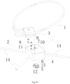
- a children rocking chair as shown in Fig. 1 is characterized by including a seat body 1, a supporting frame 2 and a seat body limiting mechanism 3, the supporting frame 2 includes a driving mechanism 4, the driving mechanism 4 includes a driving motor 5, a driving motor power output part 6 and a rotating shaft 7, the seat body 1 is used for carrying a child, there is only one rotating shaft 7 providing a sole support for the seat body 1, one end of the rotating shaft 7 pivots at the supporting frame 2 and is fixedly connected with the driving power output part 6, the other end of the rotating shaft 7 pivots at the seat body 1, and a vertical line from ground to a pivot point between the rotating shaft 7 and the supporting frame 2 deviates from a vertical line from the ground to a pivot point between the rotating shaft 7 and the seat body 1; the seat body limiting mechanism 3 includes a limiting piece 9 and a limiting matching piece 10 matched with the limiting piece 9, the limiting piece 9 is movably connected with the limiting matching piece 10, when the rotating shaft 7 rotates, the rotating shaft 7 is rotated relative to the
- the limiting piece 9 and the limiting matching piece 10 are movably connected in a relative distance moving mode, and when the rotating shaft 7 rotates, the limiting piece 9 and the limiting matching piece 10 move relatively at a certain distance so as to limit the included angle between the seat body 1 and the rotating shaft 7 to be kept at pre-set angles.
- the limiting piece 9 and the limiting matching piece 10 move at a certain distance, the limited angle is kept by the limiting piece 9 and the rotating shaft 7, the function is achieved more easily, and the structure is simpler.
- the limiting piece 9 is connected with the seat body 1, a vertical line from the ground to a connecting point between the limiting piece 9 and the seat body 1 deviates from a vertical line from the ground to a pivot point between the other end of the rotating shaft 7 and the seat body 1, and the limiting matching piece 10 is arranged on the supporting frame 2.
- the above is a preferred solution which has the advantage that when the rotating shaft 7 rotates, and the limiting piece 9 moves relative to the limiting matching piece 10 at a certain distance along with the seat body 1, the moving piece 9 on the seat body 1 always keeps a fixed distance with the pivot point of the rotating shaft 7 and the seat body 1 so as to prevent the seat body 1 from rotating around the rotating shaft 7, the connection between the limiting piece 9 and the seat body 1 deviates from a rotation axis to generate a force arm, and when the limiting piece 9 moves relative to the limiting matching piece 10 at a certain distance, it is more laborsaving to limit the angle set between the seat body 1 and the rotation shaft 7, so that the rotating shaft 7 swings more smoothly, and meanwhile, the force arm makes the seat body 1 more stable.
- the setting positions of the limiting piece 9 and the limiting matching piece 10 are different, as shown in the Fig. 12 , the limiting piece 9 is arranged on the mounting box 8, and the limiting matching piece 10 is movably connected with the seat body 1, therefore, either case belongs to the protection scope of the invention.
- the supporting frame 2 includes a base 14 and a mounting box 8, the mounting box 8 is connected with the base 14, the limiting piece 9 is a moving piece 9, the limiting matching piece 10 is a moving groove 10, when the rotating shaft 7 rotates, the moving piece 9 moves relative to the moving groove 10, the moving piece 9 is limited through the moving groove 10, the structure is simple, and implementation is easy.
- the moving piece 9 is arranged on the seat body 1, the moving groove 10 matched with the moving piece 9 is formed in the mounting box 8, the moving piece 9 is connected with the seat body 1, and the structure is simple by arranging the moving groove 10 in the mounting box 8.
- a rotating piece 11 is arranged on the moving piece 9, the rotating piece 11 can rotate around the moving piece 9, the rotating piece 11 is in surface fit with the moving groove 10, the rotating piece 11 is arranged on the moving groove 10 as to be in surface fit with the moving groove 10, the friction is reduced, the rocking chair for children swings smoothly, there are various kinds of rotating pieces 11, and the rotating piece 11 arranged on the moving piece 9 is a bearing.
- the moving groove 10 is an arc-shaped groove, when the rotating shaft 7 rotates from low to high and then to low, the arc-shaped groove is arranged from low to high and then to low, as shown in Fig. 1 , when the rotating shaft 7 is at the low position, the moving piece 9 of the moving groove 10 is also at the low position, as shown in Fig. 2 , when the rotating shaft 7 rotates to the high position, the moving piece 9 is also at the high position of the moving groove 10, as shown in Fig. 3 , when the rotating shaft 7 is at the low position, the moving piece 9 of the moving groove 10 is also at the low position, as shown in Fig. 1 , Fig. 2 and Fig.
- the moving groove 10 as shown in Fig. 1 , Fig. 2 and Fig. 3 is an arc-shaped groove.
- the moving groove 10 as shown in Fig. 9 and Fig. 10 is an arc-shaped groove, and a preferable solution as shown in Fig.
- the moving groove 10 has the advantage that the moving groove 10 becomes flatter and is close to a straight line, so that the rotating shaft 7 is smoother. From Fig. 7 to Fig. 10 , the seat body 1 not only swings back and forth in a distance moving mode relative to the supporting frame 2, but also swings left and right in an angle changing mode relative to the supporting frame 2, so that two different swing modes can be realized at the same time, the characteristics of low cost and good function are realized, and the moving groove 10 has various shapes, and any shape belongs to the protection range of the invention.
- the motion track line of the moving piece 9 moving from the starting point to the end point of the moving groove 10 is an arc, a vertical line connecting a highest point of the arc with a line connecting two end points of the arc is shorter than a vertical line connecting a highest point of another arc, formed by a rotating shaft 7 swinging from a starting point to an end point, with a line connecting two end points of the arc mentioned in latter, and the moving groove 10 is an arc-shaped groove.
- the moving groove 10 is an arc-shaped groove as shown in Fig. 9 and Fig. 10, and Fig.
- the moving groove 10 shows a preferred solution which has the advantages that the radian of the arc line of the moving groove 10 is reduced, so that the rotating shaft 7 is smoother, and Fig. 7 to Fig. 10 indicate that the seat body 1 swings back and forth in a distance moving mode relative to the supporting frame 2 and swings left and right in an angle changing mode relative to the supporting frame 2; therefore, two different swing modes can be achieved at the same time, the advantages of being low in achieving cost and good in function are achieved, the moving groove 10 has various shapes, and any shape belongs to the protection range of the invention.
- the motion track line of the moving piece 9 moving from a starting point to an end point of the moving groove 10 is an arc; a vertical line connecting a highest point of the arc with a line connecting two end points of the arc is equal to a vertical line connecting a highest point of another arc, formed by a rotating shaft swinging from a starting point to an end point, with a line connecting two end points of the arc mentioned in latter; and the moving groove 10 is an arc-shaped groove.
- the moving piece 9 of the moving groove 10 is also low when the rotating shaft 7 is at a low position, as shown in Fig.
- the moving piece 9 is also high in the moving groove 10 when the rotating shaft 7 is rotated to a high position, as shown in Fig. 3 , the moving piece 9 of the moving groove 10 is also low when the rotating shaft 7 is at a low position, Fig. 1 , Fig. 2 , and Fig. 3 refer to the motion process of the rotating shaft 7 from the starting point to the end point from the low position to the high position and then to the low position, and also refer to the motion process of the moving piece 9 from the low position to the high position and then to the low position.
- the moving groove 10 can be in various shapes such as a wave-shaped groove in the Fig. 12 and a U-shaped groove or a V-shaped groove, and the protection range of the device is not affected no matter which shape is.
- FIG. 14 Another implementation mode is shown in Fig. 14 , when the rotating shaft 7 swings from the starting point to the end point, a motion track line formed by the moving piece 9 moving from the starting point to the end point of the moving groove 10 is a straight line, and the moving groove 10 is a linear groove, this is another implementation mode, when the moving groove 10 is a linear groove, the angle generated by the seat body 1 relative to the supporting frame 2 is large.
- the matching point of the moving piece 9 and the moving groove 10 and the moving groove 10 are distributed on one side of the rotating shaft 7, so that the seat body 1 is prevented from rotating around the rotating shaft 7.
- a connecting line from a connecting point between the moving piece 9 and the seat body 1 to a pivot point between the seat body 1 and the rotating shaft 7 is perpendicular to a vertical line from the ground to the pivot point between the seat body 1 and the rotating shaft 7;
- a connecting line from the connecting point between the moving piece 9 and the seat body 1 to the pivot point between the seat body 1 and the rotating shaft 7 is perpendicular to a connecting line from a matching point between the moving piece 9 and the moving groove 10 to the connecting point between the moving piece 9 and the seat body 1; only in the state, the effect of limiting the seat body 1 to rotate around the rotating shaft 7 is the best.
- the moving groove is an inclined-plane groove
- the inclined-plane groove obliquely faces the rear direction of the seat body 1.
- the inclined-plane groove is obliquely arranged towards the rear direction of the seat body 1 so as to prevent the seat body 1 from inclining backwards after a child sits on the seat body 1, and after the seat body 1 inclines backwards, the limiting piece 9 is clamped with the rotating piece 11 on the limiting piece 9.
- the inclined-plane groove obliquely faces the rear direction of the seat body 1 so that the seat body 1 can move or swing smoothly.
- the moving groove 10 is roughly and symmetrically arranged on the two sides of the projection line, on the mounting box 8, of the rotating shaft 7 when the rotating shaft 7 rotates to the highest position, so that the layout of the moving groove 10 on the mounting box 8 is reasonable, and the size of the mounting box 8 is reduced.
- the moving groove 10 is arranged close to the pivot point of the rotating shaft 7 and the mounting box 8. Through the arrangement, the size of the mounting box 8 is reduced, and the appearance of the mounting box 8 is more attractive.
- the driving mechanism 4 further includes a sensor 12 arranged on the driving motor 5 and further includes a reduction gear set 13 connected to the driving motor 5, and the sensor 12 can control the driving motor 5 to continuously rotate forwards and backwards in a reciprocating mode, so that the rotating shaft 7 continuously rotates forwards and backwards in a reciprocating mode.
- the rotating angle of the rotating shaft 7 and positive and negative rotation of the driving motor 5 are detected through the sensor 12, the moving distance of the seat body 1 is controlled, speed reduction and force increasing are achieved through the reduction gear set 13, the structure is simple, and cost is low.
- the rotating shaft 7 is obliquely arranged on the mounting box 8, the cost can be reduced through the arrangement of the driving mechanism 4, the rotating shaft 7 is obliquely arranged on the mounting box 8 and is pivoted with the seat body 1, so that the seat body 1 generates conversion of kinetic energy and potential energy, and the aim of saving labor is achieved.
- two rotating pieces 11 are arranged on the moving piece 9, two moving grooves 10 correspondingly matched with the two rotating pieces 11 are formed in the mounting box 8, and the two rotating pieces 11 are arranged to prevent the moving piece 9 from rotating around the rotating shaft 7 along with the seat body 1 when the moving piece 9 moves relative to the moving grooves 10.
- the rocking chair for children has the advantages that the swing range is large, the cost is low, the seat body 1 is stable, the structure is simple, meanwhile, two different swing modes can be set, and the defects that the swing range is small, the process requirement is high, and only one swinging function can be achieved in the market are overcome.
- the rocking chair is simple in structure and low in cost, the seat body 1 is stable, two different swing modes can be realized at the same time, and the rocking chair is invented through long-term elaborate research of engineers, is not easily thought by those skilled in the field and is not common knowledge of the public.
- One end and the other end described in the invention are only used to describe the name of the thing, which can be understood as the top of the thing or a section of the thing.
Landscapes
- Chairs Characterized By Structure (AREA)
- Chairs For Special Purposes, Such As Reclining Chairs (AREA)
- Seats For Vehicles (AREA)
- Carriages For Children, Sleds, And Other Hand-Operated Vehicles (AREA)
Description
- The invention relates to a rocking chair for children.
- For families with infants and young children, in order to take care of children and have time to work or do housework, the parents have the urgent need to place their children on rocking chairs for children which are low in cost and large in swing range and can swing, especially place their children on rocking chairs for children which are low in cost and large in swing range and have various swing modes. A rocking chair with a seat and a rotating shaft fixed is available in the market, the seat rotates along with the rotating shaft, but children are easy to feel dizzy and uncomfortable. A rocking chair with two Z-shaped rotating shafts is available in the market, a seat body and the two rotating shafts are movably connected and the seat body swings in a distance relative to a supporting frame. However, the problems that the movement range is not large, the technological requirements of a seat body supporting seat, the shafts and a supporting frame are very high when the seat body rotates along with the two shafts, the cost is high, and only a single swing mode can be carried out due to the fact that the two shafts rotate exist. At present, a rocking chair for children which is large in swing range, low in cost and single in swing mode is needed in the market, and a rocking chair for children which is large in swing range and low in cost and can achieve two different swing modes at the same time is also needed.
CN201010124321 CN201020134178 US20100201171A1 discloses a child motion device, including a frame providing a structural support relative to a reference surface and including an armpivotably coupled to the structural support for reciprocatingmovement with a resonant frequency,a child supportingdevice coupled to the arm and spaced from the reference surface by the frame, and a drive system including a motorconfgured to drive the arm such that the child supportingdevice reciprocates along a motion path at a frequencymatched to the resonant frequency. - The invention aims to provide a rocking chair for children, which is large in swing range, low in cost and capable of realizing one swing mode, and also provide a rocking chair for children, which is large in swing range, low in cost, and capable of realizing two swing modes at the same time. The invention is identified in the appended set of claims.
- The invention is realized through the following technical solution:
A rocking chair for children includes a seat body, a supporting frame and a seat body limiting mechanism, the supporting frame includes a driving mechanism, the driving mechanism includes a driving motor, a driving motor power output part and a rotating shaft, the seat body is used for carrying a child, there is only one rotating shaft providing a sole support for the seat body, one end of the rotating shaft pivots at the supporting frame and is fixedly connected with the driving power output part, the other end of the rotating shaft pivots at the seat body, and a vertical line from ground to a pivot point between the rotating shaft and the supporting frame deviates from a vertical line from the ground to a pivot point between the rotating shaft and the seat body; the seat body limiting mechanism includes a limiting piece and a limiting matching piece matched with the limiting piece, the limiting piece is movably connected with the limiting matching piece, when the rotating shaft rotates, the rotating shaft is rotated relative to the seat body, and the seat body limiting mechanism limits the included angle between the seat body and the rotating shaft to be kept at pre-set angles. - As further optimization of the technology, the limiting piece and the limiting matching piece are movably connected in a relative distance moving mode, and when the rotating shaft rotates, the limiting piece and the limiting matching piece move relatively at a certain distance so as to limit the included angle between the seat body and the rotating shaft to be kept at pre-set angles.
- As further optimization of the technology, the limiting piece is connected with the seat body, and the limiting matching piece is arranged on the supporting frame; or the limiting piece is connected to the supporting frame and the limiting matching piece is arranged on the seat body.
- As further optimization of the technology, a vertical line from the ground to a connecting point between the limiting piece and the seat body deviates from a vertical line from the ground to a pivot point between the other end of the rotating shaft and the seat body.
- As further optimization of the technology, the supporting frame includes a base and a mounting box, the mounting box is connected with the base, the limiting piece is a moving piece, the limiting matching piece is a moving groove, when the rotating shaft rotates, the moving piece moves relative to the moving groove. The moving piece is arranged on the seat body, the moving groove matched with the moving piece is formed in the mounting box, and when the rotating shaft rotates, the limiting piece moves relative to the limiting matching piece at a certain distance along with the seat body.
- As further optimization of the technology, a rotating piece is arranged on the moving piece, the rotating piece is able to rotate around the moving piece, and the rotating piece is in surface fit with the moving groove.
- According to a preferred implementation mode, a motion track line of the moving piece moving from a starting point to an end point of the moving groove is an arc; a vertical line connecting a highest point of the arc with a line connecting two end points of the arc is shorter than a vertical line connecting a highest point of another arc, formed by a rotating shaft swinging from a starting point to an end point, with a line connecting two end points of the arc mentioned in latter, and the moving groove is an arc-shaped groove.
- As another implementation mode, a motion track line of the moving piece moving from a starting point to an end point of the moving groove is an arc; a vertical line connecting a highest point of the arc with a line connecting two end points of the arc is equal to a vertical line connecting a highest point of another arc, formed by a rotating shaft swinging from a starting point to an end point, with a line connecting two end points of the arc mentioned in latter, and the moving groove is an arc-shaped groove.
- As another implementation mode, when the rotating shaft swings from the starting point to the end point, the motion track line formed when the moving piece moves from the starting point to the end point of the moving groove is a straight line, and the moving groove is a linear groove.
- As further optimization of the technology, a matching point of the moving piece and the moving groove and the moving groove are distributed on one side of the rotating shaft.
- As further optimization of the technology, a connecting line from a connecting point between the moving piece and the seat body to a pivot point between the seat body and the rotating shaft is perpendicular to a vertical line from the ground to the pivot point between the seat body and the rotating shaft; the connecting line from the connecting point between the moving piece and the seat body to the pivot point between the seat body and the rotating shaft is perpendicular to a connecting line from a matching point between the moving piece and the moving groove to the connecting point between the moving piece and the seat body.
- As further optimization of the technology, when the seat body moves left and right, the moving groove is an inclined-plane groove, and the inclined-plane groove obliquely faces the rear direction of the seat body.
- As further optimization of the technology, the moving groove is an arc-shaped groove or an irregular wavy groove with alternating heights, and the moving groove is roughly and symmetrically formed in the two sides of a projection line, on the mounting box, of the rotating shaft when the rotating shaft rotates to the highest position.
- As further optimization of the technology, the moving groove is arranged close to a pivot point of the rotating shaft and the mounting box.
- As further optimization of the technology, the driving mechanism further includes a sensor arranged on the driving motor and a reduction gear set connected to the driving motor, and the sensor is able to control the driving motor to continuously rotate forwards and backwards in a reciprocating mode so that the rotating shaft is able to continuously rotate forwards and backwards in a reciprocating mode, and the rotating shaft is obliquely arranged on the mounting box.
- As further optimization of the technology, two rotating pieces are arranged on the moving piece, and two moving grooves correspondingly matched with the two rotating pieces are formed in the mounting box.
- Compared with the prior art, the invention has the following advantages:
The seat body is independently supported by one rotating shaft, the seat body and the rotating shaft rotate flexibly, and the defects that interference is caused when the seat body is pivoted through two shafts, the requirement for technology is high, and the swing range is small are overcome. According to the rocking chair for children, the limiting piece and the limiting matching piece move relatively at a certain distance to limit angles required by the seat body and the rotating shaft, so that different angles are set through the seat body and the rotating shaft when the rotating shaft rotates, one swing mode can be realized, and the rocking chair for children has the characteristics of large swing range, low cost, simple structure and stable seat body; the rocking chair for children can realize two different swing modes at the same time, and has the characteristics of large swing range, low cost, simple structure and stable seat body. - In order to more clearly explain the technical solution of the embodiment of the invention, the following will be briefly introduced in combination with the accompanying drawings. It is obvious that the accompanying drawings in the following description are only the specific embodiments of the invention, and for those skilled in the field, on the premise that creative labor is not paid, other drawings can be obtained according to the drawings.
-
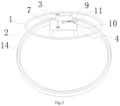
Fig. 1 is a structural schematic diagram of the rocking chair for children. -
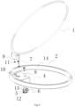
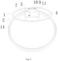
Fig. 2 is a structural schematic diagram of the rocking chair for children swinging from the starting point. -
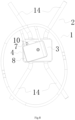
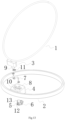
Fig. 3 is a structural schematic diagram of the rocking chair for children swinging to the midpoint. -
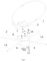
Fig. 4 is an explosion schematic diagram of the rocking chair for children. -
Fig. 5 is a sectional diagram of the moving groove of the rocking chair for children. -
Fig. 6 is a structural schematic diagram of the rocking chair for children that the moving groove is close to the pivot point of the rotating shaft and the mounting box. -
Fig. 7 is a structural schematic diagram that the seat body of the rocking chair for children swings to the left direction. -
Fig. 8 is a structure schematic diagram that the seat body of the rocking chair for children swings to the right direction. -
Fig. 9 is an explosion diagram ofFig. 8 . -
Fig. 10 is an explosion diagram ofFig. 7 . -
Fig. 11 is a structural schematic diagram of limited matching of the seat body of the rocking chair for children. -
Fig. 12 is an explosion schematic diagram of the irregular wave-shaped moving groove structure of the rocking chair for children. -
Fig. 13 is a structural schematic diagram that the rocking chair for children is provided with two rotating pieces. -
Fig. 14 is a structural schematic diagram of the linear groove of the rocking chair for children. - The embodiments of the invention are now described with reference to
Fig. 1-Fig. 14 . - A children rocking chair as shown in
Fig. 1 is characterized by including aseat body 1, a supportingframe 2 and a seatbody limiting mechanism 3, the supportingframe 2 includes adriving mechanism 4, thedriving mechanism 4 includes adriving motor 5, a driving motorpower output part 6 and arotating shaft 7, theseat body 1 is used for carrying a child, there is only onerotating shaft 7 providing a sole support for theseat body 1, one end of the rotatingshaft 7 pivots at the supportingframe 2 and is fixedly connected with the drivingpower output part 6, the other end of the rotatingshaft 7 pivots at theseat body 1, and a vertical line from ground to a pivot point between the rotatingshaft 7 and the supportingframe 2 deviates from a vertical line from the ground to a pivot point between the rotatingshaft 7 and theseat body 1; the seatbody limiting mechanism 3 includes alimiting piece 9 and a limiting matchingpiece 10 matched with thelimiting piece 9, thelimiting piece 9 is movably connected with the limiting matchingpiece 10, when the rotatingshaft 7 rotates, the rotatingshaft 7 is rotated relative to theseat body 1, and the seatbody limiting mechanism 3 limits the included angle between theseat body 1 and the rotatingshaft 7 to be kept at pre-set angles. - As shown in
Fig. 1 andFig. 11 , thelimiting piece 9 and the limiting matchingpiece 10 are movably connected in a relative distance moving mode, and when the rotatingshaft 7 rotates, thelimiting piece 9 and the limiting matchingpiece 10 move relatively at a certain distance so as to limit the included angle between theseat body 1 and the rotatingshaft 7 to be kept at pre-set angles. Thelimiting piece 9 and the limiting matchingpiece 10 move at a certain distance, the limited angle is kept by thelimiting piece 9 and therotating shaft 7, the function is achieved more easily, and the structure is simpler. - As shown in
Fig. 1 , thelimiting piece 9 is connected with theseat body 1, a vertical line from the ground to a connecting point between thelimiting piece 9 and theseat body 1 deviates from a vertical line from the ground to a pivot point between the other end of the rotatingshaft 7 and theseat body 1, and the limiting matchingpiece 10 is arranged on the supportingframe 2. The above is a preferred solution which has the advantage that when the rotatingshaft 7 rotates, and the limitingpiece 9 moves relative to the limiting matchingpiece 10 at a certain distance along with theseat body 1, themoving piece 9 on theseat body 1 always keeps a fixed distance with the pivot point of the rotatingshaft 7 and theseat body 1 so as to prevent theseat body 1 from rotating around the rotatingshaft 7, the connection between thelimiting piece 9 and theseat body 1 deviates from a rotation axis to generate a force arm, and when thelimiting piece 9 moves relative to the limiting matchingpiece 10 at a certain distance, it is more laborsaving to limit the angle set between theseat body 1 and therotation shaft 7, so that therotating shaft 7 swings more smoothly, and meanwhile, the force arm makes theseat body 1 more stable. The setting positions of thelimiting piece 9 and the limiting matchingpiece 10 are different, as shown in theFig. 12 , thelimiting piece 9 is arranged on themounting box 8, and the limiting matchingpiece 10 is movably connected with theseat body 1, therefore, either case belongs to the protection scope of the invention. - As shown in
Fig. 1 , the supportingframe 2 includes abase 14 and amounting box 8, themounting box 8 is connected with thebase 14, thelimiting piece 9 is a movingpiece 9, the limitingmatching piece 10 is a movinggroove 10, when therotating shaft 7 rotates, themoving piece 9 moves relative to the movinggroove 10, themoving piece 9 is limited through the movinggroove 10, the structure is simple, and implementation is easy. Themoving piece 9 is arranged on theseat body 1, the movinggroove 10 matched with themoving piece 9 is formed in themounting box 8, themoving piece 9 is connected with theseat body 1, and the structure is simple by arranging themoving groove 10 in themounting box 8. - As shown in
Fig. 4 , a rotatingpiece 11 is arranged on the movingpiece 9, the rotatingpiece 11 can rotate around the movingpiece 9, therotating piece 11 is in surface fit with the movinggroove 10, therotating piece 11 is arranged on the movinggroove 10 as to be in surface fit with the movinggroove 10, the friction is reduced, the rocking chair for children swings smoothly, there are various kinds of rotatingpieces 11, and therotating piece 11 arranged on themoving piece 9 is a bearing. - Preferably, the moving
groove 10 is an arc-shaped groove, when the rotatingshaft 7 rotates from low to high and then to low, the arc-shaped groove is arranged from low to high and then to low, as shown inFig. 1 , when therotating shaft 7 is at the low position, the movingpiece 9 of the movinggroove 10 is also at the low position, as shown inFig. 2 , when therotating shaft 7 rotates to the high position, the movingpiece 9 is also at the high position of the movinggroove 10, as shown inFig. 3 , when therotating shaft 7 is at the low position, themoving piece 9 of the movinggroove 10 is also at the low position, as shown inFig. 1 ,Fig. 2 andFig. 3 , the rotatingshaft 7 moves from the starting point to the end point from the low position to the high position and then to the low position, and the movingpiece 9 moves from the low position to the high position and then to the low position. The movinggroove 10 as shown inFig. 1 ,Fig. 2 andFig. 3 is an arc-shaped groove. When therotating shaft 7 rotates, theseat body 1 does not have angle change relative to the supportingframe 2 along with the swinging of therotating shaft 7 and only has distance movement swinging relative to the supportingframe 2, the movinggroove 10 as shown inFig. 9 andFig. 10 is an arc-shaped groove, and a preferable solution as shown inFig. 10 has the advantage that the movinggroove 10 becomes flatter and is close to a straight line, so that therotating shaft 7 is smoother. FromFig. 7 to Fig. 10 , theseat body 1 not only swings back and forth in a distance moving mode relative to the supportingframe 2, but also swings left and right in an angle changing mode relative to the supportingframe 2, so that two different swing modes can be realized at the same time, the characteristics of low cost and good function are realized, and the movinggroove 10 has various shapes, and any shape belongs to the protection range of the invention. - The motion track line of the moving
piece 9 moving from the starting point to the end point of the movinggroove 10 is an arc, a vertical line connecting a highest point of the arc with a line connecting two end points of the arc is shorter than a vertical line connecting a highest point of another arc, formed by arotating shaft 7 swinging from a starting point to an end point, with a line connecting two end points of the arc mentioned in latter, and the movinggroove 10 is an arc-shaped groove. As a preferred implementation mode, the movinggroove 10 is an arc-shaped groove as shown inFig. 9 andFig. 10, and Fig. 10 shows a preferred solution which has the advantages that the radian of the arc line of the movinggroove 10 is reduced, so that therotating shaft 7 is smoother, andFig. 7 to Fig. 10 indicate that theseat body 1 swings back and forth in a distance moving mode relative to the supportingframe 2 and swings left and right in an angle changing mode relative to the supportingframe 2; therefore, two different swing modes can be achieved at the same time, the advantages of being low in achieving cost and good in function are achieved, the movinggroove 10 has various shapes, and any shape belongs to the protection range of the invention. - The motion track line of the moving
piece 9 moving from a starting point to an end point of the movinggroove 10 is an arc; a vertical line connecting a highest point of the arc with a line connecting two end points of the arc is equal to a vertical line connecting a highest point of another arc, formed by a rotating shaft swinging from a starting point to an end point, with a line connecting two end points of the arc mentioned in latter; and the movinggroove 10 is an arc-shaped groove. In another implementation mode, as shown inFig. 1 , the movingpiece 9 of the movinggroove 10 is also low when therotating shaft 7 is at a low position, as shown inFig. 2 , the movingpiece 9 is also high in the movinggroove 10 when therotating shaft 7 is rotated to a high position, as shown inFig. 3 , the movingpiece 9 of the movinggroove 10 is also low when therotating shaft 7 is at a low position,Fig. 1 ,Fig. 2 , andFig. 3 refer to the motion process of therotating shaft 7 from the starting point to the end point from the low position to the high position and then to the low position, and also refer to the motion process of the movingpiece 9 from the low position to the high position and then to the low position. When therotating shaft 7 rotates, theseat body 1 does not have angle change relative to the supportingframe 2 along with the swinging of therotating shaft 7 and only has distance moving swinging relative to the supportingframe 2, the movinggroove 10 can be in various shapes such as a wave-shaped groove in theFig. 12 and a U-shaped groove or a V-shaped groove, and the protection range of the device is not affected no matter which shape is. - Another implementation mode is shown in
Fig. 14 , when therotating shaft 7 swings from the starting point to the end point, a motion track line formed by the movingpiece 9 moving from the starting point to the end point of the movinggroove 10 is a straight line, and the movinggroove 10 is a linear groove, this is another implementation mode, when the movinggroove 10 is a linear groove, the angle generated by theseat body 1 relative to the supportingframe 2 is large. - As shown in the
Fig. 1 , the matching point of the movingpiece 9 and the movinggroove 10 and the movinggroove 10 are distributed on one side of therotating shaft 7, so that theseat body 1 is prevented from rotating around therotating shaft 7. - As shown in
Fig. 1 , a connecting line from a connecting point between the movingpiece 9 and theseat body 1 to a pivot point between theseat body 1 and therotating shaft 7 is perpendicular to a vertical line from the ground to the pivot point between theseat body 1 and therotating shaft 7; a connecting line from the connecting point between the movingpiece 9 and theseat body 1 to the pivot point between theseat body 1 and therotating shaft 7 is perpendicular to a connecting line from a matching point between the movingpiece 9 and the movinggroove 10 to the connecting point between the movingpiece 9 and theseat body 1; only in the state, the effect of limiting theseat body 1 to rotate around therotating shaft 7 is the best. - As shown in
Fig. 5 , when theseat body 1 moves left and right, the moving groove is an inclined-plane groove, and the inclined-plane groove obliquely faces the rear direction of theseat body 1. The inclined-plane groove is obliquely arranged towards the rear direction of theseat body 1 so as to prevent theseat body 1 from inclining backwards after a child sits on theseat body 1, and after theseat body 1 inclines backwards, the limitingpiece 9 is clamped with the rotatingpiece 11 on the limitingpiece 9. The inclined-plane groove obliquely faces the rear direction of theseat body 1 so that theseat body 1 can move or swing smoothly. - As shown in the
Fig. 6 , the movinggroove 10 is roughly and symmetrically arranged on the two sides of the projection line, on the mountingbox 8, of therotating shaft 7 when therotating shaft 7 rotates to the highest position, so that the layout of the movinggroove 10 on the mountingbox 8 is reasonable, and the size of the mountingbox 8 is reduced. - The moving
groove 10 is arranged close to the pivot point of therotating shaft 7 and the mountingbox 8. Through the arrangement, the size of the mountingbox 8 is reduced, and the appearance of the mountingbox 8 is more attractive. - The
driving mechanism 4 further includes asensor 12 arranged on the drivingmotor 5 and further includes a reduction gear set 13 connected to the drivingmotor 5, and thesensor 12 can control the drivingmotor 5 to continuously rotate forwards and backwards in a reciprocating mode, so that therotating shaft 7 continuously rotates forwards and backwards in a reciprocating mode. The rotating angle of therotating shaft 7 and positive and negative rotation of the drivingmotor 5 are detected through thesensor 12, the moving distance of theseat body 1 is controlled, speed reduction and force increasing are achieved through the reduction gear set 13, the structure is simple, and cost is low. Therotating shaft 7 is obliquely arranged on the mountingbox 8, the cost can be reduced through the arrangement of thedriving mechanism 4, therotating shaft 7 is obliquely arranged on the mountingbox 8 and is pivoted with theseat body 1, so that theseat body 1 generates conversion of kinetic energy and potential energy, and the aim of saving labor is achieved. - As shown in the
Fig. 13 , two rotatingpieces 11 are arranged on the movingpiece 9, two movinggrooves 10 correspondingly matched with the tworotating pieces 11 are formed in themounting box 8, and the tworotating pieces 11 are arranged to prevent the movingpiece 9 from rotating around therotating shaft 7 along with theseat body 1 when the movingpiece 9 moves relative to the movinggrooves 10. - The rocking chair for children has the advantages that the swing range is large, the cost is low, the
seat body 1 is stable, the structure is simple, meanwhile, two different swing modes can be set, and the defects that the swing range is small, the process requirement is high, and only one swinging function can be achieved in the market are overcome. The rocking chair is simple in structure and low in cost, theseat body 1 is stable, two different swing modes can be realized at the same time, and the rocking chair is invented through long-term elaborate research of engineers, is not easily thought by those skilled in the field and is not common knowledge of the public. One end and the other end described in the invention are only used to describe the name of the thing, which can be understood as the top of the thing or a section of the thing. - Although the invention has been described above with reference to embodiments, various improvements can be made without departing from the scope of the invention, and the invention can be implemented in other ways equivalent or well-known to those skilled in the art. In particular, as long as there is no structural conflict, the features in the embodiments disclosed in the invention can be combined with each other in any way. The description does not describe these combinations exhaustively, just for the sake of omitting space and saving resources. Therefore, the invention is not limited to the specific embodiments disclosed herein, but includes all technical solutions falling within the scope of the claims.
Claims (15)
- A rocking chair for children, characterized by comprising a seat body (1), a supporting frame (2) and a seat body limiting mechanism (3), wherein the supporting frame (2) comprises a driving mechanism (4), the driving mechanism (4) comprises a driving motor (5), a driving motor power output part (6) and a rotating shaft (7), the seat body (1) is used for carrying a child, there is only one rotating shaft (7) providing a sole support for the seat body (1), one end of the rotating shaft (7) pivots at the supporting frame (2) and is fixedly connected with the driving motor power output part (6), another end of the rotating shaft (7) pivots at the seat body (1), and a vertical line from ground to a pivot point between the rotating shaft (7) and the supporting frame (2) deviates from a vertical line from the ground to a pivot point between the rotating shaft (7) and the seat body (1); the seat body limiting mechanism (3) comprises a limiting piece (9) and a limiting matching piece (10) matched with the limiting piece (9), the limiting piece (9) is movably connected with the limiting matching piece (10), when the rotating shaft (7) rotates, the rotating shaft (7) is rotated relative to the seat body (1), and the seat body limiting mechanism (3) limits an included angle between the seat body (1) and the rotating shaft (7) to be kept at pre-set angles; wherein the limiting piece (9) is connected with the seat body (1), and the limiting matching piece (10) is arranged on the supporting frame (2); or the limiting piece (9) is connected to the supporting frame (2), and the limiting matching piece (10) is arranged on the seat body (1).
- The rocking chair for children according to claim 1, characterized in that the limiting piece (9) and the limiting matching piece (10) are movably connected in a relative distance moving mode, and when the rotating shaft (7) rotates, the limiting piece (9) and the limiting matching piece (10) move relatively at a certain distance so as to limit the included angle between the seat body (1) and the rotating shaft (7) to be kept at pre-set angles.
- The rocking chair for children according to claim 1, characterized in that a vertical line from the ground to a connecting point between the limiting piece (9) and the seat body (1) deviates from a vertical line from ground to a pivot point between another end of the rotating shaft (7) and the seat body (1).
- The rocking chair for children according to claim 3, characterized in that the supporting frame (2) comprises a base (14) and a mounting box (8), the mounting box (8) is connected with the base (14), the limiting piece (9) is a moving piece (9), the limiting matching piece (10) is a moving groove (10), when the rotating shaft (7) rotates, the moving piece (9) moves relative to the moving groove (10), the moving piece (9) is arranged on the seat body (1), the moving groove (10) matched with the moving piece (9) is formed in the mounting box (8), and when the rotating shaft (7) rotates, the limiting piece (9) moves relative to the limiting matching piece (10) at a certain distance along with the seat body (1).
- The rocking chair for children according to claim 4, characterized in that a rotating piece (11) is arranged on the moving piece (9), the rotating piece (11) is able to rotate around the moving piece (9), and the rotating piece (11) is in surface fit with the moving groove (10).
- The rocking chair for children according to claim 5, characterized in that a motion track line of the moving piece (9) moving from a starting point to an end point of the moving groove (10) is an arc; a vertical line connecting a highest point of the arc with a line connecting two end points of the arc is shorter than a vertical line connecting a highest point of another arc, formed by the rotating shaft (7) rotating from a starting point to an end point, with a line connecting two end points of the arc mentioned in latter; and the moving groove (10) is an arc-shaped groove.
- The rocking chair for children according to claim 5, characterized in that a motion track line of the moving piece (9) moving from a starting point to an end point of the moving groove (10) is an arc; a vertical line connecting a highest point of the arc with a line connecting two end points of the arc is equal to a vertical line connecting a highest point of another arc, formed by the rotating shaft (7) rotating from a starting point to an end point, with a line connecting two end points of the arc mentioned in latter; and the moving groove (10) is an arc-shaped groove.
- The rocking chair for children according to claim 5, characterized in that when the rotating shaft (7) swings from a starting point to the end point, a motion track line formed when the moving piece (9) moves from the starting point to an end point of the moving groove (10) is a straight line, and the moving groove (10) is a linear groove.
- The rocking chair for children according to claim 5, characterized in that a matching point of the moving piece (9) and the moving groove (10) and the moving groove (10) are distributed on one side of the rotating shaft.
- The rocking chair for children according to claim 9, characterized in that a connecting line from a connecting point between the moving piece (9) and the seat body (1) to a pivot point between the seat body (1) and the rotating shaft (7) is perpendicular to a vertical line from the ground to the pivot point between the seat body (1) and the rotating shaft (7); the connecting line from the connecting point between the moving piece (9) and the seat body (1) to the pivot point between the seat body (1) and the rotating shaft (7) is perpendicular to a connecting line from a matching point between the moving piece (9) and the moving groove (10) to the connecting point between the moving piece (9) and the seat body (1).
- The rocking chair for children according to claim 7, characterized in that the moving groove (10) is an inclined-plane groove, and the inclined-plane groove obliquely faces a rear direction of the seat body (1).
- The rocking chair for children according to claim 5, characterized in that the moving groove (10) is an arc-shaped groove or an irregular wavy groove with alternating heights, and the moving groove (10) is roughly and symmetrically formed in two sides of a projection line, on the mounting box (8), of the rotating shaft (7) when the rotating shaft (7) rotates to a highest position.
- The rocking chair for children according to claim 12, characterized in that the moving groove (10) is arranged close to a pivot point of the rotating shaft (7) and the mounting box (8).
- The rocking chair for children according to claim 1, characterized in that the driving mechanism (4) further comprises a sensor (12) arranged on the driving motor (5) and a reduction gear set (13) connected to the driving motor (5), and the sensor (12) is able to control the driving motor (5) to continuously rotate forwards and backwards in a reciprocating mode so that the rotating shaft (7) is able to continuously rotate forwards and backwards in a reciprocating mode, and the rotating shaft (7) is obliquely arranged on a mounting box (8).
- The rocking chair for children according to claim 13, characterized in that two rotating pieces (11) are arranged on the moving piece (9), and two moving grooves (10) correspondingly matched with the two rotating pieces (11) are formed in the mounting box (8).
Applications Claiming Priority (3)
| Application Number | Priority Date | Filing Date | Title |
|---|---|---|---|
| CN202010056648 | 2020-01-18 | ||
| CN202010197938.2A CN111134487B (en) | 2020-01-18 | 2020-03-19 | Rocking chair for children |
| PCT/CN2021/080922 WO2021185226A1 (en) | 2020-01-18 | 2021-03-16 | Rocking chair for children |
Publications (4)
| Publication Number | Publication Date |
|---|---|
| EP4082401A1 EP4082401A1 (en) | 2022-11-02 |
| EP4082401A4 EP4082401A4 (en) | 2023-06-28 |
| EP4082401B1 true EP4082401B1 (en) | 2025-06-11 |
| EP4082401C0 EP4082401C0 (en) | 2025-06-11 |
Family
ID=70528710
Family Applications (1)
| Application Number | Title | Priority Date | Filing Date |
|---|---|---|---|
| EP21772365.9A Active EP4082401B1 (en) | 2020-01-18 | 2021-03-16 | Rocking chair for children |
Country Status (5)
| Country | Link |
|---|---|
| US (3) | US12144437B2 (en) |
| EP (1) | EP4082401B1 (en) |
| CN (13) | CN113133612B (en) |
| PL (1) | PL4082401T3 (en) |
| WO (3) | WO2022041481A1 (en) |
Families Citing this family (5)
| Publication number | Priority date | Publication date | Assignee | Title |
|---|---|---|---|---|
| CN113133612B (en) * | 2020-01-18 | 2026-01-27 | 中山市童印儿童用品有限公司 | Rocking chair for children |
| CN112294032B (en) * | 2020-06-20 | 2025-11-14 | 中山市童印儿童用品有限公司 | A rocking chair |
| CN114747904A (en) * | 2021-01-11 | 2022-07-15 | 中山市童印儿童用品有限公司 | Rocking chair for children |
| CN112971452B (en) * | 2021-04-07 | 2023-04-28 | 欧的珠 | Rocking mechanism and crib with same |
| CN116849488A (en) * | 2023-08-03 | 2023-10-10 | 广东优呗母婴科技有限公司 | Cradle movement device and cradle |
Family Cites Families (58)
| Publication number | Priority date | Publication date | Assignee | Title |
|---|---|---|---|---|
| US5988670A (en) * | 1995-02-15 | 1999-11-23 | Jiangsu Goodbaby Group, Inc. | Child carrier |
| KR200235182Y1 (en) * | 1997-12-31 | 2001-10-25 | 김도형 | Driving device for infant crib |
| CN2356589Y (en) * | 1998-09-11 | 2000-01-05 | 马维儒 | Electric cradle |
| CN2441708Y (en) * | 2000-04-07 | 2001-08-08 | 陈磊 | Multifunction children cart |
| US6471597B1 (en) * | 2000-10-27 | 2002-10-29 | Regalo International, Llc | Open top swing |
| US6574806B1 (en) * | 2001-12-28 | 2003-06-10 | Charles E. Maher | Infant seat rocking device |
| US20050264063A1 (en) * | 2004-05-12 | 2005-12-01 | Diane Babcock | Rocking infant carrier |
| WO2006010972A1 (en) * | 2004-06-28 | 2006-02-02 | Jetta Company Limited | Baby bouncer actuator |
| US8187111B2 (en) * | 2005-11-03 | 2012-05-29 | Graco Children's Products Inc. | Child motion device |
| US7686390B2 (en) * | 2007-11-07 | 2010-03-30 | Montecito Research | Motion simulation chair |
| US7669927B1 (en) * | 2009-04-23 | 2010-03-02 | Zaid Zakiya M | Infant car seat |
| CN101756561B (en) * | 2010-01-11 | 2011-08-31 | 好孩子儿童用品有限公司 | Baby rocking chair |
| CN201767558U (en) * | 2010-01-19 | 2011-03-23 | 好孩子儿童用品有限公司 | Infant rocking chair |
| CN201729241U (en) * | 2010-01-27 | 2011-02-02 | 平湖市双喜童车制造有限公司 | Device for limiting and locking direction of front wheel of children motor-driven toy car |
| CN201624403U (en) * | 2010-02-21 | 2010-11-10 | 好孩子儿童用品有限公司 | baby rocking chair |
| CN101773344B (en) * | 2010-02-21 | 2012-01-04 | 好孩子儿童用品有限公司 | Children rocking chair |
| CN202035820U (en) * | 2010-11-15 | 2011-11-16 | 好孩子儿童用品有限公司 | Children rocking chair |
| CN202077958U (en) * | 2011-02-15 | 2011-12-21 | 好孩子儿童用品有限公司 | Rocking chair for babies |
| CN102894731A (en) * | 2011-07-28 | 2013-01-30 | 儿童二代公司 | Children's motion device |
| CN103300636B (en) * | 2012-03-05 | 2015-10-28 | 明门香港股份有限公司 | Baby swinging device |
| CN103355994B (en) * | 2012-03-28 | 2016-12-28 | 宝钜儿童用品香港股份有限公司 | Child seat apparatus |
| CN202681302U (en) * | 2012-04-28 | 2013-01-23 | 好孩子儿童用品有限公司 | children's rocking chair |
| CN203028724U (en) * | 2013-01-05 | 2013-07-03 | 好孩子儿童用品有限公司 | Electric rocking chair |
| EP2967232A4 (en) * | 2013-03-15 | 2016-08-31 | Thorley Ind Llc | Driven infant seat |
| AU2014201661B2 (en) * | 2013-03-21 | 2016-01-14 | Wonderland Nurserygoods Company Limited | Infant swing apparatus |
| CN103445571B (en) * | 2013-09-26 | 2016-09-07 | 中山市乐瑞婴童用品有限公司 | The carrier skeleton of modes |
| CN203693088U (en) * | 2014-01-06 | 2014-07-09 | 东莞市智乐堡儿童玩具有限公司 | Children's rocking chair and rocking comfort device |
| CN104825009B (en) * | 2014-01-16 | 2017-09-22 | 明门香港股份有限公司 | Children's seat |
| CN104840041B (en) * | 2014-02-17 | 2018-08-10 | 明门香港股份有限公司 | Infant carrier |
| US9295342B2 (en) * | 2014-03-20 | 2016-03-29 | Dorel Juvenile Group, Inc. | Height adjustor for infant swing unit |
| US9861210B2 (en) * | 2015-09-09 | 2018-01-09 | Kids Ii, Inc. | Dual arm child motion device |
| US20160058201A1 (en) * | 2014-08-29 | 2016-03-03 | Thorley Industries, Llc | Infant-supporting devices |
| CN204105348U (en) * | 2014-09-29 | 2015-01-21 | 好孩子儿童用品有限公司 | Electric rocking chair |
| CN105725594B (en) * | 2014-12-30 | 2018-12-11 | 明门香港股份有限公司 | Children's mobile device with foldable frame |
| CN205885159U (en) * | 2016-01-07 | 2017-01-18 | 王俊茹 | Automatic baby's rocking chair sways |
| US20170251828A1 (en) * | 2016-03-07 | 2017-09-07 | Kids Ii, Inc. | Folding elevated sleeper |
| US9968204B2 (en) * | 2016-04-04 | 2018-05-15 | Wonderland Switzerland Ag | Child motion apparatus |
| US10327566B2 (en) * | 2016-06-27 | 2019-06-25 | Wonderland Switzerland Ag | Infant carrier and swing device therewith |
| CN206119795U (en) * | 2016-08-15 | 2017-04-26 | 宁波希禾儿童用品有限公司 | Rocking chair |
| CN206964445U (en) * | 2017-02-21 | 2018-02-06 | 昆山乐奇儿童用品有限公司 | A kind of baby rocking chair drive mechanism |
| GB2560984B (en) * | 2017-03-31 | 2022-06-15 | N2M Ltd | A rocking device |
| US10470585B2 (en) * | 2017-04-12 | 2019-11-12 | Graco Children's Products Inc. | Apparatus and method for an adjustable mode child rocker and swing |
| US10702073B2 (en) * | 2017-05-12 | 2020-07-07 | Steven Paperno | Portable rocker for newborn baby or infant |
| CN107232830B (en) * | 2017-07-28 | 2020-12-11 | 浙江永强集团股份有限公司 | Solar garden rocking chair |
| US20190298064A1 (en) * | 2018-03-30 | 2019-10-03 | Lung-Tan Shih | Base seat for bed or chair |
| US10376061B1 (en) * | 2018-04-12 | 2019-08-13 | Hhc Changzhou Corporation | Swivel base assembly for use in conjunction with an electrically powered chair |
| CN109450308B (en) * | 2018-10-30 | 2020-11-03 | 昆山乐奇儿童用品有限公司 | Swing drive control device and method |
| CN109393837B (en) * | 2018-11-30 | 2024-03-15 | 宁波霍科电器有限公司 | A rockable Z-shaped children's dining chair |
| CN209574060U (en) * | 2018-11-30 | 2019-11-05 | 宁波霍科电器有限公司 | A rockable Z-shaped children's dining chair |
| CN111297118B (en) * | 2018-12-12 | 2025-02-07 | 中山市童印儿童用品有限公司 | A lifting chair |
| CN209360180U (en) * | 2018-12-12 | 2019-09-10 | 昆山乐奇儿童用品有限公司 | A kind of electric swing that front and rear, left and right is waved |
| CN210169534U (en) * | 2019-04-22 | 2020-03-24 | 佛山市熊宝宝科技有限公司 | Foldable bracket of rocking chair |
| CN110037467B (en) * | 2019-04-22 | 2024-12-10 | 佛山市熊宝宝科技有限公司 | Folding electric rocking chair |
| US11944212B2 (en) * | 2019-09-19 | 2024-04-02 | Thorley Industries, Llc | Infant care apparatus |
| CN110720775A (en) * | 2019-10-15 | 2020-01-24 | 永艺家具股份有限公司 | Inclination and elevation locking control device of dynamic tray |
| CN113133612B (en) * | 2020-01-18 | 2026-01-27 | 中山市童印儿童用品有限公司 | Rocking chair for children |
| CN111166107B (en) * | 2020-03-09 | 2022-06-17 | 中山市波比儿童用品有限公司 | Infant care apparatus and drive mechanism |
| TWI853679B (en) * | 2020-03-27 | 2024-08-21 | 瑞士商明門瑞士股份有限公司 | Swing apparatus with magnetic drive and control |
-
2020
- 2020-03-17 CN CN202010188432.5A patent/CN113133612B/en active Active
- 2020-03-19 CN CN202010198426.8A patent/CN113133613A/en active Pending
- 2020-03-19 CN CN202010197938.2A patent/CN111134487B/en active Active
- 2020-03-19 CN CN202020354252.5U patent/CN212755003U/en not_active Withdrawn - After Issue
- 2020-05-18 CN CN202020830628.5U patent/CN215993432U/en not_active Withdrawn - After Issue
- 2020-05-18 CN CN202010421405.8A patent/CN112089265B/en active Active
- 2020-07-29 CN CN202010746519.XA patent/CN113133614B/en active Active
- 2020-08-27 CN CN202010880515.0A patent/CN112021870A/en active Pending
- 2020-08-27 CN CN202021826688.6U patent/CN212755006U/en active Active
- 2020-11-04 CN CN202022522059.0U patent/CN215271711U/en not_active Expired - Fee Related
- 2020-11-04 CN CN202011218732.XA patent/CN112450651B/en active Active
- 2020-11-06 WO PCT/CN2020/126928 patent/WO2022041481A1/en not_active Ceased
- 2020-11-06 WO PCT/CN2020/126950 patent/WO2021232695A1/en not_active Ceased
-
2021
- 2021-01-16 CN CN202120115461.9U patent/CN215604525U/en not_active Withdrawn - After Issue
- 2021-01-16 CN CN202110058796.6A patent/CN113133615B/en active Active
- 2021-03-16 WO PCT/CN2021/080922 patent/WO2021185226A1/en not_active Ceased
- 2021-03-16 PL PL21772365.9T patent/PL4082401T3/en unknown
- 2021-03-16 EP EP21772365.9A patent/EP4082401B1/en active Active
-
2022
- 2022-04-07 US US17/715,948 patent/US12144437B2/en active Active
- 2022-04-13 US US17/719,396 patent/US11957253B2/en active Active
-
2023
- 2023-02-23 US US18/113,619 patent/US12357110B2/en active Active
Also Published As
| Publication number | Publication date |
|---|---|
| CN113133614B (en) | 2026-01-27 |
| CN113133612B (en) | 2026-01-27 |
| PL4082401T3 (en) | 2025-11-12 |
| EP4082401C0 (en) | 2025-06-11 |
| CN215271711U (en) | 2021-12-24 |
| CN111134487A (en) | 2020-05-12 |
| US20220232997A1 (en) | 2022-07-28 |
| WO2021185226A1 (en) | 2021-09-23 |
| CN113133612A (en) | 2021-07-20 |
| CN113133615B (en) | 2026-01-27 |
| US12357110B2 (en) | 2025-07-15 |
| EP4082401A1 (en) | 2022-11-02 |
| US12144437B2 (en) | 2024-11-19 |
| CN113133615A (en) | 2021-07-20 |
| EP4082401A4 (en) | 2023-06-28 |
| CN112089265B (en) | 2026-01-23 |
| CN111134487B (en) | 2026-01-27 |
| US20220225789A1 (en) | 2022-07-21 |
| US11957253B2 (en) | 2024-04-16 |
| WO2022041481A1 (en) | 2022-03-03 |
| CN215993432U (en) | 2022-03-11 |
| WO2021232695A1 (en) | 2021-11-25 |
| CN212755003U (en) | 2021-03-23 |
| CN112021870A (en) | 2020-12-04 |
| CN215604525U (en) | 2022-01-25 |
| CN112450651B (en) | 2026-01-23 |
| CN113133613A (en) | 2021-07-20 |
| US20230190011A1 (en) | 2023-06-22 |
| CN212755006U (en) | 2021-03-23 |
| CN112089265A (en) | 2020-12-18 |
| CN112450651A (en) | 2021-03-09 |
| CN113133614A (en) | 2021-07-20 |
Similar Documents
| Publication | Publication Date | Title |
|---|---|---|
| US11957253B2 (en) | Rocking chair for children | |
| US4722521A (en) | Mechanism for maintaining a swinging movement | |
| CN103315566A (en) | baby swing | |
| US20230124305A1 (en) | Device for taking care of infants, and driving mechanism | |
| CN219578615U (en) | rocking chair for children | |
| TWI546977B (en) | Tilt type sun tracking device | |
| RU2799290C1 (en) | Rocking chair for children | |
| JP2018140700A (en) | Driving wheel unit and automatic carrying truck | |
| CN110626413A (en) | Swing drive device and swing car | |
| CN223220221U (en) | Swing structure and baby rocking chair comprising same | |
| CN221153627U (en) | Novel crib | |
| CN220655197U (en) | Sofa capable of rotating hair nourishing and washing | |
| CN217243486U (en) | Swing device and baby crib | |
| CN222997654U (en) | A children's rocking device | |
| CN221997447U (en) | Movement assembly of a rocking chair | |
| CN223013183U (en) | Parallel type movement mechanism | |
| CN211786767U (en) | Multifunctional obstacle avoidance trolley | |
| CN114747904A (en) | Rocking chair for children | |
| CN210854045U (en) | Power transmission mechanism | |
| TWM646026U (en) | Coaxial twin-rotor aircraft | |
| CN111270880A (en) | Turntable mechanism | |
| JPH0526319A (en) | Oscillation mechanism and reflecting mirror driving gear using it | |
| CN106026509A (en) | Wabbler mechanism capable of maintaining self-balance | |
| JPS59134397A (en) | Swivel ceiling fan |
Legal Events
| Date | Code | Title | Description |
|---|---|---|---|
| STAA | Information on the status of an ep patent application or granted ep patent |
Free format text: STATUS: THE INTERNATIONAL PUBLICATION HAS BEEN MADE |
|
| PUAI | Public reference made under article 153(3) epc to a published international application that has entered the european phase |
Free format text: ORIGINAL CODE: 0009012 |
|
| STAA | Information on the status of an ep patent application or granted ep patent |
Free format text: STATUS: REQUEST FOR EXAMINATION WAS MADE |
|
| 17P | Request for examination filed |
Effective date: 20220729 |
|
| AK | Designated contracting states |
Kind code of ref document: A1 Designated state(s): AL AT BE BG CH CY CZ DE DK EE ES FI FR GB GR HR HU IE IS IT LI LT LU LV MC MK MT NL NO PL PT RO RS SE SI SK SM TR |
|
| A4 | Supplementary search report drawn up and despatched |
Effective date: 20230531 |
|
| DAV | Request for validation of the european patent (deleted) | ||
| DAX | Request for extension of the european patent (deleted) | ||
| RIC1 | Information provided on ipc code assigned before grant |
Ipc: A47D 13/10 20060101AFI20230524BHEP |
|
| STAA | Information on the status of an ep patent application or granted ep patent |
Free format text: STATUS: EXAMINATION IS IN PROGRESS |
|
| 17Q | First examination report despatched |
Effective date: 20240313 |
|
| GRAP | Despatch of communication of intention to grant a patent |
Free format text: ORIGINAL CODE: EPIDOSNIGR1 |
|
| STAA | Information on the status of an ep patent application or granted ep patent |
Free format text: STATUS: GRANT OF PATENT IS INTENDED |
|
| INTG | Intention to grant announced |
Effective date: 20250217 |
|
| GRAS | Grant fee paid |
Free format text: ORIGINAL CODE: EPIDOSNIGR3 |
|
| GRAA | (expected) grant |
Free format text: ORIGINAL CODE: 0009210 |
|
| STAA | Information on the status of an ep patent application or granted ep patent |
Free format text: STATUS: THE PATENT HAS BEEN GRANTED |
|
| AK | Designated contracting states |
Kind code of ref document: B1 Designated state(s): AL AT BE BG CH CY CZ DE DK EE ES FI FR GB GR HR HU IE IS IT LI LT LU LV MC MK MT NL NO PL PT RO RS SE SI SK SM TR |
|
| REG | Reference to a national code |
Ref country code: GB Ref legal event code: FG4D |
|
| REG | Reference to a national code |
Ref country code: CH Ref legal event code: EP |
|
| REG | Reference to a national code |
Ref country code: IE Ref legal event code: FG4D |
|
| REG | Reference to a national code |
Ref country code: DE Ref legal event code: R096 Ref document number: 602021032174 Country of ref document: DE |
|
| U01 | Request for unitary effect filed |
Effective date: 20250626 |
|
| U07 | Unitary effect registered |
Designated state(s): AT BE BG DE DK EE FI FR IT LT LU LV MT NL PT RO SE SI Effective date: 20250702 |
|
| PG25 | Lapsed in a contracting state [announced via postgrant information from national office to epo] |
Ref country code: ES Free format text: LAPSE BECAUSE OF FAILURE TO SUBMIT A TRANSLATION OF THE DESCRIPTION OR TO PAY THE FEE WITHIN THE PRESCRIBED TIME-LIMIT Effective date: 20250611 |
|
| PG25 | Lapsed in a contracting state [announced via postgrant information from national office to epo] |
Ref country code: NO Free format text: LAPSE BECAUSE OF FAILURE TO SUBMIT A TRANSLATION OF THE DESCRIPTION OR TO PAY THE FEE WITHIN THE PRESCRIBED TIME-LIMIT Effective date: 20250911 Ref country code: GR Free format text: LAPSE BECAUSE OF FAILURE TO SUBMIT A TRANSLATION OF THE DESCRIPTION OR TO PAY THE FEE WITHIN THE PRESCRIBED TIME-LIMIT Effective date: 20250912 |
|
| PG25 | Lapsed in a contracting state [announced via postgrant information from national office to epo] |
Ref country code: HR Free format text: LAPSE BECAUSE OF FAILURE TO SUBMIT A TRANSLATION OF THE DESCRIPTION OR TO PAY THE FEE WITHIN THE PRESCRIBED TIME-LIMIT Effective date: 20250611 |
|
| PG25 | Lapsed in a contracting state [announced via postgrant information from national office to epo] |
Ref country code: RS Free format text: LAPSE BECAUSE OF FAILURE TO SUBMIT A TRANSLATION OF THE DESCRIPTION OR TO PAY THE FEE WITHIN THE PRESCRIBED TIME-LIMIT Effective date: 20250911 |
|
| U1N | Appointed representative for the unitary patent procedure changed after the registration of the unitary effect |
Representative=s name: SANTARELLI; FR |
|
| PG25 | Lapsed in a contracting state [announced via postgrant information from national office to epo] |
Ref country code: IS Free format text: LAPSE BECAUSE OF FAILURE TO SUBMIT A TRANSLATION OF THE DESCRIPTION OR TO PAY THE FEE WITHIN THE PRESCRIBED TIME-LIMIT Effective date: 20251011 |
|
| PG25 | Lapsed in a contracting state [announced via postgrant information from national office to epo] |
Ref country code: SM Free format text: LAPSE BECAUSE OF FAILURE TO SUBMIT A TRANSLATION OF THE DESCRIPTION OR TO PAY THE FEE WITHIN THE PRESCRIBED TIME-LIMIT Effective date: 20250611 |
|
| PG25 | Lapsed in a contracting state [announced via postgrant information from national office to epo] |
Ref country code: CZ Free format text: LAPSE BECAUSE OF FAILURE TO SUBMIT A TRANSLATION OF THE DESCRIPTION OR TO PAY THE FEE WITHIN THE PRESCRIBED TIME-LIMIT Effective date: 20250611 |
|
| PG25 | Lapsed in a contracting state [announced via postgrant information from national office to epo] |
Ref country code: SK Free format text: LAPSE BECAUSE OF FAILURE TO SUBMIT A TRANSLATION OF THE DESCRIPTION OR TO PAY THE FEE WITHIN THE PRESCRIBED TIME-LIMIT Effective date: 20250611 |
|
| PGFP | Annual fee paid to national office [announced via postgrant information from national office to epo] |
Ref country code: GB Payment date: 20260330 Year of fee payment: 6 |
|
| PLBE | No opposition filed within time limit |
Free format text: ORIGINAL CODE: 0009261 |
|
| STAA | Information on the status of an ep patent application or granted ep patent |
Free format text: STATUS: NO OPPOSITION FILED WITHIN TIME LIMIT |
|
| PGFP | Annual fee paid to national office [announced via postgrant information from national office to epo] |
Ref country code: TR Payment date: 20260312 Year of fee payment: 6 |
|
| REG | Reference to a national code |
Ref country code: CH Ref legal event code: L10 Free format text: ST27 STATUS EVENT CODE: U-0-0-L10-L00 (AS PROVIDED BY THE NATIONAL OFFICE) Effective date: 20260423 |
|
| PGFP | Annual fee paid to national office [announced via postgrant information from national office to epo] |
Ref country code: PL Payment date: 20260312 Year of fee payment: 6 |
|
| U20 | Renewal fee for the european patent with unitary effect paid |
Year of fee payment: 6 Effective date: 20260330 |