EP4082336A2 - Pest control vehicle - Google Patents
Pest control vehicle Download PDFInfo
- Publication number
- EP4082336A2 EP4082336A2 EP22166313.1A EP22166313A EP4082336A2 EP 4082336 A2 EP4082336 A2 EP 4082336A2 EP 22166313 A EP22166313 A EP 22166313A EP 4082336 A2 EP4082336 A2 EP 4082336A2
- Authority
- EP
- European Patent Office
- Prior art keywords
- chemical liquid
- vehicle body
- pest control
- vehicle
- portions
- Prior art date
- Legal status (The legal status is an assumption and is not a legal conclusion. Google has not performed a legal analysis and makes no representation as to the accuracy of the status listed.)
- Granted
Links
Images
Classifications
-
- A—HUMAN NECESSITIES
- A01—AGRICULTURE; FORESTRY; ANIMAL HUSBANDRY; HUNTING; TRAPPING; FISHING
- A01M—CATCHING, TRAPPING OR SCARING OF ANIMALS; APPARATUS FOR THE DESTRUCTION OF NOXIOUS ANIMALS OR NOXIOUS PLANTS
- A01M7/00—Special adaptations or arrangements of liquid-spraying apparatus for purposes covered by this subclass
- A01M7/0003—Atomisers or mist blowers
- A01M7/0014—Field atomisers, e.g. orchard atomisers, self-propelled, drawn or tractor-mounted
Definitions
- the present invention mainly relates to a pest control vehicle that sprays chemical liquid for pest control.
- Japanese Patent Application Publication No. 2020-152285 discloses an agricultural vehicle including a chemical liquid tank and nozzle units.
- Chemical liquid for pest control is stored in the chemical liquid tank.
- a left and right pair of nozzle units are disposed on the agricultural vehicle.
- the chemical liquid of the chemical liquid tank is pumped to the nozzle units to be sprayed from the nozzle units.
- Patent Document 1 Japanese Patent Application Publication No. 2020-152285
- Plants (spray target objects) planted on an inclined ground generally grow along a vertical direction. Therefore, when the pest control vehicle travels on the inclined ground, the direction of the pest control vehicle and the direction of the plants are different from those in the case of traveling on a flat ground. As a result, the positional relationship between the nozzle unit and the plant may not be appropriate.
- the present invention is made in view of the above circumstance, and a main object of the present invention is to provide a pest control vehicle that can appropriately maintain the positional relationship between chemical liquid injection portions and an spray target object even when spraying chemical liquid while traveling on an inclined ground.
- a pest control vehicle configured as below.
- the pest control vehicle includes a vehicle body, traveling portions, a chemical liquid tank, chemical liquid ducts, chemical liquid injection portions, and rotation support portions.
- the traveling portions allow the vehicle body to travel.
- the chemical liquid ducts are attached to the vehicle body and are disposed to extend in the up-down direction, and the chemical liquid for pest control flows through the chemical liquid ducts.
- the chemical liquid injection portions are connected to the chemical liquid duct, and the plurality of chemical liquid injection portions are arranged side by side in the up-down direction.
- the rotation support portion supports the chemical liquid ducts and attaches the chemical liquid ducts to the vehicle body to allow the chemical liquid ducts to rotate relative to the vehicle body about a front-back direction as a rotation axis.
- a height of the rotation axis of the rotation support portion is above a center in the up-down direction of the chemical liquid duct.
- the chemical liquid ducts can rotate under own weight of the chemical liquid ducts.
- the rotation support portion includes a base portion and a slide portion.
- the base portion is attached to the vehicle body.
- the slide portion is switchable between a state where the slide portion slides to the base portion in a left-right direction and a state where sliding of the slide portion is restricted, and the slide portion supports the chemical liquid ducts.
- the slide portion is slid to change a position in the left-right direction of the chemical liquid injection portions.
- the position of the rotation axis is adjusted based on the angle of an inclined ground or the shape or the like of the spray target object, and thus the positional relationship between the chemical liquid injection portions and the spray target object can be more appropriately maintained.
- the vehicle body includes a left vehicle body and a right vehicle body, and a passage space through which a spray target object passes is formed between the left vehicle body and the right vehicle body.
- a left inner wall surface of the left vehicle body, which faces the passage space, includes an inclined portion that is inclined closer to a left side toward a top.
- a right inner wall surface of the right vehicle body, which faces the passage space, includes an inclined portion that is inclined closer to a right side toward the top.
- the pest control vehicle when traveling on the inclined ground, the pest control vehicle is less likely to come into contact with the spray target object passing through the passage space.
- a pest control vehicle configured as below.
- the pest control vehicle includes a vehicle body, traveling portions, and chemical liquid injection portions.
- the vehicle body includes a left vehicle body and a right vehicle body, and a passage space through which a spray target object passes is formed between the left vehicle body and the right vehicle body.
- the traveling portions allow the vehicle body to travel.
- the chemical liquid injection portions inject chemical liquid for pest control.
- a left inner wall surface of the left vehicle body, which faces the passage space includes an inclined portion that is inclined closer to a left side toward a top.
- a right inner wall surface of the right vehicle body, which faces the passage space includes an inclined portion that is inclined closer to a right side toward the top.
- the pest control vehicle when traveling on the inclined ground, the pest control vehicle is less likely to come into contact with the spray target object passing through the passage space.
- a left outer wall surface of the left vehicle body which faces an outer side in a left-right direction, includes an inclined portion that is inclined closer to the right side toward the top.
- the pest control vehicle when traveling on the inclined ground, the pest control vehicle is less likely to come into contact with a spray target object located at the outer side in the left-right direction of the pest control vehicle.
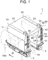
- FIG. 1 is a perspective view of a pest control vehicle 1.
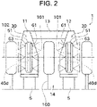
- FIG. 2 is a schematic back view illustrating a configuration of a back surface of the pest control vehicle 1.
- a direction in which the pest control vehicle 1 travels when spraying chemical liquid is determined as the front side, and the front, back, left, and right sides are defined. Accordingly, a vehicle width direction coincides with the left-right direction, and a vehicle length direction coincides with the front-back direction.
- a left and right pair (or front and back pair) of components disposed in the pest control vehicle 1 are designated with the same reference number, and descriptions thereof may be omitted or simplified.
- the pest control vehicle 1 is a vehicle that sprays chemical liquid on plants 100 (spray target objects, work target objects) raised on a farm or the like.
- the plants 100 are, for example, orchard trees but may be vegetables.
- the pest control vehicle 1 includes crawler traveling portions 5 and a vehicle body 10.
- the crawler traveling portions 5 are each a hydraulic type, and hydraulic oil is supplied to a hydraulic motor (not illustrated) to rotate a drive sprocket. Accordingly, crawlers wound on the drive sprockets, driving wheels, or the like rotate to allow the pest control vehicle 1 to travel. Further, by differentiating driving speeds of the left and right crawler traveling portions 5, the pest control vehicle 1 can turn. Furthermore, by differentiating driving directions of the left and right crawler traveling portions 5, the pest control vehicle 1 can turn without changing the position.
- the vehicle body 10 is supported by the crawler traveling portions 5.
- the vehicle body 10 includes a left vehicle body 11, a right vehicle body 12, and an upper vehicle body 13.
- the left vehicle body 11 is mainly supported by the left crawler traveling portion 5.
- the left vehicle body 11 includes a frame and a cover covering the frame.
- the right vehicle body 12 is mainly supported by the right crawler traveling portion 5.
- the right vehicle body 12 includes a frame and a cover covering the frame.
- Upper portions of the left vehicle body 11 and the right vehicle body 12 are connected by the upper vehicle body 13.
- a passage space 14 surrounded by the left vehicle body 11, the right vehicle body 12, and the upper vehicle body 13 is formed.
- the passage space 14 is a space in which components are not disposed from the ground to a predetermined height and through which the plants 100 can pass when the pest control vehicle 1 travels.
- the left and right crawler traveling portions 5 travel while sandwiching the plants 100 in the left-right direction.
- the pest control vehicle 1 travels in the farm while straddling the plants 100.
- An engine 21 is disposed in the left vehicle body 11.
- the engine 21 generates drive force to allow the pest control vehicle 1 to travel (power to operate a hydraulic motor). Note that the engine 21 may be disposed in the right vehicle body 12.
- a chemical liquid tank 22 is disposed in the right vehicle body 12. Chemical liquid is stored in the chemical liquid tank 22.
- the chemical liquid stored in the chemical liquid tank 22 is medical agent having a function such as moth proofing, insect killing, or weeding. Note that the chemical liquid tank 22 may be disposed in the left vehicle body 11.
- injection units 30 are respectively disposed on back surfaces of the left vehicle body 11 and the right vehicle body 12. Each of the injection units 30 sprays the chemical liquid to both the left and right sides. Consequently, as illustrated in FIG. 2 , the pest control vehicle 1 can simultaneously spray the chemical liquid on a right portion of the plant 100 on the left side of the pest control vehicle 1, both left and right portions of the plant 100 passing through the passage space 14, and a left portion of the plant 100 on the right side of the pest control vehicle 1.
- the injection units 30 may be disposed on front surfaces of the left vehicle body 11 and the right vehicle body 12. The configuration of the injection unit 30 will be described below in detail.
- the pest control vehicle 1 is configured to autonomously travel in the farm. In other words, the pest control vehicle 1 detects its current position by using GNSS or the like. Additionally, an autonomous travel route is created in advance based on position information of the farm. With such a configuration, the pest control vehicle 1 sprays the chemical liquid on the plants 100 while autonomously traveling based on the current position and the autonomous travel route.
- the pest control vehicle 1 is not limited to a vehicle that autonomously travels.
- the pest control vehicle 1 may be, for example, a vehicle that travels by remote control.
- the remote control is referred to as control in which an operation by an operator located away from the pest control vehicle 1 (that is, an operator not riding on the pest control vehicle 1) allows the pest control vehicle 1 to travel or allows the pest control vehicle 1 to spray the chemical liquid.
- the left and right injection units 30 are configured in the same manner or are configured symmetrically with respect to a plane passing through the center in the vehicle width direction. Therefore, the left and right injection units 30 will be summarized and described below.
- the injection unit 30 of the present embodiment injects both the chemical liquid and air.
- the injection of the air supports the chemical liquid to be sprayed. Specifically, the chemical liquid is splashed by the air, and thus the chemical liquid can be uniformly applied. In particular, in the case of spraying the chemical liquid on leaves of the plants 100, the leaves sway with the air; therefore, the chemical liquid can be sprayed uniformly on the front and back of the leaves. Additionally, the air to be injected is increased, and thus a distance in which the chemical liquid is sprayed can be increased. Note that components for injecting the air are not essential components and can be omitted.
- the injection unit 30 includes, as components for injecting the air, a blower duct 51, a blower hose 52, a blower device 53, and air injection portions 54.
- the blower duct 51 is attached via a rotation support portion 40 to the vehicle body 10.
- the rotation support portion 40 includes a bearing and the like and allows the blower duct 51 to be attached to the vehicle body 10 such that the blower duct 51 can rotate relative to the vehicle body 10. Note that the configuration of the rotation support portion 40 will be described below in detail.
- the blower duct 51 is disposed to extend in the up-down direction.
- the blower duct 51 is an elongated member, and is disposed such that its longitudinal direction substantially coincides with the up-down direction (vehicle height direction). Note that, for example, even when the longitudinal direction of the blower duct 51 is deviated from the up-down direction by few angles, the longitudinal direction of the blower duct 51 is defined to substantially coincide with the up-down direction (that is, the blower duct 51 extends in the up-down direction).
- a space through which air (particularly, compressed air) for supporting the chemical liquid to be sprayed passes is formed inside the blower duct 51.
- the blower hose 52 that supplies air is connected to the blower duct 51. Specifically, an upper end of the blower duct 51 is opened.
- the blower duct 51 is configured such that a coupler of the blower hose 52 is connectable to the upper end.
- the blower hose 52 is connected to the blower device 53.
- a portion of the blower hose 52 is a flexible hose that is extendable.
- the blower device 53 sucks air in or sends the air to generate compressed air and send the compressed air.
- the blower device 53 is disposed on the level higher than the blower duct 51.
- One blower device 53 is disposed on the left vehicle body 11 and one blower device 53 is disposed on the right vehicle body, and thus a total of two blower devices 53 are disposed.
- the blower device 53 is disposed such that a portion is exposed from the vehicle body to suck outside air in.
- a plurality of air injection portions 54 are disposed in the blower duct 51.
- the air injection portions 54 are each a hole through which air is injected. Note that the air injection portion 54 may be a nozzle.
- the air injection portions 54 are disposed side by side in the up-down direction.
- the air injection portions 54 are formed on left and right surfaces of the blower duct 51.
- the injection unit 30 includes chemical liquid ducts 61 from which the chemical liquid is injected, chemical liquid hoses 62, and chemical liquid injection portions 63.
- a left and right pair of chemical liquid ducts 61 that inject the chemical liquid toward the left side and the right side are attached to the blower duct 51.
- the pest control vehicle 1 of the present embodiment includes four chemical liquid ducts 61.
- the chemical liquid ducts 61 are supported via the blower duct 51 on the vehicle body 10 but may be supported on the vehicle body 10 without the blower duct 51.
- the chemical liquid ducts 61 are each disposed to extend in the up-down direction, and the longitudinal direction of the chemical liquid duct 61 is parallel to the longitudinal direction of the blower duct 51.
- a space through which the chemical liquid stored in the chemical liquid tank 22 passes is formed inside the chemical liquid duct 61.
- the chemical liquid hoses 62 that supplies the chemical liquid from the chemical liquid tank 22 are respectively connected to the chemical liquid ducts 61. Specifically, an upper end of the chemical liquid duct 61 is opened.
- the chemical liquid duct 61 is configured such that a coupler of the chemical liquid hose 62 is connectable to the upper end.
- a pump (not illustrated) is disposed in a pathway that connects the chemical liquid duct 61 to the chemical liquid tank 22. The chemical liquid in the chemical liquid tank 22 is pumped by the pump to the chemical liquid duct 61.
- a pathway of the chemical liquid hose 62 may be disposed in any manner but is preferably disposed so as not to pass through the passage space 14.
- the chemical liquid hose 62 connected to the left chemical liquid duct 61 is preferably connected through the upper vehicle body 13 to the chemical liquid tank 22.
- a plurality of chemical liquid injection portions 63 are disposed on the chemical liquid duct 61.
- the chemical liquid injection portions 63 are each a nozzle from which the chemical liquid is injected.
- the chemical liquid injection portions 63 are disposed side by side in the up-down direction.
- the chemical liquid injection portions 63 are disposed in a direction enabling the aforementioned chemical liquid to be sprayed.
- the chemical liquid injection portions 63 are disposed at the left side of the left chemical liquid duct 61, and the chemical liquid injection portions 63 are disposed at the right side of the right chemical liquid duct 61. The same applies to the right vehicle body 12.
- the number of air injection portions 54 disposed in the single injection unit 30 is greater than the number of chemical liquid injection portions 63 disposed in the single injection unit 30.
- the chemical liquid can be uniformly sprayed while the number of chemical liquid injection portions 63 is suppressed.
- the number of chemical liquid injection portions 63 may be equal to the number of air injection portions 54 or the number of chemical liquid injection portions 63 may be greater than the number of air injection portions 54.
- the rotation support portion 40 supports the blower duct 51 such that the blower duct 51 can rotate about a rotation axis 101.
- the rotation axis 101 is substantially the same direction as the front-back direction.
- the chemical liquid ducts 61 and the chemical liquid injection portions 63 are attached to the blower duct 51. Therefore, by rotating the blower duct 51, the chemical liquid ducts 61 and the chemical liquid injection portions 63 also integrally rotate.
- the chemical liquid ducts 61 are connected to the blower device 53 by the chemical liquid hoses 62 including flexible hoses. Consequently, even when the chemical liquid ducts 61 rotate relative to the vehicle body 10, the displacement can be absorbed by the chemical liquid hoses 62.
- the rotation support portion 40 includes a base portion 40a, a slide portion 40b, a relay member 40c, a bearing 40d, and a fixation member 40e.
- the base portion 40a is fixed to the left vehicle body 11 or the right vehicle body 12.
- the slide portion 40b is configured to switch between a first state in which the slide portion 40b can slide relative to the base portion 40a in the left-right direction and a second state in which sliding of the slide portion 40b is restricted.
- attachment holes 401 are formed side by side in the left-right direction and at predetermined intervals L in the base portion 40a.
- Attachment holes 402 are formed in the slide portion 40b at the same intervals L or at intervals, each of which is integral multiple of L.
- the slide portion 40b By aligning the attachment holes 401 of the base portion 40a with the attachment holes 402 of the slide portion 40b and fixing the slide portion 40b to the base portion 40a with the fixation member 40e, the slide portion 40b is brought into a non-slidable state to the base portion 40a (the second state). Then, by removing the fixation member 40e, the slide portion 40b is brought into a slidable state to the base portion 40a (the first state).
- the slide portion 40b is slid in the left-right direction to the base portion 40a to be mounted at a desired position, thereafter being fixed to the base portion 40a with the attachment holes 401 of the base portion 40a aligned with the attachment holes 402 of the slide portion 40b.
- the position in the left-right direction of the blower duct 51 (simultaneously, the position in the left-right direction of the chemical liquid injection portions 63) can be changed.
- An outer race of the bearing 40d is fixed via the relay member 40c to the slide portion 40b.
- the blower duct 51 is fixed via the relay member 40c to an inner race of the bearing 40d.
- the rotation support portion 40 supports the blower duct 51 such that the blower duct 51 is rotatable. Therefore, the blower duct 51, the air injection portions 54, the chemical liquid ducts 61, the chemical liquid injection portions 63, and the like can integrally rotate relative to the vehicle body 10.
- the height of the bearing 40d i.e., the height of the rotation axis 101
- the center in the up-down direction of the chemical liquid duct 61 i.e., an imaginary line 102 illustrated in FIG. 2 . Therefore, when being inclined, the pest control vehicle 1 can rotate, under its own weight, the blower ducts 51, the air injection portions 54, the chemical liquid ducts 61, the chemical liquid injection portions 63, and the like integrally relative to the vehicle body 10.
- a pest control vehicle 1A is basically in a vertical position relative to the ground. In contrast, the plants 100 vertically grow. Therefore, the positional relationship between the pest control vehicle 1A and the plant 100 when pest control is performed on the inclined ground is different from that when pest control is performed on the flat ground.
- the plants 100 are inclined to the pest control vehicle 1A. Accordingly, injection units 30A are inclined to the plants 100. As a result, the distance between the chemical liquid injection portions and the plant 100 is too close or too far, and the chemical liquid cannot be sprayed uniformly on the plant 100. Further, a vehicle body 10A is inclined to the plants 100. As a result, an appropriate distance between an inner wall surface of the vehicle body 10A and the plant 100 cannot be maintained, and according to the circumstances, the vehicle body 10A may come into contact with the plant 100.
- the pest control vehicle 1 is inclined, and thus the blower ducts 51, the chemical liquid ducts 61, and the like are rotated by the bearings 40d. Accordingly, the longitudinal direction of the blower duct 51 and the chemical liquid duct 61 extends along the vertical direction (see FIG. 5 ). In other words, even when the pest control vehicle 1 travels on an inclined ground, the injection units 30 do not tilt relative to the plants 100. As a result, variations in the distance between the chemical liquid injection portions 63 and the plant 100 are less likely to occur.
- a left inner wall surface of the left vehicle body 11 (a surface facing the passage space 14) includes a first left inclined surface 11a.
- the first left inclined surface 11a is a surface inclined to the left side (outer side in the vehicle width direction) toward the top of the pest control vehicle 1.
- a right inner wall surface of the right vehicle body 12 (a surface facing the passage space 14) includes a first right inclined surface 12a.
- the first right inclined surface 12a is a surface inclined to the right side (outer side in the vehicle width direction) toward the top of the pest control vehicle 1.
- the first left inclined surface 11a and the first right inclined surface 12a are formed, and thus the distance between the plant 100 in the passage space 14 and the vehicle body 10 can be appropriately maintained.
- the left-right position of the chemical liquid duct 61 and the like can be changed by the rotation support portion 40.
- the left-right position of the chemical liquid duct 61 is changed, the left-right position of the bearing 40d (that is, the left-right position of the rotation axis 101) is changed at the same time.
- the left-right position is adjusted by using the rotation support portion 40, and thus the position of the rotation axis 101 can be adjusted. Accordingly, for example, the left-right position of the rotation axis 101 is adjusted based on the inclination angle and the size, shape, or the like of the plant 100, and thus the positional relationship between the chemical liquid injection portions 63 and the plant 100 can be more appropriately set.
- a left outer wall surface of the left vehicle body 11 (a surface facing the outer side in the vehicle width direction) includes a second left inclined surface 11b.
- the second left inclined surface 11b is a surface inclined to the right side (inner side in the vehicle width direction) toward the top of the pest control vehicle 1.
- a right outer wall surface of the right vehicle body 12 (a surface facing the outer side in the vehicle width direction) includes a second right inclined surface 12b.
- the second right inclined surface 12b is a surface inclined closer to the left side (inner side in the vehicle width direction) toward the top of the pest control vehicle 1.
- the second left inclined surface 11b and the second right inclined surface 12b are formed, and thus the distance between each of the plants 100 located on the left and right sides of the vehicle body 10 and the vehicle body 10 can be appropriately maintained.
- the pest control vehicle 1 of the present embodiment includes the vehicle body 10, the crawler traveling portions 5, the chemical liquid ducts 61, the chemical liquid injection portions 63, and the rotation support portions 40.
- the crawler traveling portions 5 allow the vehicle body 10 to travel.
- the chemical liquid ducts 61 are attached to the vehicle body 10 and are disposed to extend in the up-down direction, and the chemical liquid for pest control flows through the chemical liquid ducts 61.
- the chemical liquid injection portions 63 are connected to the chemical liquid ducts 61, and the plurality of chemical liquid injection portions 63 are arranged side by side in the up-down direction.
- the rotation support portion 40 supports the chemical liquid ducts 61, and the chemical liquid ducts 61 are attached via the rotation support portion 40 to the vehicle body 10 such that the chemical liquid ducts 61 can rotate relative to the vehicle body 10 about the front-back direction as the rotation axis 101.
- the height of the rotation axis 101 of the rotation support portion 40 is above the center in the up-down direction of the chemical liquid duct 61.
- the chemical liquid ducts 61 and the chemical liquid injection portions 63 can rotate under own weight of the chemical liquid ducts 61.
- the rotation support portion 40 includes the base portion 40a and the slide portion 40b.
- the base portion 40a is attached to the vehicle body 10.
- the slide portion 40b is switchable between a state in which the slide portion 40b is slidable in the left-right direction to the base portion 40a and a state in which sliding of the slide portion 40b is restricted, and the slide portion 40b supports the chemical liquid ducts 61. By sliding the slide portion 40b, the left-right position of the chemical liquid injection portion 63 is changed.
- the position of the rotation axis 101 is adjusted based on the angle of the inclined ground or the shape or the like of the plant 100, and thus the positional relationship between the chemical liquid injection portions 63 and the plant 100 can be more appropriately maintained.
- the vehicle body 10 includes the left vehicle body 11 and the right vehicle body 12, and the passage space 14 through which a spray target object passes is formed between the left vehicle body 11 and the right vehicle body 12.
- the left inner wall surface of the left vehicle body 11 facing the passage space 14 includes an inclined portion (the first left inclined surface 11a) that is inclined closer to the left side toward the top.
- the right inner wall surface of the right vehicle body 12 facing the passage space 14 includes an inclined portion (the first right inclined surface 12a) that is inclined closer to the right side toward the top.
- the pest control vehicle when traveling on the inclined ground, the pest control vehicle is less likely to come into contact with a spray target object passing through the passage space.
- the left outer wall surface of the left vehicle body 11 facing the outer side in the left-right direction includes an inclined portion (the second left inclined surface 11b) that is inclined closer to the right side toward the top.
- the right outer wall surface of the right vehicle body 12 facing the outer side in the left-right direction includes an inclined portion (the second right inclined surface 12b) that is inclined closer to the left side toward the top.
- the pest control vehicle when traveling on the inclined ground, the pest control vehicle is less likely to come into contact with a spray target object located at the outer side in the left-right direction of the pest control vehicle.
- the pest control vehicle 1 of the present embodiment is configured such that the air is injected to support the chemical liquid to be sprayed, but the configuration to inject the air may be omitted.
- the chemical liquid ducts 61 of the present embodiment are supported by the blower duct 51, but the chemical liquid ducts 61 may be supported by the rotation support portion 40 or the like without being supported by the blower duct 51.
- the inner wall surface of the vehicle body 10 of the present embodiment includes a vertical portion and an inclined portion. Alternatively, the entire inner wall surface of the vehicle body 10 may be inclined.
- the injection unit 30 is configured to rotate under its own weight to be oriented in the vertical direction.
- the injection unit 30 may be rotated by using an actuator such as a motor.
- the pest control vehicle 1 of the aforementioned embodiment travels with the crawlers but may travel with driving wheels.
Landscapes
- Life Sciences & Earth Sciences (AREA)
- Engineering & Computer Science (AREA)
- Insects & Arthropods (AREA)
- Pest Control & Pesticides (AREA)
- Wood Science & Technology (AREA)
- Zoology (AREA)
- Environmental Sciences (AREA)
- Catching Or Destruction (AREA)
- Special Spraying Apparatus (AREA)
- Spray Control Apparatus (AREA)
Abstract
Description
- The present invention mainly relates to a pest control vehicle that sprays chemical liquid for pest control.
-
Japanese Patent Application Publication No. 2020-152285 - Patent Document 1:
Japanese Patent Application Publication No. 2020-152285 - Plants (spray target objects) planted on an inclined ground generally grow along a vertical direction. Therefore, when the pest control vehicle travels on the inclined ground, the direction of the pest control vehicle and the direction of the plants are different from those in the case of traveling on a flat ground. As a result, the positional relationship between the nozzle unit and the plant may not be appropriate.
- The present invention is made in view of the above circumstance, and a main object of the present invention is to provide a pest control vehicle that can appropriately maintain the positional relationship between chemical liquid injection portions and an spray target object even when spraying chemical liquid while traveling on an inclined ground.
- The problem to be solved by the present invention is as described above. Next, means for solving the problem and effects thereof will be described.
- According to a first aspect of the present invention, a pest control vehicle configured as below is provided. In other words, the pest control vehicle includes a vehicle body, traveling portions, a chemical liquid tank, chemical liquid ducts, chemical liquid injection portions, and rotation support portions. The traveling portions allow the vehicle body to travel. The chemical liquid ducts are attached to the vehicle body and are disposed to extend in the up-down direction, and the chemical liquid for pest control flows through the chemical liquid ducts. The chemical liquid injection portions are connected to the chemical liquid duct, and the plurality of chemical liquid injection portions are arranged side by side in the up-down direction. The rotation support portion supports the chemical liquid ducts and attaches the chemical liquid ducts to the vehicle body to allow the chemical liquid ducts to rotate relative to the vehicle body about a front-back direction as a rotation axis.
- Thus, even when the chemical liquid is sprayed during traveling on an inclined ground, the positional relationship of the chemical liquid ducts and the chemical liquid injection portions to a spray target object can be appropriately maintained.
- In the pest control vehicle, a height of the rotation axis of the rotation support portion is above a center in the up-down direction of the chemical liquid duct.
- Thus, at the time of traveling on an inclined ground, the chemical liquid ducts can rotate under own weight of the chemical liquid ducts.
- In the pest control vehicle, the following configurations are preferably provided. In other words, the rotation support portion includes a base portion and a slide portion. The base portion is attached to the vehicle body. The slide portion is switchable between a state where the slide portion slides to the base portion in a left-right direction and a state where sliding of the slide portion is restricted, and the slide portion supports the chemical liquid ducts. The slide portion is slid to change a position in the left-right direction of the chemical liquid injection portions.
- Accordingly, the position of the rotation axis is adjusted based on the angle of an inclined ground or the shape or the like of the spray target object, and thus the positional relationship between the chemical liquid injection portions and the spray target object can be more appropriately maintained.
- In the pest control vehicle, the following configurations are preferably provided. In other words, the vehicle body includes a left vehicle body and a right vehicle body, and a passage space through which a spray target object passes is formed between the left vehicle body and the right vehicle body. A left inner wall surface of the left vehicle body, which faces the passage space, includes an inclined portion that is inclined closer to a left side toward a top. A right inner wall surface of the right vehicle body, which faces the passage space, includes an inclined portion that is inclined closer to a right side toward the top.
- Thus, when traveling on the inclined ground, the pest control vehicle is less likely to come into contact with the spray target object passing through the passage space.
- According to a second aspect of the present invention, a pest control vehicle configured as below is provided. In other words, the pest control vehicle includes a vehicle body, traveling portions, and chemical liquid injection portions. The vehicle body includes a left vehicle body and a right vehicle body, and a passage space through which a spray target object passes is formed between the left vehicle body and the right vehicle body. The traveling portions allow the vehicle body to travel. The chemical liquid injection portions inject chemical liquid for pest control. A left inner wall surface of the left vehicle body, which faces the passage space, includes an inclined portion that is inclined closer to a left side toward a top. A right inner wall surface of the right vehicle body, which faces the passage space, includes an inclined portion that is inclined closer to a right side toward the top.
- Thus, when traveling on the inclined ground, the pest control vehicle is less likely to come into contact with the spray target object passing through the passage space.
- In the pest control vehicle, the following configurations are preferably provided. In other words, a left outer wall surface of the left vehicle body, which faces an outer side in a left-right direction, includes an inclined portion that is inclined closer to the right side toward the top. A right outer wall surface of the right vehicle body, which faces an outer side in the left-right direction, includes an inclined portion that is inclined closer to the left side toward the top.
- Thus, when traveling on the inclined ground, the pest control vehicle is less likely to come into contact with a spray target object located at the outer side in the left-right direction of the pest control vehicle.
-
-
FIG. 1 is a perspective view of a pest control vehicle according to a first embodiment of the present invention. -
FIG. 2 is a schematic back view illustrating a configuration of a back surface of the pest control vehicle. -
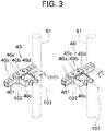
FIG. 3 is a perspective view illustrating an operation of a position adjustment mechanism. -
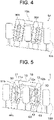
FIG. 4 is a schematic back view illustrating a state where a pest control vehicle of the prior art sprays chemical liquid while traveling on an inclined ground. -
FIG. 5 is a schematic back view illustrating a state where the pest control vehicle according to the present embodiment sprays chemical liquid while traveling on an inclined ground. - Next, embodiments of the present invention will be described with reference to the drawings.
FIG. 1 is a perspective view of apest control vehicle 1.FIG. 2 is a schematic back view illustrating a configuration of a back surface of thepest control vehicle 1. In the descriptions below, a direction in which thepest control vehicle 1 travels when spraying chemical liquid is determined as the front side, and the front, back, left, and right sides are defined. Accordingly, a vehicle width direction coincides with the left-right direction, and a vehicle length direction coincides with the front-back direction. In addition, a left and right pair (or front and back pair) of components disposed in thepest control vehicle 1 are designated with the same reference number, and descriptions thereof may be omitted or simplified. - The
pest control vehicle 1 is a vehicle that sprays chemical liquid on plants 100 (spray target objects, work target objects) raised on a farm or the like. Theplants 100 are, for example, orchard trees but may be vegetables. As illustrated inFIGS. 1 and2 , thepest control vehicle 1 includescrawler traveling portions 5 and avehicle body 10. - The
crawler traveling portions 5 are each a hydraulic type, and hydraulic oil is supplied to a hydraulic motor (not illustrated) to rotate a drive sprocket. Accordingly, crawlers wound on the drive sprockets, driving wheels, or the like rotate to allow thepest control vehicle 1 to travel. Further, by differentiating driving speeds of the left and rightcrawler traveling portions 5, thepest control vehicle 1 can turn. Furthermore, by differentiating driving directions of the left and rightcrawler traveling portions 5, thepest control vehicle 1 can turn without changing the position. - The
vehicle body 10 is supported by thecrawler traveling portions 5. Thevehicle body 10 includes aleft vehicle body 11, aright vehicle body 12, and anupper vehicle body 13. - The
left vehicle body 11 is mainly supported by the leftcrawler traveling portion 5. Theleft vehicle body 11 includes a frame and a cover covering the frame. Theright vehicle body 12 is mainly supported by the rightcrawler traveling portion 5. Theright vehicle body 12 includes a frame and a cover covering the frame. Upper portions of theleft vehicle body 11 and theright vehicle body 12 are connected by theupper vehicle body 13. Thus, apassage space 14 surrounded by theleft vehicle body 11, theright vehicle body 12, and theupper vehicle body 13 is formed. - The
passage space 14 is a space in which components are not disposed from the ground to a predetermined height and through which theplants 100 can pass when thepest control vehicle 1 travels. Thus, the left and rightcrawler traveling portions 5 travel while sandwiching theplants 100 in the left-right direction. In other words, thepest control vehicle 1 travels in the farm while straddling theplants 100. - An
engine 21 is disposed in theleft vehicle body 11. Theengine 21 generates drive force to allow thepest control vehicle 1 to travel (power to operate a hydraulic motor). Note that theengine 21 may be disposed in theright vehicle body 12. - A
chemical liquid tank 22 is disposed in theright vehicle body 12. Chemical liquid is stored in thechemical liquid tank 22. The chemical liquid stored in thechemical liquid tank 22 is medical agent having a function such as moth proofing, insect killing, or weeding. Note that thechemical liquid tank 22 may be disposed in theleft vehicle body 11. - Additionally,
injection units 30 are respectively disposed on back surfaces of theleft vehicle body 11 and theright vehicle body 12. Each of theinjection units 30 sprays the chemical liquid to both the left and right sides. Consequently, as illustrated inFIG. 2 , thepest control vehicle 1 can simultaneously spray the chemical liquid on a right portion of theplant 100 on the left side of thepest control vehicle 1, both left and right portions of theplant 100 passing through thepassage space 14, and a left portion of theplant 100 on the right side of thepest control vehicle 1. Note that theinjection units 30 may be disposed on front surfaces of theleft vehicle body 11 and theright vehicle body 12. The configuration of theinjection unit 30 will be described below in detail. - The
pest control vehicle 1 is configured to autonomously travel in the farm. In other words, thepest control vehicle 1 detects its current position by using GNSS or the like. Additionally, an autonomous travel route is created in advance based on position information of the farm. With such a configuration, thepest control vehicle 1 sprays the chemical liquid on theplants 100 while autonomously traveling based on the current position and the autonomous travel route. - Note that the
pest control vehicle 1 is not limited to a vehicle that autonomously travels. Thepest control vehicle 1 may be, for example, a vehicle that travels by remote control. The remote control is referred to as control in which an operation by an operator located away from the pest control vehicle 1 (that is, an operator not riding on the pest control vehicle 1) allows thepest control vehicle 1 to travel or allows thepest control vehicle 1 to spray the chemical liquid. - Next, the
injection unit 30 will be described in detail with reference toFIGS. 1 to 3 . The left andright injection units 30 are configured in the same manner or are configured symmetrically with respect to a plane passing through the center in the vehicle width direction. Therefore, the left andright injection units 30 will be summarized and described below. - The
injection unit 30 of the present embodiment injects both the chemical liquid and air. The injection of the air supports the chemical liquid to be sprayed. Specifically, the chemical liquid is splashed by the air, and thus the chemical liquid can be uniformly applied. In particular, in the case of spraying the chemical liquid on leaves of theplants 100, the leaves sway with the air; therefore, the chemical liquid can be sprayed uniformly on the front and back of the leaves. Additionally, the air to be injected is increased, and thus a distance in which the chemical liquid is sprayed can be increased. Note that components for injecting the air are not essential components and can be omitted. - The
injection unit 30 includes, as components for injecting the air, ablower duct 51, a blower hose 52, ablower device 53, andair injection portions 54. - The
blower duct 51 is attached via arotation support portion 40 to thevehicle body 10. Therotation support portion 40 includes a bearing and the like and allows theblower duct 51 to be attached to thevehicle body 10 such that theblower duct 51 can rotate relative to thevehicle body 10. Note that the configuration of therotation support portion 40 will be described below in detail. - The
blower duct 51 is disposed to extend in the up-down direction. In other words, theblower duct 51 is an elongated member, and is disposed such that its longitudinal direction substantially coincides with the up-down direction (vehicle height direction). Note that, for example, even when the longitudinal direction of theblower duct 51 is deviated from the up-down direction by few angles, the longitudinal direction of theblower duct 51 is defined to substantially coincide with the up-down direction (that is, theblower duct 51 extends in the up-down direction). - A space through which air (particularly, compressed air) for supporting the chemical liquid to be sprayed passes is formed inside the
blower duct 51. The blower hose 52 that supplies air is connected to theblower duct 51. Specifically, an upper end of theblower duct 51 is opened. Theblower duct 51 is configured such that a coupler of the blower hose 52 is connectable to the upper end. The blower hose 52 is connected to theblower device 53. In the present embodiment, a portion of the blower hose 52 is a flexible hose that is extendable. Thus, in a case where the position or the like of theblower duct 51 is adjusted or in a case where rattling or the like occurs, countermeasures can be taken. - The
blower device 53 sucks air in or sends the air to generate compressed air and send the compressed air. Theblower device 53 is disposed on the level higher than theblower duct 51. Oneblower device 53 is disposed on theleft vehicle body 11 and oneblower device 53 is disposed on the right vehicle body, and thus a total of twoblower devices 53 are disposed. Theblower device 53 is disposed such that a portion is exposed from the vehicle body to suck outside air in. - A plurality of
air injection portions 54 are disposed in theblower duct 51. Theair injection portions 54 are each a hole through which air is injected. Note that theair injection portion 54 may be a nozzle. Theair injection portions 54 are disposed side by side in the up-down direction. Theair injection portions 54 are formed on left and right surfaces of theblower duct 51. - The
injection unit 30 includeschemical liquid ducts 61 from which the chemical liquid is injected, chemicalliquid hoses 62, and chemicalliquid injection portions 63. - A left and right pair of chemical
liquid ducts 61 that inject the chemical liquid toward the left side and the right side are attached to theblower duct 51. Accordingly, thepest control vehicle 1 of the present embodiment includes fourchemical liquid ducts 61. Additionally, in the present embodiment, thechemical liquid ducts 61 are supported via theblower duct 51 on thevehicle body 10 but may be supported on thevehicle body 10 without theblower duct 51. Thechemical liquid ducts 61 are each disposed to extend in the up-down direction, and the longitudinal direction of the chemicalliquid duct 61 is parallel to the longitudinal direction of theblower duct 51. - A space through which the chemical liquid stored in the
chemical liquid tank 22 passes is formed inside the chemicalliquid duct 61. The chemicalliquid hoses 62 that supplies the chemical liquid from thechemical liquid tank 22 are respectively connected to thechemical liquid ducts 61. Specifically, an upper end of the chemicalliquid duct 61 is opened. The chemicalliquid duct 61 is configured such that a coupler of the chemicalliquid hose 62 is connectable to the upper end. Additionally, a pump (not illustrated) is disposed in a pathway that connects the chemicalliquid duct 61 to thechemical liquid tank 22. The chemical liquid in thechemical liquid tank 22 is pumped by the pump to the chemicalliquid duct 61. Note that a pathway of the chemicalliquid hose 62 may be disposed in any manner but is preferably disposed so as not to pass through thepassage space 14. In other words, the chemicalliquid hose 62 connected to the left chemicalliquid duct 61 is preferably connected through theupper vehicle body 13 to thechemical liquid tank 22. - A plurality of chemical
liquid injection portions 63 are disposed on the chemicalliquid duct 61. The chemicalliquid injection portions 63 are each a nozzle from which the chemical liquid is injected. The chemicalliquid injection portions 63 are disposed side by side in the up-down direction. The chemicalliquid injection portions 63 are disposed in a direction enabling the aforementioned chemical liquid to be sprayed. Specifically, on theinjection unit 30 disposed on theleft vehicle body 11, the chemicalliquid injection portions 63 are disposed at the left side of the left chemicalliquid duct 61, and the chemicalliquid injection portions 63 are disposed at the right side of the rightchemical liquid duct 61. The same applies to theright vehicle body 12. - In the present embodiment, the number of
air injection portions 54 disposed in thesingle injection unit 30 is greater than the number of chemicalliquid injection portions 63 disposed in thesingle injection unit 30. Thus, the chemical liquid can be uniformly sprayed while the number of chemicalliquid injection portions 63 is suppressed. Note that the number of chemicalliquid injection portions 63 may be equal to the number ofair injection portions 54 or the number of chemicalliquid injection portions 63 may be greater than the number ofair injection portions 54. - Next, the configuration of the
rotation support portion 40 will be described in detail with reference toFIG. 3 . - The
rotation support portion 40 supports theblower duct 51 such that theblower duct 51 can rotate about arotation axis 101. Therotation axis 101 is substantially the same direction as the front-back direction. Additionally, thechemical liquid ducts 61 and the chemicalliquid injection portions 63 are attached to theblower duct 51. Therefore, by rotating theblower duct 51, thechemical liquid ducts 61 and the chemicalliquid injection portions 63 also integrally rotate. Note that thechemical liquid ducts 61 are connected to theblower device 53 by thechemical liquid hoses 62 including flexible hoses. Consequently, even when thechemical liquid ducts 61 rotate relative to thevehicle body 10, the displacement can be absorbed by thechemical liquid hoses 62. - As illustrated in
FIG. 3 , therotation support portion 40 includes abase portion 40a, aslide portion 40b, arelay member 40c, abearing 40d, and afixation member 40e. - The
base portion 40a is fixed to theleft vehicle body 11 or theright vehicle body 12. Theslide portion 40b is configured to switch between a first state in which theslide portion 40b can slide relative to thebase portion 40a in the left-right direction and a second state in which sliding of theslide portion 40b is restricted. Specifically, attachment holes 401 are formed side by side in the left-right direction and at predetermined intervals L in thebase portion 40a. Attachment holes 402 are formed in theslide portion 40b at the same intervals L or at intervals, each of which is integral multiple of L. By aligning the attachment holes 401 of thebase portion 40a with the attachment holes 402 of theslide portion 40b and fixing theslide portion 40b to thebase portion 40a with thefixation member 40e, theslide portion 40b is brought into a non-slidable state to thebase portion 40a (the second state). Then, by removing thefixation member 40e, theslide portion 40b is brought into a slidable state to thebase portion 40a (the first state). - With such a configuration, the
slide portion 40b is slid in the left-right direction to thebase portion 40a to be mounted at a desired position, thereafter being fixed to thebase portion 40a with the attachment holes 401 of thebase portion 40a aligned with the attachment holes 402 of theslide portion 40b. As described above, the position in the left-right direction of the blower duct 51 (simultaneously, the position in the left-right direction of the chemical liquid injection portions 63) can be changed. - An outer race of the
bearing 40d is fixed via therelay member 40c to theslide portion 40b. Also, theblower duct 51 is fixed via therelay member 40c to an inner race of thebearing 40d. With the above configuration, therotation support portion 40 supports theblower duct 51 such that theblower duct 51 is rotatable. Therefore, theblower duct 51, theair injection portions 54, thechemical liquid ducts 61, the chemicalliquid injection portions 63, and the like can integrally rotate relative to thevehicle body 10. - As illustrated in
FIG. 2 , the height of thebearing 40d (i.e., the height of the rotation axis 101) is above the center in the up-down direction of the chemical liquid duct 61 (i.e., animaginary line 102 illustrated inFIG. 2 ). Therefore, when being inclined, thepest control vehicle 1 can rotate, under its own weight, theblower ducts 51, theair injection portions 54, thechemical liquid ducts 61, the chemicalliquid injection portions 63, and the like integrally relative to thevehicle body 10. - Next, pest control on an inclined ground will be described with reference to
FIGS. 4 and 5 . - Initially, referring to
FIG. 4 , problems in a case where pest control is performed on an inclined ground by using a conventional pest control vehicle will be described. As illustrated inFIG. 4 , apest control vehicle 1A is basically in a vertical position relative to the ground. In contrast, theplants 100 vertically grow. Therefore, the positional relationship between thepest control vehicle 1A and theplant 100 when pest control is performed on the inclined ground is different from that when pest control is performed on the flat ground. - Specifically, as shown in
FIG. 4 , theplants 100 are inclined to thepest control vehicle 1A. Accordingly,injection units 30A are inclined to theplants 100. As a result, the distance between the chemical liquid injection portions and theplant 100 is too close or too far, and the chemical liquid cannot be sprayed uniformly on theplant 100. Further, avehicle body 10A is inclined to theplants 100. As a result, an appropriate distance between an inner wall surface of thevehicle body 10A and theplant 100 cannot be maintained, and according to the circumstances, thevehicle body 10A may come into contact with theplant 100. - In this regard, in the present embodiment, the
pest control vehicle 1 is inclined, and thus theblower ducts 51, thechemical liquid ducts 61, and the like are rotated by thebearings 40d. Accordingly, the longitudinal direction of theblower duct 51 and the chemicalliquid duct 61 extends along the vertical direction (seeFIG. 5 ). In other words, even when thepest control vehicle 1 travels on an inclined ground, theinjection units 30 do not tilt relative to theplants 100. As a result, variations in the distance between the chemicalliquid injection portions 63 and theplant 100 are less likely to occur. - Furthermore, the
vehicle body 10 of the present embodiment includes a portion that tilts to maintain an appropriate distance from theplant 100 when traveling on the inclined ground. Specifically, as illustrated inFIG. 5 , a left inner wall surface of the left vehicle body 11 (a surface facing the passage space 14) includes a first leftinclined surface 11a. The first leftinclined surface 11a is a surface inclined to the left side (outer side in the vehicle width direction) toward the top of thepest control vehicle 1. Similarly, a right inner wall surface of the right vehicle body 12 (a surface facing the passage space 14) includes a first rightinclined surface 12a. The first rightinclined surface 12a is a surface inclined to the right side (outer side in the vehicle width direction) toward the top of thepest control vehicle 1. The first leftinclined surface 11a and the first rightinclined surface 12a are formed, and thus the distance between theplant 100 in thepassage space 14 and thevehicle body 10 can be appropriately maintained. - As described above, in the present embodiment, the left-right position of the chemical
liquid duct 61 and the like can be changed by therotation support portion 40. When the left-right position of the chemicalliquid duct 61 is changed, the left-right position of thebearing 40d (that is, the left-right position of the rotation axis 101) is changed at the same time. As just described, the left-right position is adjusted by using therotation support portion 40, and thus the position of therotation axis 101 can be adjusted. Accordingly, for example, the left-right position of therotation axis 101 is adjusted based on the inclination angle and the size, shape, or the like of theplant 100, and thus the positional relationship between the chemicalliquid injection portions 63 and theplant 100 can be more appropriately set. - In addition, a left outer wall surface of the left vehicle body 11 (a surface facing the outer side in the vehicle width direction) includes a second left
inclined surface 11b. The second leftinclined surface 11b is a surface inclined to the right side (inner side in the vehicle width direction) toward the top of thepest control vehicle 1. Similarly, a right outer wall surface of the right vehicle body 12 (a surface facing the outer side in the vehicle width direction) includes a second rightinclined surface 12b. The second rightinclined surface 12b is a surface inclined closer to the left side (inner side in the vehicle width direction) toward the top of thepest control vehicle 1. The second leftinclined surface 11b and the second rightinclined surface 12b are formed, and thus the distance between each of theplants 100 located on the left and right sides of thevehicle body 10 and thevehicle body 10 can be appropriately maintained. - The
pest control vehicle 1 of the present embodiment includes thevehicle body 10, thecrawler traveling portions 5, thechemical liquid ducts 61, the chemicalliquid injection portions 63, and therotation support portions 40. Thecrawler traveling portions 5 allow thevehicle body 10 to travel. Thechemical liquid ducts 61 are attached to thevehicle body 10 and are disposed to extend in the up-down direction, and the chemical liquid for pest control flows through the chemicalliquid ducts 61. The chemicalliquid injection portions 63 are connected to thechemical liquid ducts 61, and the plurality of chemicalliquid injection portions 63 are arranged side by side in the up-down direction. Therotation support portion 40 supports the chemicalliquid ducts 61, and thechemical liquid ducts 61 are attached via therotation support portion 40 to thevehicle body 10 such that thechemical liquid ducts 61 can rotate relative to thevehicle body 10 about the front-back direction as therotation axis 101. - Thus, even when the chemical liquid is sprayed during traveling on an inclined ground, the positional relationship of the chemical
liquid duct 61 and the chemicalliquid injection portions 63 to theplant 100 can be appropriately maintained. - In the
pest control vehicle 1 of the present embodiment, the height of therotation axis 101 of therotation support portion 40 is above the center in the up-down direction of the chemicalliquid duct 61. - Thus, at the time of traveling on the inclined ground, the
chemical liquid ducts 61 and the chemicalliquid injection portions 63 can rotate under own weight of the chemicalliquid ducts 61. - In the
pest control vehicle 1 of the present embodiment, therotation support portion 40 includes thebase portion 40a and theslide portion 40b. Thebase portion 40a is attached to thevehicle body 10. Theslide portion 40b is switchable between a state in which theslide portion 40b is slidable in the left-right direction to thebase portion 40a and a state in which sliding of theslide portion 40b is restricted, and theslide portion 40b supports the chemicalliquid ducts 61. By sliding theslide portion 40b, the left-right position of the chemicalliquid injection portion 63 is changed. - Accordingly, the position of the
rotation axis 101 is adjusted based on the angle of the inclined ground or the shape or the like of theplant 100, and thus the positional relationship between the chemicalliquid injection portions 63 and theplant 100 can be more appropriately maintained. - In the
pest control vehicle 1 of the present invention, thevehicle body 10 includes theleft vehicle body 11 and theright vehicle body 12, and thepassage space 14 through which a spray target object passes is formed between theleft vehicle body 11 and theright vehicle body 12. The left inner wall surface of theleft vehicle body 11 facing thepassage space 14 includes an inclined portion (the first left inclinedsurface 11a) that is inclined closer to the left side toward the top. The right inner wall surface of theright vehicle body 12 facing thepassage space 14 includes an inclined portion (the first rightinclined surface 12a) that is inclined closer to the right side toward the top. - Thus, when traveling on the inclined ground, the pest control vehicle is less likely to come into contact with a spray target object passing through the passage space.
- In the
pest control vehicle 1 of the present embodiment, the left outer wall surface of theleft vehicle body 11 facing the outer side in the left-right direction includes an inclined portion (the second left inclinedsurface 11b) that is inclined closer to the right side toward the top. The right outer wall surface of theright vehicle body 12 facing the outer side in the left-right direction includes an inclined portion (the second rightinclined surface 12b) that is inclined closer to the left side toward the top. - Thus, when traveling on the inclined ground, the pest control vehicle is less likely to come into contact with a spray target object located at the outer side in the left-right direction of the pest control vehicle.
- The preferred embodiments of the present invention are described above ; however, the aforementioned configurations can be changed, for example, as follows.
- The
pest control vehicle 1 of the present embodiment is configured such that the air is injected to support the chemical liquid to be sprayed, but the configuration to inject the air may be omitted. - The
chemical liquid ducts 61 of the present embodiment are supported by theblower duct 51, but thechemical liquid ducts 61 may be supported by therotation support portion 40 or the like without being supported by theblower duct 51. - The inner wall surface of the
vehicle body 10 of the present embodiment includes a vertical portion and an inclined portion. Alternatively, the entire inner wall surface of thevehicle body 10 may be inclined. - In the present embodiment, the
injection unit 30 is configured to rotate under its own weight to be oriented in the vertical direction. Alternatively, theinjection unit 30 may be rotated by using an actuator such as a motor. - The
pest control vehicle 1 of the aforementioned embodiment travels with the crawlers but may travel with driving wheels. -
- 1 Pest control vehicle
- 5 Crawler traveling portion (traveling portion)
- 10 Vehicle body
- 11 Left vehicle body
- 11a First left inclined surface (left inner wall surface)
- 11b Second left inclined surface (left outer wall surface)
- 12 Right vehicle body
- 12a First right inclined surface (right inner wall surface)
- 12b Second right inclined surface (right outer wall surface)
- 13 Upper vehicle body
- 14 Passage space
- 30 Injection unit
- 40 Rotation support portion
- 40a Base portion
- 40b Slide portion
- 61 Chemical liquid duct
- 62 Chemical liquid hose
- 63 Chemical liquid injection portion
- 101 Rotation axis
- 102 Imaginary line
Claims (6)
- A pest control vehicle, comprising:a vehicle body;traveling portions that allow the vehicle body to travel;chemical liquid ducts each attached to the vehicle body and disposed to extend in an up-down direction, where chemical liquid for pest control flows through the chemical liquid duct;a plurality of chemical liquid injection portions that are connected to the chemical liquid duct and disposed side by side in the up-down direction; anda rotation support portion that support the chemical liquid duct and allow the chemical liquid duct to be attached to the vehicle body such that the chemical liquid duct is rotatable relative to the vehicle body about a front-back direction as a rotation axis.
- The pest control vehicle according to claim 1, wherein a height of the rotation axis of the rotation support portion is above a center in the up-down direction of the chemical liquid duct.
- The pest control vehicle according to claim 1 or 2, wherein the rotation support portion comprises:a base portion attached to the vehicle body; anda slide portion switchable between a state where the slide portion slides to the base portion in a left-right direction and a state where sliding of the slide portion is restricted, the slide portion supporting the chemical liquid ducts, andthe slide portion is slid to change a position in the left-right direction of the chemical liquid injection portions.
- The pest control vehicle according to any one of claims 1 to 3, wherein the vehicle body includes a left vehicle body and a right vehicle body,a passage space through which a spray target object passes is formed between the left vehicle body and the right vehicle body,a left inner wall surface of the left vehicle body, which faces the passage space, includes an inclined portion that is inclined closer to a left side toward a top, anda right inner wall surface of the right vehicle body, which faces the passage space, includes an inclined portion that is inclined closer to a right side toward the top.
- A pest control vehicle, comprising:a vehicle body that includes a left vehicle body and a right vehicle body,where a passage space allowing passage of a spray target object is formed between the left vehicle body and the right vehicle body;traveling portions that allow the vehicle body to travel; andchemical liquid injection portions that inject chemical liquid for pest control, wherein a left inner wall surface of the left vehicle body, which faces the passage space, includes an inclined portion that is inclined closer to a left side toward a top, anda right inner wall surface of the right vehicle body, which faces the passage space, includes an inclined portion that is inclined closer to a right side toward the top.
- The pest control vehicle according to claim 5, wherein a left outer wall surface of the left vehicle body, which faces an outer side in a left-right direction, includes an inclined portion that is inclined closer to the right side toward the top, and
a right outer wall surface of the right vehicle body, which faces an outer side in the left-right direction, includes an inclined portion that is inclined closer to the left side toward the top.
Applications Claiming Priority (1)
| Application Number | Priority Date | Filing Date | Title |
|---|---|---|---|
| JP2021064433A JP2022159943A (en) | 2021-04-05 | 2021-04-05 | pest control vehicle |
Publications (3)
| Publication Number | Publication Date |
|---|---|
| EP4082336A2 true EP4082336A2 (en) | 2022-11-02 |
| EP4082336A3 EP4082336A3 (en) | 2023-02-15 |
| EP4082336B1 EP4082336B1 (en) | 2025-09-24 |
Family
ID=81326436
Family Applications (1)
| Application Number | Title | Priority Date | Filing Date |
|---|---|---|---|
| EP22166313.1A Active EP4082336B1 (en) | 2021-04-05 | 2022-04-01 | Pest control vehicle |
Country Status (2)
| Country | Link |
|---|---|
| EP (1) | EP4082336B1 (en) |
| JP (1) | JP2022159943A (en) |
Citations (1)
| Publication number | Priority date | Publication date | Assignee | Title |
|---|---|---|---|---|
| JP2020152285A (en) | 2019-03-22 | 2020-09-24 | ヤンマーパワーテクノロジー株式会社 | Agricultural vehicle |
Family Cites Families (8)
| Publication number | Priority date | Publication date | Assignee | Title |
|---|---|---|---|---|
| NL9201297A (en) * | 1992-07-20 | 1994-02-16 | Munckhof J M Maschf | Tunnel-shaped spraying vehicle. |
| US5662267A (en) * | 1995-06-07 | 1997-09-02 | Dauenhauer Manufacturing, Inc. | Controlled atmosphere transfer system |
| NL1033257C2 (en) * | 2007-01-19 | 2008-07-22 | Munckhof Mathijs Rene Maria Jo | Spraying device. |
| IT1402340B1 (en) * | 2010-10-13 | 2013-08-30 | Guerrieri Gonzaga | AGRICULTURAL EQUIPMENT FOR SUPPORTING AND MANAGEMENT OF MULTIPLE DIFFERENT OPERATING UNITS, WITH AUTOMATIONS, ADJUSTMENTS TO INTERVENTIONS ON PLANES AND HILLS. |
| FR2966753B1 (en) * | 2010-10-28 | 2013-04-12 | Dagnaud Fabrications | SPRAYER FOR PLANTATION ALIGNED AND INTENDED TO BE MOVED BY MEANS OF A TRACTOR |
| ITUA20163509A1 (en) * | 2016-05-17 | 2017-11-17 | For Agr S R L | TUNNEL SPRAYING AGRICULTURAL MACHINE WITH AUTOMATIC LEVELING SYSTEM |
| JP2020061974A (en) * | 2018-10-17 | 2020-04-23 | ヤンマー株式会社 | Chemical spraying device |
| JP7260412B2 (en) * | 2019-06-20 | 2023-04-18 | ヤンマーパワーテクノロジー株式会社 | Automated driving system for work vehicles |
-
2021
- 2021-04-05 JP JP2021064433A patent/JP2022159943A/en active Pending
-
2022
- 2022-04-01 EP EP22166313.1A patent/EP4082336B1/en active Active
Patent Citations (1)
| Publication number | Priority date | Publication date | Assignee | Title |
|---|---|---|---|---|
| JP2020152285A (en) | 2019-03-22 | 2020-09-24 | ヤンマーパワーテクノロジー株式会社 | Agricultural vehicle |
Also Published As
| Publication number | Publication date |
|---|---|
| EP4082336A3 (en) | 2023-02-15 |
| EP4082336B1 (en) | 2025-09-24 |
| JP2022159943A (en) | 2022-10-18 |
Similar Documents
| Publication | Publication Date | Title |
|---|---|---|
| EP3366131B1 (en) | Adjustable row unit and agricultural vehicle with adjustable row unit | |
| JP7134121B2 (en) | agricultural vehicle | |
| EP3366130B1 (en) | Adjustable row unit and sprayer vehicle with adjustable row unit | |
| EP3366132B1 (en) | Agricultural vehicle with adjustable row unit | |
| US6460643B1 (en) | Multi-functional self-propelled farm tractor | |
| KR101864715B1 (en) | Multi-function agricultural automatic guide vehicle of wheel type | |
| US20220379327A1 (en) | Spraying Machine | |
| KR102234038B1 (en) | Automatic agricultural facilities and automatic moving system | |
| EP4082336B1 (en) | Pest control vehicle | |
| KR101626557B1 (en) | Liquid chemical spraying equipment | |
| EP4070656A1 (en) | Pest control vehicle | |
| JP2022062881A (en) | Multipurpose agricultural implement | |
| JP7667113B2 (en) | CONTROL METHOD FOR CONSTRUCTION MACHINE, CONTROL PROGRAM FOR CONSTRUCTION MACHINE, AND CONSTRUCTION MACHINE | |
| JP2010274179A (en) | Medicine spreader | |
| JP7795301B2 (en) | Work machinery | |
| KR200488377Y1 (en) | Apparatus For Spraying Agricultural Pesticide | |
| JP3573611B2 (en) | Fertilizer application nozzle device | |
| JP2023042433A (en) | Grass mower | |
| KR20240018747A (en) | A walking type long-distance sprayer of multipurpose | |
| US12543721B2 (en) | Agricultural sprayer | |
| JP2022183965A (en) | working machine | |
| JPH081603Y2 (en) | Management work vehicle | |
| KR20180066921A (en) | A self-propelled spreader with nozzles with variable spray angle | |
| KR20250143689A (en) | Work vehicle traveling control method, traveling control program, traveling control system, and work vehicle | |
| KR20250094528A (en) | unmanned spraying system |
Legal Events
| Date | Code | Title | Description |
|---|---|---|---|
| PUAI | Public reference made under article 153(3) epc to a published international application that has entered the european phase |
Free format text: ORIGINAL CODE: 0009012 |
|
| STAA | Information on the status of an ep patent application or granted ep patent |
Free format text: STATUS: THE APPLICATION HAS BEEN PUBLISHED |
|
| AK | Designated contracting states |
Kind code of ref document: A2 Designated state(s): AL AT BE BG CH CY CZ DE DK EE ES FI FR GB GR HR HU IE IS IT LI LT LU LV MC MK MT NL NO PL PT RO RS SE SI SK SM TR |
|
| PUAL | Search report despatched |
Free format text: ORIGINAL CODE: 0009013 |
|
| AK | Designated contracting states |
Kind code of ref document: A3 Designated state(s): AL AT BE BG CH CY CZ DE DK EE ES FI FR GB GR HR HU IE IS IT LI LT LU LV MC MK MT NL NO PL PT RO RS SE SI SK SM TR |
|
| RIC1 | Information provided on ipc code assigned before grant |
Ipc: A01M 7/00 19680901AFI20230110BHEP |
|
| STAA | Information on the status of an ep patent application or granted ep patent |
Free format text: STATUS: REQUEST FOR EXAMINATION WAS MADE |
|
| 17P | Request for examination filed |
Effective date: 20230814 |
|
| RBV | Designated contracting states (corrected) |
Designated state(s): AL AT BE BG CH CY CZ DE DK EE ES FI FR GB GR HR HU IE IS IT LI LT LU LV MC MK MT NL NO PL PT RO RS SE SI SK SM TR |
|
| GRAP | Despatch of communication of intention to grant a patent |
Free format text: ORIGINAL CODE: EPIDOSNIGR1 |
|
| STAA | Information on the status of an ep patent application or granted ep patent |
Free format text: STATUS: GRANT OF PATENT IS INTENDED |
|
| INTG | Intention to grant announced |
Effective date: 20250422 |
|
| GRAS | Grant fee paid |
Free format text: ORIGINAL CODE: EPIDOSNIGR3 |
|
| GRAA | (expected) grant |
Free format text: ORIGINAL CODE: 0009210 |
|
| STAA | Information on the status of an ep patent application or granted ep patent |
Free format text: STATUS: THE PATENT HAS BEEN GRANTED |
|
| AK | Designated contracting states |
Kind code of ref document: B1 Designated state(s): AL AT BE BG CH CY CZ DE DK EE ES FI FR GB GR HR HU IE IS IT LI LT LU LV MC MK MT NL NO PL PT RO RS SE SI SK SM TR |
|
| REG | Reference to a national code |
Ref country code: GB Ref legal event code: FG4D |
|
| REG | Reference to a national code |
Ref country code: CH Ref legal event code: EP |
|
| REG | Reference to a national code |
Ref country code: DE Ref legal event code: R096 Ref document number: 602022021816 Country of ref document: DE |
|
| REG | Reference to a national code |
Ref country code: IE Ref legal event code: FG4D |
|
| PG25 | Lapsed in a contracting state [announced via postgrant information from national office to epo] |
Ref country code: NO Free format text: LAPSE BECAUSE OF FAILURE TO SUBMIT A TRANSLATION OF THE DESCRIPTION OR TO PAY THE FEE WITHIN THE PRESCRIBED TIME-LIMIT Effective date: 20251224 |
|
| REG | Reference to a national code |
Ref country code: LT Ref legal event code: MG9D |
|
| PG25 | Lapsed in a contracting state [announced via postgrant information from national office to epo] |
Ref country code: FI Free format text: LAPSE BECAUSE OF FAILURE TO SUBMIT A TRANSLATION OF THE DESCRIPTION OR TO PAY THE FEE WITHIN THE PRESCRIBED TIME-LIMIT Effective date: 20250924 |
|
| PG25 | Lapsed in a contracting state [announced via postgrant information from national office to epo] |
Ref country code: HR Free format text: LAPSE BECAUSE OF FAILURE TO SUBMIT A TRANSLATION OF THE DESCRIPTION OR TO PAY THE FEE WITHIN THE PRESCRIBED TIME-LIMIT Effective date: 20250924 |
|
| PG25 | Lapsed in a contracting state [announced via postgrant information from national office to epo] |
Ref country code: GR Free format text: LAPSE BECAUSE OF FAILURE TO SUBMIT A TRANSLATION OF THE DESCRIPTION OR TO PAY THE FEE WITHIN THE PRESCRIBED TIME-LIMIT Effective date: 20251225 |
|
| PG25 | Lapsed in a contracting state [announced via postgrant information from national office to epo] |
Ref country code: SE Free format text: LAPSE BECAUSE OF FAILURE TO SUBMIT A TRANSLATION OF THE DESCRIPTION OR TO PAY THE FEE WITHIN THE PRESCRIBED TIME-LIMIT Effective date: 20250924 |
|
| PG25 | Lapsed in a contracting state [announced via postgrant information from national office to epo] |
Ref country code: LV Free format text: LAPSE BECAUSE OF FAILURE TO SUBMIT A TRANSLATION OF THE DESCRIPTION OR TO PAY THE FEE WITHIN THE PRESCRIBED TIME-LIMIT Effective date: 20250924 |
|
| PG25 | Lapsed in a contracting state [announced via postgrant information from national office to epo] |
Ref country code: BG Free format text: LAPSE BECAUSE OF FAILURE TO SUBMIT A TRANSLATION OF THE DESCRIPTION OR TO PAY THE FEE WITHIN THE PRESCRIBED TIME-LIMIT Effective date: 20250924 |
|
| PG25 | Lapsed in a contracting state [announced via postgrant information from national office to epo] |
Ref country code: RS Free format text: LAPSE BECAUSE OF FAILURE TO SUBMIT A TRANSLATION OF THE DESCRIPTION OR TO PAY THE FEE WITHIN THE PRESCRIBED TIME-LIMIT Effective date: 20251224 |
|
| REG | Reference to a national code |
Ref country code: NL Ref legal event code: MP Effective date: 20250924 |
|
| PG25 | Lapsed in a contracting state [announced via postgrant information from national office to epo] |
Ref country code: NL Free format text: LAPSE BECAUSE OF FAILURE TO SUBMIT A TRANSLATION OF THE DESCRIPTION OR TO PAY THE FEE WITHIN THE PRESCRIBED TIME-LIMIT Effective date: 20250924 |
|
| REG | Reference to a national code |
Ref country code: AT Ref legal event code: MK05 Ref document number: 1839634 Country of ref document: AT Kind code of ref document: T Effective date: 20250924 |
|
| PG25 | Lapsed in a contracting state [announced via postgrant information from national office to epo] |
Ref country code: SM Free format text: LAPSE BECAUSE OF FAILURE TO SUBMIT A TRANSLATION OF THE DESCRIPTION OR TO PAY THE FEE WITHIN THE PRESCRIBED TIME-LIMIT Effective date: 20250924 |
|
| PG25 | Lapsed in a contracting state [announced via postgrant information from national office to epo] |
Ref country code: ES Free format text: LAPSE BECAUSE OF FAILURE TO SUBMIT A TRANSLATION OF THE DESCRIPTION OR TO PAY THE FEE WITHIN THE PRESCRIBED TIME-LIMIT Effective date: 20250924 |
|
| PG25 | Lapsed in a contracting state [announced via postgrant information from national office to epo] |
Ref country code: AT Free format text: LAPSE BECAUSE OF FAILURE TO SUBMIT A TRANSLATION OF THE DESCRIPTION OR TO PAY THE FEE WITHIN THE PRESCRIBED TIME-LIMIT Effective date: 20250924 |
|
| PG25 | Lapsed in a contracting state [announced via postgrant information from national office to epo] |
Ref country code: IT Free format text: LAPSE BECAUSE OF FAILURE TO SUBMIT A TRANSLATION OF THE DESCRIPTION OR TO PAY THE FEE WITHIN THE PRESCRIBED TIME-LIMIT Effective date: 20250924 |
|
| PG25 | Lapsed in a contracting state [announced via postgrant information from national office to epo] |
Ref country code: IS Free format text: LAPSE BECAUSE OF FAILURE TO SUBMIT A TRANSLATION OF THE DESCRIPTION OR TO PAY THE FEE WITHIN THE PRESCRIBED TIME-LIMIT Effective date: 20260124 |
|
| PG25 | Lapsed in a contracting state [announced via postgrant information from national office to epo] |
Ref country code: CZ Free format text: LAPSE BECAUSE OF FAILURE TO SUBMIT A TRANSLATION OF THE DESCRIPTION OR TO PAY THE FEE WITHIN THE PRESCRIBED TIME-LIMIT Effective date: 20250924 Ref country code: PT Free format text: LAPSE BECAUSE OF FAILURE TO SUBMIT A TRANSLATION OF THE DESCRIPTION OR TO PAY THE FEE WITHIN THE PRESCRIBED TIME-LIMIT Effective date: 20260126 |
|
| PG25 | Lapsed in a contracting state [announced via postgrant information from national office to epo] |
Ref country code: PL Free format text: LAPSE BECAUSE OF FAILURE TO SUBMIT A TRANSLATION OF THE DESCRIPTION OR TO PAY THE FEE WITHIN THE PRESCRIBED TIME-LIMIT Effective date: 20250924 |
|
| PG25 | Lapsed in a contracting state [announced via postgrant information from national office to epo] |
Ref country code: SK Free format text: LAPSE BECAUSE OF FAILURE TO SUBMIT A TRANSLATION OF THE DESCRIPTION OR TO PAY THE FEE WITHIN THE PRESCRIBED TIME-LIMIT Effective date: 20250924 Ref country code: EE Free format text: LAPSE BECAUSE OF FAILURE TO SUBMIT A TRANSLATION OF THE DESCRIPTION OR TO PAY THE FEE WITHIN THE PRESCRIBED TIME-LIMIT Effective date: 20250924 |