EP4082327A1 - Baling apparatus - Google Patents
Baling apparatus Download PDFInfo
- Publication number
- EP4082327A1 EP4082327A1 EP22167087.0A EP22167087A EP4082327A1 EP 4082327 A1 EP4082327 A1 EP 4082327A1 EP 22167087 A EP22167087 A EP 22167087A EP 4082327 A1 EP4082327 A1 EP 4082327A1
- Authority
- EP
- European Patent Office
- Prior art keywords
- binding material
- storage apparatus
- roll
- material storage
- gear
- Prior art date
- Legal status (The legal status is an assumption and is not a legal conclusion. Google has not performed a legal analysis and makes no representation as to the accuracy of the status listed.)
- Granted
Links
Images


Classifications
-
- A—HUMAN NECESSITIES
- A01—AGRICULTURE; FORESTRY; ANIMAL HUSBANDRY; HUNTING; TRAPPING; FISHING
- A01F—PROCESSING OF HARVESTED PRODUCE; HAY OR STRAW PRESSES; DEVICES FOR STORING AGRICULTURAL OR HORTICULTURAL PRODUCE
- A01F15/00—Baling presses for straw, hay or the like
- A01F15/07—Rotobalers, i.e. machines for forming cylindrical bales by winding and pressing
- A01F15/071—Wrapping devices
- A01F15/0715—Wrapping the bale in the press chamber before opening said chamber
-
- A—HUMAN NECESSITIES
- A01—AGRICULTURE; FORESTRY; ANIMAL HUSBANDRY; HUNTING; TRAPPING; FISHING
- A01F—PROCESSING OF HARVESTED PRODUCE; HAY OR STRAW PRESSES; DEVICES FOR STORING AGRICULTURAL OR HORTICULTURAL PRODUCE
- A01F15/00—Baling presses for straw, hay or the like
- A01F15/07—Rotobalers, i.e. machines for forming cylindrical bales by winding and pressing
- A01F15/071—Wrapping devices
-
- B—PERFORMING OPERATIONS; TRANSPORTING
- B65—CONVEYING; PACKING; STORING; HANDLING THIN OR FILAMENTARY MATERIAL
- B65H—HANDLING THIN OR FILAMENTARY MATERIAL, e.g. SHEETS, WEBS, CABLES
- B65H16/00—Unwinding, paying-out webs
- B65H16/005—Dispensers, i.e. machines for unwinding only parts of web roll
-
- A—HUMAN NECESSITIES
- A01—AGRICULTURE; FORESTRY; ANIMAL HUSBANDRY; HUNTING; TRAPPING; FISHING
- A01F—PROCESSING OF HARVESTED PRODUCE; HAY OR STRAW PRESSES; DEVICES FOR STORING AGRICULTURAL OR HORTICULTURAL PRODUCE
- A01F15/00—Baling presses for straw, hay or the like
- A01F15/07—Rotobalers, i.e. machines for forming cylindrical bales by winding and pressing
- A01F15/071—Wrapping devices
- A01F15/0715—Wrapping the bale in the press chamber before opening said chamber
- A01F2015/072—Braking means for the film roll in balers which wrap the bale before opening the pressing chamber in order to stretch the film while wrapping
-
- A—HUMAN NECESSITIES
- A01—AGRICULTURE; FORESTRY; ANIMAL HUSBANDRY; HUNTING; TRAPPING; FISHING
- A01F—PROCESSING OF HARVESTED PRODUCE; HAY OR STRAW PRESSES; DEVICES FOR STORING AGRICULTURAL OR HORTICULTURAL PRODUCE
- A01F15/00—Baling presses for straw, hay or the like
- A01F15/07—Rotobalers, i.e. machines for forming cylindrical bales by winding and pressing
- A01F15/071—Wrapping devices
- A01F2015/076—Wrapping device incorporating sensors
-
- B—PERFORMING OPERATIONS; TRANSPORTING
- B65—CONVEYING; PACKING; STORING; HANDLING THIN OR FILAMENTARY MATERIAL
- B65H—HANDLING THIN OR FILAMENTARY MATERIAL, e.g. SHEETS, WEBS, CABLES
- B65H2403/00—Power transmission; Driving means
- B65H2403/70—Clutches; Couplings
- B65H2403/72—Clutches, brakes, e.g. one-way clutch +F204
- B65H2403/725—Brakes
-
- B—PERFORMING OPERATIONS; TRANSPORTING
- B65—CONVEYING; PACKING; STORING; HANDLING THIN OR FILAMENTARY MATERIAL
- B65H—HANDLING THIN OR FILAMENTARY MATERIAL, e.g. SHEETS, WEBS, CABLES
- B65H2701/00—Handled material; Storage means
- B65H2701/10—Handled articles or webs
- B65H2701/19—Specific article or web
- B65H2701/1944—Wrapping or packing material
Definitions
- the present invention relates to a baling apparatus and in particular to a binding material storage apparatus for a baling apparatus for producing round bales.
- Round balers are well known in the art. Such balers pick up a harvested crop and feed the crop into a baling chamber where it is compressed into a cylindrical bale. Before ejecting the formed bale from the baling chamber it is necessary to wrap or bind the formed bale with a binding material, for example film or netwrap.
- the binding material is typically supplied as a roll of binding material. It will be appreciated that the binding material is a major consumable in the operation of such a baler.
- binding material When binding material is drawn from a roll of binding material it is desirable that the binding material always have a constant pre-stretching regardless of the diameter of the roll of binding material. However, it also desirable that pre-stretching should be avoided before the binding material is introduced to the baling chamber. It is also desirable to carry out the pre-stretching differently for different phases of the binding process.
- a binding material storage apparatus comprises a rotary magazine for storage of a plurality of rolls of binding material and first and second side elements between which the rotary magazine is supported for rotation about a horizontal axis between a plurality of discrete positions including a dispense position, each discrete position being suitable for storage of a roll of a binding material, the rotary magazine including first and second end plates between which a plurality of support elements extend, one support element for each of the plurality of discrete positions, each of the support elements being mounted for free rotation within the magazine, the binding material storage apparatus further comprising a spindle and a first gear element at each of the plurality of discrete positions and an electrically controlled braking gear supported on the second side element, each spindle being mounted for free rotation within the second end plate of the rotary magazine and connected at a first end to a second end of an associated support element and connected at second end to the first gear element, wherein the electrically controlled braking gear engages the first gear element in the dispense position.
- the binding material storage apparatus further comprises an electronic control unit in electrical communication with the electrically controlled braking gear.
- the electronic control unit can control the speed of rotation of the electrically controlled braking gear further to control the pre-stretching of the binding material.
- the binding material storage apparatus further comprises a sensor to detect the size of the roll of binding material, the sensor being in electronic communication with the electronic control unit.
- the electronic control unit can further control the control the pre-stretching of the binding material depending on the size of the roll of binding material.
- the electronic control unit is in electronic communication with apparatus to determine the kind of binding material on the roll of binding material. This has as an advantage that the electronic control unit can further control the control the pre-stretching of the binding material depending on the kind of binding material on the roll of binding material.
- the apparatus to determine the kind of binding material on the roll of binding material is a user input device.
- the user input device is provided on a baler or in an operator's cab of an agricultural vehicle.
- apparatus to determine the kind of binding material on the roll of binding material comprises a sensor to detect the kind of binding material on the roll of binding material.
- binding refers to the binding of a bale within the baling chamber of a round baler and is distinguished from the binding of a bale outside of the baling chamber for example on a wrapping table of a wrapping apparatus.
- the binding material storage apparatus 2 is provided with a support structure which in turn allows the binding material storage apparatus to be connected to a frame 4 of a baler ( Figure 1 ).
- the support structure comprises side elements 6,8 connected by a cross beam 10. Lower portions of each of the side elements 6,8 allow mounting of the support structure to the frame 4 of the baler in any suitable manner. Upper portions of each of the side elements 6,8 support the ends of the binding material storage apparatus as described below.
- up to three rolls of binding material 90 may be stored.
- the binding material storage apparatus comprises a magazine located between the side elements 6,8.
- the magazine includes first and second end plates 12,14.
- a plurality of support elements 20 extend between the end plates 12,14.
- Each support element 20 is pivotally connected at a first end to first end plate 12 at a first side of the binding material storage apparatus and releasably connected at a second end to the second end plate 14 at the second side of the binding material storage apparatus.
- Each support element 20 comprises a bar mounted for free rotation at a second end within an end housing 21.
- the end housing 21 is adapted to be received within a latching device 24 provided on the inner side of the first end plate 12.
- a biased retaining pin 22 is mounted to the first side plate 12 of the binding material storage apparatus.
- a free end of the retaining pin 22 secures the latching device 24 in position on an inner side of the first side plate 12.
- the latching device 24 secures the first end of the support element 20 in a working position.
- the latching device 24 is released allowing the first end of the supporting element 20 to be moved away from the first side plate 12 of the binding material storage apparatus. In practice, this allows the first end of the support element 20 to be angled down towards a suitable binding material roll support 26 located beneath the binding material storage apparatus.
- each support member 20 is provided with a number of through bores 32.
- the though bore conveniently comprises a pair of diametrically aligned through bores (as shown in Figure 5 ).
- the adjustable locating element 34 is provided at each end of each support element 20.
- the adjustable locating element 34 comprises a main body portion 36 with a keyhole opening or channel allowing the adjustable locating element 34 to be passed over and be seated on the support element 20. Conveniently the inner end of the channel is semi-circular to allow proper seating of the adjustable locating element 34 on the support element 20.
- the main body portion 36 is provided with parallel lateral elements 38, each provided with a number of through bores 40. These through bores 40 are sized and located to be aligned with the bores 32 in the support element 20.
- the adjustable locating element 34 further comprises a plurality of circumferentially located fins 42. Each of the fins 42 incudes a curved edge arranged to be angled down towards the centre of the binding material storage apparatus when the adjustable locating element 34 is in position on the support element 20.
- a first end of a clip 28 is pivotally attached to a second end of a peg 30 and is moveable between a first position in which the clip encircles a portion of a locating element mounted on the support element 20 and a second position in which it does not.
- the peg 30 extends through both the adjustable locating element 34 and the support element 20 to locate the adjustable locating element 34 axially with respect to the support element 20.
- a further adjustable locating element 34 is fixed in a suitable manner towards the second end of each support element 20.
- the further adjustable locating element is of similar construction to the first adjustable locating element 34 and like reference numerals are used.
- the second end plate 14 is provided with a plurality of openings. Each opening is provided with an inwardly extending boss 48.
- a central spindle 50 is mounted in a suitable bearing.
- a gear 52 is mounted to each central spindle on an outer side of the second end plate 14.
- An inner end of each spindle 50 is provided with a clevis 46 for connecting with the second end of the support element by use of a clevis pin.
- a universal joint may be used to connect the support member 20 with the central spindle 50.
- the side element 8 at the second end of the magazine is provided with an electrically controlled braking gear 70.
- the cross beam 10 is conveniently provided with a biased lever 80.
- the biased lever comprises first and second side arms 82. First ends of the side arms are connected by a connecting rod about which a biasing spring 84 is mounted. Second ends of the side arms are connected by a plurality of connecting pins on which are mounted rollers 86.
- the connecting pins are provided in an arcuate arrangement at the second end of the biased lever 80. Conveniently, the position of the lever may be detected by a sensor 88.
- the sensor 88 is in electronic communication with an electronic control unit 110.
- the electronic control unit has access to a memory unit 112.
- the memory unit 112 may take any suitable form and is in electronic communication with the electronic control unit 110.
- the memory unit 112 is adapted to store, in any suitable manner such as a database or look up table, reference values as described below.
- the electronic control unit 110 is also in connection with the electrically controlled braking gear 70.
- the signals between the electronic components are provided by way of a suitable data communication network 114 such as one compliant with the ISOBUS standard (a network in conformance to ISO 11783).
- a suitable data communication network 114 such as one compliant with the ISOBUS standard (a network in conformance to ISO 11783).
- the electronic control unit 110 may conveniently comprise a single processor located on the baler or its functions may be split between a first processor located on the baler and one or more additional processors located on an agricultural vehicle towing the baler, the additional processor(s) being in electronic communication with the first processor.
- Apparatus 116 to determine the kind of binding material on the roll of binding material may also be provided in electronic communication with the electronic control unit 110.
- Such apparatus 116 may comprise a user operated input device by which the operator can indicate the kind of wrapping material present on the roll of wrapping material in the dispense position.
- the user operated input device may be provided on the baler or in an operator's cab of an agricultural vehicle used to tow the baler.
- such apparatus may comprise a sensor mounted on the baler to determine the kind of wrapping material present on the roll of wrapping material in the dispense position.
- a central axle 54 extends through the first end plate 12 across the binding material storage apparatus 2 and through the second end plate 14. Each end of the central axle 54 is mounted in a suitable bearing provided in a mounting 55 provided at an upper end of each side support 6,8 of the binding material storage apparatus.
- a first end of the magazine is provided with a drive mechanism to enable rotation of the magazine.
- a first end of the central axle 54 is provided with a larger gear 56 mounted outside of the first side support 6.
- the first side support 6 is further provided with a suitably located mounting aperture.
- a manual drive mechanism is provided.
- a releasable handle or crank 60 is provided with a smaller drive gear 58 mounted at one end about a guide pin or spigot.
- Conveniently smaller drive gear 58 is mounted by way of a clutch or ratchet mechanism to allow one-way movement of the smaller drive gear 58 with respect to the rest of the handle 60.
- an operator engages the guide pin within the mounting aperture in the first side support 6.
- a periphery of the smaller gear 58 engages with a periphery of the first larger gear 56.
- the handle 60 is used by an operator to rotate the second smaller drive gear 58, in turn causing rotation of the first larger gear 56 and so rotation of the magazine of the binding material storage apparatus 2.
- the second smaller drive gear may be mounted directly to the first side support 6 and is provided with a powered drive means to be actuated by an operator by way of the electronic control means 110.
- the drive means allows an operator to rotate the magazine of the binding material storage apparatus around an axis of rotation to enable selection of preferred roll of binding material 90 - for example either to select a different binding material or to replenish an expired roll without the need to retrieve a roll of binding material for loading.
- Rotation of the magazine also causes the gears 52 on the second end to be rotated such that an initial gear 52 is disengaged from the electrically controlled braking gear 70 and the electrically controlled braking gear 70 then becomes engaged with a subsequent gear 52.
- Guide elements 62 are arranged between the support elements 20. Each guide element 62 extends across the binding material storage apparatus 2 between the first and second end plates 12,14.
- each support element 20 arranged substantially equidistantly from one another, and three guide elements 62, each guide element 62 being located between adjacent pairs of support elements 20.
- the end plates 12,14 are substantially triangular with the support elements 20 arranged between the apexes of the end plates 12,14.
- the first adjustable locating element 34 is removed from the support element 20 and the biased retaining pin 22 used to release the latching device 24 to allow the second end of the support element 20 to be released from the second side plate 14 of the binding material storage apparatus and allowed to incline at an angle.
- Any empty rolls of binding material may then be removed from the support element 20.
- Rolls 90 of binding material typically comprise a central tube around which has been wound a length of binding material.
- the second end of the support element 20 is angled such that loading of the roll of binding material onto the binding material support 26 centres the second end of the support element 20 within a tube of a roll of binding material to be loaded.
- a fresh roll of binding material is then pushed into position along the support element 20 such that a first end of the tube of the roll of binding material engages with the fins 42 of the second adjustable locating element 46 thereby centring the first end of the roll of binding material on the support element 20.
- the first adjustable locating element 34 is then returned to the second end of the support element 20 and pushed into the second end of the roll of binding material.
- a cross piece 92 is added to the open end of the channel (cf Figure 7 ).
- the cross piece 92 passes over locating pins 94 provided on the main body portion 36 of the locating element 34 and secured in place using a clip 96 at each end of the cross piece 92, the clips 96 passing through a through opening in each respective locating pin 94.
- the clips 96 are tethered to the adjustable locating element 34, in any suitable manner, so that the clips 96 do not become lost and are readily to hand for use by an operator.
- the second end of the support element 20 (together with the roll of binding material) is then raised so that the second end of the support element 20 (more specifically the end housing 21) engages in the latch mechanism 24 and the second end of the support element 20 is once again supported at the second side of the binding material storage apparatus 2.
- the central axle 54 is provided toward the second end with a radially enlarged region 98. This region is provided with a plurality of blind bores 100 arranged axially along the enlarged region 98.
- a lever (not shown) is engaged at one end in one of the plurality of blind bores 100.
- the other end of the lever is rotated to engage an abutment surface 102 forming part of a protrusion 103 provided on the main body portion 36 of the adjustable locating element 34.
- Further rotation of the lever is used to drive the adjustable locating element 34 into the central tube of the roll of binding material and to bring the bores 40 in line with the bores 32 of the support element 20.
- the pin 30 can then be inserted to hold the adjustable locating element 34 in place.
- the clasp 33 attached to the end of the pin 30 is then pivoted about the adjustable locating element 34 to hold the pin 30 in position.
- the larger gear 56 is provided with a spring biased locking handle 104.
- the locking handle serves to prevent undesired rotation of the rotary magazine.
- the larger gear 56 is provided with a spring biased locking handle 104.
- the locking handle serves to prevent undesired rotation of the rotary magazine.
- the operator In order to load a subsequent roll of binding material, for example a roll of a different binding material, the operator needs to move the biased locking handle from a first position in which movement of the larger gear 56 and so the magazine is prevented to second position in which the larger gear may be driven.
- an operator then engages the removeable crank 60 is located in position with the first side element 6 so that the second smaller gear 58 engages the larger gear 56.
- the spring biased handle 104 can then be pivoted to the second position to release the larger gear 56. Rotation of the smaller gear 58 then causes the rotation of the binding material storage apparatus 20 about the axle 54.
- the spring biased handle 104 is returned to its initial position so that further movement of the larger gear 56 is prevented.
- the handle 60 is then removed from the second side element 6 and returned to a storage location. The process for loading a roll of binding material to a support element 20 may now be repeated.
- the operator rotates the binding material storage apparatus 20 until a desired roll of binding material is in position adjacent a binding material feed apparatus.
- the operator next removes a free end of the appropriate binding material and loops this over an adjacent guide element 62 and then directs the free end of the appropriate binding material into the adjacent binding material feed apparatus.
- the second adjustable locating element 34 provided at the first end of the support element 20 may also be axially adjustable to allow for differing widths of rolls of binding material, for example rolls of binding film are typically of greater width than rolls of netwrap.
- the pin 30 is removed and the adjustable locating element 44 moved along the support element 20 to the desired position and the pin 30 returned.
- the holes 32 in the support element 20 are arranged to allow for central positioning on each support element 20 of the most common widths of rolls of binding material.
- a free end of the binding material is introduced into a suitable binding material feed apparatus.
- the binding material feed apparatus is operated to introduce the free end of the binding material into the baling chamber.
- the free end of the binding material then becomes caught between the rotating bale and the baling chamber and rotated with the bale within the baling chamber to wrap the formed bale in the baling chamber.
- the electronic control unit 110 can be used to control the speed of the electrically controlled braking gear 70 such that the binding material is subject to pre-stretching.
- the binding material should, once being drawn into the baling chamber by the action of the rotating bale, be subject to a constant pre-stretching regardless of the roll diameter. It is also desirable that the pre-stretching of the binding material be different for different phases of the binding process.
- the electronic control unit 110 In practice if there is no change in the position of the lever 80, no binding material is being consumed. As binding material is removed from a roll 90 of binding material the diameter of the roll 90 of binding material decreases. As the diameter of the roll of binding material decreases singles sent from the sensor 88 to the electronic control unit 10 change.
- the electronic control unit 110 is able to determine by reference to signals from the sensor 88 the diameter of the roll 90 of binding material the speed at which the binding material is being unwound from the roll and the tension of the binding material. By reference to the memory unit 112, the electronic control unit 110 actuates the electrically controlled braking gear 70 to control the speed of rotation of the electrically controlled braking gear 70.
- control of the electrically controlled braking gear 70 controls the speed of rotation of the support element 20 and the roll 90 of wrapping material secured to the support element 20 by the first and second adjustable elements 34,44 and in this way controls the pre-stretching of the binding material.
- rollers 86 are selected to ensure that at least one of the rollers 86 is in contact with the outer diameter of a roll 90 of wrapping material mounted on the adjacent support element 20.
- control of the pre-stretching of the binding material also takes into account the kind of binding material on the roll of binding material.
- the electronic control unit 110 is in electrical communication with apparatus 116 to determine the kind of binding material, the electronic control unit 110 by reference to the memory unit 112 is able to control the speed of operation of the electrically controlled braking gear 70 to take account of the nature of the binding material being dispensed.
Landscapes
- Life Sciences & Earth Sciences (AREA)
- Environmental Sciences (AREA)
- Basic Packing Technique (AREA)
Abstract
Description
- The present invention relates to a baling apparatus and in particular to a binding material storage apparatus for a baling apparatus for producing round bales.
- Round balers are well known in the art. Such balers pick up a harvested crop and feed the crop into a baling chamber where it is compressed into a cylindrical bale. Before ejecting the formed bale from the baling chamber it is necessary to wrap or bind the formed bale with a binding material, for example film or netwrap. The binding material is typically supplied as a roll of binding material. It will be appreciated that the binding material is a major consumable in the operation of such a baler.
- When binding material is drawn from a roll of binding material it is desirable that the binding material always have a constant pre-stretching regardless of the diameter of the roll of binding material. However, it also desirable that pre-stretching should be avoided before the binding material is introduced to the baling chamber. It is also desirable to carry out the pre-stretching differently for different phases of the binding process.
- According to a first aspect of the invention, a binding material storage apparatus comprises a rotary magazine for storage of a plurality of rolls of binding material and first and second side elements between which the rotary magazine is supported for rotation about a horizontal axis between a plurality of discrete positions including a dispense position, each discrete position being suitable for storage of a roll of a binding material, the rotary magazine including first and second end plates between which a plurality of support elements extend, one support element for each of the plurality of discrete positions, each of the support elements being mounted for free rotation within the magazine, the binding material storage apparatus further comprising a spindle and a first gear element at each of the plurality of discrete positions and an electrically controlled braking gear supported on the second side element, each spindle being mounted for free rotation within the second end plate of the rotary magazine and connected at a first end to a second end of an associated support element and connected at second end to the first gear element, wherein the electrically controlled braking gear engages the first gear element in the dispense position.
- This has as an advantage that the electrically controlled braking gear controls the speed of rotation of support element in the dispense position and so speed of rotation of the roll of a binding material supported thereon to control the pre-stretching of the binding material.
- Preferably the binding material storage apparatus further comprises an electronic control unit in electrical communication with the electrically controlled braking gear. This has as an advantage that the electronic control unit can control the speed of rotation of the electrically controlled braking gear further to control the pre-stretching of the binding material.
- Preferably the binding material storage apparatus further comprises a sensor to detect the size of the roll of binding material, the sensor being in electronic communication with the electronic control unit. This has as an advantage that the electronic control unit can further control the control the pre-stretching of the binding material depending on the size of the roll of binding material.
- Preferably the electronic control unit is in electronic communication with apparatus to determine the kind of binding material on the roll of binding material. This has as an advantage that the electronic control unit can further control the control the pre-stretching of the binding material depending on the kind of binding material on the roll of binding material.
- More preferably the apparatus to determine the kind of binding material on the roll of binding material is a user input device. Preferably the user input device is provided on a baler or in an operator's cab of an agricultural vehicle.
- Alternatively, apparatus to determine the kind of binding material on the roll of binding material comprises a sensor to detect the kind of binding material on the roll of binding material.
- The invention will now be described, by way of example only, with reference to the accompanying drawings, in which:
-
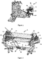
Figure 1 shows a first side view of a binding material storage apparatus in accordance with the present invention located on a baler frame; -
Figure 2 shows a first perspective view of the binding material storage apparatus ofFigure 1 ; -
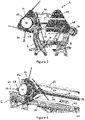
Figure 3 shows a second perspective view of the binding material storage apparatus ofFigure 1 ; -
Figure 4 shows a first perspective view of first end of the binding material storage apparatus ofFigure 1 ; -
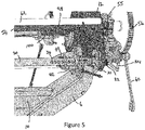
Figure 5 shows a second perspective view of the first end of the binding material storage apparatus shown inFigure 1 ; -
Figure 6 shows a third perspective view of the first end of the binding material storage apparatus shown inFigure 1 ; -
Figure 7 shows a perspective view of an adjustable locating element suitable for use in the present invention; -
Figure 8 shows a first perspective view of a second end of the binding material storage apparatus shown inFigure 1 ; -
Figure 9 shows a second perspective view of the second end of the binding material storage apparatus shown inFigure 1 ; and -
Figure 10 shows a schematic view of elements of the invention. - The invention will now be described in the following detailed description with reference to the drawings, wherein preferred embodiments are described in detail to enable practice of the invention. Although the invention is described with reference to these specific preferred embodiments, it will be understood that the invention is not limited to these preferred embodiments. But to the contrary, the invention includes numerous alternatives, modifications and equivalents as will become apparent from consideration of the following detailed description.
- Reference to terms such as longitudinal, transverse and vertical are made with respect to a longitudinal vehicle axis which is parallel to a normal forward direction of travel.
- As is known in the art, binding refers to the binding of a bale within the baling chamber of a round baler and is distinguished from the binding of a bale outside of the baling chamber for example on a wrapping table of a wrapping apparatus.
- With reference to the Figures, a binding
material storage apparatus 2 in accordance with the present invention is shown. The bindingmaterial storage apparatus 2 is provided with a support structure which in turn allows the binding material storage apparatus to be connected to a frame 4 of a baler (Figure 1 ). The support structure comprisesside elements cross beam 10. Lower portions of each of theside elements side elements - In the apparatus of the illustrated embodiment, up to three rolls of binding
material 90 may be stored. - The binding material storage apparatus comprises a magazine located between the
side elements second end plates support elements 20 extend between theend plates support element 20 is pivotally connected at a first end tofirst end plate 12 at a first side of the binding material storage apparatus and releasably connected at a second end to thesecond end plate 14 at the second side of the binding material storage apparatus. Eachsupport element 20 comprises a bar mounted for free rotation at a second end within anend housing 21. Theend housing 21 is adapted to be received within a latching device 24 provided on the inner side of thefirst end plate 12. - A biased
retaining pin 22 is mounted to thefirst side plate 12 of the binding material storage apparatus. A free end of theretaining pin 22 secures the latching device 24 in position on an inner side of thefirst side plate 12. The latching device 24 secures the first end of thesupport element 20 in a working position. By withdrawing the retainingpin 22 against the action of the biasing means, the latching device 24 is released allowing the first end of the supportingelement 20 to be moved away from thefirst side plate 12 of the binding material storage apparatus. In practice, this allows the first end of thesupport element 20 to be angled down towards a suitable bindingmaterial roll support 26 located beneath the binding material storage apparatus. - Towards each end, each
support member 20 is provided with a number of throughbores 32. Where the bar of thesupport element 20 is formed as a tubular member, the though bore conveniently comprises a pair of diametrically aligned through bores (as shown inFigure 5 ). - An adjustable locating
element 34 is provided at each end of eachsupport element 20. The adjustable locatingelement 34 comprises amain body portion 36 with a keyhole opening or channel allowing the adjustable locatingelement 34 to be passed over and be seated on thesupport element 20. Conveniently the inner end of the channel is semi-circular to allow proper seating of the adjustable locatingelement 34 on thesupport element 20. Themain body portion 36 is provided with parallellateral elements 38, each provided with a number of throughbores 40. These throughbores 40 are sized and located to be aligned with thebores 32 in thesupport element 20. Theadjustable locating element 34 further comprises a plurality of circumferentially locatedfins 42. Each of thefins 42 incudes a curved edge arranged to be angled down towards the centre of the binding material storage apparatus when theadjustable locating element 34 is in position on thesupport element 20. - A first end of a clip 28 is pivotally attached to a second end of a
peg 30 and is moveable between a first position in which the clip encircles a portion of a locating element mounted on thesupport element 20 and a second position in which it does not. In use, thepeg 30 extends through both theadjustable locating element 34 and thesupport element 20 to locate theadjustable locating element 34 axially with respect to thesupport element 20. - The second end of the support element is supported at the second side of the binding material storage apparatus by a pivoting joint (
Figure 9 ). A further adjustable locatingelement 34 is fixed in a suitable manner towards the second end of eachsupport element 20. The further adjustable locating element is of similar construction to the first adjustable locatingelement 34 and like reference numerals are used. - The
second end plate 14 is provided with a plurality of openings. Each opening is provided with an inwardly extendingboss 48. For each opening, a central spindle 50 is mounted in a suitable bearing. Agear 52 is mounted to each central spindle on an outer side of thesecond end plate 14. An inner end of each spindle 50 is provided with aclevis 46 for connecting with the second end of the support element by use of a clevis pin. In an alternative embodiment a universal joint may be used to connect thesupport member 20 with the central spindle 50. - The
side element 8 at the second end of the magazine is provided with an electrically controlledbraking gear 70. - The
cross beam 10 is conveniently provided with abiased lever 80. The biased lever comprises first andsecond side arms 82. First ends of the side arms are connected by a connecting rod about which abiasing spring 84 is mounted. Second ends of the side arms are connected by a plurality of connecting pins on which are mountedrollers 86. The connecting pins are provided in an arcuate arrangement at the second end of the biasedlever 80. Conveniently, the position of the lever may be detected by asensor 88. - The
sensor 88 is in electronic communication with anelectronic control unit 110. The electronic control unit has access to amemory unit 112. Thememory unit 112 may take any suitable form and is in electronic communication with theelectronic control unit 110. Thememory unit 112 is adapted to store, in any suitable manner such as a database or look up table, reference values as described below. Theelectronic control unit 110 is also in connection with the electrically controlledbraking gear 70. - Conveniently the signals between the electronic components are provided by way of a suitable data communication network 114 such as one compliant with the ISOBUS standard (a network in conformance to ISO 11783).
- The
electronic control unit 110 may conveniently comprise a single processor located on the baler or its functions may be split between a first processor located on the baler and one or more additional processors located on an agricultural vehicle towing the baler, the additional processor(s) being in electronic communication with the first processor. -
Apparatus 116 to determine the kind of binding material on the roll of binding material may also be provided in electronic communication with theelectronic control unit 110.Such apparatus 116 may comprise a user operated input device by which the operator can indicate the kind of wrapping material present on the roll of wrapping material in the dispense position. The user operated input device may be provided on the baler or in an operator's cab of an agricultural vehicle used to tow the baler. Alternatively, such apparatus may comprise a sensor mounted on the baler to determine the kind of wrapping material present on the roll of wrapping material in the dispense position. - A
central axle 54 extends through thefirst end plate 12 across the bindingmaterial storage apparatus 2 and through thesecond end plate 14. Each end of thecentral axle 54 is mounted in a suitable bearing provided in a mounting 55 provided at an upper end of eachside support - A first end of the magazine is provided with a drive mechanism to enable rotation of the magazine. A first end of the
central axle 54 is provided with alarger gear 56 mounted outside of thefirst side support 6. Thefirst side support 6 is further provided with a suitably located mounting aperture. - In the illustrated embodiment of
Figures 1 to 9 , a manual drive mechanism is provided. A releasable handle or crank 60 is provided with asmaller drive gear 58 mounted at one end about a guide pin or spigot. Convenientlysmaller drive gear 58 is mounted by way of a clutch or ratchet mechanism to allow one-way movement of thesmaller drive gear 58 with respect to the rest of thehandle 60. In order to rotate the magazine, an operator engages the guide pin within the mounting aperture in thefirst side support 6. When the guide pin is correctly located in the mounting aperture, a periphery of thesmaller gear 58 engages with a periphery of the firstlarger gear 56. - The
handle 60 is used by an operator to rotate the secondsmaller drive gear 58, in turn causing rotation of the firstlarger gear 56 and so rotation of the magazine of the bindingmaterial storage apparatus 2. - In an alternative embodiment, not shown, the second smaller drive gear may be mounted directly to the
first side support 6 and is provided with a powered drive means to be actuated by an operator by way of the electronic control means 110. - The drive means allows an operator to rotate the magazine of the binding material storage apparatus around an axis of rotation to enable selection of preferred roll of binding material 90 - for example either to select a different binding material or to replenish an expired roll without the need to retrieve a roll of binding material for loading. Rotation of the magazine also causes the
gears 52 on the second end to be rotated such that aninitial gear 52 is disengaged from the electrically controlledbraking gear 70 and the electrically controlledbraking gear 70 then becomes engaged with asubsequent gear 52. -
Guide elements 62 are arranged between thesupport elements 20. Eachguide element 62 extends across the bindingmaterial storage apparatus 2 between the first andsecond end plates - In the illustrated embodiment there are three
support elements 20 arranged substantially equidistantly from one another, and threeguide elements 62, eachguide element 62 being located between adjacent pairs ofsupport elements 20. In this embodiment theend plates support elements 20 arranged between the apexes of theend plates - In practice, in order to load a roll of binding material, the first adjustable locating
element 34 is removed from thesupport element 20 and the biased retainingpin 22 used to release the latching device 24 to allow the second end of thesupport element 20 to be released from thesecond side plate 14 of the binding material storage apparatus and allowed to incline at an angle. - Any empty rolls of binding material may then be removed from the
support element 20. -
Rolls 90 of binding material typically comprise a central tube around which has been wound a length of binding material. When thesupport element 20 is released in this way, the second end of thesupport element 20 is angled such that loading of the roll of binding material onto the bindingmaterial support 26 centres the second end of thesupport element 20 within a tube of a roll of binding material to be loaded. A fresh roll of binding material is then pushed into position along thesupport element 20 such that a first end of the tube of the roll of binding material engages with thefins 42 of the second adjustable locatingelement 46 thereby centring the first end of the roll of binding material on thesupport element 20. - The first adjustable locating
element 34 is then returned to the second end of thesupport element 20 and pushed into the second end of the roll of binding material. Across piece 92 is added to the open end of the channel (cfFigure 7 ). Thecross piece 92 passes over locatingpins 94 provided on themain body portion 36 of the locatingelement 34 and secured in place using aclip 96 at each end of thecross piece 92, theclips 96 passing through a through opening in each respective locatingpin 94. Conveniently theclips 96 are tethered to theadjustable locating element 34, in any suitable manner, so that theclips 96 do not become lost and are readily to hand for use by an operator. - The second end of the support element 20 (together with the roll of binding material) is then raised so that the second end of the support element 20 (more specifically the end housing 21) engages in the latch mechanism 24 and the second end of the
support element 20 is once again supported at the second side of the bindingmaterial storage apparatus 2. - The
central axle 54 is provided toward the second end with a radiallyenlarged region 98. This region is provided with a plurality ofblind bores 100 arranged axially along theenlarged region 98. - A lever (not shown) is engaged at one end in one of the plurality of blind bores 100. The other end of the lever is rotated to engage an
abutment surface 102 forming part of aprotrusion 103 provided on themain body portion 36 of theadjustable locating element 34. Further rotation of the lever is used to drive theadjustable locating element 34 into the central tube of the roll of binding material and to bring thebores 40 in line with thebores 32 of thesupport element 20. Thepin 30 can then be inserted to hold theadjustable locating element 34 in place. Theclasp 33 attached to the end of thepin 30 is then pivoted about theadjustable locating element 34 to hold thepin 30 in position. - The
larger gear 56 is provided with a spring biased lockinghandle 104. The locking handle serves to prevent undesired rotation of the rotary magazine. - The
larger gear 56 is provided with a spring biased lockinghandle 104. The locking handle serves to prevent undesired rotation of the rotary magazine. - In order to load a subsequent roll of binding material, for example a roll of a different binding material, the operator needs to move the biased locking handle from a first position in which movement of the
larger gear 56 and so the magazine is prevented to second position in which the larger gear may be driven. - In the embodiment of
Figures 2 to 9 , an operator then engages the removeable crank 60 is located in position with thefirst side element 6 so that the secondsmaller gear 58 engages thelarger gear 56. The springbiased handle 104 can then be pivoted to the second position to release thelarger gear 56. Rotation of thesmaller gear 58 then causes the rotation of the bindingmaterial storage apparatus 20 about theaxle 54. Once afurther support element 20 is adjacent the bindingmaterial support 26, the springbiased handle 104 is returned to its initial position so that further movement of thelarger gear 56 is prevented. Thehandle 60 is then removed from thesecond side element 6 and returned to a storage location. The process for loading a roll of binding material to asupport element 20 may now be repeated. - Once the binding
material storage apparatus 20 has been loaded with the desired binding material(s), the operator rotates the bindingmaterial storage apparatus 20 until a desired roll of binding material is in position adjacent a binding material feed apparatus. The operator next removes a free end of the appropriate binding material and loops this over anadjacent guide element 62 and then directs the free end of the appropriate binding material into the adjacent binding material feed apparatus. - The second adjustable locating
element 34 provided at the first end of thesupport element 20 may also be axially adjustable to allow for differing widths of rolls of binding material, for example rolls of binding film are typically of greater width than rolls of netwrap. In such a case thepin 30 is removed and the adjustable locating element 44 moved along thesupport element 20 to the desired position and thepin 30 returned. Conveniently theholes 32 in thesupport element 20 are arranged to allow for central positioning on eachsupport element 20 of the most common widths of rolls of binding material. - Once the desired roll(s) of binding material has been added to the binding material storage apparatus, a free end of the binding material is introduced into a suitable binding material feed apparatus. Following formation of a bale in a baling chamber of the baler, the binding material feed apparatus is operated to introduce the free end of the binding material into the baling chamber. The free end of the binding material then becomes caught between the rotating bale and the baling chamber and rotated with the bale within the baling chamber to wrap the formed bale in the baling chamber.
- It is desirable that the binding material should, once being drawn into the baling chamber by the action of the rotating bale, be subject to pre-stretching to improve binding. The
electronic control unit 110 can be used to control the speed of the electrically controlledbraking gear 70 such that the binding material is subject to pre-stretching. - It is further desirable that the binding material should, once being drawn into the baling chamber by the action of the rotating bale, be subject to a constant pre-stretching regardless of the roll diameter. It is also desirable that the pre-stretching of the binding material be different for different phases of the binding process.
- In practice if there is no change in the position of the
lever 80, no binding material is being consumed. As binding material is removed from aroll 90 of binding material the diameter of theroll 90 of binding material decreases. As the diameter of the roll of binding material decreases singles sent from thesensor 88 to theelectronic control unit 10 change. Theelectronic control unit 110 is able to determine by reference to signals from thesensor 88 the diameter of theroll 90 of binding material the speed at which the binding material is being unwound from the roll and the tension of the binding material. By reference to thememory unit 112, theelectronic control unit 110 actuates the electrically controlledbraking gear 70 to control the speed of rotation of the electrically controlledbraking gear 70. Due to engagement of the electrically controlledbraking gear 70 with thegear 52 in the dispense position, control of the electrically controlledbraking gear 70 controls the speed of rotation of thesupport element 20 and theroll 90 of wrapping material secured to thesupport element 20 by the first and secondadjustable elements 34,44 and in this way controls the pre-stretching of the binding material. - It will be understood that the arrangement of the
rollers 86 is selected to ensure that at least one of therollers 86 is in contact with the outer diameter of aroll 90 of wrapping material mounted on theadjacent support element 20. - It is an advantage of the present invention that control of the pre-stretching of the binding material is possible at any time and at any diameter of the roll of binding material being used.
- It is desirable that control of the pre-stretching of the binding material also takes into account the kind of binding material on the roll of binding material. As the
electronic control unit 110 is in electrical communication withapparatus 116 to determine the kind of binding material, theelectronic control unit 110 by reference to thememory unit 112 is able to control the speed of operation of the electrically controlledbraking gear 70 to take account of the nature of the binding material being dispensed. - From reading the present disclosure, other modifications will be apparent to persons skilled in the art. Such modifications may involve other features which are already known in the field of round balers and component parts therefore and which may be used instead of or in addition to features already described herein.
Claims (8)
- . A binding material storage apparatus comprises a rotary magazine for storage of a plurality of rolls of binding material and first and second side elements between which the rotary magazine is supported for rotation about a horizontal axis between a plurality of discrete positions including a dispense position, each discrete position being suitable for storage of a roll of a binding material, the rotary magazine including first and second end plates between which a plurality of support elements extend, one support element for each of the plurality of discrete positions, each of the support elements being mounted for free rotation within the magazine, the binding material storage apparatus further comprising a spindle and a first gear element at each of the plurality of discrete positions and an electrically controlled braking gear supported on the second side element, each spindle being mounted for free rotation within the second end plate of the rotary magazine and connected at a first end to a second end of an associated support element and connected at a second end to the first gear element, wherein the electrically controlled braking gear engages the first gear element in the dispense position.
- A binding material storage apparatus characterised in that the binding material storage apparatus further comprises an electronic control unit in electrical communication with the electrically controlled braking gear.
- A binding material storage apparatus according to claim 2, characterised in that the binding material storage apparatus further comprises a sensor to detect the size of the roll of binding material, the sensor being in electronic communication with the electronic control unit.
- A binding material storage apparatus according to either claim 2 or claim 3, characterised in that the electronic control unit is in electronic communication with apparatus to determine the kind of binding material on the roll of binding material.
- A binding material storage apparatus according to claim 4, characterised in that apparatus to determine the kind of binding material on the roll of binding material is a user input device.
- A binding material storage apparatus according to claim 5, characterised in that the user input device is provided on a baler.
- A binding material storage apparatus according to claim 5, characterised in that the user input device is provided in an operator's cab of an agricultural vehicle.
- A binding material storage apparatus according to claim 4, characterised in that the apparatus to determine the kind of binding material on the roll of binding material comprises a sensor to detect the kind of binding material on the roll of binding material.
Applications Claiming Priority (1)
| Application Number | Priority Date | Filing Date | Title |
|---|---|---|---|
| GBGB2106244.3A GB202106244D0 (en) | 2021-04-30 | 2021-04-30 | Baling apparatus |
Publications (2)
| Publication Number | Publication Date |
|---|---|
| EP4082327A1 true EP4082327A1 (en) | 2022-11-02 |
| EP4082327B1 EP4082327B1 (en) | 2024-12-11 |
Family
ID=76300955
Family Applications (1)
| Application Number | Title | Priority Date | Filing Date |
|---|---|---|---|
| EP22167087.0A Active EP4082327B1 (en) | 2021-04-30 | 2022-04-07 | Binding material storage apparatus for a baling press |
Country Status (3)
| Country | Link |
|---|---|
| US (1) | US11684013B2 (en) |
| EP (1) | EP4082327B1 (en) |
| GB (1) | GB202106244D0 (en) |
Families Citing this family (2)
| Publication number | Priority date | Publication date | Assignee | Title |
|---|---|---|---|---|
| CN120858755A (en) * | 2024-04-30 | 2025-10-31 | 凯斯纽荷兰工业美国有限责任公司 | Bale wrapper assembly management system for agricultural harvester |
| USD1075346S1 (en) * | 2024-11-17 | 2025-05-20 | Inicio Technology & Trading Co., Limited | Paper roll dispenser |
Citations (3)
| Publication number | Priority date | Publication date | Assignee | Title |
|---|---|---|---|---|
| US1995722A (en) * | 1931-09-23 | 1935-03-26 | Goss Printing Press Co Ltd | Web controlling mechanism |
| DE10243295A1 (en) * | 2002-09-18 | 2004-05-19 | Lely Maschinenfabrik Gmbh | Round baler |
| EP2932820A1 (en) * | 2014-04-18 | 2015-10-21 | CNH Industrial Belgium nv | Indexing wrapping system and supporting systems |
Family Cites Families (8)
| Publication number | Priority date | Publication date | Assignee | Title |
|---|---|---|---|---|
| US3204887A (en) * | 1964-02-21 | 1965-09-07 | Gellman Mfg Co | Multi paper roll support for article wrapping machines |
| US3386672A (en) * | 1965-08-16 | 1968-06-04 | Appleton Mach | Web supply |
| US4891930A (en) * | 1988-04-04 | 1990-01-09 | Schaefer Alan W | Apparatus and process for applying a cover, to a round hay bale |
| US4934575A (en) * | 1988-07-29 | 1990-06-19 | Shefqet Mustafa | Multiple roll dispenser |
| JPH0699057B2 (en) * | 1992-07-08 | 1994-12-07 | 株式会社東京機械製作所 | Paper feeder for web-fed rotary press |
| US9320199B2 (en) * | 2011-11-22 | 2016-04-26 | Cnh Industrial America Llc | Multiple rolls net wrap assembly |
| US11066198B2 (en) * | 2012-06-18 | 2021-07-20 | TAB Industries, LLC | Stretch film dispenser for orbital pallet wrappers |
| US10356983B2 (en) * | 2014-04-18 | 2019-07-23 | Cnh Industrial America Llc | Indexing net wrap system |
-
2021
- 2021-04-30 GB GBGB2106244.3A patent/GB202106244D0/en not_active Ceased
-
2022
- 2022-04-07 EP EP22167087.0A patent/EP4082327B1/en active Active
- 2022-04-29 US US17/661,495 patent/US11684013B2/en active Active
Patent Citations (3)
| Publication number | Priority date | Publication date | Assignee | Title |
|---|---|---|---|---|
| US1995722A (en) * | 1931-09-23 | 1935-03-26 | Goss Printing Press Co Ltd | Web controlling mechanism |
| DE10243295A1 (en) * | 2002-09-18 | 2004-05-19 | Lely Maschinenfabrik Gmbh | Round baler |
| EP2932820A1 (en) * | 2014-04-18 | 2015-10-21 | CNH Industrial Belgium nv | Indexing wrapping system and supporting systems |
Also Published As
| Publication number | Publication date |
|---|---|
| US20220346322A1 (en) | 2022-11-03 |
| GB202106244D0 (en) | 2021-06-16 |
| US11684013B2 (en) | 2023-06-27 |
| EP4082327B1 (en) | 2024-12-11 |
Similar Documents
| Publication | Publication Date | Title |
|---|---|---|
| US11684013B2 (en) | Baling apparatus | |
| US7644559B2 (en) | Self-threading sheet wrapper for round baler | |
| US11778950B2 (en) | Baling apparatus | |
| EP3003005B1 (en) | Bale wrapping mechanism | |
| US9125345B2 (en) | Web wrap apparatus | |
| US7716903B2 (en) | Double roll feeder for round baler | |
| US20070157556A1 (en) | Device for wrapping a bale of pasture or the like | |
| EP1115276B1 (en) | A holder for film material in roll form | |
| US4072095A (en) | Twine wrapping mechanism for a roll forming machine | |
| US12520768B2 (en) | Baling apparatus | |
| US12232453B2 (en) | Agricultural baler | |
| CA2146677A1 (en) | Bale accumulator | |
| US11617308B2 (en) | Baling apparatus | |
| US5215006A (en) | Twine clamp for round baler twine wrapping apparatus | |
| EP2933195A1 (en) | Indexing wrapping system and supporting systems | |
| US4437399A (en) | Twine-wrapping mechanism for mechanism for a large round baler | |
| US5950530A (en) | Arrangement and process for the securing of twine ends | |
| US5450787A (en) | Twine clamp for round baler twine wrapping apparatus | |
| US4647243A (en) | Twine wrapping mechanism for a large round baler | |
| EP1772408A1 (en) | Self threading sheet wrapper for round baler | |
| CN120787118A (en) | Strapping material tensioning device | |
| US20020175031A1 (en) | Twine brake for large round baler | |
| US3040652A (en) | Wire splicer | |
| NZ286067A (en) | Round hay bale handling equipment rotates and lowers bale onto one end for storage |
Legal Events
| Date | Code | Title | Description |
|---|---|---|---|
| PUAI | Public reference made under article 153(3) epc to a published international application that has entered the european phase |
Free format text: ORIGINAL CODE: 0009012 |
|
| STAA | Information on the status of an ep patent application or granted ep patent |
Free format text: STATUS: THE APPLICATION HAS BEEN PUBLISHED |
|
| AK | Designated contracting states |
Kind code of ref document: A1 Designated state(s): AL AT BE BG CH CY CZ DE DK EE ES FI FR GB GR HR HU IE IS IT LI LT LU LV MC MK MT NL NO PL PT RO RS SE SI SK SM TR |
|
| STAA | Information on the status of an ep patent application or granted ep patent |
Free format text: STATUS: REQUEST FOR EXAMINATION WAS MADE |
|
| 17P | Request for examination filed |
Effective date: 20230502 |
|
| RBV | Designated contracting states (corrected) |
Designated state(s): AL AT BE BG CH CY CZ DE DK EE ES FI FR GB GR HR HU IE IS IT LI LT LU LV MC MK MT NL NO PL PT RO RS SE SI SK SM TR |
|
| P01 | Opt-out of the competence of the unified patent court (upc) registered |
Effective date: 20230518 |
|
| GRAP | Despatch of communication of intention to grant a patent |
Free format text: ORIGINAL CODE: EPIDOSNIGR1 |
|
| STAA | Information on the status of an ep patent application or granted ep patent |
Free format text: STATUS: GRANT OF PATENT IS INTENDED |
|
| GRAS | Grant fee paid |
Free format text: ORIGINAL CODE: EPIDOSNIGR3 |
|
| GRAA | (expected) grant |
Free format text: ORIGINAL CODE: 0009210 |
|
| STAA | Information on the status of an ep patent application or granted ep patent |
Free format text: STATUS: THE PATENT HAS BEEN GRANTED |
|
| RIC1 | Information provided on ipc code assigned before grant |
Ipc: B65H 16/00 20060101ALI20241010BHEP Ipc: A01F 15/07 20060101AFI20241010BHEP |
|
| INTG | Intention to grant announced |
Effective date: 20241018 |
|
| AK | Designated contracting states |
Kind code of ref document: B1 Designated state(s): AL AT BE BG CH CY CZ DE DK EE ES FI FR GB GR HR HU IE IS IT LI LT LU LV MC MK MT NL NO PL PT RO RS SE SI SK SM TR |
|
| REG | Reference to a national code |
Ref country code: GB Ref legal event code: FG4D |
|
| REG | Reference to a national code |
Ref country code: CH Ref legal event code: EP |
|
| REG | Reference to a national code |
Ref country code: IE Ref legal event code: FG4D |
|
| REG | Reference to a national code |
Ref country code: DE Ref legal event code: R096 Ref document number: 602022008531 Country of ref document: DE |
|
| REG | Reference to a national code |
Ref country code: LT Ref legal event code: MG9D |
|
| PG25 | Lapsed in a contracting state [announced via postgrant information from national office to epo] |
Ref country code: HR Free format text: LAPSE BECAUSE OF FAILURE TO SUBMIT A TRANSLATION OF THE DESCRIPTION OR TO PAY THE FEE WITHIN THE PRESCRIBED TIME-LIMIT Effective date: 20241211 |
|
| PG25 | Lapsed in a contracting state [announced via postgrant information from national office to epo] |
Ref country code: FI Free format text: LAPSE BECAUSE OF FAILURE TO SUBMIT A TRANSLATION OF THE DESCRIPTION OR TO PAY THE FEE WITHIN THE PRESCRIBED TIME-LIMIT Effective date: 20241211 |
|
| PG25 | Lapsed in a contracting state [announced via postgrant information from national office to epo] |
Ref country code: BG Free format text: LAPSE BECAUSE OF FAILURE TO SUBMIT A TRANSLATION OF THE DESCRIPTION OR TO PAY THE FEE WITHIN THE PRESCRIBED TIME-LIMIT Effective date: 20241211 |
|
| REG | Reference to a national code |
Ref country code: NL Ref legal event code: MP Effective date: 20241211 |
|
| PG25 | Lapsed in a contracting state [announced via postgrant information from national office to epo] |
Ref country code: ES Free format text: LAPSE BECAUSE OF FAILURE TO SUBMIT A TRANSLATION OF THE DESCRIPTION OR TO PAY THE FEE WITHIN THE PRESCRIBED TIME-LIMIT Effective date: 20241211 |
|
| PG25 | Lapsed in a contracting state [announced via postgrant information from national office to epo] |
Ref country code: NO Free format text: LAPSE BECAUSE OF FAILURE TO SUBMIT A TRANSLATION OF THE DESCRIPTION OR TO PAY THE FEE WITHIN THE PRESCRIBED TIME-LIMIT Effective date: 20250311 |
|
| PG25 | Lapsed in a contracting state [announced via postgrant information from national office to epo] |
Ref country code: LV Free format text: LAPSE BECAUSE OF FAILURE TO SUBMIT A TRANSLATION OF THE DESCRIPTION OR TO PAY THE FEE WITHIN THE PRESCRIBED TIME-LIMIT Effective date: 20241211 Ref country code: GR Free format text: LAPSE BECAUSE OF FAILURE TO SUBMIT A TRANSLATION OF THE DESCRIPTION OR TO PAY THE FEE WITHIN THE PRESCRIBED TIME-LIMIT Effective date: 20250312 |
|
| PG25 | Lapsed in a contracting state [announced via postgrant information from national office to epo] |
Ref country code: RS Free format text: LAPSE BECAUSE OF FAILURE TO SUBMIT A TRANSLATION OF THE DESCRIPTION OR TO PAY THE FEE WITHIN THE PRESCRIBED TIME-LIMIT Effective date: 20250311 |
|
| PG25 | Lapsed in a contracting state [announced via postgrant information from national office to epo] |
Ref country code: NL Free format text: LAPSE BECAUSE OF FAILURE TO SUBMIT A TRANSLATION OF THE DESCRIPTION OR TO PAY THE FEE WITHIN THE PRESCRIBED TIME-LIMIT Effective date: 20241211 |
|
| REG | Reference to a national code |
Ref country code: AT Ref legal event code: MK05 Ref document number: 1749560 Country of ref document: AT Kind code of ref document: T Effective date: 20241211 |
|
| PG25 | Lapsed in a contracting state [announced via postgrant information from national office to epo] |
Ref country code: SM Free format text: LAPSE BECAUSE OF FAILURE TO SUBMIT A TRANSLATION OF THE DESCRIPTION OR TO PAY THE FEE WITHIN THE PRESCRIBED TIME-LIMIT Effective date: 20241211 |
|
| PG25 | Lapsed in a contracting state [announced via postgrant information from national office to epo] |
Ref country code: PL Free format text: LAPSE BECAUSE OF FAILURE TO SUBMIT A TRANSLATION OF THE DESCRIPTION OR TO PAY THE FEE WITHIN THE PRESCRIBED TIME-LIMIT Effective date: 20241211 |
|
| PGFP | Annual fee paid to national office [announced via postgrant information from national office to epo] |
Ref country code: DE Payment date: 20250422 Year of fee payment: 4 |
|
| PG25 | Lapsed in a contracting state [announced via postgrant information from national office to epo] |
Ref country code: IS Free format text: LAPSE BECAUSE OF FAILURE TO SUBMIT A TRANSLATION OF THE DESCRIPTION OR TO PAY THE FEE WITHIN THE PRESCRIBED TIME-LIMIT Effective date: 20250411 |
|
| PGFP | Annual fee paid to national office [announced via postgrant information from national office to epo] |
Ref country code: IT Payment date: 20250430 Year of fee payment: 4 Ref country code: BE Payment date: 20250418 Year of fee payment: 4 |
|
| PG25 | Lapsed in a contracting state [announced via postgrant information from national office to epo] |
Ref country code: PT Free format text: LAPSE BECAUSE OF FAILURE TO SUBMIT A TRANSLATION OF THE DESCRIPTION OR TO PAY THE FEE WITHIN THE PRESCRIBED TIME-LIMIT Effective date: 20250411 |
|
| PG25 | Lapsed in a contracting state [announced via postgrant information from national office to epo] |
Ref country code: EE Free format text: LAPSE BECAUSE OF FAILURE TO SUBMIT A TRANSLATION OF THE DESCRIPTION OR TO PAY THE FEE WITHIN THE PRESCRIBED TIME-LIMIT Effective date: 20241211 |
|
| PGFP | Annual fee paid to national office [announced via postgrant information from national office to epo] |
Ref country code: FR Payment date: 20250425 Year of fee payment: 4 |
|
| PG25 | Lapsed in a contracting state [announced via postgrant information from national office to epo] |
Ref country code: AT Free format text: LAPSE BECAUSE OF FAILURE TO SUBMIT A TRANSLATION OF THE DESCRIPTION OR TO PAY THE FEE WITHIN THE PRESCRIBED TIME-LIMIT Effective date: 20241211 Ref country code: RO Free format text: LAPSE BECAUSE OF FAILURE TO SUBMIT A TRANSLATION OF THE DESCRIPTION OR TO PAY THE FEE WITHIN THE PRESCRIBED TIME-LIMIT Effective date: 20241211 |
|
| PG25 | Lapsed in a contracting state [announced via postgrant information from national office to epo] |
Ref country code: SK Free format text: LAPSE BECAUSE OF FAILURE TO SUBMIT A TRANSLATION OF THE DESCRIPTION OR TO PAY THE FEE WITHIN THE PRESCRIBED TIME-LIMIT Effective date: 20241211 |
|
| PG25 | Lapsed in a contracting state [announced via postgrant information from national office to epo] |
Ref country code: CZ Free format text: LAPSE BECAUSE OF FAILURE TO SUBMIT A TRANSLATION OF THE DESCRIPTION OR TO PAY THE FEE WITHIN THE PRESCRIBED TIME-LIMIT Effective date: 20241211 |
|
| PGFP | Annual fee paid to national office [announced via postgrant information from national office to epo] |
Ref country code: IE Payment date: 20250422 Year of fee payment: 4 |
|
| PG25 | Lapsed in a contracting state [announced via postgrant information from national office to epo] |
Ref country code: SE Free format text: LAPSE BECAUSE OF FAILURE TO SUBMIT A TRANSLATION OF THE DESCRIPTION OR TO PAY THE FEE WITHIN THE PRESCRIBED TIME-LIMIT Effective date: 20241211 |
|
| REG | Reference to a national code |
Ref country code: DE Ref legal event code: R097 Ref document number: 602022008531 Country of ref document: DE |
|
| PG25 | Lapsed in a contracting state [announced via postgrant information from national office to epo] |
Ref country code: DK Free format text: LAPSE BECAUSE OF FAILURE TO SUBMIT A TRANSLATION OF THE DESCRIPTION OR TO PAY THE FEE WITHIN THE PRESCRIBED TIME-LIMIT Effective date: 20241211 |
|
| PLBE | No opposition filed within time limit |
Free format text: ORIGINAL CODE: 0009261 |
|
| STAA | Information on the status of an ep patent application or granted ep patent |
Free format text: STATUS: NO OPPOSITION FILED WITHIN TIME LIMIT |
|
| REG | Reference to a national code |
Ref country code: CH Ref legal event code: L10 Free format text: ST27 STATUS EVENT CODE: U-0-0-L10-L00 (AS PROVIDED BY THE NATIONAL OFFICE) Effective date: 20251022 |
|
| 26N | No opposition filed |
Effective date: 20250912 |
|
| REG | Reference to a national code |
Ref country code: CH Ref legal event code: H13 Free format text: ST27 STATUS EVENT CODE: U-0-0-H10-H13 (AS PROVIDED BY THE NATIONAL OFFICE) Effective date: 20251125 |
|
| PG25 | Lapsed in a contracting state [announced via postgrant information from national office to epo] |
Ref country code: LU Free format text: LAPSE BECAUSE OF NON-PAYMENT OF DUE FEES Effective date: 20250407 |
|
| PG25 | Lapsed in a contracting state [announced via postgrant information from national office to epo] |
Ref country code: MC Free format text: LAPSE BECAUSE OF FAILURE TO SUBMIT A TRANSLATION OF THE DESCRIPTION OR TO PAY THE FEE WITHIN THE PRESCRIBED TIME-LIMIT Effective date: 20241211 |
|
| PG25 | Lapsed in a contracting state [announced via postgrant information from national office to epo] |
Ref country code: CH Free format text: LAPSE BECAUSE OF NON-PAYMENT OF DUE FEES Effective date: 20250430 |