EP4081413B1 - Improved acoustic foam profile for pneumatic tires - Google Patents
Improved acoustic foam profile for pneumatic tires Download PDFInfo
- Publication number
- EP4081413B1 EP4081413B1 EP19845663.4A EP19845663A EP4081413B1 EP 4081413 B1 EP4081413 B1 EP 4081413B1 EP 19845663 A EP19845663 A EP 19845663A EP 4081413 B1 EP4081413 B1 EP 4081413B1
- Authority
- EP
- European Patent Office
- Prior art keywords
- tire
- foam
- self
- grooves
- circumferential
- Prior art date
- Legal status (The legal status is an assumption and is not a legal conclusion. Google has not performed a legal analysis and makes no representation as to the accuracy of the status listed.)
- Active
Links
Images

Classifications
-
- B—PERFORMING OPERATIONS; TRANSPORTING
- B60—VEHICLES IN GENERAL
- B60C—VEHICLE TYRES; TYRE INFLATION; TYRE CHANGING; CONNECTING VALVES TO INFLATABLE ELASTIC BODIES IN GENERAL; DEVICES OR ARRANGEMENTS RELATED TO TYRES
- B60C19/00—Tyre parts or constructions not otherwise provided for
- B60C19/002—Noise damping elements provided in the tyre structure or attached thereto, e.g. in the tyre interior
-
- B—PERFORMING OPERATIONS; TRANSPORTING
- B60—VEHICLES IN GENERAL
- B60C—VEHICLE TYRES; TYRE INFLATION; TYRE CHANGING; CONNECTING VALVES TO INFLATABLE ELASTIC BODIES IN GENERAL; DEVICES OR ARRANGEMENTS RELATED TO TYRES
- B60C19/00—Tyre parts or constructions not otherwise provided for
- B60C19/12—Puncture preventing arrangements
- B60C19/122—Puncture preventing arrangements disposed inside of the inner liner
Definitions
- the subject matter of the present invention relates to tires, and more specifically to tires having on their radially inner surface a layer of a sealant intended to seal a puncture in the crown of the tire and a strip of foam intended to damp the cavity noise.
- the present invention relates to a tire according to the preamble of claim 1, such as it is e.g. known from DE 10 2014 206 009 A1 .
- the pneumatic tire still is subject to punctures and air loss as a result of those punctures.
- tire manufactures may apply a self-sealing product upon the radially inner surface of the inner-liner of the tire.
- the sealant because of the product's softness and ability to creep readily, penetrates the puncture and prevents the pneumatic tire from losing air.
- Such a tire with a layer able to creep and seal the puncture is said to be a "self-sealing tire.”
- the grooves of the tire being the thinnest portion of the tire's tread are particularly susceptible to penetration damage.
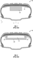
- the acoustic foam 100 when applied on the self-sealing layer 50, such as the cross section of the tire 10 shown in FIG. 1 , reduces the effectiveness of the self-sealing abilities of the tire 10, resulting in a need for additional self-sealing product and/or acceptance of a reduction of the self-sealing performance.
- the additional self-sealing product needed for improved effectiveness is both expensive and adds unnecessary additional weight to the tire.
- FIG. 2 One such attempt, as shown in FIG. 2 , is where the radially outer surface of acoustic foam 100 is cut to form a U-shape profile.
- the acoustic foam 100 touches and secures itself to the self-sealing layer 50 at the lateral ends 102, 104 of the acoustic foam 100, leaving the middle portion radially inward from the self-sealing layer.
- FIG. 3 it is difficult to achieve such careful positioning, and even when achieved, inadvertent compression of the acoustic foam 100 results, as shown in FIG. 3 , in the middle portion adhering to the self-sealing layer, resulting in decreased self-sealing performance and tire imbalance.
- An acoustic foam profile which does not appreciably interfere with the effectiveness of the self-sealing layer is desirous.
- a foam profile which does not interfere with the effectiveness of the self-sealing layer and prevents the acoustic foam structure from collapsing into the self-sealing layer would be particularly advantageous.
- a polyalphaolefin adhesive sealant is applied to the radial interior of the tire in the region of the belt reinforcements of the crown.
- a noise-dampening foam ring having circumferential grooves in the radial outside surface of the foam is applied to the adhesive sealant.
- the grooves of the foam are laterally aligned with the circumferential grooves of the tire such that the foam touches the sealant on areas that are not laterally aligned with the longitudinal grooves of the tire. This prevents the foam from hindering the flow of sealant in the area immediately below the tread grooves improving the self-sealing performance of the tire.
- the present invention provides a pneumatic tire having a layer of self-sealing product applied to the interior of the pneumatic tire in the crown region with a layer of acoustic foam applied to the surface of the self-sealing product.
- Axial direction or the letter “A” in the figures refers to a direction parallel to the axis of rotation of for example, the tire, and/or wheel as it travels along a road surface.
- Ring direction or the letter “R” in the figures refers to a direction that is orthogonal to the axial direction and extends in the same direction as any radius that extends orthogonally from the axial direction.
- Equatorial plane means a plane that passes perpendicular to the axis of rotation and bisects the outer tread band and/or wheel structure.
- Crossing direction or the letter “C” in the figures refers to a direction is orthogonal to the axial direction and orthogonal to a radial direction.
- Ring plane means a plane that passes perpendicular to the equatorial plane and through the axis of rotation of the wheel.
- “Lateral direction” or the letter “L” means a direction that is orthogonal to an equatorial plane.
- FIG. 4 provides an exemplary embodiment of a tire 10 having a tread surface 12 having a plurality of circumferential tread grooves 16 on the tread surface 12.
- the inner surface 14 of the tire 10 faces an internal cavity 20 which is made when the tire is mounted upon a rim 40.
- a self-sealing adhesive layer 50 is positioned on the inner surface 14 of the tire.
- the adhesive layer 50 is positioned circumferentially around the interior surface 14 of the tire 10 and is laterally aligned with the belt reinforcement layers 18 of the tire.
- the self-sealing adhesive layer 50 in this embodiment is a gel of polyurethane. Other materials may be used, including a sealant of polyalphaolefin
- a strip of noise dampening foam 100 is attached on the radially inner surface of the self-sealing adhesive layer 50.
- the noise dampening foam 100 has a plurality of circumferential grooves 120, 130. Each of the circumferential grooves 120, 130 face the interior surface 14 of the tire 10.
- support walls 110 forming the lateral sides of the circumferential grooves 120, 130 of the noise dampening foam 100 contact the self-sealing adhesive layer 50 securing the noise dampening foam 100 to the interior of the tire 10.
- the support walls 110 help keep the bottom surfaces of the circumferential grooves 120, 130 from making contact with the adhesive layer during installation and during the tire's operation.
- the support walls 110 make contact with the self-sealing adhesive 50 in the region laterally between the circumferential tread grooves 16 of the tire 10.
- each of the circumferential grooves 120, 130 of the noise dampening foam are positioned in lateral alignment with one of the plurality of circumferential tread grooves 16.
- each circumferential tread groove 16 does not have foam contacting the self-sealing adhesive layer that lies below it. If the tire is pierced by a foreign object within the tread groove 16, the self-sealing adhesive material 50 is able to flow unrestricted by the foam 100 to fill the puncture caused by the foreign object.
- the noise dampening foam may be in the form of a strip having two ends. The two ends may be bonded together. The two ends of the noise dampening foam may be butted against one another or alternatively may be separated by a gap.
- the noise dampening foam strip may be in the form of a continuous ring.
- each of the grooves 120, 130 of the noise dampening foam 100 are wider than the width of the tire tread groove 16 of which it is laterally aligned with.
- the grooves of the noise dampening ring are 15.5 mm wide in the lateral direction and 10 mm deep in the radial direction while the tread grooves are 5 mm wide as measured at the bottom of the tread groove 16 and approximately 10 mm wide at the radial outer surface of the tread 12.
Landscapes
- Engineering & Computer Science (AREA)
- Mechanical Engineering (AREA)
- Tires In General (AREA)
Description
- The subject matter of the present invention relates to tires, and more specifically to tires having on their radially inner surface a layer of a sealant intended to seal a puncture in the crown of the tire and a strip of foam intended to damp the cavity noise. In particular, the present invention relates to a tire according to the preamble of claim 1, such as it is e.g. known from
DE 10 2014 206 009 A1 . - The development of motor vehicle technology has lead to a demand for the reduction of noise perceived by the occupants of the vehicle. In particular, electrical propulsion has reduced compartment noise levels such that the noise of the tires, and in particular the noise associated with the internal cavity of the tire while rolling, has become noticeable. Attaching foam strips to the internal surface of the pneumatic tire have proved to be a successful method to dampen the audible tire cavity, for example,
US Pat. No. 7,975,740 . - The pneumatic tire still is subject to punctures and air loss as a result of those punctures. To mitigate or eliminate the air loss due to puncture, tire manufactures may apply a self-sealing product upon the radially inner surface of the inner-liner of the tire. When a nail, or other object, penetrates the tire crown, the sealant, because of the product's softness and ability to creep readily, penetrates the puncture and prevents the pneumatic tire from losing air. Such a tire with a layer able to creep and seal the puncture is said to be a "self-sealing tire." The grooves of the tire being the thinnest portion of the tire's tread are particularly susceptible to penetration damage.
- With the advent of electric vehicles, it has become desirous to combine these technologies, such as shown in U.S. Pat. App. Pub. No.
US 2016/0347127 . Combining the technologies, however, have been met with certain difficulties. In particular, theacoustic foam 100, when applied on the self-sealing layer 50, such as the cross section of thetire 10 shown inFIG. 1 , reduces the effectiveness of the self-sealing abilities of thetire 10, resulting in a need for additional self-sealing product and/or acceptance of a reduction of the self-sealing performance. The additional self-sealing product needed for improved effectiveness is both expensive and adds unnecessary additional weight to the tire. - Attempts to increase the effectiveness of the self-sealing layer have been made. One such attempt, as shown in
FIG. 2 , is where the radially outer surface ofacoustic foam 100 is cut to form a U-shape profile. When installed, theacoustic foam 100 touches and secures itself to the self-sealinglayer 50 at thelateral ends acoustic foam 100, leaving the middle portion radially inward from the self-sealing layer. In practice, however, it is difficult to achieve such careful positioning, and even when achieved, inadvertent compression of theacoustic foam 100 results, as shown inFIG. 3 , in the middle portion adhering to the self-sealing layer, resulting in decreased self-sealing performance and tire imbalance. - An acoustic foam profile which does not appreciably interfere with the effectiveness of the self-sealing layer is desirous. In particular a foam profile which does not interfere with the effectiveness of the self-sealing layer and prevents the acoustic foam structure from collapsing into the self-sealing layer would be particularly advantageous.
- This problem is solved by a tire according to claim 1. The dependent claims relate to advantageous embodiments.
- Aspects and advantages of the invention will be set forth in part in the following description.
- In one embodiment, a polyalphaolefin adhesive sealant is applied to the radial interior of the tire in the region of the belt reinforcements of the crown. A noise-dampening foam ring having circumferential grooves in the radial outside surface of the foam is applied to the adhesive sealant. The grooves of the foam are laterally aligned with the circumferential grooves of the tire such that the foam touches the sealant on areas that are not laterally aligned with the longitudinal grooves of the tire. This prevents the foam from hindering the flow of sealant in the area immediately below the tread grooves improving the self-sealing performance of the tire.
- These and other features, aspects and advantages of the present invention will become better understood with reference to the following description and appended claims. The accompanying drawings, which are incorporated in and constitute a part of this specification, illustrate embodiments of the invention and, together with the description, serve to explain the principles of the invention.
- A full and enabling disclosure of the present invention, including the best mode thereof, directed to one of ordinary skill in the art, is set forth in the specification, which makes reference to the appended figures, in which:
-
FIG. 1 provides a cross-section view of a prior art tire having acoustic foam and a self-sealing product layer applied to the interior taken through the axis of rotation of the tire. -
FIG. 2 provides a cross-section view of a prior art tire having U-shaped acoustic foam and a sealant layer applied to the interior. -
FIG. 3 provides a cross-section view of a prior art tire having U-shaped acoustic foam and a sealant layer applied to the interior with the U-shaped acoustic foam collapsed into the sealant layer. -
FIG. 4 provides a cross-section view of an embodiment of the invention, having acoustic foam and a sealant layer applied to the interior of a pneumatic tire. - The use of identical or similar reference numerals in different figures denotes identical or similar features.
- The present invention provides a pneumatic tire having a layer of self-sealing product applied to the interior of the pneumatic tire in the crown region with a layer of acoustic foam applied to the surface of the self-sealing product. For purposes of describing the invention, reference now will be made in detail to embodiments and/or methods of the invention, one or more examples of which are illustrated in or with the drawings. Each example is provided by way of explanation of the invention, not limitation of the invention. In fact, it will be apparent to those skilled in the art that various modifications and variations can be made in the present invention without departing from the scope of the invention defined in the appended claims. For instance, features or steps illustrated or described as part of one embodiment, can be used with another embodiment or steps to yield a still further embodiments or methods. Thus, it is intended that the present invention covers such modifications and variations as come within the scope of the appended claims.
- The following terms are defined as follows for this disclosure:
- "Axial direction" or the letter "A" in the figures refers to a direction parallel to the axis of rotation of for example, the tire, and/or wheel as it travels along a road surface.
- "Radial direction" or the letter "R" in the figures refers to a direction that is orthogonal to the axial direction and extends in the same direction as any radius that extends orthogonally from the axial direction.
- "Equatorial plane" means a plane that passes perpendicular to the axis of rotation and bisects the outer tread band and/or wheel structure.
- "Circumferential direction" or the letter "C" in the figures refers to a direction is orthogonal to the axial direction and orthogonal to a radial direction.
- "Radial plane" means a plane that passes perpendicular to the equatorial plane and through the axis of rotation of the wheel.
- "Lateral direction" or the letter "L" means a direction that is orthogonal to an equatorial plane.
-
FIG. 4 provides an exemplary embodiment of atire 10 having atread surface 12 having a plurality ofcircumferential tread grooves 16 on thetread surface 12. Theinner surface 14 of thetire 10 faces aninternal cavity 20 which is made when the tire is mounted upon a rim 40. A self-sealingadhesive layer 50 is positioned on theinner surface 14 of the tire. Theadhesive layer 50 is positioned circumferentially around theinterior surface 14 of thetire 10 and is laterally aligned with thebelt reinforcement layers 18 of the tire. The self-sealingadhesive layer 50 in this embodiment is a gel of polyurethane. Other materials may be used, including a sealant of polyalphaolefin - A strip of
noise dampening foam 100 is attached on the radially inner surface of the self-sealingadhesive layer 50. Thenoise dampening foam 100 has a plurality ofcircumferential grooves circumferential grooves interior surface 14 of thetire 10. In this embodiment,support walls 110 forming the lateral sides of thecircumferential grooves noise dampening foam 100 contact the self-sealingadhesive layer 50 securing thenoise dampening foam 100 to the interior of thetire 10. Thesupport walls 110 help keep the bottom surfaces of thecircumferential grooves support walls 110 make contact with the self-sealingadhesive 50 in the region laterally between thecircumferential tread grooves 16 of thetire 10. - Each of the
circumferential grooves circumferential tread grooves 16. In other words, in the present embodiments, eachcircumferential tread groove 16 does not have foam contacting the self-sealing adhesive layer that lies below it. If the tire is pierced by a foreign object within thetread groove 16, the self-sealingadhesive material 50 is able to flow unrestricted by thefoam 100 to fill the puncture caused by the foreign object. - In this embodiment, only two
circumferential grooves longitudinal tread grooves 16 that thenoise dampening foam 100 laterally spans. In this embodiment, the noise dampening foam laterally spans only twogrooves 16 thus it only contains twogrooves foam 100. - The noise dampening foam may be in the form of a strip having two ends. The two ends may be bonded together. The two ends of the noise dampening foam may be butted against one another or alternatively may be separated by a gap. The noise dampening foam strip may be in the form of a continuous ring.
- The lateral width of each of the
grooves noise dampening foam 100 are wider than the width of thetire tread groove 16 of which it is laterally aligned with. In the embodiment shown, the grooves of the noise dampening ring are 15.5 mm wide in the lateral direction and 10 mm deep in the radial direction while the tread grooves are 5 mm wide as measured at the bottom of thetread groove 16 and approximately 10 mm wide at the radial outer surface of thetread 12. - It should be noted that each of the exemplary embodiments presented and discussed herein should not insinuate limitations of the present subject matter.
- The dimensions and values disclosed herein are not to be understood as being strictly limited to the exact numerical values recited. Instead, unless otherwise specified, each such dimension is intended to mean both the recited value and a functionally equivalent range surrounding that value. For example, a dimension disclosed as "40 mm" is intended to mean "about 40 mm." Also, the dimensions and values disclosed herein are not limited to a specified unit of measurement. For example, dimensions expressed in English units are understood to include equivalent dimensions in metric and other units (e.g., a dimension disclosed as "1 inch" is intended to mean an equivalent dimension of "2.5 cm"). When the term "approximately" is used, it should be understood to include dimensions that are 25% larger or 25% smaller than the value stated.
- The terms "a," "an," and the singular forms of words shall be taken to include the plural form of the same words, such that the terms mean that one or more of something is provided. The terms "at least one" and "one or more" are used interchangeably. Ranges that are described as being "between a and b" are inclusive of the values for "a" and "b."
Claims (8)
- A tire (10) comprisinga tread surface (12),a plurality of circumferential tread grooves (16) on the tread surface (12), an internal cavity (20) and an inner surface (14) facing the internal cavity,a self-sealing adhesive layer (50) positioned on the inner surface (14) of the tire (10); anda strip of noise dampening foam (100) attached to the self-sealing adhesive layer (50), characterised in thatthe strip of noise dampening foam (100) has a plurality of circumferential grooves (120, 130), each of the circumferential grooves (120, 130) of the foam (100) facing the self-sealing adhesive layer (50), each of the circumferential grooves (120, 130) of the foam (100) is positioned in lateral alignment with one of the plurality of circumferential tread grooves (16) to which it corresponds, such that each circumferential tread groove (16) does not have foam contacting the self-sealing adhesive layer (50) that lies below it.
- The tire (10) of claim 1 wherein foam (100) touches the self-sealing adhesive layer (50) at a lateral location between each of the plurality of circumferential tread grooves (16) that the noise dampening foam (100) laterally spans.
- The tire (10) of any of the above claims wherein the noise dampening foam (100) strip is a continuous ring.
- The tire (10) of any of the above claims wherein each of the plurality of circumferential grooves (120, 130) of the noise dampening foam (100) strip has a radial depth of approximately 1 cm.
- The tire (10) of any of the above claims wherein each of the plurality of circumferential tread grooves (16) has a lateral width and wherein each of the plurality of circumferential grooves (120, 130) of the noise dampening foam (100) strip has a lateral width, the lateral width of each of the plurality of circumferential grooves (120, 130) of the noise dampening foam (100) strip being greater than the lateral width of the corresponding circumferential tread grooves (16) of the plurality of circumferential grooves (120, 130).
- The tire (10) of any of the above claims wherein the self-sealing adhesive layer (50) is a polyurethane.
- The tire (10) of any of the claims 1-5, wherein the self-sealing adhesive layer (50) is a polyalphaolefin.
- The tire (10) of any of the above claims wherein noise dampening foam (100) strip is an open cell foam (100).
Applications Claiming Priority (1)
| Application Number | Priority Date | Filing Date | Title |
|---|---|---|---|
| PCT/US2019/068537 WO2021133392A1 (en) | 2019-12-26 | 2019-12-26 | Improved acoustic foam profile for pneumatic tires |
Publications (2)
| Publication Number | Publication Date |
|---|---|
| EP4081413A1 EP4081413A1 (en) | 2022-11-02 |
| EP4081413B1 true EP4081413B1 (en) | 2024-09-11 |
Family
ID=69374383
Family Applications (1)
| Application Number | Title | Priority Date | Filing Date |
|---|---|---|---|
| EP19845663.4A Active EP4081413B1 (en) | 2019-12-26 | 2019-12-26 | Improved acoustic foam profile for pneumatic tires |
Country Status (5)
| Country | Link |
|---|---|
| US (1) | US20230033411A1 (en) |
| EP (1) | EP4081413B1 (en) |
| JP (1) | JP7416957B2 (en) |
| CN (1) | CN114945482B (en) |
| WO (1) | WO2021133392A1 (en) |
Families Citing this family (1)
| Publication number | Priority date | Publication date | Assignee | Title |
|---|---|---|---|---|
| JP7797871B2 (en) * | 2021-12-28 | 2026-01-14 | 住友ゴム工業株式会社 | pneumatic tires |
Family Cites Families (19)
| Publication number | Priority date | Publication date | Assignee | Title |
|---|---|---|---|---|
| JP3988587B2 (en) * | 2002-08-28 | 2007-10-10 | 東海ゴム工業株式会社 | Soundproof tire |
| EP1577123B1 (en) * | 2004-03-16 | 2007-10-17 | Sumitomo Rubber Industries Ltd. | Pneumatic tire with noise damper |
| JP3934621B2 (en) * | 2004-03-16 | 2007-06-20 | 住友ゴム工業株式会社 | Pneumatic tire and rim assembly |
| JP4330550B2 (en) | 2005-04-28 | 2009-09-16 | 住友ゴム工業株式会社 | Pneumatic tire and rim assembly |
| JP5267288B2 (en) * | 2008-05-09 | 2013-08-21 | 横浜ゴム株式会社 | Tire noise reduction device |
| DE102009024454A1 (en) * | 2009-06-10 | 2010-12-16 | Audi Ag | tire |
| WO2012090310A1 (en) * | 2010-12-28 | 2012-07-05 | ソシエテ ド テクノロジー ミシュラン | Pneumatic tire |
| DE102011053686A1 (en) * | 2011-09-16 | 2013-03-21 | Continental Reifen Deutschland Gmbh | Radial type tubeless pneumatic tire for vehicle i.e. passenger car, has vibration damper arranged within circumference of tire on radial inner side of air-permeable inner layer, for damping vibrations along circumference |
| JP5559835B2 (en) * | 2012-05-07 | 2014-07-23 | 住友ゴム工業株式会社 | Pneumatic tire and manufacturing method thereof |
| US20140246133A1 (en) * | 2013-03-04 | 2014-09-04 | E I Du Pont De Nemours And Company | Tire containing a component for reducing vibration-generated noise in a tire and method for reducing tire noise |
| WO2015115486A1 (en) | 2014-01-30 | 2015-08-06 | 住友ゴム工業株式会社 | Sealant tire |
| DE102014206009A1 (en) * | 2014-03-31 | 2015-10-01 | Continental Reifen Deutschland Gmbh | Vehicle tires |
| BR112017028220B1 (en) * | 2015-06-30 | 2021-09-14 | Pirelli Tyre S.P.A. | TIRE FOR VEHICLE WHEELS |
| DE102015212874A1 (en) * | 2015-07-09 | 2017-01-12 | Continental Reifen Deutschland Gmbh | Vehicle tires |
| DE102015221698A1 (en) * | 2015-11-05 | 2017-05-11 | Continental Reifen Deutschland Gmbh | Vehicle tires |
| JP6213623B1 (en) * | 2016-07-14 | 2017-10-18 | 横浜ゴム株式会社 | Pneumatic tire |
| JP6524341B2 (en) * | 2017-01-25 | 2019-06-05 | 住友ゴム工業株式会社 | Pneumatic tire |
| KR102147517B1 (en) * | 2018-12-11 | 2020-08-25 | 한국타이어앤테크놀로지 주식회사 | Tire comprising sealant layer and acoustic absorbent layer |
| JP7238562B2 (en) * | 2019-04-11 | 2023-03-14 | 横浜ゴム株式会社 | pneumatic tire |
-
2019
- 2019-12-26 CN CN201980103458.0A patent/CN114945482B/en active Active
- 2019-12-26 EP EP19845663.4A patent/EP4081413B1/en active Active
- 2019-12-26 JP JP2022539345A patent/JP7416957B2/en active Active
- 2019-12-26 US US17/789,211 patent/US20230033411A1/en not_active Abandoned
- 2019-12-26 WO PCT/US2019/068537 patent/WO2021133392A1/en not_active Ceased
Also Published As
| Publication number | Publication date |
|---|---|
| CN114945482A (en) | 2022-08-26 |
| WO2021133392A1 (en) | 2021-07-01 |
| US20230033411A1 (en) | 2023-02-02 |
| EP4081413A1 (en) | 2022-11-02 |
| JP2023509607A (en) | 2023-03-09 |
| JP7416957B2 (en) | 2024-01-17 |
| CN114945482B (en) | 2023-10-10 |
Similar Documents
| Publication | Publication Date | Title |
|---|---|---|
| EP2067633B1 (en) | Tire noise reduction device and pneumatic tire | |
| KR102089270B1 (en) | Vehicle pneumatic tire | |
| US10723181B2 (en) | Pneumatic tire with specified tread rubber layer thickness and sound-absorbing member width | |
| EP3219515B1 (en) | Pneumatic tire | |
| EP2452838A1 (en) | Puncture sealant laminate and pneumatic tire comprising such a laminate | |
| JPWO2015076382A1 (en) | Pneumatic tire | |
| WO2015076380A1 (en) | Pneumatic tire | |
| US11453253B2 (en) | Pneumatic tire | |
| US11077724B2 (en) | Pneumatic tire | |
| EP4081413B1 (en) | Improved acoustic foam profile for pneumatic tires | |
| US11001105B2 (en) | Pneumatic tire | |
| US20180312013A1 (en) | Pneumatic Tire | |
| US11001100B2 (en) | Pneumatic tire | |
| JP4984614B2 (en) | Pneumatic tire | |
| EP4059738B1 (en) | Run-flat tire | |
| EP3778267B1 (en) | Pneumatic tyre and method for the construction of said pneumatic tyre | |
| US10933700B2 (en) | Pneumatic tire | |
| AU2014341656B2 (en) | Run-flat radial tire | |
| JP7372795B2 (en) | pneumatic tires | |
| KR20230044822A (en) | Pneumatic tire | |
| US11331965B2 (en) | Pneumatic tire | |
| JP2021046128A (en) | Pneumatic tire |
Legal Events
| Date | Code | Title | Description |
|---|---|---|---|
| STAA | Information on the status of an ep patent application or granted ep patent |
Free format text: STATUS: UNKNOWN |
|
| STAA | Information on the status of an ep patent application or granted ep patent |
Free format text: STATUS: THE INTERNATIONAL PUBLICATION HAS BEEN MADE |
|
| PUAI | Public reference made under article 153(3) epc to a published international application that has entered the european phase |
Free format text: ORIGINAL CODE: 0009012 |
|
| STAA | Information on the status of an ep patent application or granted ep patent |
Free format text: STATUS: REQUEST FOR EXAMINATION WAS MADE |
|
| 17P | Request for examination filed |
Effective date: 20220628 |
|
| AK | Designated contracting states |
Kind code of ref document: A1 Designated state(s): AL AT BE BG CH CY CZ DE DK EE ES FI FR GB GR HR HU IE IS IT LI LT LU LV MC MK MT NL NO PL PT RO RS SE SI SK SM TR |
|
| DAV | Request for validation of the european patent (deleted) | ||
| DAX | Request for extension of the european patent (deleted) | ||
| GRAP | Despatch of communication of intention to grant a patent |
Free format text: ORIGINAL CODE: EPIDOSNIGR1 |
|
| STAA | Information on the status of an ep patent application or granted ep patent |
Free format text: STATUS: GRANT OF PATENT IS INTENDED |
|
| INTG | Intention to grant announced |
Effective date: 20240404 |
|
| GRAS | Grant fee paid |
Free format text: ORIGINAL CODE: EPIDOSNIGR3 |
|
| GRAA | (expected) grant |
Free format text: ORIGINAL CODE: 0009210 |
|
| STAA | Information on the status of an ep patent application or granted ep patent |
Free format text: STATUS: THE PATENT HAS BEEN GRANTED |
|
| AK | Designated contracting states |
Kind code of ref document: B1 Designated state(s): AL AT BE BG CH CY CZ DE DK EE ES FI FR GB GR HR HU IE IS IT LI LT LU LV MC MK MT NL NO PL PT RO RS SE SI SK SM TR |
|
| REG | Reference to a national code |
Ref country code: GB Ref legal event code: FG4D |
|
| REG | Reference to a national code |
Ref country code: CH Ref legal event code: EP |
|
| REG | Reference to a national code |
Ref country code: DE Ref legal event code: R096 Ref document number: 602019058856 Country of ref document: DE |
|
| REG | Reference to a national code |
Ref country code: IE Ref legal event code: FG4D |
|
| REG | Reference to a national code |
Ref country code: LT Ref legal event code: MG9D |
|
| PG25 | Lapsed in a contracting state [announced via postgrant information from national office to epo] |
Ref country code: NO Free format text: LAPSE BECAUSE OF FAILURE TO SUBMIT A TRANSLATION OF THE DESCRIPTION OR TO PAY THE FEE WITHIN THE PRESCRIBED TIME-LIMIT Effective date: 20241211 |
|
| REG | Reference to a national code |
Ref country code: NL Ref legal event code: MP Effective date: 20240911 |
|
| PG25 | Lapsed in a contracting state [announced via postgrant information from national office to epo] |
Ref country code: GR Free format text: LAPSE BECAUSE OF FAILURE TO SUBMIT A TRANSLATION OF THE DESCRIPTION OR TO PAY THE FEE WITHIN THE PRESCRIBED TIME-LIMIT Effective date: 20241212 Ref country code: FI Free format text: LAPSE BECAUSE OF FAILURE TO SUBMIT A TRANSLATION OF THE DESCRIPTION OR TO PAY THE FEE WITHIN THE PRESCRIBED TIME-LIMIT Effective date: 20240911 |
|
| PG25 | Lapsed in a contracting state [announced via postgrant information from national office to epo] |
Ref country code: BG Free format text: LAPSE BECAUSE OF FAILURE TO SUBMIT A TRANSLATION OF THE DESCRIPTION OR TO PAY THE FEE WITHIN THE PRESCRIBED TIME-LIMIT Effective date: 20240911 |
|
| PG25 | Lapsed in a contracting state [announced via postgrant information from national office to epo] |
Ref country code: LV Free format text: LAPSE BECAUSE OF FAILURE TO SUBMIT A TRANSLATION OF THE DESCRIPTION OR TO PAY THE FEE WITHIN THE PRESCRIBED TIME-LIMIT Effective date: 20240911 |
|
| PG25 | Lapsed in a contracting state [announced via postgrant information from national office to epo] |
Ref country code: HR Free format text: LAPSE BECAUSE OF FAILURE TO SUBMIT A TRANSLATION OF THE DESCRIPTION OR TO PAY THE FEE WITHIN THE PRESCRIBED TIME-LIMIT Effective date: 20240911 |
|
| PG25 | Lapsed in a contracting state [announced via postgrant information from national office to epo] |
Ref country code: ES Free format text: LAPSE BECAUSE OF FAILURE TO SUBMIT A TRANSLATION OF THE DESCRIPTION OR TO PAY THE FEE WITHIN THE PRESCRIBED TIME-LIMIT Effective date: 20240911 Ref country code: RS Free format text: LAPSE BECAUSE OF FAILURE TO SUBMIT A TRANSLATION OF THE DESCRIPTION OR TO PAY THE FEE WITHIN THE PRESCRIBED TIME-LIMIT Effective date: 20241211 |
|
| PG25 | Lapsed in a contracting state [announced via postgrant information from national office to epo] |
Ref country code: RS Free format text: LAPSE BECAUSE OF FAILURE TO SUBMIT A TRANSLATION OF THE DESCRIPTION OR TO PAY THE FEE WITHIN THE PRESCRIBED TIME-LIMIT Effective date: 20241211 Ref country code: NO Free format text: LAPSE BECAUSE OF FAILURE TO SUBMIT A TRANSLATION OF THE DESCRIPTION OR TO PAY THE FEE WITHIN THE PRESCRIBED TIME-LIMIT Effective date: 20241211 Ref country code: LV Free format text: LAPSE BECAUSE OF FAILURE TO SUBMIT A TRANSLATION OF THE DESCRIPTION OR TO PAY THE FEE WITHIN THE PRESCRIBED TIME-LIMIT Effective date: 20240911 Ref country code: HR Free format text: LAPSE BECAUSE OF FAILURE TO SUBMIT A TRANSLATION OF THE DESCRIPTION OR TO PAY THE FEE WITHIN THE PRESCRIBED TIME-LIMIT Effective date: 20240911 Ref country code: GR Free format text: LAPSE BECAUSE OF FAILURE TO SUBMIT A TRANSLATION OF THE DESCRIPTION OR TO PAY THE FEE WITHIN THE PRESCRIBED TIME-LIMIT Effective date: 20241212 Ref country code: FI Free format text: LAPSE BECAUSE OF FAILURE TO SUBMIT A TRANSLATION OF THE DESCRIPTION OR TO PAY THE FEE WITHIN THE PRESCRIBED TIME-LIMIT Effective date: 20240911 Ref country code: ES Free format text: LAPSE BECAUSE OF FAILURE TO SUBMIT A TRANSLATION OF THE DESCRIPTION OR TO PAY THE FEE WITHIN THE PRESCRIBED TIME-LIMIT Effective date: 20240911 Ref country code: BG Free format text: LAPSE BECAUSE OF FAILURE TO SUBMIT A TRANSLATION OF THE DESCRIPTION OR TO PAY THE FEE WITHIN THE PRESCRIBED TIME-LIMIT Effective date: 20240911 |
|
| REG | Reference to a national code |
Ref country code: AT Ref legal event code: MK05 Ref document number: 1722399 Country of ref document: AT Kind code of ref document: T Effective date: 20240911 |
|
| PG25 | Lapsed in a contracting state [announced via postgrant information from national office to epo] |
Ref country code: NL Free format text: LAPSE BECAUSE OF FAILURE TO SUBMIT A TRANSLATION OF THE DESCRIPTION OR TO PAY THE FEE WITHIN THE PRESCRIBED TIME-LIMIT Effective date: 20240911 |
|
| PG25 | Lapsed in a contracting state [announced via postgrant information from national office to epo] |
Ref country code: IS Free format text: LAPSE BECAUSE OF FAILURE TO SUBMIT A TRANSLATION OF THE DESCRIPTION OR TO PAY THE FEE WITHIN THE PRESCRIBED TIME-LIMIT Effective date: 20250111 Ref country code: PT Free format text: LAPSE BECAUSE OF FAILURE TO SUBMIT A TRANSLATION OF THE DESCRIPTION OR TO PAY THE FEE WITHIN THE PRESCRIBED TIME-LIMIT Effective date: 20250113 |
|
| PG25 | Lapsed in a contracting state [announced via postgrant information from national office to epo] |
Ref country code: RO Free format text: LAPSE BECAUSE OF FAILURE TO SUBMIT A TRANSLATION OF THE DESCRIPTION OR TO PAY THE FEE WITHIN THE PRESCRIBED TIME-LIMIT Effective date: 20240911 Ref country code: SM Free format text: LAPSE BECAUSE OF FAILURE TO SUBMIT A TRANSLATION OF THE DESCRIPTION OR TO PAY THE FEE WITHIN THE PRESCRIBED TIME-LIMIT Effective date: 20240911 |
|
| PG25 | Lapsed in a contracting state [announced via postgrant information from national office to epo] |
Ref country code: EE Free format text: LAPSE BECAUSE OF FAILURE TO SUBMIT A TRANSLATION OF THE DESCRIPTION OR TO PAY THE FEE WITHIN THE PRESCRIBED TIME-LIMIT Effective date: 20240911 Ref country code: AT Free format text: LAPSE BECAUSE OF FAILURE TO SUBMIT A TRANSLATION OF THE DESCRIPTION OR TO PAY THE FEE WITHIN THE PRESCRIBED TIME-LIMIT Effective date: 20240911 |
|
| PG25 | Lapsed in a contracting state [announced via postgrant information from national office to epo] |
Ref country code: CZ Free format text: LAPSE BECAUSE OF FAILURE TO SUBMIT A TRANSLATION OF THE DESCRIPTION OR TO PAY THE FEE WITHIN THE PRESCRIBED TIME-LIMIT Effective date: 20240911 Ref country code: PL Free format text: LAPSE BECAUSE OF FAILURE TO SUBMIT A TRANSLATION OF THE DESCRIPTION OR TO PAY THE FEE WITHIN THE PRESCRIBED TIME-LIMIT Effective date: 20240911 |
|
| PG25 | Lapsed in a contracting state [announced via postgrant information from national office to epo] |
Ref country code: SK Free format text: LAPSE BECAUSE OF FAILURE TO SUBMIT A TRANSLATION OF THE DESCRIPTION OR TO PAY THE FEE WITHIN THE PRESCRIBED TIME-LIMIT Effective date: 20240911 Ref country code: IT Free format text: LAPSE BECAUSE OF FAILURE TO SUBMIT A TRANSLATION OF THE DESCRIPTION OR TO PAY THE FEE WITHIN THE PRESCRIBED TIME-LIMIT Effective date: 20240911 |
|
| REG | Reference to a national code |
Ref country code: DE Ref legal event code: R097 Ref document number: 602019058856 Country of ref document: DE |
|
| PG25 | Lapsed in a contracting state [announced via postgrant information from national office to epo] |
Ref country code: MC Free format text: LAPSE BECAUSE OF FAILURE TO SUBMIT A TRANSLATION OF THE DESCRIPTION OR TO PAY THE FEE WITHIN THE PRESCRIBED TIME-LIMIT Effective date: 20240911 |
|
| PG25 | Lapsed in a contracting state [announced via postgrant information from national office to epo] |
Ref country code: DK Free format text: LAPSE BECAUSE OF FAILURE TO SUBMIT A TRANSLATION OF THE DESCRIPTION OR TO PAY THE FEE WITHIN THE PRESCRIBED TIME-LIMIT Effective date: 20240911 |
|
| PLBE | No opposition filed within time limit |
Free format text: ORIGINAL CODE: 0009261 |
|
| STAA | Information on the status of an ep patent application or granted ep patent |
Free format text: STATUS: NO OPPOSITION FILED WITHIN TIME LIMIT |
|
| REG | Reference to a national code |
Ref country code: CH Ref legal event code: PL |
|
| PG25 | Lapsed in a contracting state [announced via postgrant information from national office to epo] |
Ref country code: LU Free format text: LAPSE BECAUSE OF NON-PAYMENT OF DUE FEES Effective date: 20241226 |
|
| 26N | No opposition filed |
Effective date: 20250612 |
|
| GBPC | Gb: european patent ceased through non-payment of renewal fee |
Effective date: 20241226 |
|
| PG25 | Lapsed in a contracting state [announced via postgrant information from national office to epo] |
Ref country code: SE Free format text: LAPSE BECAUSE OF FAILURE TO SUBMIT A TRANSLATION OF THE DESCRIPTION OR TO PAY THE FEE WITHIN THE PRESCRIBED TIME-LIMIT Effective date: 20240911 |
|
| REG | Reference to a national code |
Ref country code: BE Ref legal event code: MM Effective date: 20241231 |
|
| PG25 | Lapsed in a contracting state [announced via postgrant information from national office to epo] |
Ref country code: GB Free format text: LAPSE BECAUSE OF NON-PAYMENT OF DUE FEES Effective date: 20241226 Ref country code: BE Free format text: LAPSE BECAUSE OF NON-PAYMENT OF DUE FEES Effective date: 20241231 |
|
| PG25 | Lapsed in a contracting state [announced via postgrant information from national office to epo] |
Ref country code: CH Free format text: LAPSE BECAUSE OF NON-PAYMENT OF DUE FEES Effective date: 20241231 |
|
| PG25 | Lapsed in a contracting state [announced via postgrant information from national office to epo] |
Ref country code: IE Free format text: LAPSE BECAUSE OF NON-PAYMENT OF DUE FEES Effective date: 20241226 |
|
| PGFP | Annual fee paid to national office [announced via postgrant information from national office to epo] |
Ref country code: DE Payment date: 20251211 Year of fee payment: 7 |
|
| PGFP | Annual fee paid to national office [announced via postgrant information from national office to epo] |
Ref country code: FR Payment date: 20251229 Year of fee payment: 7 |