EP4080791B1 - Method for operating an acoustic transmission system for optimising the power transmitted - Google Patents
Method for operating an acoustic transmission system for optimising the power transmitted Download PDFInfo
- Publication number
- EP4080791B1 EP4080791B1 EP22162402.6A EP22162402A EP4080791B1 EP 4080791 B1 EP4080791 B1 EP 4080791B1 EP 22162402 A EP22162402 A EP 22162402A EP 4080791 B1 EP4080791 B1 EP 4080791B1
- Authority
- EP
- European Patent Office
- Prior art keywords
- receiver
- load
- frequency
- emitter
- electrical
- Prior art date
- Legal status (The legal status is an assumption and is not a legal conclusion. Google has not performed a legal analysis and makes no representation as to the accuracy of the status listed.)
- Active
Links
- 238000000034 method Methods 0.000 title claims description 38
- 230000005540 biological transmission Effects 0.000 title claims description 31
- 229910052751 metal Inorganic materials 0.000 claims description 18
- 239000002184 metal Substances 0.000 claims description 18
- 239000011159 matrix material Substances 0.000 claims description 4
- 238000004891 communication Methods 0.000 description 13
- 238000005259 measurement Methods 0.000 description 13
- 235000021183 entrée Nutrition 0.000 description 5
- 238000012512 characterization method Methods 0.000 description 4
- 238000010586 diagram Methods 0.000 description 4
- 239000000463 material Substances 0.000 description 4
- 229910000831 Steel Inorganic materials 0.000 description 3
- 230000003247 decreasing effect Effects 0.000 description 3
- 230000001419 dependent effect Effects 0.000 description 3
- 238000001514 detection method Methods 0.000 description 3
- 230000005284 excitation Effects 0.000 description 3
- 238000001228 spectrum Methods 0.000 description 3
- 239000010959 steel Substances 0.000 description 3
- 229910052782 aluminium Inorganic materials 0.000 description 2
- XAGFODPZIPBFFR-UHFFFAOYSA-N aluminium Chemical compound [Al] XAGFODPZIPBFFR-UHFFFAOYSA-N 0.000 description 2
- 239000003990 capacitor Substances 0.000 description 2
- 238000009434 installation Methods 0.000 description 2
- 238000011017 operating method Methods 0.000 description 2
- 238000005457 optimization Methods 0.000 description 2
- 238000003860 storage Methods 0.000 description 2
- 241000238876 Acari Species 0.000 description 1
- 241001124569 Lycaenidae Species 0.000 description 1
- 239000010426 asphalt Substances 0.000 description 1
- 230000004888 barrier function Effects 0.000 description 1
- 230000000903 blocking effect Effects 0.000 description 1
- 230000000295 complement effect Effects 0.000 description 1
- 238000004590 computer program Methods 0.000 description 1
- 239000004567 concrete Substances 0.000 description 1
- 230000007547 defect Effects 0.000 description 1
- 238000005553 drilling Methods 0.000 description 1
- 230000005611 electricity Effects 0.000 description 1
- 230000002349 favourable effect Effects 0.000 description 1
- 239000011521 glass Substances 0.000 description 1
- 238000003306 harvesting Methods 0.000 description 1
- 238000002847 impedance measurement Methods 0.000 description 1
- 230000001939 inductive effect Effects 0.000 description 1
- 239000000696 magnetic material Substances 0.000 description 1
- 238000012423 maintenance Methods 0.000 description 1
- 150000002739 metals Chemical class 0.000 description 1
- 230000010363 phase shift Effects 0.000 description 1
- 239000004033 plastic Substances 0.000 description 1
- 229920003023 plastic Polymers 0.000 description 1
- 229910052573 porcelain Inorganic materials 0.000 description 1
- 230000002123 temporal effect Effects 0.000 description 1
- 238000012360 testing method Methods 0.000 description 1
- 238000012546 transfer Methods 0.000 description 1
- 238000002604 ultrasonography Methods 0.000 description 1
- 239000002023 wood Substances 0.000 description 1
Images


Classifications
-
- H—ELECTRICITY
- H02—GENERATION; CONVERSION OR DISTRIBUTION OF ELECTRIC POWER
- H02J—CIRCUIT ARRANGEMENTS OR SYSTEMS FOR SUPPLYING OR DISTRIBUTING ELECTRIC POWER; SYSTEMS FOR STORING ELECTRIC ENERGY
- H02J50/00—Circuit arrangements or systems for wireless supply or distribution of electric power
- H02J50/15—Circuit arrangements or systems for wireless supply or distribution of electric power using ultrasonic waves
-
- H—ELECTRICITY
- H04—ELECTRIC COMMUNICATION TECHNIQUE
- H04B—TRANSMISSION
- H04B11/00—Transmission systems employing sonic, ultrasonic or infrasonic waves
Definitions
- the present invention relates to the general field of transmission systems using acoustic waves.
- information and/or energy is transmitted between a transmitter and a receiver acoustically. Information and/or energy are thus transmitted wirelessly and without contact.
- a solution that can be used in certain applications consists of drilling a hole in the wall to pass wires through. This solution requires maintenance and can weaken the structure.
- receivers are used for power transmission when it is desired to electrically power the receiver(s), in particular physically isolated sensors and their communication system, such as for example in tanks or pipes under strong pressures.
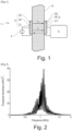
- figure 1 Such an acoustic transmission system for power transmission.
- This system 1 comprises an acoustic transmitter 2 and an acoustic receiver 3 in contact on either side of a metal wall P.
- the acoustic transmitter 2 consists of a piezoelectric disk 20 interposed between two electrodes 21, 22.
- the acoustic receiver 2 also consists of a piezoelectric disk 30 interposed between two electrodes 31, 32.
- An electrical power source 4 is connected to the two electrodes 21, 22 of the transmitter 2.
- the two electrodes 31, 32 of the receiver are connected to an electronic unit 5 adapted to manage the electrical power and which includes a sensor node.
- the operation of such a system 1 is as follows:
- the electrical power from the source 4 is transmitted by applying a sinusoidal voltage to the electrodes 21, 22 which cause the piezoelectric disk 20 to mechanically vibrate.
- the mechanical deformations resulting from this voltage propagate in the thickness of the metal wall P and are transmitted to the piezoelectric disk 30 of the receiver 3 which are therefore converted into electricity.
- the electronic unit 5 can manage the electrical power received.
- the inventors analyzed that to maximize the transmitted acoustic power, it was wise to determine both the optimal frequency and the electrical load to be connected at the acoustic receiver.
- US2015/0049587 suggests choosing the frequency allowing the highest voltage on the storage capacity connected to the receiver. This requires having previously established communication so that the receiver can send the capacity charge level. In addition, this solution does not make it possible to determine the electrical load to be connected.
- US2014/0016558 characterizes the acoustic system prior to any transmission.
- the optimal electrical load to connect to the receiver is determined initially with a vector network analyzer. This involves having physical access to both sides of the metal wall, which is not systematically achievable depending on the applications. Furthermore, this determination made initially is no longer necessarily valid during operation, and if conditions change, for example in the event of a change in temperature.
- the frequency is chosen by communicating to the transmitter the power received by the receiver. However, this implies having previously established communication so that the receiver can communicate data.
- US2010/0027379 describes an operation in which the frequency determined is by the greatest amplitude of the signal received. This requires having previously established communication so that the receiver can send the amplitude of the signal received. No determination of electrical load to be connected is made.
- the existing solutions described above do not make it possible to choose the optimal frequency to maximize power transmission without data communication being previously established with the receiver, nor do they make it possible to choose the electrical load to be connected to the receiver level, before and during operation, also to maximize power transmission.
- An aim of the invention is to respond, at least partially, to this need.
- the acoustic system can comprise several transmitters and several acoustic receivers.
- each receiver is sized to be powered in a frequency range different from the other receivers.
- the dimensions of the receiver can be adjusted to resonate at a frequency within a predetermined frequency range.
- the method can then be performed in each of the respective frequency ranges to determine the characteristic frequency (fopt) which maximizes the transmitted power, receiver voltage or efficiency, for each of the receivers.
- the support is a particularly metallic wall, the transmitter and the receiver being arranged on the same side or on either side of the wall.
- the method according to the invention can be implemented for an acoustic transmission system through a support in any material which typically has a characteristic acoustic impedance of between 1 and 100 MRayl.
- the distinct electrical charges connected to the receiver during step ii/ are respectively an infinite charge corresponding to an open electrical circuit at the receiver, a charge of known value, and a zero charge corresponding to a short circuit at the receiver.
- the duration between each frequency scan is defined by the receiver which waits for a predefined duration, known to the transmitter.
- the duration between each frequency scan is defined by the receiver which indicates to the transmitter by an alternation of the connected load that it is ready, then changes the connected electrical load.
- the duration between each frequency sweep is defined by a change in the impedance on the transmitter side without active components on the receiver side.
- the invention essentially consists of a system for the transmission of acoustic power, which will determine the optimal frequency and electrical charge without data communication being previously established with the receiver.
- This adjustment can be made either by repeating the method described above, or through the communication then established between the transmitter and the receiver, allowing the sending of data describing the quality of the power transmission.
- the invention also relates to the application of the method which has just been described for sending electrical power through a metal wall, in particular a metal wall of a ship, a submarine, a tank, etc. 'a tank, a pipe.
- a method of operating an acoustic transmission system according to the invention is described below, making it possible to maximize the transmitted acoustic power.
- Step i/ We set up an acoustic transmission system 1 as shown on the figure 1 .
- This system 1 can be characterized as being an electric quadrupole schematized in Figure 3 .
- the inventors therefore thought of making three different measurements to be able to determine the values of Z 11 , Z 12 and Z 22 .
- Z load is the impedance of the load connected to receiver 3 ( Figure 3 ).
- the input impedance of the quadrupole also changes.
- Z 22 Z Load Z in CO ⁇ Z in Z Load Z in Z Load ⁇ Z in CC
- transmitter 2 is permanently supplied with this frequency.
- the transmitter can then trigger the complementary step iii2/ allowing it to determine the optimal electrical load applied to the receiver 3 in order to maximize the transmitted acoustic power.
- the inventors consider that the connected impedance has a significant impact on the recovered power.
- the inventors therefore thought of a method which allows them to overcome this iteration.
- system 1 can be considered as an equivalent electrical diagram obtained by application of Thévenin's theorem, as shown in Figure 4 .
- the first method implies that the receiver must then emit a sinusoidal voltage, which requires quite a lot of energy.
- the second method requiring less energy, the inventors favored it.
- these values can be when the loads are open-circuited and short-circuited.
- the phase between U 2 CO and I 2 CC is important to determine the real and imaginary parts of Z out .
- the optimal impedance to connect at the output can have a reactive component, as already mentioned.
- a difficulty is that the voltage U 2 CO and the current I 2 CC are measured in a time-shifted manner and that moreover, on the receiver side, there is no access to the signal U 1 transmitted.
- the first step consists of maintaining the voltage U 1 at transmitter 2, at a constant frequency for the entire duration of the two measurements, that is to say with the two different loads (open circuit and short circuit) without cutting the signal between the two measurements.
- the second step consists of measuring, on the receiver side 3, during the connection of the first load, the frequency and phase of the signal, the voltage U 2 or the current I 2 . For example, by setting a counter to zero, when U 2 or I 2 passes through zero (in increasing or decreasing value), and by recording the value of the counter at the next zero crossing of this current, in the same direction (increasing or decreasing). decreasing) just before resetting the counter to zero.
- the third step consists, just before disconnecting the first load, of continuing until obtaining the repetition of a phase element as if the signal were continuing.
- the counter is no longer set to zero when the voltage U 2 or the current I 2 crosses zero, but when the counter reaches the value which had been measured/recorded previously at the end of period.
- the phase of the current I 2 and/or the voltage I 2 can be compared to this phase element carried over/repeated. For example, it is possible to measure the temporal or angular distance between the zero crossing of the U 2 and/or I 2 signal with the theoretical zero crossing (when the counter returns to zero) of the U 2 or I 2 signal measured during the first charge as if the signal continued to exist.
- the impedance Z out can then be determined as well as the optimal electrical load.
- Steps ii/ and iii/ which have just been described, making it possible to determine the frequency and the load to be connected to maximize the power transmitted to the receiver 3, are synthesized on the Figure 5 .
- Steps ii/ and iii1/ were validated experimentally with system 1 on a 60 mm thick aluminum wall.
- the method according to the invention consists of choosing as distinct charges, a infinite charge (open circuit), zero charge (short circuit) and any charge other than infinite and zero.
- the method can be implemented regardless of the electrical loads connected, provided that they are distinct.
- the method detailed above concerns the determination of the frequency making it possible to maximize the transmitted power.
- the knowledge for each frequency of Z 11 , Z 12 and Z 22 makes it possible to predict the behavior of an acoustic transmission system and therefore to operate it with an optimized parameter depending on the desired application.
- the method detailed above is described in relation to acoustic transmission through a metal wall.
- the invention can also be applied to a support made of another material whose characteristic acoustic impedance is typically between 1 and 100 MRayl. It may be, for example, a material chosen from steel, aluminum and other metals, concrete, bitumen, wood, rigid plastics, porcelain, glass, etc.
- the method according to the invention can also be applied to inductive systems with air or with magnetic circuits, as long as the system remains linear, i.e. in small signals (far from the saturation of the magnetic materials).
- the method according to the invention is, however, more suited to the transmission of acoustic power, for which the optimal operating frequencies are difficult to predict, reproducible and strongly dependent on external variables such as temperature.
- the propagation medium is generally air, or otherwise an intermediate controlled/designed by the system designer and there are not as many hazards and impacts of the propagation medium.
- the invention is not limited to the examples which have just been described; In particular, it is possible to combine characteristics of the illustrated examples within non-illustrated variants.
Landscapes
- Engineering & Computer Science (AREA)
- Computer Networks & Wireless Communication (AREA)
- Power Engineering (AREA)
- Signal Processing (AREA)
- Transmitters (AREA)
- Measurement Of Resistance Or Impedance (AREA)
- Arrangements For Transmission Of Measured Signals (AREA)
Description
La présente invention concerne le domaine général des systèmes de transmission utilisant des ondes acoustiques.The present invention relates to the general field of transmission systems using acoustic waves.
Dans un système de transmission acoustique, des informations et/ou de l'énergie sont transmises entre un émetteur et un récepteur par voie acoustique. Les informations et/ou l'énergie sont ainsi transmises sans fil et sans contact.In an acoustic transmission system, information and/or energy is transmitted between a transmitter and a receiver acoustically. Information and/or energy are thus transmitted wirelessly and without contact.
Dans certaines applications, il est nécessaire de communiquer avec des capteurs placés de part et d'autre d'une ou plusieurs parois en métal.In certain applications, it is necessary to communicate with sensors placed on either side of one or more metal walls.
L'utilisation des techniques électromagnétiques (RFID, wifi, Bluetooth) n'est pas possible car les ondes électromagnétiques sont absorbées par une paroi métallique.The use of electromagnetic techniques (RFID, wifi, Bluetooth) is not possible because electromagnetic waves are absorbed by a metal wall.
Une solution qui peut être utilisée dans certaines applications, consiste à percer un trou dans la paroi pour y passer des fils. Cette solution nécessite de la maintenance et peut fragiliser la structure.A solution that can be used in certain applications consists of drilling a hole in the wall to pass wires through. This solution requires maintenance and can weaken the structure.
Une alternative en cours de recherche dans différents laboratoires consiste à mettre en oeuvre des systèmes de transmission utilisant les ondes acoustiques, car celles-ci se propagent bien à travers le métal.An alternative currently being researched in various laboratories consists of implementing transmission systems using acoustic waves, because these propagate well through metal.
En particulier, ils sont mis en oeuvre pour la transmission de puissance lorsqu'on souhaite alimenter électriquement le(s) récepteur(s), en particulier des capteurs isolés physiquement et leur système de communication, comme par exemple dans des réservoirs ou des canalisations sous fortes pressions.In particular, they are used for power transmission when it is desired to electrically power the receiver(s), in particular physically isolated sensors and their communication system, such as for example in tanks or pipes under strong pressures.
On a représenté schématiquement en
Ce système 1 comprend un émetteur acoustique 2 et un récepteur acoustique 3 en contact de part et d'autre d'une paroi métallique P.This
L'émetteur acoustique 2 est constitué d'un disque piézoélectrique 20 intercalé entre deux électrodes 21, 22.The
Le récepteur acoustique 2 est également constitué d'un disque piézoélectrique 30 intercalé entre deux électrodes 31, 32.The
Une source de puissance électrique 4 est reliée aux deux électrodes 21, 22 de l'émetteur 2.An
De l'autre côté de la paroi P, les deux électrodes 31, 32 du récepteur sont reliées à une unité électronique 5 adaptée pour gérer la puissance électrique et qui comprend un noeud de capteurs.On the other side of the wall P, the two
Le fonctionnement d'un tel système 1 est le suivant :
La puissance électrique de la source 4 est transmise en appliquant une tension sinusoïdale aux électrodes 21, 22 qui mettent en vibrations mécaniques le disque piézoélectrique 20. Les déformations mécaniques résultant de cette tension se propagent dans l'épaisseur de la paroi métallique P et sont transmises au disque piézoélectrique 30 du récepteur 3 qui sont donc converties en électricité.The operation of such a
The electrical power from the
Et l'unité électronique 5 peut gérer la puissance électrique reçue.And the
Avec un tel système 1, il est possible de faire passer de la puissance (flèche Pu en trait plein sur la
Un des défauts de la transmission de puissance acoustique à travers les parois métalliques est sa forte sélectivité en fréquence : cela est illustré à la
Il s'avère donc nécessaire d'alimenter l'émetteur acoustique à une fréquence favorable pour obtenir un bon fonctionnement.It is therefore necessary to power the acoustic transmitter at a favorable frequency to obtain good operation.
Par ailleurs, même si une caractérisation préalable est réalisée lors de l'installation du système, cette caractérisation ne sera pas fiable dans le temps, car les fréquences préférentielles sont fortement dépendantes de la température.Furthermore, even if a preliminary characterization is carried out during installation of the system, this characterization will not be reliable over time, because the preferential frequencies are strongly dependent on the temperature.
En outre, la caractérisation préalable n'est pas forcément possible selon les configurations.In addition, prior characterization is not necessarily possible depending on the configurations.
De manière générale, les inventeurs ont analysé que pour maximiser la puissance acoustique transmise, il était judicieux de déterminer à la fois la fréquence optimale et la charge électrique à connecter au niveau du récepteur acoustique.Generally speaking, the inventors analyzed that to maximize the transmitted acoustic power, it was wise to determine both the optimal frequency and the electrical load to be connected at the acoustic receiver.
Différentes solutions permettant de choisir la fréquence optimale de la transmission de puissance ont déjà été proposées.Different solutions making it possible to choose the optimal frequency of power transmission have already been proposed.
La demande de brevet
En résumé, les solutions existantes décrites ci-avant ne permettent pas de choisir la fréquence optimale pour maximiser la transmission de puissance sans qu'une communication de données ne soit préalablement établie avec le récepteur, ni ne permettent de choisir la charge électrique à connecter au niveau du récepteur, avant et pendant le fonctionnement, également pour maximiser la transmission de puissance.In summary, the existing solutions described above do not make it possible to choose the optimal frequency to maximize power transmission without data communication being previously established with the receiver, nor do they make it possible to choose the electrical load to be connected to the receiver level, before and during operation, also to maximize power transmission.
Par conséquent, il existe un besoin d'améliorer les solutions de fonctionnement d'un système de transmission acoustique, afin de pallier les inconvénients précités pour maximiser la puissance acoustique transmise.Consequently, there is a need to improve the operating solutions of an acoustic transmission system, in order to overcome the aforementioned drawbacks to maximize the transmitted acoustic power.
Un but de l'invention est de répondre, au moins partiellement à ce besoin.An aim of the invention is to respond, at least partially, to this need.
Pour ce faire, l'invention a tout d'abord pour objet un procédé de fonctionnement d'un système de transmission acoustique, comprenant les étapes suivantes :
- i/ mise en place du système à au moins un émetteur et au moins un récepteur acoustique sur un support, le système étant un quadripôle électrique dont la matrice d'impédance, liant les tensions d'émetteur (U1) et de récepteur (U2) aux courants d'émetteur (I1) et de récepteur (I2), s'écrit selon l'équation :

- ii/ balayage en fréquence en trois fois consécutivement avec à chaque fois une charge électrique connectée au récepteur Zload distincte de celle qui précède, de sorte à déterminer, pour chaque fréquence, les valeurs de Z11, Z12 et de Z22 ;
- iii/ à partir de la détermination des valeurs de Z11, Z12 et de Z22, détermination d'une fréquence caractéristique (fopt) afin de maximiser la puissance transmise, la tension de récepteur (U2) ou le rendement du système.
- i/ installation of the system with at least one transmitter and at least one acoustic receiver on a support, the system being an electrical quadrupole whose impedance matrix, linking the transmitter (U 1 ) and receiver (U) voltages 2 ) to the transmitter (I 1 ) and receiver (I 2 ) currents, is written according to the equation:
- ii/ frequency scanning in three consecutive times, each time with an electrical load connected to the receiver Z load distinct from that which precedes, so as to determine, for each frequency, the values of Z 11 , Z 12 and Z 22 ;
- iii/ from the determination of the values of Z 11 , Z 12 and Z 22 , determination of a characteristic frequency (f opt ) in order to maximize the transmitted power, the receiver voltage (U 2 ) or the efficiency of the system .
Selon un mode de réalisation avantageux, l'étape iii/ comprenant les sous-étapes suivantes :
- iii1/ détermination de la fréquence caractéristique (fopt) à partir de la détermination de la puissance maximale atteignable à chaque fréquence (f) par la relation,

- iii2/ application de deux charges électriques connectées au récepteur Zload distinctes entre elles, lors de l'émission d'un signal sinusoïdal par l'émetteur, de sorte à déterminer la charge électrique optimale, à partir du théorème de Thévenin et la relation

- la détermination de la fréquence caractéristique et la charge électrique optimale permettant de maximiser la puissance transmise.
- iii1/ determination of the characteristic frequency (fopt) from the determination of the maximum power achievable at each frequency (f) by the relationship,
- iii2/ application of two electrical loads connected to the receiver Zload distinct from each other, during the emission of a sinusoidal signal by the transmitter, so as to determine the optimal electrical charge, from Thévenin's theorem and the relationship
- determining the characteristic frequency and the optimal electrical load to maximize the transmitted power.
Selon un mode de réalisation avantageux, le système acoustique peut comprendre plusieurs émetteurs et plusieurs récepteurs acoustiques. Dans un tel mode, chaque récepteur est dimensionné pour être alimenté dans une plage de fréquence différente des autres récepteurs. Par exemple, on peut réaliser un ajustement des dimensions du récepteur pour résonner à une fréquence à l'intérieure d'une plage de fréquence prédéterminée.According to an advantageous embodiment, the acoustic system can comprise several transmitters and several acoustic receivers. In such a mode, each receiver is sized to be powered in a frequency range different from the other receivers. For example, the dimensions of the receiver can be adjusted to resonate at a frequency within a predetermined frequency range.
Le procédé peut alors être exécuté dans chacune des plages de fréquence respectives pour déterminer la fréquence caractéristique (fopt) qui maximise la puissance transmise, la tension de récepteur ou le rendement, pour chacun des récepteurs.The method can then be performed in each of the respective frequency ranges to determine the characteristic frequency (fopt) which maximizes the transmitted power, receiver voltage or efficiency, for each of the receivers.
Selon une configuration, le support est une paroi notamment métallique, l'émetteur et le récepteur étant agencés du même côté ou de part et d'autre de la paroi. Le procédé selon l'invention peut être mis en oeuvre pour un système de transmission acoustique à travers un support dans n'importe quel matériau qui présente typiquement une impédance acoustique caractéristique comprise entre 1 et 100 MRayl.According to one configuration, the support is a particularly metallic wall, the transmitter and the receiver being arranged on the same side or on either side of the wall. The method according to the invention can be implemented for an acoustic transmission system through a support in any material which typically has a characteristic acoustic impedance of between 1 and 100 MRayl.
Avantageusement, les charges électriques distinctes connectées au récepteur lors de l'étape ii/ sont respectivement une charge infinie correspondant à un circuit électrique ouvert au récepteur, une charge de valeur connue, et une charge nulle correspondant à un court-circuit au récepteur.Advantageously, the distinct electrical charges connected to the receiver during step ii/ are respectively an infinite charge corresponding to an open electrical circuit at the receiver, a charge of known value, and a zero charge corresponding to a short circuit at the receiver.
Selon une première variante, la durée entre chaque balayage de fréquence est définie par le récepteur qui attend une durée prédéfinie, connue de l'émetteur.According to a first variant, the duration between each frequency scan is defined by the receiver which waits for a predefined duration, known to the transmitter.
Selon une deuxième variante, la durée entre chaque balayage de fréquence est définie par le récepteur qui indique à l'émetteur par une alternance de la charge connectée qu'il est prêt, puis change la charge électrique connectée.According to a second variant, the duration between each frequency scan is defined by the receiver which indicates to the transmitter by an alternation of the connected load that it is ready, then changes the connected electrical load.
Selon une troisième variante, la durée entre chaque balayage de fréquence est définie par un changement de l'impédance du côté de l'émetteur sans composants actifs du côté du récepteur.According to a third variant, the duration between each frequency sweep is defined by a change in the impedance on the transmitter side without active components on the receiver side.
Selon un mode de réalisation avantageux, l'étape iii/ comprend les sous-étapes suivantes :
- iii1/ détermination de la fréquence caractéristique (fopt) à partir de la détermination de la puissance maximale atteignable à chaque fréquence (f) par la relation,

- iii2/ application de deux charges électriques connectées au récepteur Zload distinctes entre elles, lors de l'émission d'un signal sinusoïdal par l'émetteur, de sorte à déterminer la charge électrique optimale, à partir du théorème de Thévenin et la relation

- la détermination de la fréquence caractéristique et la charge électrique optimale permettant de maximiser la puissance transmise.
- iii1/ determination of the characteristic frequency (fopt) from the determination of the maximum power achievable at each frequency (f) by the relationship,
- iii2/ application of two electrical loads connected to the receiver Zload distinct from each other, during the emission of a sinusoidal signal by the transmitter, so as to determine the optimal electrical charge, from Thévenin's theorem and the relationship
- determining the characteristic frequency and the optimal electrical load to maximize the transmitted power.
L'étape iii2/ comprend l'une ou l'autre des étapes suivantes :
- le maintien de la tension U1 à l'émetteur à une fréquence constante ;
- l'application d'une des deux charges électriques distinctes sans coupure du signal par l'émetteur ;
- la mesure, du côté du récepteur, durant la connexion de la première charge électrique, de l'amplitude du signal de la tension U2 ou du courant I2 ;
- avant la déconnexion de la première charge électrique, la répétition d'un élément de phase comme si le signal sinusoïdal U2 ou I2 était poursuivi ;
- l'application de la deuxième charge électrique ;
- la mesure de l'amplitude de U2 ou I2 et de la phase avec le signal poursuivi avant la déconnexion de la première charge.
- maintaining the voltage U1 at the transmitter at a constant frequency;
- the application of one of two distinct electrical charges without cutting the signal by the transmitter;
- measuring, on the receiver side, during the connection of the first electrical load, the amplitude of the signal of the voltage U2 or the current I2;
- before disconnection of the first electrical load, the repetition of a phase element as if the sinusoidal signal U2 or I2 were continued;
- applying the second electric charge;
- measuring the amplitude of U2 or I2 and the phase with the signal pursued before disconnection of the first load.
Ainsi, l'invention consiste essentiellement en un système pour la transmission de puissance acoustique, qui va déterminer la fréquence et la charge électrique optimales sans qu'une communication de données ne soit préalablement établie avec le récepteur.Thus, the invention essentially consists of a system for the transmission of acoustic power, which will determine the optimal frequency and electrical charge without data communication being previously established with the receiver.
Une fois la fréquence et la charge électrique optimales déterminées, la transmission de puissance se fait correctement, et il est possible d'établir la communication.Once the optimal frequency and electrical load are determined, power transmission occurs correctly, and it is possible to establish communication.
Afin de conserver la puissance optimale, il est nécessaire d'ajuster régulièrement les valeurs de fréquence et de charge électrique.In order to maintain optimal power, it is necessary to regularly adjust the frequency and electrical load values.
Cet ajustement peut être réalisé soit en réitérant la méthode décrite ci-dessus, soit grâce à la communication alors établie entre l'émetteur et le récepteur, permettant l'envoi de données décrivant la qualité de la transmission de puissance.This adjustment can be made either by repeating the method described above, or through the communication then established between the transmitter and the receiver, allowing the sending of data describing the quality of the power transmission.
Les avantages de l'invention sont nombreux parmi lesquels on peut citer un gain important dans la robustesse de systèmes de transmission de puissance acoustique.The advantages of the invention are numerous, among which we can cite a significant gain in the robustness of acoustic power transmission systems.
L'invention concerne également l'application du procédé qui vient d'être décrit pour envoyer de la puissance électrique à travers une paroi métallique, notamment une paroi métallique d'un navire, d'un sous-marin, d'un réservoir, d'une cuve, d'un tuyau.The invention also relates to the application of the method which has just been described for sending electrical power through a metal wall, in particular a metal wall of a ship, a submarine, a tank, etc. 'a tank, a pipe.
D'autres avantages et caractéristiques ressortiront mieux à la lecture de la description détaillée, faite à titre illustratif et non limitatif, en référence aux figures suivantes.Other advantages and characteristics will become clearer on reading the detailed description, given for illustrative and non-limiting purposes, with reference to the following figures.
-
[
Fig 1 ] lafigure 1 est une représentation schématique montrant un exemple de système de transmission acoustique à travers une paroi métallique conforme à l'invention.[Figure 1 ] therefigure 1 is a schematic representation showing an example of an acoustic transmission system through a metal wall according to the invention. -
[
Fig 2 ] lafigure 2 illustre le spectre de puissance acoustique normalisée en fonction de la fréquence, obtenue à travers une paroi métallique selon l'état de l'art.[Figure 2 ] therefigure 2 illustrates the acoustic power spectrum normalized as a function of frequency, obtained through a metal wall according to the state of the art. -
[
Fig 3 ] lafigure 3 est une représentation sous la forme d'un quadripôle électrique d'un système de transmission acoustique à travers une paroi métallique.[Figure 3 ] thereFigure 3 is a representation in the form of an electric quadrupole of an acoustic transmission system through a metal wall. -
[
Fig 4 ] lafigure 4 représente le schéma électrique équivalent du quadripôle selon lafigure 3 obtenu par application du théorème de Thévenin.[Figure 4 ] thereFigure 4 represents the equivalent electrical diagram of the quadrupole according to theFigure 3 obtained by application of Thévenin's theorem. -
[
Fig 5 ] lafigure 5 est un diagramme bloc des séquences des étapes essentielles du procédé de fonctionnement selon l'invention.[Figure 5 ] thereFigure 5 is a block diagram of the sequences of the essential steps of the operating method according to the invention. -
[
Fig 6 ] lafigure 6 illustre sous forme de spectres, la matrice d'impédance et de la puissance transmise à partir de l'émetteur d'un système de transmission acoustique, en appliquant les séquences de l'étape de détermination de la charge électrique du procédé selon l'invention.[Figure 6 ] thereFigure 6 illustrates in the form of spectra, the impedance matrix and the power transmitted from the transmitter of an acoustic transmission system, by applying the sequences of the step of determining the electrical charge of the method according to the invention . -
[
Fig 7 ] lafigure 7 est un diagramme bloc des séquences des étapes essentielles du procédé de fonctionnement selon l'invention, sous forme de grafcet, tel qu'il peut être mis en oeuvre par un programme d'ordinateur au sein de l'unité de contrôle d'un système de transmission acoustique.[Figure 7 ] thereFigure 7 is a block diagram of the sequences of the essential steps of the operating method according to the invention, in grafcet form, such as it can be implemented by a computer program within the control unit of a system acoustic transmission.
Les
On décrit ci-après un procédé de fonctionnement d'un système de transmission acoustique selon l'invention permettant de maximiser la puissance acoustique transmise.A method of operating an acoustic transmission system according to the invention is described below, making it possible to maximize the transmitted acoustic power.
Etape i/ : On met en place un système de transmission acoustique 1 tel que montré sur la
Ce système 1 peut être caractérisé comme étant un quadripôle électrique schématisé en
De plus, ce système est linéaire, même pour de grandes amplitudes d'excitations : voir publication 1.Furthermore, this system is linear, even for large excitation amplitudes: see
Il peut donc être correctement décrit par sa matrice d'impédance, les tensions d'émetteur (U1) et de récepteur (U2) aux courants d'émetteur (I1) et de récepteur (I2), selon l'équation : 
Ainsi, pour chaque fréquence, la connaissance de Z11, Z12, Z21, et Z22, permet de déterminer le comportement du système.Thus, for each frequency, knowledge of Z 11 , Z 12 , Z 21 , and Z 22 makes it possible to determine the behavior of the system.
Il est alors possible de déterminer la puissance transmise pour chaque fréquence permettant ainsi de choisir la fréquence optimale pour le maximum de puissance: voir publication 2.It is then possible to determine the power transmitted for each frequency, thus making it possible to choose the optimal frequency for maximum power: see
Le système est un quadripôle réciproque, d'où: Z12 = Z21.The system is a reciprocal quadrupole, hence: Z 12 = Z 21 .
Dans une configuration la plus contraignante, il est seulement possible d'avoir accès à l'émetteur 2, c'est-à-dire à l'entrée du quadripôle réciproque.In a most restrictive configuration, it is only possible to have access to
Pa conséquent, seule la mesure d'impédance d'entrée est possible.Therefore, only input impedance measurement is possible.
Les inventeurs ont donc pensé à faire trois mesures différentes pour pouvoir déterminer les valeurs de Z11, Z12 et Z22.The inventors therefore thought of making three different measurements to be able to determine the values of Z 11 , Z 12 and Z 22 .
L'impédance d'entrée Zin d'un quadripôle est donnée par: 
Dans laquelle Zload est l'impédance de la charge connectée au récepteur 3 (
Lorsque l'impédance électrique connectée au niveau du récepteur est changée, l'impédance d'entrée du quadripôle change également.When the electrical impedance connected at the receiver is changed, the input impedance of the quadrupole also changes.
Changer trois fois l'impédance de charge connectée sur le récepteur, permet de déterminer Z11, Z12 et Z22.Changing the load impedance connected to the receiver three times makes it possible to determine Z 11 , Z 12 and Z 22 .
Cette méthode fonctionne pour trois impédances Z connectées différentes.This method works for three different connected Z impedances.
Par exemple, les trois impédances différentes peuvent être :
- lorsqu'un circuit-ouvert est appliqué, alors ZLoad = +∞ ,
- lorsqu'une impédance de valeur connue est appliquée, alors ZLoad = Z
- lorsqu'un circuit fermé est appliqué, alors ZLoad = 0.
- when an open circuit is applied, then Z Load = +∞,
- when an impedance of known value is applied, then Z Load = Z
- when a closed circuit is applied, then Z Load = 0.
Ainsi, pour une mesure de l'impédance d'entrée avec un circuit-ouvert sur la sortie ( ![]()
![]()
![]()
![]()
Pour une mesure de l'impédance d'entrée avec une charge connue sur la sortie ( ![]()

![]()
Et donc, 
Pour une mesure de l'impédance d'entrée avec, lorsque la sortie est court-circuitée ( ![]()

![]()
Et donc, 
Avec ces trois mesures, les valeurs de Z11, Z12 et Z22 sont ainsi déterminées.With these three measurements, the values of Z 11 , Z 12 and Z 22 are thus determined.
Il est alors possible d'appliquer les formules données dans la publication 2, afin d'obtenir la puissance transmise normalisée par la tension d'entrée.It is then possible to apply the formulas given in
La puissance transmise normalisée est donnée par : 
Avec 
Aussi, la puissance normalisée est maximisée pour chaque fréquence f lorsque : 
En remplaçant cette expression dans celle de la puissance, la puissance maximale atteignable à chaque fréquence est : 
![]()
![]()
Par conséquent, en réalisant trois balayages en fréquence, en changeant pour chaque balayage la charge électrique connectée sur le récepteur (Z différent à chaque balayage), la fréquence qui maximise la puissance de sortie peut être déterminée.Therefore, by performing three frequency sweeps, changing for each sweep the electrical load connected to the receiver (Z different with each sweep), the frequency which maximizes the output power can be determined.
Changer la charge connectée au niveau du récepteur ne demande que très peu d'énergie. Il est donc possible de déterminer la fréquence optimale avec très peu d'énergie stockée côté récepteur 3, en ayant accès qu'au côté émetteur 2 du système.Changing the load connected to the receiver requires very little energy. It is therefore possible to determine the optimal frequency with very little energy stored on the receiver side 3, having access only to the
Une fois la fréquence optimale trouvée, l'émetteur 2 est alimenté en permanence avec cette fréquence.Once the optimal frequency has been found,
L'émetteur peut alors déclencher l'étape iii2/ complémentaire lui permettant de déterminer la charge électrique optimale appliquée au niveau du récepteur 3 afin de maximiser la puissance acoustique transmise.The transmitter can then trigger the complementary step iii2/ allowing it to determine the optimal electrical load applied to the receiver 3 in order to maximize the transmitted acoustic power.
Les inventeurs considèrent que l'impédance connectée a un impact important sur la puissance récupérée.The inventors consider that the connected impedance has a significant impact on the recovered power.
En effet, en considérant une variation de charge résistive de 0 à l'infini, on récupère de la puissance électrique, c'est-à-dire celle dissipée par la résistance. Pour ces deux extrêmes, la puissance récupérée est nulle (tension nulle ou courant nul).Indeed, by considering a variation in resistive load from 0 to infinity, we recover electrical power, that is to say that dissipated by the resistance. For these two extremes, the power recovered is zero (zero voltage or zero current).
Il existe donc une puissance maximale à récupérer.There is therefore a maximum power to recover.
Trouver cette puissance maximale par itération est très long puisqu'il s'agit de tester toutes les charges électriques possibles du côté du récepteur, celles-ci étant par ailleurs résistives et réactives.Finding this maximum power per iteration is very long since it involves testing all possible electrical loads on the receiver side, these being resistive and reactive.
Les inventeurs ont donc pensé à une méthode qui permet de s'affranchir de cette itération.The inventors therefore thought of a method which allows them to overcome this iteration.
Puisque, le système de transmission acoustique 1 est linéaire, alors les inventeurs considèrent que le théorème de Thévenin peut être appliqué.Since the
Pour rappel, ce théorème s'énonce comme suit : « Un réseau électrique linéaire vu de deux points est équivalent à un générateur de tension parfait dont la force électromotrice est égale à la différence de potentiels à vide entre ces deux points, en série avec une impédance égale à celle que l'on mesure entre les deux points lorsque les générateurs indépendants sont rendus passifs ». As a reminder, this theorem is stated as follows: “A linear electrical network seen from two points is equivalent to a perfect voltage generator whose electromotive force is equal to the difference in no-load potentials between these two points, in series with a impedance equal to that which is measured between the two points when the independent generators are made passive.
Ainsi, le système 1 peut être considéré comme un schéma électrique équivalent obtenu par application du théorème de Thévenin, tel que montré à la
Par application du théorème de la puissance maximale, la puissance sur la charge Zout est maximale lorsque : ![]()
![]()
![]()
![]()
Dans le cas d'une charge purement résistive, la puissance transmise sur la charge est maximale lorsque ZLoad = |Zout |.In the case of a purely resistive load, the power transmitted to the load is maximum when Z Load = | Z out |.
Ainsi, la connaissance de Zout permet de déterminer la charge électrique optimale pour obtenir le maximum de puissance.Thus, knowledge of Z out makes it possible to determine the optimal electrical load to obtain maximum power.
Il s'agit donc de déterminer Zout. Cette grandeur complexe (résistive et réactive) peut être déterminée selon deux méthodes différentes :
- soit en court-circuitant l'émetteur et en mesurant l'impédance de sortie ;
- soit en réalisant deux mesures successives sur la sortie (récepteur) lorsque l'émetteur émet un signal sinusoïdal.
- either by short-circuiting the transmitter and measuring the output impedance;
- or by carrying out two successive measurements on the output (receiver) when the transmitter emits a sinusoidal signal.
La première méthode implique que le récepteur doive alors émettre une tension sinusoïdale, ce qui nécessite une énergie assez importante.The first method implies that the receiver must then emit a sinusoidal voltage, which requires quite a lot of energy.
Aussi, la deuxième méthode nécessitant moins d'énergie, les inventeurs l'ont privilégié.Also, the second method requiring less energy, the inventors favored it.
Selon cette deuxième méthode, en considérant, [Equation10] : Uéq + ZoutI 2 = U 2 , il existe deux variables (Uéq, Zout ).According to this second method, considering, [Equation10]: U éq + Z out I 2 = U 2 , there exist two variables ( U éq , Z out ).
Il faut donc deux équations pour les déterminer. Celles-ci sont obtenues en connectant sur le récepteur 3, deux impédances de valeurs différentes.We therefore need two equations to determine them. These are obtained by connecting two impedances of different values to receiver 3.
Par exemple, ces valeurs peuvent être lorsque les charges sont en circuit-ouvert et court-circuit.For example, these values can be when the loads are open-circuited and short-circuited.
Lorsque le récepteur 3 est en circuit-ouvert, I 2 = 0, et alors ![]()
![]()
En court-circuitant le récepteur 3, U 2 = 0, ce qui permet de déterminer Zout selon : ![]()
![]()
D'où : 
La phase entre U2 CO et I2 CC est importante pour déterminer les partie réelles et imaginaires de Zout. En effet, l'impédance optimale à connecter en sortie peut avoir une composante réactive, comme déjà mentionné.The phase between U 2 CO and I 2 CC is important to determine the real and imaginary parts of Z out . Indeed, the optimal impedance to connect at the output can have a reactive component, as already mentioned.
Une difficulté est que la tension U2 CO et le courant I2 CC sont mesurés de manière décalée dans le temps et que par ailleurs, coté récepteur, il n'y a pas d'accès au signal U1 émis.A difficulty is that the voltage U 2 CO and the current I 2 CC are measured in a time-shifted manner and that moreover, on the receiver side, there is no access to the signal U 1 transmitted.
Il n'est alors pas possible de faire une mesure directe de déphasage entre U2 CO et I2 CC, ni entre U2 CO et U1, ni entre I2 CC et U1.It is then not possible to make a direct measurement of phase shift between U 2 CO and I 2 CC , nor between U 2 CO and U 1 , nor between I 2 CC and U 1 .
Pour contourner cette difficulté, les inventeurs ont pensé à une solution en plusieurs étapes.To get around this difficulty, the inventors thought of a solution in several stages.
La première étape consiste à maintenir la tension U1 à l'émetteur 2, à une fréquence constante pendant toute la durée des deux mesures, c'est à dire avec les deux charges différentes (circuit ouvert et court-circuit) sans coupure du signal entre les deux mesures.The first step consists of maintaining the voltage U 1 at
La deuxième étape consiste à mesurer, du côté récepteur 3, durant la connexion de la première charge, la fréquence et la phase du signal, de la tension U2 ou du courant I2. Par exemple, en mettant à zéro un compteur, lorsque U2 ou I2 passe par zéro (en valeur croissante ou décroissante), et en enregistrant la valeur du compteur au prochain passage par zéro de ce courant, dans la même direction (croissante ou décroissante) juste avant de remettre le compteur à zéro.The second step consists of measuring, on the receiver side 3, during the connection of the first load, the frequency and phase of the signal, the voltage U 2 or the current I 2 . For example, by setting a counter to zero, when U 2 or I 2 passes through zero (in increasing or decreasing value), and by recording the value of the counter at the next zero crossing of this current, in the same direction (increasing or decreasing). decreasing) just before resetting the counter to zero.
La troisième étape consiste, juste avant la déconnexion de la première charge, à poursuivre jusqu'à obtenir la répétition d'un élément de phase comme si le signal se poursuivait. Par exemple, dans l'exemple du compteur, le compteur n'est plus mis à zéro au passage par zéro de la tension U2 ou du courant I2, mais lorsque le compteur atteint la valeur qui avait été mesurée/enregistrée précédemment en fin de période.The third step consists, just before disconnecting the first load, of continuing until obtaining the repetition of a phase element as if the signal were continuing. For example, in the example of the counter, the counter is no longer set to zero when the voltage U 2 or the current I 2 crosses zero, but when the counter reaches the value which had been measured/recorded previously at the end of period.
Ainsi, lorsque la deuxième valeur de charge est connectée, la phase du courant I2 et/ou de la tension I2 peut être comparée à cet élément de phase reconduit/répété. Par exemple, il est possible de mesurer la distance temporelle ou angulaire entre le passage par zéro du signal U2 et/ou I2 avec le passage par zéro théorique (au retour à zéro du compteur) du signal U2 ou I2 mesuré durant la première charge comme si le signal continuait d'exister.Thus, when the second load value is connected, the phase of the current I 2 and/or the voltage I 2 can be compared to this phase element carried over/repeated. For example, it is possible to measure the temporal or angular distance between the zero crossing of the U 2 and/or I 2 signal with the theoretical zero crossing (when the counter returns to zero) of the U 2 or I 2 signal measured during the first charge as if the signal continued to exist.
Par « juste avant », on entend en pratique, une compensation du délai associé si nécessaire en remettant le compteur à 1, ou quelques coups d'horloge, au lieu de zéro pour compenser le retard induit dans la mise à zéro.By "just before", we mean in practice, compensation for the associated delay if necessary by resetting the counter to 1, or a few clock ticks, instead of zero to compensate for the delay induced in setting to zero.
L'impédance Zout peut alors être déterminée ainsi que la charge électrique optimale.The impedance Z out can then be determined as well as the optimal electrical load.
Les étapes ii/ et iii/ qui viennent d'être décrites permettant de déterminer la fréquence et la charge à connecter pour maximiser la puissance transmise au récepteur 3 sont synthétisées sur la
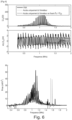
Les étapes ii/ et iii1/ ont été validées expérimentalement avec un système 1 sur une paroi en aluminium de 60 mm d'épaisseur.Steps ii/ and iii1/ were validated experimentally with
Les spectres obtenus tels que montrés à la
Comme déjà mentionné, lors des balayages en fréquence réalisés durant les étapes ii/ et iiil/, il est nécessaire de changer trois fois la charge électrique connectée au niveau du récepteur. Chaque changement de charge électrique doit être fait après la fin du balayage en fréquence en cours, et avant le début du balayage suivant, afin d'éviter de perturber fortement la mesure.As already mentioned, during the frequency sweeps carried out during steps ii/ and iiil/, it is necessary to change the electrical load connected to the receiver three times. Each change in electrical charge must be made after the end of the current frequency sweep, and before the start of the next sweep, in order to avoid strongly disturbing the measurement.
La durée nécessaire pour le changement peut être définie selon les trois alternatives suivantes qui peuvent être combinées :
- a/ Attente d'une durée prédéfinie : en définissant une durée d'attente, préalablement connue de l'émetteur et du récepteur. Le récepteur attend ainsi cette durée d'attente connue de l'émetteur après la fin du premier balayage en fréquence, avant de changer la charge électrique connectée ;
- b/ Attente d'une information de la part du récepteur : le récepteur indique à l'émetteur par une alternance de la charge connectée qu'il est prêt pour la suite des mesures et va changer la charge connectée. Cette variation au niveau du récepteur est visible du côté de l'émetteur et est utilisée parfois comme méthode de communication : [4].
- c/ Observation de l'impédance d'entrée et à partir de cette mesure, détection d'un changement d'impédance de sortie : lorsque le système est symétrique (paroi symétrique et émetteur et récepteur identiques), Z11=Z22. Avec cette contrainte, deux charges électriques seulement sont nécessaires pour caractériser le système. Ces deux charges peuvent être appliquées de manière passive sur le récepteur grâce à un pont de diodes et une capacité connectés au niveau du récepteur. Lors d'un premier balayage, la capacité est déchargée et impose une tension nulle, le comportement en entrée du pont de diode est donc équivalent à un circuit-fermé. En réalisant plusieurs balayages en fréquence, la tension va augmenter aux bornes de la capacité, ce qui se traduit par des phases de conduction et de non-conduction des diodes. Ce comportement non linéaire va pouvoir être analysé au niveau de l'émetteur via une variation de l'impédance d'entrée. L'émetteur peut alors réduire le niveau de tension d'excitation afin que la tension sur le pont de diode soit toujours inférieure à la tension de la capacité. Les diodes sont donc bloquantes 100% du temps et l'impédance connectée au récepteur est un circuit-ouvert. Il est alors possible de caractériser le système sans rien changer au niveau du récepteur.
- a/ Waiting for a predefined duration : by defining a waiting duration, previously known to the transmitter and the receiver. The receiver thus waits for this waiting time known to the transmitter after the end of the first frequency sweep, before changing the connected electrical load;
- b/ Waiting for information from the receiver : the receiver indicates to the transmitter by alternating the connected load that it is ready for further measurements and will change the connected load. This variation at the receiver is visible on the transmitter side and is sometimes used as a method of communication: [4].
- c/ Observation of the input impedance and from this measurement, detection of a change in output impedance : when the system is symmetrical (symmetrical wall and identical transmitter and receiver), Z 11 =Z 22 . With this constraint, only two electrical charges are necessary to characterize the system. These two loads can be applied passively to the receiver thanks to a diode bridge and a capacitor connected at the receiver. During a first scan, the capacitor is discharged and imposes a zero voltage, the behavior at the input of the diode bridge is therefore equivalent to a closed circuit. By carrying out several frequency sweeps, the voltage will increase across the capacitance, which results in conduction and non-conduction phases of the diodes. This non-linear behavior will be able to be analyzed at the transmitter level via a variation of the input impedance. The emitter can then reduce the excitation voltage level so that the voltage on the diode bridge is always lower than the capacitance voltage. The diodes are therefore blocking 100% of the time and the impedance connected to the receiver is an open circuit. It is then possible to characterize the system without changing anything at the receiver level.
La
Sur cette
- Cond1E : au choix ou en combinaison:
- a/ Attente d'une durée prédéfinie,
- b/ Attente d'une information de la part du récepteur (exemple: modulation de charge),
- c/ Observation de l'impédance d'entrée et à partir de cette mesure, détection d'un changement d'impédance de sortie.
- Cond2E : au choix ou en combinaison :
- a/ Attente d'une durée prédéfinie,
- b/ Attente d'une information de la part du récepteur (exemple : modulation de charge),
- c/ Observation de l'impédance d'entrée et à partir de cette mesure, détection d'un changement d'impédance de sortie.
- Cond3E : au choix ou en combinaison :
- a/ Attente d'une durée prédéfinie,
- b/ Attente d'une information de la part du récepteur (ex: modulation de charge, ou communication sur une autre bande de fréquence).
- Cond1R : au choix ou en combinaison :
- a/ Attente d'une durée prédéfinie,
- b1/ Attente d'un certain niveau de tension/d'énergie,
- c1/ Attente d'une certaine fréquence reçue.
- Cond2R : au choix ou en combinaison:
- a/ Attente d'une durée prédéfinie,
- b1/ Attente d'un certain niveau de tension/d'énergie,
- c1/ Attente d'une certaine fréquence reçue.
- Cond3R : au choix ou en combinaison :
- a/ Attente d'une durée prédéfinie,
- b1/ Attente d'un certain niveau de tension/d'énergie,
- c1/ Attente d'une certaine fréquence reçue.
- Cond1E: choice or combination:
- a/ Waiting for a predefined duration,
- b/ Waiting for information from the receiver (example: load modulation),
- c/ Observation of the input impedance and from this measurement, detection of a change in output impedance.
- Cond2E: as desired or in combination:
- a/ Waiting for a predefined duration,
- b/ Waiting for information from the receiver (example: load modulation),
- c/ Observation of the input impedance and from this measurement, detection of a change in output impedance.
- Cond3E: as desired or in combination:
- a/ Waiting for a predefined duration,
- b/ Waiting for information from the receiver (e.g. load modulation, or communication on another frequency band).
- Cond1R: choice or combination:
- a/ Waiting for a predefined duration,
- b1/ Waiting for a certain level of tension/energy,
- c1/ Waiting for a certain frequency received.
- Cond2R: as desired or in combination:
- a/ Waiting for a predefined duration,
- b1/ Waiting for a certain level of tension/energy,
- c1/ Waiting for a certain frequency received.
- Cond3R: as desired or in combination:
- a/ Waiting for a predefined duration,
- b1/ Waiting for a certain level of tension/energy,
- c1/ Waiting for a certain frequency received.
D'autres avantages et améliorations pourront être apportés sans pour autant sortir du cadre de l'invention.Other advantages and improvements could be made without departing from the scope of the invention.
Dans l'exemple détaillé, pour la détermination des paramètres du quadripôle (Z11, Z12 et Z22) et de la charge électrique optimale au récepteur (Zopt), la méthode selon l'invention consiste à choisir comme charges distinctes, une charge infinie (circuit ouvert), une charge nulle (court-circuit) et une charge quelconque autre qu'infinie et nulle. Cependant, la méthode peut être mise en oeuvre quelles que soient les charges électriques connectées, à condition que celles-ci soient distinctes.In the detailed example, for determining the parameters of the quadrupole (Z 11 , Z 12 and Z 22 ) and the optimal electrical load at the receiver (Z opt ), the method according to the invention consists of choosing as distinct charges, a infinite charge (open circuit), zero charge (short circuit) and any charge other than infinite and zero. However, the method can be implemented regardless of the electrical loads connected, provided that they are distinct.
Par ailleurs, la méthode détaillée ci-avant concerne la détermination de la fréquence permettant de maximiser la puissance transmise. Cependant, en fonction des besoins, il est tout à fait possible de choisir la fréquence maximisant la tension au récepteur U2 ou le rendement du système. En effet la connaissance pour chaque fréquence de Z11, Z12 et de Z22 permet de prédire le comportement d'un système de transmission acoustique et donc de le faire fonctionner avec un paramètre optimisé en fonction de l'application recherchée.Furthermore, the method detailed above concerns the determination of the frequency making it possible to maximize the transmitted power. However, depending on the needs, it is entirely possible to choose the frequency maximizing the voltage at the receiver U2 or the efficiency of the system. Indeed, the knowledge for each frequency of Z 11 , Z 12 and Z 22 makes it possible to predict the behavior of an acoustic transmission system and therefore to operate it with an optimized parameter depending on the desired application.
La méthode détaillée ci-avant est décrite en relation avec une transmission acoustique à travers une paroi métallique. L'invention peut aussi s'appliquer à un support en un autre matériau dont l'impédance acoustique caractéristique est typiquement comprise entre 1 et 100 MRayl. Il peut s'agit par exemple, d'un matériau choisi parmi les aciers, aluminium et autres métaux, béton, bitume, bois, plastiques rigides, porcelaine, verre...The method detailed above is described in relation to acoustic transmission through a metal wall. The invention can also be applied to a support made of another material whose characteristic acoustic impedance is typically between 1 and 100 MRayl. It may be, for example, a material chosen from steel, aluminum and other metals, concrete, bitumen, wood, rigid plastics, porcelain, glass, etc.
Par ailleurs, la méthode détaillée ci-avant est décrite en relation d'un émetteur et un récepteur agencés de part et d'autre d'une même paroi métallique. Elle s'applique aussi à un émetteur et un récepteur du même côté de la paroi, et plus généralement sur un même support.Furthermore, the method detailed above is described in relation to a transmitter and a receiver arranged on either side of the same metal wall. It also applies to a transmitter and a receiver on the same side of the wall, and more generally on the same support.
La méthode selon l'invention peut s'appliquer aussi pour les systèmes inductifs à air ou avec circuits magnétiques, tant que le système reste linéaire, soit en petits signaux (loin de la saturation des matériaux magnétiques).The method according to the invention can also be applied to inductive systems with air or with magnetic circuits, as long as the system remains linear, i.e. in small signals (far from the saturation of the magnetic materials).
La méthode selon l'invention est cependant plus adaptée à la transmission de puissance acoustique, pour lesquelles les fréquences optimales de fonctionnement sont difficilement prédictibles, reproductibles et dépendant fortement de variables extérieures telles que la température.The method according to the invention is, however, more suited to the transmission of acoustic power, for which the optimal operating frequencies are difficult to predict, reproducible and strongly dependent on external variables such as temperature.
Les fréquences optimales de fonctionnement sont difficilement prédictibles car le fonctionnement est très dépendant du milieu de transmission. En RF, le milieu de propagation est généralement l'air, ou sinon un intermédiaire maitrisé/conçu par le concepteur du système et il n'y a pas autant d'aléas et d'impacts du milieu de propagation. L'invention n'est pas limitée aux exemples qui viennent d'être décrits; on peut notamment combiner entre elles des caractéristiques des exemples illustrés au sein de variantes non illustrées.Optimal operating frequencies are difficult to predict because operation is very dependent on the transmission medium. In RF, the propagation medium is generally air, or otherwise an intermediate controlled/designed by the system designer and there are not as many hazards and impacts of the propagation medium. The invention is not limited to the examples which have just been described; In particular, it is possible to combine characteristics of the illustrated examples within non-illustrated variants.
-
1:
T. J. Lawry et al., « Electrical optimization of power delivery through thick steel barriers using piezoelectric transducers », in Energy Harvesting and Storage: Materials, Devices, and Applications, avr. 2010, vol. 7683, p. 768314, doi: 10.1117/12.852563 TJ Lawry et al., “Electrical optimization of power delivery through thick steel barriers using piezoelectric transducers,” in Energy Harvesting and Storage: Materials, Devices, and Applications, Apr. 2010, vol. 7683, p. 768314, doi: 10.1117/12.852563 -
2:
O. Freychet, F. Frassati, S. Boisseau, N. Garraud, P. Gasnier, et G. Despesse, «Analytical optimization ofpiezoelectric acoustic power transfer systems », Eng. Res. Express, vol. 2, no 4, p. 045022, nov. 2020, doi: 10. 1088/2631-8695/abcb4a O. Freychet, F. Frassati, S. Boisseau, N. Garraud, P. Gasnier, and G. Despesse, “Analytical optimization of piezoelectric acoustic power transfer systems”, Eng. Res. Express, vol. 2, no. 4, p. 045022, Nov. 2020, doi: 10. 1088/2631-8695/abcb4a -
3:
O. Freychet et al., « Efficient optimal load and maximum output power determination for linear vibration energy harvesters with a two-measurement characterization method », Smart Mater. Struct., vol. 29, no 1, p. 015003, nov. 2019, doi: 10.1088/1361-665X/ab516f O. Freychet et al., “Efficient optimal load and maximum output power determination for linear vibration energy harvesters with a two-measurement characterization method”, Smart Mater. Struct., vol. 29, no. 1, p. 015003, Nov. 2019, doi: 10.1088/1361-665X/ab516f -
4:
G. J. Saulnier et al., « P1G-4 Through-Wall Communication of Low-Rate Digital Data Using Ultrasound », in 2006 IEEE Ultrasonics Symposium, oct. 2006, p. 1385-1389, doi: 10.1109/ULTSYM.2006.358 GJ Saulnier et al., “P1G-4 Through-Wall Communication of Low-Rate Digital Data Using Ultrasound,” in 2006 IEEE Ultrasonics Symposium, Oct. 2006, p. 1385-1389, doi: 10.1109/ULTSYM.2006.358
Claims (13)
- Method for operating an acoustic transmission system, comprising the following steps:i/ installing the system (1) with at least one emitter (2) and at least one acoustic receiver (3) on a support, the system being an electric quadrupole whose impedance matrix, linking the emitter voltage (U1) and the receiver voltage (U2) to the emitter current (I1) and the receiver current (I2), is written using the equation:
 the quadrupole being reciprocal, with Z12 being equal to Z21; characterized in that the method comprises the steps of:ii/ performing frequency scanning three times in a row, each time with an electrical load connected to the receiver Zload distinct from the previous one, so as to determine the values of Z11, Z12 and Z22 for each frequency;iii/ based on the determination of the values of Z11, Z12 and Z22, determining a characteristic frequency (fopt) so as to maximize the transmitted power, the receiver voltage (U2) or the efficiency of the system.
 - Method according to Claim 1, the support being a wall, in particular a metal wall, the emitter and the receiver being arranged on the same side or on either side of the wall.
- Method according to Claim 1 or 2, the distinct electrical loads connected to the receiver in step ii/ being respectively an infinite load, corresponding to an open electrical circuit at the receiver, a load of known value, and a zero load, corresponding to a short circuit at the receiver.
- Method according to one of Claims 1 to 3, the duration between each frequency scan being defined by the receiver, which waits for a predefined duration that is known to the emitter.
- Method according to one of Claims 1 to 3, the duration between each frequency scan being defined by the receiver, which indicates to the emitter that it is ready by alternating the connected load, and then changes the connected electrical load.
- Method according to one of Claims 1 to 3, the duration between each frequency scan being defined by a change in impedance at the emitter without active components at the receiver.
- Method according to one of the preceding claims, step iii/ comprising the following sub-steps:iii1/ determining the characteristic frequency (fopt) based on the determination of the maximum power achievable at each frequency (f) using the relationship
 iii2/ applying two electrical loads connected to the receiver Zload that are distinct from one another, when a sinusoidal signal is emitted by the emitter, so as to determine the optimum electrical load based on Thévenin's theorem and the relationship
 determining the characteristic frequency and the optimum electrical load for maximizing the transmitted power.
 - Method according to Claim 7, step iii2/ comprising keeping the voltage U1 at the emitter (2) at a constant frequency and applying one of the two distinct electrical loads without the emitter disconnecting the signal.
- Method according to Claim 7, step iii2/ comprising measuring the amplitude of the signal of the voltage U2 or of the current 12 at the receiver (3) during the connection of the first electrical load.
- Method according to Claim 7, step iii2/ comprising, before disconnecting the first electrical load, repeating a phase element as though the sinusoidal signal were continued.
- Method according to Claim 7, step iii2/ comprising applying the second electrical load.
- Method according to Claim 7, step iii2/ comprising measuring the amplitude of U2 or 12 and the phase with the continued signal before disconnecting the first load.
- Application of the method according to one of the preceding claims in order to send electric power through a metal wall, in particular a metal wall of a vessel, a submarine, a tank, a container or a pipe.
Applications Claiming Priority (1)
| Application Number | Priority Date | Filing Date | Title |
|---|---|---|---|
| FR2102961A FR3121301B1 (en) | 2021-03-24 | 2021-03-24 | Method of operating an acoustic transmission system to optimize the transmitted power. |
Publications (2)
| Publication Number | Publication Date |
|---|---|
| EP4080791A1 EP4080791A1 (en) | 2022-10-26 |
| EP4080791B1 true EP4080791B1 (en) | 2023-10-04 |
Family
ID=76920848
Family Applications (1)
| Application Number | Title | Priority Date | Filing Date |
|---|---|---|---|
| EP22162402.6A Active EP4080791B1 (en) | 2021-03-24 | 2022-03-16 | Method for operating an acoustic transmission system for optimising the power transmitted |
Country Status (3)
| Country | Link |
|---|---|
| US (1) | US11791661B2 (en) |
| EP (1) | EP4080791B1 (en) |
| FR (1) | FR3121301B1 (en) |
Family Cites Families (9)
| Publication number | Priority date | Publication date | Assignee | Title |
|---|---|---|---|---|
| US20100027379A1 (en) | 2006-10-02 | 2010-02-04 | Gary Saulnier | Ultrasonic Through-Wall Communication (UTWC) System |
| US7902943B2 (en) * | 2007-04-23 | 2011-03-08 | California Institute Of Technology | Wireless acoustic-electric feed-through for power and signal transmission |
| US9054826B2 (en) | 2011-04-12 | 2015-06-09 | Rensselaer Polytechnic Institute | Adaptive system for efficient transmission of power and data through acoustic media |
| CA2868464A1 (en) | 2012-03-29 | 2013-10-03 | Rensselaer Polytechnic Institute | A full-duplex ultrasonic through-wall communication and power delivery system with frequency tracking |
| US9287040B2 (en) * | 2012-07-27 | 2016-03-15 | Thoratec Corporation | Self-tuning resonant power transfer systems |
| KR102005781B1 (en) * | 2013-06-27 | 2019-07-31 | 한국전자통신연구원 | Device for transferring wireless power using ultrasound |
| US10097046B2 (en) * | 2016-03-18 | 2018-10-09 | Global Energy Transmission, Co. | Wireless power assembly |
| EP3492952B1 (en) * | 2017-12-01 | 2022-01-26 | Services Pétroliers Schlumberger | Calibration of electromagnetic measurement tool |
| FR3091089B1 (en) | 2018-12-19 | 2022-03-11 | Commissariat Energie Atomique | Acoustic transmission device |
-
2021
- 2021-03-24 FR FR2102961A patent/FR3121301B1/en active Active
-
2022
- 2022-03-16 EP EP22162402.6A patent/EP4080791B1/en active Active
- 2022-03-24 US US17/702,911 patent/US11791661B2/en active Active
Also Published As
| Publication number | Publication date |
|---|---|
| US20220311279A1 (en) | 2022-09-29 |
| EP4080791A1 (en) | 2022-10-26 |
| FR3121301B1 (en) | 2023-02-10 |
| US11791661B2 (en) | 2023-10-17 |
| FR3121301A1 (en) | 2022-09-30 |
Similar Documents
| Publication | Publication Date | Title |
|---|---|---|
| FR2889375A1 (en) | HYBRID RESONANT STRUCTURE | |
| FR2889374A1 (en) | HYBRID RESONANT STRUCTURE FOR VERIFYING PARAMETERS OF A TIRE | |
| EP3234638A1 (en) | Method for determining parameters of a compression filter and associated multichannel radar | |
| EP4080791B1 (en) | Method for operating an acoustic transmission system for optimising the power transmitted | |
| EP0375570B1 (en) | Vibration absorption device comprising a piezoelectric element | |
| EP3532832B1 (en) | Method for nondestructive inspection by ultrasound of a bonded assembly | |
| FR2858062A1 (en) | Sound propagation time measuring apparatus for measuring objects distance, has calculation device calculating sound propagation time and time difference of sound reception signal based on pulsed signal produced by inverse analysis device | |
| WO2023222549A1 (en) | De-icing system for a mechanical part, comprising at least one piezoelectric actuator | |
| WO2012085110A1 (en) | Management and estimation of the state of a battery | |
| EP2560130B1 (en) | Method for querying an acoustic sensor with surface waves | |
| EP3280987B1 (en) | Control device with electronic nodes able to supply one another electrically and to communicate with one another | |
| EP3632012B1 (en) | System comprising a waveform shaping device and a wave receiver | |
| FR3079928A1 (en) | DIFFERENTIAL PASSIVE SENSOR BASED ON ELASTIC WAVE RESONATORS FOR CONTACT DETECTION MEASUREMENT AND TEMPERATURE MEASUREMENT | |
| WO2022200241A1 (en) | Method and system for estimating an ageing indicator of a rechargeable electric battery | |
| WO2020049068A1 (en) | Fine detection of deformations in a material to be monitored | |
| FR2968770B1 (en) | METHOD AND DEVICE FOR ENTRYING AN OBJECT INTO AN ENVIRONMENT BY AN ULTRASONIC SIGNAL | |
| FR3017717A1 (en) | ENVIRONMENTAL SENSOR DEVICE WITH DYNAMIC ADAPTATION | |
| CH709293A2 (en) | Passive microphone. | |
| FR3050530A1 (en) | METHOD OF CHECKING OR CERTIFYING A GLUE ASSEMBLY | |
| EP3725099A1 (en) | Method for detecting a malfunction of an acoustic sensor coupled to an electrochemical generator and device implementing said method | |
| EP4202387A1 (en) | Method and system for determining the condition of a sensor having a non-linear mechanical behavior based on the magnitude of the exerted pressure | |
| FR3115176A1 (en) | ANALOG SIGNAL PROCESSING DEVICE, AUDIO SYSTEM AND ASSOCIATED VEHICLE SOUND DOOR | |
| EP4242668A1 (en) | Device for contactless voltage measurement | |
| EP4241400A1 (en) | Receiving device for acoustic waves | |
| EP4198507A1 (en) | Method and system for determining the condition of a sensor through a medium |
Legal Events
| Date | Code | Title | Description |
|---|---|---|---|
| PUAI | Public reference made under article 153(3) epc to a published international application that has entered the european phase |
Free format text: ORIGINAL CODE: 0009012 |
|
| STAA | Information on the status of an ep patent application or granted ep patent |
Free format text: STATUS: REQUEST FOR EXAMINATION WAS MADE |
|
| 17P | Request for examination filed |
Effective date: 20220316 |
|
| AK | Designated contracting states |
Kind code of ref document: A1 Designated state(s): AL AT BE BG CH CY CZ DE DK EE ES FI FR GB GR HR HU IE IS IT LI LT LU LV MC MK MT NL NO PL PT RO RS SE SI SK SM TR |
|
| GRAP | Despatch of communication of intention to grant a patent |
Free format text: ORIGINAL CODE: EPIDOSNIGR1 |
|
| STAA | Information on the status of an ep patent application or granted ep patent |
Free format text: STATUS: GRANT OF PATENT IS INTENDED |
|
| INTG | Intention to grant announced |
Effective date: 20230512 |
|
| GRAS | Grant fee paid |
Free format text: ORIGINAL CODE: EPIDOSNIGR3 |
|
| GRAA | (expected) grant |
Free format text: ORIGINAL CODE: 0009210 |
|
| STAA | Information on the status of an ep patent application or granted ep patent |
Free format text: STATUS: THE PATENT HAS BEEN GRANTED |
|
| AK | Designated contracting states |
Kind code of ref document: B1 Designated state(s): AL AT BE BG CH CY CZ DE DK EE ES FI FR GB GR HR HU IE IS IT LI LT LU LV MC MK MT NL NO PL PT RO RS SE SI SK SM TR |
|
| REG | Reference to a national code |
Ref country code: GB Ref legal event code: FG4D Free format text: NOT ENGLISH |
|
| REG | Reference to a national code |
Ref country code: CH Ref legal event code: EP |
|
| REG | Reference to a national code |
Ref country code: DE Ref legal event code: R096 Ref document number: 602022000603 Country of ref document: DE |
|
| REG | Reference to a national code |
Ref country code: IE Ref legal event code: FG4D Free format text: LANGUAGE OF EP DOCUMENT: FRENCH |
|
| REG | Reference to a national code |
Ref country code: LT Ref legal event code: MG9D |
|
| REG | Reference to a national code |
Ref country code: NL Ref legal event code: MP Effective date: 20231004 |
|
| REG | Reference to a national code |
Ref country code: AT Ref legal event code: MK05 Ref document number: 1618852 Country of ref document: AT Kind code of ref document: T Effective date: 20231004 |
|
| PG25 | Lapsed in a contracting state [announced via postgrant information from national office to epo] |
Ref country code: NL Free format text: LAPSE BECAUSE OF FAILURE TO SUBMIT A TRANSLATION OF THE DESCRIPTION OR TO PAY THE FEE WITHIN THE PRESCRIBED TIME-LIMIT Effective date: 20231004 |
|
| PG25 | Lapsed in a contracting state [announced via postgrant information from national office to epo] |
Ref country code: GR Free format text: LAPSE BECAUSE OF FAILURE TO SUBMIT A TRANSLATION OF THE DESCRIPTION OR TO PAY THE FEE WITHIN THE PRESCRIBED TIME-LIMIT Effective date: 20240105 |
|
| PG25 | Lapsed in a contracting state [announced via postgrant information from national office to epo] |
Ref country code: IS Free format text: LAPSE BECAUSE OF FAILURE TO SUBMIT A TRANSLATION OF THE DESCRIPTION OR TO PAY THE FEE WITHIN THE PRESCRIBED TIME-LIMIT Effective date: 20240204 |
|
| PG25 | Lapsed in a contracting state [announced via postgrant information from national office to epo] |
Ref country code: LT Free format text: LAPSE BECAUSE OF FAILURE TO SUBMIT A TRANSLATION OF THE DESCRIPTION OR TO PAY THE FEE WITHIN THE PRESCRIBED TIME-LIMIT Effective date: 20231004 |
|
| PG25 | Lapsed in a contracting state [announced via postgrant information from national office to epo] |
Ref country code: AT Free format text: LAPSE BECAUSE OF FAILURE TO SUBMIT A TRANSLATION OF THE DESCRIPTION OR TO PAY THE FEE WITHIN THE PRESCRIBED TIME-LIMIT Effective date: 20231004 |
|
| PG25 | Lapsed in a contracting state [announced via postgrant information from national office to epo] |
Ref country code: ES Free format text: LAPSE BECAUSE OF FAILURE TO SUBMIT A TRANSLATION OF THE DESCRIPTION OR TO PAY THE FEE WITHIN THE PRESCRIBED TIME-LIMIT Effective date: 20231004 |
|
| PG25 | Lapsed in a contracting state [announced via postgrant information from national office to epo] |
Ref country code: LT Free format text: LAPSE BECAUSE OF FAILURE TO SUBMIT A TRANSLATION OF THE DESCRIPTION OR TO PAY THE FEE WITHIN THE PRESCRIBED TIME-LIMIT Effective date: 20231004 Ref country code: IS Free format text: LAPSE BECAUSE OF FAILURE TO SUBMIT A TRANSLATION OF THE DESCRIPTION OR TO PAY THE FEE WITHIN THE PRESCRIBED TIME-LIMIT Effective date: 20240204 Ref country code: GR Free format text: LAPSE BECAUSE OF FAILURE TO SUBMIT A TRANSLATION OF THE DESCRIPTION OR TO PAY THE FEE WITHIN THE PRESCRIBED TIME-LIMIT Effective date: 20240105 Ref country code: ES Free format text: LAPSE BECAUSE OF FAILURE TO SUBMIT A TRANSLATION OF THE DESCRIPTION OR TO PAY THE FEE WITHIN THE PRESCRIBED TIME-LIMIT Effective date: 20231004 Ref country code: BG Free format text: LAPSE BECAUSE OF FAILURE TO SUBMIT A TRANSLATION OF THE DESCRIPTION OR TO PAY THE FEE WITHIN THE PRESCRIBED TIME-LIMIT Effective date: 20240104 Ref country code: AT Free format text: LAPSE BECAUSE OF FAILURE TO SUBMIT A TRANSLATION OF THE DESCRIPTION OR TO PAY THE FEE WITHIN THE PRESCRIBED TIME-LIMIT Effective date: 20231004 Ref country code: PT Free format text: LAPSE BECAUSE OF FAILURE TO SUBMIT A TRANSLATION OF THE DESCRIPTION OR TO PAY THE FEE WITHIN THE PRESCRIBED TIME-LIMIT Effective date: 20240205 |
|
| PGFP | Annual fee paid to national office [announced via postgrant information from national office to epo] |
Ref country code: DE Payment date: 20240321 Year of fee payment: 3 |