EP4080720A1 - Battery device and voltage supply method - Google Patents
Battery device and voltage supply method Download PDFInfo
- Publication number
- EP4080720A1 EP4080720A1 EP21917941.3A EP21917941A EP4080720A1 EP 4080720 A1 EP4080720 A1 EP 4080720A1 EP 21917941 A EP21917941 A EP 21917941A EP 4080720 A1 EP4080720 A1 EP 4080720A1
- Authority
- EP
- European Patent Office
- Prior art keywords
- battery
- battery cell
- cell group
- management system
- voltage
- Prior art date
- Legal status (The legal status is an assumption and is not a legal conclusion. Google has not performed a legal analysis and makes no representation as to the accuracy of the status listed.)
- Granted
Links
Images


Classifications
-
- H—ELECTRICITY
- H01—ELECTRIC ELEMENTS
- H01M—PROCESSES OR MEANS, e.g. BATTERIES, FOR THE DIRECT CONVERSION OF CHEMICAL ENERGY INTO ELECTRICAL ENERGY
- H01M10/00—Secondary cells; Manufacture thereof
- H01M10/42—Methods or arrangements for servicing or maintenance of secondary cells or secondary half-cells
- H01M10/425—Structural combination with electronic components, e.g. electronic circuits integrated to the outside of the casing
-
- H—ELECTRICITY
- H02—GENERATION; CONVERSION OR DISTRIBUTION OF ELECTRIC POWER
- H02J—ELECTRIC POWER NETWORKS; CIRCUIT ARRANGEMENTS OR SYSTEMS FOR SUPPLYING OR DISTRIBUTING ELECTRIC POWER; SYSTEMS FOR STORING ELECTRIC ENERGY
- H02J7/00—Circuit arrangements for charging or discharging batteries or for supplying loads from batteries
- H02J7/50—Circuit arrangements for charging or discharging batteries or for supplying loads from batteries acting upon multiple batteries simultaneously or sequentially
- H02J7/52—Circuit arrangements for charging or discharging batteries or for supplying loads from batteries acting upon multiple batteries simultaneously or sequentially for charge balancing, e.g. equalisation of charge between batteries
- H02J7/56—Active balancing, e.g. using capacitor-based, inductor-based or DC-DC converters
-
- H—ELECTRICITY
- H01—ELECTRIC ELEMENTS
- H01M—PROCESSES OR MEANS, e.g. BATTERIES, FOR THE DIRECT CONVERSION OF CHEMICAL ENERGY INTO ELECTRICAL ENERGY
- H01M10/00—Secondary cells; Manufacture thereof
- H01M10/42—Methods or arrangements for servicing or maintenance of secondary cells or secondary half-cells
- H01M10/4207—Methods or arrangements for servicing or maintenance of secondary cells or secondary half-cells for several batteries or cells simultaneously or sequentially
-
- H—ELECTRICITY
- H01—ELECTRIC ELEMENTS
- H01M—PROCESSES OR MEANS, e.g. BATTERIES, FOR THE DIRECT CONVERSION OF CHEMICAL ENERGY INTO ELECTRICAL ENERGY
- H01M10/00—Secondary cells; Manufacture thereof
- H01M10/42—Methods or arrangements for servicing or maintenance of secondary cells or secondary half-cells
- H01M10/44—Methods for charging or discharging
- H01M10/441—Methods for charging or discharging for several batteries or cells simultaneously or sequentially
-
- H—ELECTRICITY
- H01—ELECTRIC ELEMENTS
- H01M—PROCESSES OR MEANS, e.g. BATTERIES, FOR THE DIRECT CONVERSION OF CHEMICAL ENERGY INTO ELECTRICAL ENERGY
- H01M10/00—Secondary cells; Manufacture thereof
- H01M10/42—Methods or arrangements for servicing or maintenance of secondary cells or secondary half-cells
- H01M10/46—Accumulators structurally combined with charging apparatus
-
- H—ELECTRICITY
- H02—GENERATION; CONVERSION OR DISTRIBUTION OF ELECTRIC POWER
- H02J—ELECTRIC POWER NETWORKS; CIRCUIT ARRANGEMENTS OR SYSTEMS FOR SUPPLYING OR DISTRIBUTING ELECTRIC POWER; SYSTEMS FOR STORING ELECTRIC ENERGY
- H02J7/00—Circuit arrangements for charging or discharging batteries or for supplying loads from batteries
- H02J7/90—Regulation of charging or discharging current or voltage
-
- H—ELECTRICITY
- H01—ELECTRIC ELEMENTS
- H01M—PROCESSES OR MEANS, e.g. BATTERIES, FOR THE DIRECT CONVERSION OF CHEMICAL ENERGY INTO ELECTRICAL ENERGY
- H01M10/00—Secondary cells; Manufacture thereof
- H01M10/42—Methods or arrangements for servicing or maintenance of secondary cells or secondary half-cells
- H01M10/425—Structural combination with electronic components, e.g. electronic circuits integrated to the outside of the casing
- H01M2010/4271—Battery management systems including electronic circuits, e.g. control of current or voltage to keep battery in healthy state, cell balancing
-
- H—ELECTRICITY
- H01—ELECTRIC ELEMENTS
- H01M—PROCESSES OR MEANS, e.g. BATTERIES, FOR THE DIRECT CONVERSION OF CHEMICAL ENERGY INTO ELECTRICAL ENERGY
- H01M2220/00—Batteries for particular applications
- H01M2220/20—Batteries in motive systems, e.g. vehicle, ship, plane
-
- H—ELECTRICITY
- H02—GENERATION; CONVERSION OR DISTRIBUTION OF ELECTRIC POWER
- H02J—ELECTRIC POWER NETWORKS; CIRCUIT ARRANGEMENTS OR SYSTEMS FOR SUPPLYING OR DISTRIBUTING ELECTRIC POWER; SYSTEMS FOR STORING ELECTRIC ENERGY
- H02J2207/00—Details of circuit arrangements for charging or discharging batteries or supplying loads from batteries
- H02J2207/10—Control circuit supply, e.g. means for supplying power to the control circuit
-
- H—ELECTRICITY
- H02—GENERATION; CONVERSION OR DISTRIBUTION OF ELECTRIC POWER
- H02J—ELECTRIC POWER NETWORKS; CIRCUIT ARRANGEMENTS OR SYSTEMS FOR SUPPLYING OR DISTRIBUTING ELECTRIC POWER; SYSTEMS FOR STORING ELECTRIC ENERGY
- H02J7/00—Circuit arrangements for charging or discharging batteries or for supplying loads from batteries
- H02J7/50—Circuit arrangements for charging or discharging batteries or for supplying loads from batteries acting upon multiple batteries simultaneously or sequentially
-
- Y—GENERAL TAGGING OF NEW TECHNOLOGICAL DEVELOPMENTS; GENERAL TAGGING OF CROSS-SECTIONAL TECHNOLOGIES SPANNING OVER SEVERAL SECTIONS OF THE IPC; TECHNICAL SUBJECTS COVERED BY FORMER USPC CROSS-REFERENCE ART COLLECTIONS [XRACs] AND DIGESTS
- Y02—TECHNOLOGIES OR APPLICATIONS FOR MITIGATION OR ADAPTATION AGAINST CLIMATE CHANGE
- Y02E—REDUCTION OF GREENHOUSE GAS [GHG] EMISSIONS, RELATED TO ENERGY GENERATION, TRANSMISSION OR DISTRIBUTION
- Y02E60/00—Enabling technologies; Technologies with a potential or indirect contribution to GHG emissions mitigation
- Y02E60/10—Energy storage using batteries
Definitions
- the described technology relates to a battery apparatus and a method of supplying a voltage.
- An electric vehicle or a hybrid vehicle is a vehicle that obtains power by driving a motor mainly using a battery as a power supply.
- the electric vehicles are being actively researched because they are alternatives that can solve pollution and energy problems of internal combustion vehicles.
- Rechargeable batteries are used in various external apparatuses other than the electric vehicles.
- the battery apparatus includes a battery pack and a battery management system for managing the battery pack.
- the battery management system monitors various information such as a voltage, a state of charge and a temperature of battery cells included in the battery and includes various circuits for monitoring the various information.
- a power source for supplying power to electronic components is used to supply power to the battery management system.
- a voltage (e.g., 12V) supplied from the power supply for supplying the power to the electronic components is higher than an operating voltage (e.g., 5V) of the battery management system, a component for lowering the voltage of the power supply is required.
- EMI electromagnetic interference
- DC/DC direct current to direct current
- LDO low dropout
- Some embodiments may provide a battery apparatus and a method of supplying a voltage capable of supplying an operating voltage of a battery management system without using a component for voltage drop.
- a battery apparatus including a first battery pack configured to provide a first voltage, a battery management system configured to manage the first battery pack, and a second battery pack configured to provide a second voltage lower than the first voltage may be provided.
- the second battery pack may include a plurality of battery cells, and the battery management system may select a battery cell group including a predetermined number of battery cells from among the plurality of battery cells of the second battery pack. The selected battery cell group may supply an operating voltage to an operating device of the battery management system.
- a voltage of the first battery pack may not be provided as the operating voltage.
- the operating voltage may correspond to a sum of voltages of the predetermined number of battery cells.
- a wire connected to a negative electrode of a first battery cell among the predetermined number of battery cells may be connected to a ground terminal of the operating device, and a wire connected to a positive electrode of a last battery cell among the predetermined number of battery cells may be connected to an operating voltage supply terminal of the operating device.
- the plurality of battery cells of the second battery pack may be grouped into a plurality of battery cell groups, and each of the plurality of battery cell groups may include battery cells corresponding to the predetermined number.
- the battery management system may select the battery cell group from among the plurality of battery cell groups.
- the battery management system may alternately select one battery cell group from among the plurality of battery cell groups at a predetermined time interval.
- the battery management system may further include a switching circuit configured to select the plurality of battery cell groups.
- the plurality of battery cell groups may include a first battery cell group and a second battery cell group.
- the switching circuit may connect a first wire connected to a negative electrode of a first battery cell among the predetermined number of battery cells in the first battery cell group to a ground terminal of the operating device, and connect a second wire connected to a positive electrode of a last battery cell among the predetermined number of battery cells in the first battery cell group to an operating voltage supply terminal of the operating device.
- the switching circuit may connect a third wire connected to a negative electrode of a first battery cell among the predetermined number of battery cells in the second battery cell group to the ground terminal, and connect a fourth wire connected to a positive electrode of a last battery cell among the predetermined number of battery cells in the second battery cell group to the operating voltage supply terminal.
- the switching circuit may include a first switch connected between the first wire and the ground terminal, a second switch connected between the second wire and the operating voltage supply terminal, a third switch connected between the third wire and the ground terminal, and a fourth switch connected between the fourth wire and the operating voltage supply terminal.
- the battery management system may select the first battery cell group by turning on the first switch and the second switch, and may select the second battery cell group by turning on the third switch and the fourth switch.
- the operating device may include a processor.
- a method of supplying a voltage in a battery apparatus including a first battery pack configured to supply a first voltage, a second battery pack configured to supply a second voltage lower than the first voltage, and a battery management system configured to manage the first battery pack may be provided.
- the method may include selecting a first battery cell group including a predetermined number of battery cells from among a plurality of battery cells included in the second battery pack, and supplying an operating voltage to an operating device of the battery management system through the first battery cell group.
- the method may further include selecting a second battery cell group including the predetermined number of other battery cells from among the plurality of battery cells in response to a predetermined time elapsing after selecting the first battery cell group, and supplying the operating voltage to the operating device of the battery management system through the second battery cell group.
- a battery apparatus including a battery pack including a plurality of battery cells and a battery management system may be provided.
- the battery management system may group the plurality of battery cells of the battery pack into a plurality of battery cell groups each including a predetermined number of battery cells, alternately select one battery cell group from among the plurality of battery cell groups, and providing an operating voltage to an operating device of the battery management system through the selected battery cell group.
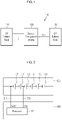
- FIG. 1 is a diagram showing a battery apparatus according to an embodiment.
- a battery apparatus 100 includes a high voltage (HV) battery pack 110, a low voltage (LV) battery pack 120, and a battery management system (BMS) 130.
- HV high voltage
- LV low voltage
- BMS battery management system
- the battery apparatus 100 has a structure that can be electrically connected to an external apparatus.
- the battery apparatus 100 When the external apparatus is a load, the battery apparatus 100 is discharged by operating as a power supply that supplies power to the load.
- the external apparatus 10 operating as the load may be, for example, an electronic device, a mobility apparatus, or an energy storage system (ESS).
- the mobility apparatus may be, for example, a vehicle such as an electric vehicle, a hybrid vehicle, or a smart mobility.
- the HV battery pack 110 outputs a relatively high voltage and supplies power to a large-capacity load of the external apparatus.
- the LV battery pack 120 outputs a relatively low voltage and supplies power to a low-capacity load of the external apparatus.
- the voltage supplied from the HV battery pack 110 is higher than the voltage supplied from the LV battery pack 120.
- the large-capacity load may be a load for driving the vehicle, including, for example, a motor of the vehicle.
- the low-capacity load of the external apparatus may be a load used to control the vehicle, for example, an electrical component.
- the HV battery pack 110 and the LV battery pack 120 each include a plurality of battery cells (not shown).
- the battery cell may be a rechargeable cell.
- Each battery pack 110 or 120 may include a battery module in which a predetermined number of battery cells are connected in series. In some embodiments, in each battery pack 110 or 120, a predetermined number of battery modules may be connected in series or in parallel to supply desired power.
- the HV battery pack 110 is connected to the battery management system 130 through wires (not shown).
- each of the plurality of battery cells of the HV battery pack 110 may be connected to the battery management system 130 through the wire.
- the battery management system 130 may include a processor 131.
- the processor 131 may collect and analyze various information about the battery cells to control charging and discharging of the battery cells, a cell balancing operation, a protection operation, and the like.
- the processor 131 may be, for example, a micro controller unit (MCU).
- the battery management system 130 may further include various monitoring circuits (not shown) such as cell voltage monitoring circuits.
- the battery management system 130 may collect and analyze various information about the battery cells of the LV battery pack 120 to control charging and discharging of the battery cells, a cell balancing operation, a protection operation, and the like.
- the battery apparatus 110 may further include a separate battery management system (not shown) for the LV battery pack 120.
- An operating device of the battery management system 130 may be operated by receiving an operating voltage.
- some battery cells of the LV battery pack 120 may supply the operating voltage Vcc for the battery management system 130.
- a DC/DC converter for lowering the voltage of the power supply, an LDO regulator, and components for voltage stabilization may not be used.
- the voltage of the HV battery pack 110 may be not provided as the operating voltage Vcc, and only the LV battery pack 120 may supply the operating voltage Vcc. Accordingly, the power supplied to the large-capacity load may not be affected by the supply of the operating voltage Vcc.
- FIG. 2 is a diagram for explaining supply of an operating voltage of a battery management system according to an embodiment.
- an LV battery pack 210 includes a plurality of battery cells connected in series. Although six battery cells C1, C2, C3, C4, C5, and C6 are shown in FIG. 2 for convenience of description, the number of battery cells included in the LV battery pack is not limited thereto.
- some adjacent battery cells C1 and C2 form one battery cell group to supply an operating voltage to a battery management system 220.
- the two battery cells C1 and C2 may supply the operating voltage.
- wires 211 and 212 are connected to a negative electrode of the first battery cell C1 and a positive electrode of the last battery cell C2, respectively.
- the wire 211 is connected to a terminal corresponding to a ground potential of the battery management system 220
- the wire 212 is connected to a terminal for supplying the operating voltage of the battery management system 220.
- the wire 211 may connected to the ground terminal of the processor 221 of the battery management system 220, i.e., a ground pin GND
- the wire 212 may be connected to an operating voltage supply terminal of the processor 221, i.e., an operating voltage supply pin Vcc.
- a sum (e.g., 5V) of voltages of the battery cells C1 and C2 included in the battery cell group may be supplied as the operating voltage of the battery management system 220.
- FIG. 3 and FIG. 4 are diagrams for explaining supply of an operating voltage of a battery management system according to another embodiment
- FIG. 5 is a diagram showing an example of a switching circuit shown in FIG. 3 .
- an LV battery pack 310 includes a plurality of battery cells connected in series. Although six battery cells C1, C2, C3, C4, C5, and C6 are shown in FIG. 3 for convenience of description, the number of battery cells included in the LV battery pack is not limited thereto.
- a plurality of battery cells of the LV battery pack 310 are grouped into a plurality of battery cell groups G1, G2, and G3, and each battery cell group Gi includes battery cells that can supply a voltage corresponding to the operating voltage of the battery management system 320.
- i is an integer from 1 to 3.
- each battery cell group Gi may include two adjacent battery cells. That is, one battery cell group G1 may include two battery cells C1 and C2, another battery cell group G2 may include two other battery cells C3 and C4, and yet another battery cell group G3 may include two other battery cells C5 and C6.
- wires 311 and 312 are connected to a negative electrode of the first battery cell C1 and a positive electrode of the last battery cell C2, respectively.
- wires 312 and 313 are connected to a negative electrode of the first battery cell C3 and a positive electrode of the last battery cell C4, respectively.
- the same wire 312 is connected to the positive electrode of the battery cell C2 and the negative electrode of the battery cell C3.
- a separate wire other than the wire 312 may be connected to the negative electrode of the first battery cell C3 of the battery cell group G2.
- wires 313 and 314 are connected to a negative electrode of the first battery cell C5 and a positive electrode of the last battery cell C6, respectively.
- the same wire 313 is connected to the positive electrode of the battery cell C4 and the negative electrode of the battery cell C5.
- a separate wire other than the wire 313 may be connected to the negative electrode of the first battery cell C5 of the battery cell group G3.
- the battery management system 320 includes a switching circuit 322.
- the switching circuit 322 is connected to the wires 311, 312, 313, and 314, and has a negative output terminal 323 and a positive output terminal 324.
- the negative output terminal 323 is connected to a ground terminal of an operating device of the battery management system 320
- the positive output terminal 324 is connected to an operating voltage supply terminal of the operating device of the battery management system 320. In some embodiments, as shown in FIG.
- the negative output terminal 323 may be connected to a ground terminal of a processor 321 of the battery management system 320, i.e., a ground pin GND, and the positive output terminal 324 may be connected to an operating voltage supply terminal of the processor 321, i.e., an operating voltage supply pin Vcc.
- the switching circuit 322 periodically switches connections among the wires 311, 312, 313, and 314, the negative output terminal 323, and the positive output terminal 324.
- the switching circuit 322 may connect the wire 311 to the negative output terminal 323 and the wire 312 to the positive output terminal 324 during a first period T1 so that the battery cell group G1 can supply the operating voltage.
- the switching circuit 322 may connect the wire 312 to the negative output terminal 323 and the wire 313 to the positive output terminal 324 during a second period T2 so that the battery cell group G2 can supply the operating voltage.
- the switching circuit 322 may connect the wire 313 to the negative output terminal 323 and the wire 314 to the positive output terminal 324 during a third period T3 so that the battery cell group G3 can supply the operating voltage.
- the switching circuit 322 may alternately select the plurality of battery cell groups G1, G2, and G3 and supply the operating voltage by repeating the first period T1, the second period T2, and the third period T3. Accordingly, it is possible to prevent an imbalance in battery cell voltage that may occur when the operating voltage is supplied only from a specific battery cell group.
- the switching circuit 322 may allow two battery cell groups to simultaneously supply the operating voltage when switching to another period. Accordingly, it is possible to ensure that there is no blank period in the supply of the operating voltage.
- durations of the first period T1, the second period T2, and the third period T3 may be set to be the same.
- the processor 321 of the battery management system 320 may control operations of the switching circuit 322.
- the switching circuit 322 may include a plurality of switches S1, S2, S3, S4, S5, and S6.
- the switch S1 is connected between the wire 311 and the negative output terminal 323, and the switch S2 is connected between the wire 312 and the positive output terminal 324.
- the switch S3 is connected between the wire 312 and the negative output terminal 323, and the switch S4 is connected between the wire 313 and the positive output terminal 324.
- the switch S5 is connected between the wire 313 and the negative output terminal 323, and the switch S6 is connected between the wire 314 and the positive output terminal 324.
- the battery management system may turn on the switches S1 and S2 to select the battery cell group G1, turn on the switches S3 and S4 to select the battery cell group G2, and turn on the switches S5 and S6 to select the battery cell group G3.
- FIG. 6 is a flowchart showing a voltage supply method according to another embodiment.
- a battery management system selects one battery cell group from among a plurality of battery cells of an LV battery pack at S610.
- the selected battery cell group supplies an operating voltage to an operating device of the battery management system at S620.
- the operating voltage is continuously supplied from the selected battery cell group at S620.
- the battery management system selects another battery cell group from the LV battery pack at S610. Accordingly, the newly selected battery cell group may supply the operating voltage to the operating device of the battery management system at S620.
- the battery management system may supply the operating voltage to the operating device of the battery management system while balancing battery cell voltages.
Landscapes
- Engineering & Computer Science (AREA)
- Manufacturing & Machinery (AREA)
- Chemical & Material Sciences (AREA)
- Chemical Kinetics & Catalysis (AREA)
- Electrochemistry (AREA)
- General Chemical & Material Sciences (AREA)
- Power Engineering (AREA)
- Microelectronics & Electronic Packaging (AREA)
- Charge And Discharge Circuits For Batteries Or The Like (AREA)
- Secondary Cells (AREA)
- Direct Current Feeding And Distribution (AREA)
Abstract
Description
- This application claims priority to and the benefit of
Korean Patent Application No. 10-2021-0002663 filed in the Korean Intellectual Property Office on January 8, 2021 - The described technology relates to a battery apparatus and a method of supplying a voltage.
- An electric vehicle or a hybrid vehicle is a vehicle that obtains power by driving a motor mainly using a battery as a power supply. The electric vehicles are being actively researched because they are alternatives that can solve pollution and energy problems of internal combustion vehicles. Rechargeable batteries are used in various external apparatuses other than the electric vehicles.
- The battery apparatus includes a battery pack and a battery management system for managing the battery pack. The battery management system monitors various information such as a voltage, a state of charge and a temperature of battery cells included in the battery and includes various circuits for monitoring the various information.
- Currently, a power source for supplying power to electronic components is used to supply power to the battery management system. However, since a voltage (e.g., 12V) supplied from the power supply for supplying the power to the electronic components is higher than an operating voltage (e.g., 5V) of the battery management system, a component for lowering the voltage of the power supply is required. When the voltage is lowered in this way, electromagnetic interference (EMI) may occur in a DC/DC (direct current to direct current) converter, power consumption may increase due to a low dropout (LDO) regulator, and additional components may be required for voltage stabilization.
- Some embodiments may provide a battery apparatus and a method of supplying a voltage capable of supplying an operating voltage of a battery management system without using a component for voltage drop.
- According to an embodiment, a battery apparatus including a first battery pack configured to provide a first voltage, a battery management system configured to manage the first battery pack, and a second battery pack configured to provide a second voltage lower than the first voltage may be provided. The second battery pack may include a plurality of battery cells, and the battery management system may select a battery cell group including a predetermined number of battery cells from among the plurality of battery cells of the second battery pack. The selected battery cell group may supply an operating voltage to an operating device of the battery management system.
- In some embodiments, a voltage of the first battery pack may not be provided as the operating voltage.
- In some embodiments, the operating voltage may correspond to a sum of voltages of the predetermined number of battery cells.
- In some embodiments, a wire connected to a negative electrode of a first battery cell among the predetermined number of battery cells may be connected to a ground terminal of the operating device, and a wire connected to a positive electrode of a last battery cell among the predetermined number of battery cells may be connected to an operating voltage supply terminal of the operating device.
- In some embodiments, the plurality of battery cells of the second battery pack may be grouped into a plurality of battery cell groups, and each of the plurality of battery cell groups may include battery cells corresponding to the predetermined number. The battery management system may select the battery cell group from among the plurality of battery cell groups.
- In some embodiments, the battery management system may alternately select one battery cell group from among the plurality of battery cell groups at a predetermined time interval.
- In some embodiments, the battery management system may further include a switching circuit configured to select the plurality of battery cell groups.
- In some embodiments, the plurality of battery cell groups may include a first battery cell group and a second battery cell group. In response to selecting the first battery cell group, the switching circuit may connect a first wire connected to a negative electrode of a first battery cell among the predetermined number of battery cells in the first battery cell group to a ground terminal of the operating device, and connect a second wire connected to a positive electrode of a last battery cell among the predetermined number of battery cells in the first battery cell group to an operating voltage supply terminal of the operating device. In response to selecting the second battery cell group, the switching circuit may connect a third wire connected to a negative electrode of a first battery cell among the predetermined number of battery cells in the second battery cell group to the ground terminal, and connect a fourth wire connected to a positive electrode of a last battery cell among the predetermined number of battery cells in the second battery cell group to the operating voltage supply terminal.
- In some embodiments, the switching circuit may include a first switch connected between the first wire and the ground terminal, a second switch connected between the second wire and the operating voltage supply terminal, a third switch connected between the third wire and the ground terminal, and a fourth switch connected between the fourth wire and the operating voltage supply terminal. The battery management system may select the first battery cell group by turning on the first switch and the second switch, and may select the second battery cell group by turning on the third switch and the fourth switch.
- In some embodiments, the operating device may include a processor.
- According to another embodiment, a method of supplying a voltage in a battery apparatus including a first battery pack configured to supply a first voltage, a second battery pack configured to supply a second voltage lower than the first voltage, and a battery management system configured to manage the first battery pack may be provided. The method may include selecting a first battery cell group including a predetermined number of battery cells from among a plurality of battery cells included in the second battery pack, and supplying an operating voltage to an operating device of the battery management system through the first battery cell group.
- In some embodiments, the method may further include selecting a second battery cell group including the predetermined number of other battery cells from among the plurality of battery cells in response to a predetermined time elapsing after selecting the first battery cell group, and supplying the operating voltage to the operating device of the battery management system through the second battery cell group.
- According to yet another embodiment, a battery apparatus including a battery pack including a plurality of battery cells and a battery management system may be provided. The battery management system may group the plurality of battery cells of the battery pack into a plurality of battery cell groups each including a predetermined number of battery cells, alternately select one battery cell group from among the plurality of battery cell groups, and providing an operating voltage to an operating device of the battery management system through the selected battery cell group.
- According to some embodiments, it is possible to supply the operating voltage of the battery management system without using a component for lowering the voltage of the power supply.
-
-
FIG. 1 is a diagram showing a battery apparatus according to an embodiment. -
FIG. 2 is a diagram for explaining supply of an operating voltage of a battery management system according to an embodiment. -
FIG. 3 and FIG. 4 are diagrams for explaining supply of an operating voltage of a battery management system according to another embodiment. -
FIG. 5 is a diagram showing an example of a switching circuit shown inFIG. 3 . -
FIG. 6 is a flowchart showing a voltage supply method according to another embodiment. - In the following detailed description, only certain embodiments have been shown and described, simply by way of illustration. As those skilled in the art would realize, the described embodiments may be modified in various different ways, all without departing from the spirit or scope of the present invention. Accordingly, the drawings and description are to be regarded as illustrative in nature and not restrictive. Like reference numerals designate like elements throughout the specification.
- When it is described that an element is "connected" to another element, it should be understood that the element may be directly connected to the other element or connected to the other element through a third element. On the other hand, when it is described that an element is "directly connected" to another element, it should be understood that the element is connected to the other element through no third element.
- As used herein, a singular form may be intended to include a plural form as well, unless the explicit expression such as "one" or "single" is used.
- In flowcharts described with reference to the drawings, the order of operations or steps may be changed, several operations or steps may be merged, a certain operation or step may be divided, and a specific operation or step may not be performed.
-
FIG. 1 is a diagram showing a battery apparatus according to an embodiment. - Referring to
FIG. 1 , abattery apparatus 100 includes a high voltage (HV)battery pack 110, a low voltage (LV)battery pack 120, and a battery management system (BMS) 130. - The
battery apparatus 100 has a structure that can be electrically connected to an external apparatus. When the external apparatus is a load, thebattery apparatus 100 is discharged by operating as a power supply that supplies power to the load. The external apparatus 10 operating as the load may be, for example, an electronic device, a mobility apparatus, or an energy storage system (ESS). The mobility apparatus may be, for example, a vehicle such as an electric vehicle, a hybrid vehicle, or a smart mobility. - The
HV battery pack 110 outputs a relatively high voltage and supplies power to a large-capacity load of the external apparatus. TheLV battery pack 120 outputs a relatively low voltage and supplies power to a low-capacity load of the external apparatus. The voltage supplied from theHV battery pack 110 is higher than the voltage supplied from theLV battery pack 120. In some embodiments, the large-capacity load may be a load for driving the vehicle, including, for example, a motor of the vehicle. In some embodiments, the low-capacity load of the external apparatus may be a load used to control the vehicle, for example, an electrical component. - The
HV battery pack 110 and theLV battery pack 120 each include a plurality of battery cells (not shown). In some embodiments, the battery cell may be a rechargeable cell. Eachbattery pack battery pack - The
HV battery pack 110 is connected to thebattery management system 130 through wires (not shown). For example, each of the plurality of battery cells of theHV battery pack 110 may be connected to thebattery management system 130 through the wire. Thebattery management system 130 may include a processor 131. The processor 131 may collect and analyze various information about the battery cells to control charging and discharging of the battery cells, a cell balancing operation, a protection operation, and the like. In some embodiments, the processor 131 may be, for example, a micro controller unit (MCU). In some embodiments, thebattery management system 130 may further include various monitoring circuits (not shown) such as cell voltage monitoring circuits. - In some embodiments, the
battery management system 130 may collect and analyze various information about the battery cells of theLV battery pack 120 to control charging and discharging of the battery cells, a cell balancing operation, a protection operation, and the like. - In some embodiments, the
battery apparatus 110 may further include a separate battery management system (not shown) for theLV battery pack 120. - An operating device of the
battery management system 130, for example, the processor 131 of thebattery management system 130 may be operated by receiving an operating voltage. To this end, some battery cells of theLV battery pack 120 may supply the operating voltage Vcc for thebattery management system 130. Accordingly, a DC/DC converter for lowering the voltage of the power supply, an LDO regulator, and components for voltage stabilization may not be used. In some embodiments, the voltage of theHV battery pack 110 may be not provided as the operating voltage Vcc, and only theLV battery pack 120 may supply the operating voltage Vcc. Accordingly, the power supplied to the large-capacity load may not be affected by the supply of the operating voltage Vcc. -
FIG. 2 is a diagram for explaining supply of an operating voltage of a battery management system according to an embodiment. - Referring to
FIG. 2 , anLV battery pack 210 includes a plurality of battery cells connected in series. Although six battery cells C1, C2, C3, C4, C5, and C6 are shown inFIG. 2 for convenience of description, the number of battery cells included in the LV battery pack is not limited thereto. - Among the plurality of battery cells of the
LV battery pack 210, some adjacent battery cells C1 and C2 form one battery cell group to supply an operating voltage to abattery management system 220. For example, when a voltage of each battery cell of theLV battery pack 210 is 2.5V and the operating voltage of thebattery management system 220 is 5V, the two battery cells C1 and C2 may supply the operating voltage. - In the battery cell group,
wires wire 211 is connected to a terminal corresponding to a ground potential of thebattery management system 220, and thewire 212 is connected to a terminal for supplying the operating voltage of thebattery management system 220. In some embodiments, as shown inFIG. 2 , thewire 211 may connected to the ground terminal of theprocessor 221 of thebattery management system 220, i.e., a ground pin GND, and thewire 212 may be connected to an operating voltage supply terminal of theprocessor 221, i.e., an operating voltage supply pin Vcc. - Accordingly, a sum (e.g., 5V) of voltages of the battery cells C1 and C2 included in the battery cell group may be supplied as the operating voltage of the
battery management system 220. -
FIG. 3 and FIG. 4 are diagrams for explaining supply of an operating voltage of a battery management system according to another embodiment, andFIG. 5 is a diagram showing an example of a switching circuit shown inFIG. 3 . - Referring to
FIG. 3 , anLV battery pack 310 includes a plurality of battery cells connected in series. Although six battery cells C1, C2, C3, C4, C5, and C6 are shown inFIG. 3 for convenience of description, the number of battery cells included in the LV battery pack is not limited thereto. - A plurality of battery cells of the
LV battery pack 310 are grouped into a plurality of battery cell groups G1, G2, and G3, and each battery cell group Gi includes battery cells that can supply a voltage corresponding to the operating voltage of thebattery management system 320. Here, i is an integer from 1 to 3. For example, when a voltage of each battery cell of theLV battery pack 210 is 2.5V and the operating voltage of thebattery management system 320 is 5V, each battery cell group Gi may include two adjacent battery cells. That is, one battery cell group G1 may include two battery cells C1 and C2, another battery cell group G2 may include two other battery cells C3 and C4, and yet another battery cell group G3 may include two other battery cells C5 and C6. - In the battery cell group G1,
wires wires same wire 312 is connected to the positive electrode of the battery cell C2 and the negative electrode of the battery cell C3. In some embodiments, a separate wire other than thewire 312 may be connected to the negative electrode of the first battery cell C3 of the battery cell group G2. Similarly, in the battery cell group G3,wires same wire 313 is connected to the positive electrode of the battery cell C4 and the negative electrode of the battery cell C5. In some embodiments, a separate wire other than thewire 313 may be connected to the negative electrode of the first battery cell C5 of the battery cell group G3. - The
battery management system 320 includes aswitching circuit 322. Theswitching circuit 322 is connected to thewires negative output terminal 323 and apositive output terminal 324. Thenegative output terminal 323 is connected to a ground terminal of an operating device of thebattery management system 320, and thepositive output terminal 324 is connected to an operating voltage supply terminal of the operating device of thebattery management system 320. In some embodiments, as shown inFIG. 3 , thenegative output terminal 323 may be connected to a ground terminal of aprocessor 321 of thebattery management system 320, i.e., a ground pin GND, and thepositive output terminal 324 may be connected to an operating voltage supply terminal of theprocessor 321, i.e., an operating voltage supply pin Vcc. - The
switching circuit 322 periodically switches connections among thewires negative output terminal 323, and thepositive output terminal 324. In some embodiments, as shown inFIG. 4 , theswitching circuit 322 may connect thewire 311 to thenegative output terminal 323 and thewire 312 to thepositive output terminal 324 during a first period T1 so that the battery cell group G1 can supply the operating voltage. After the first period T1, theswitching circuit 322 may connect thewire 312 to thenegative output terminal 323 and thewire 313 to thepositive output terminal 324 during a second period T2 so that the battery cell group G2 can supply the operating voltage. After the second period T2, theswitching circuit 322 may connect thewire 313 to thenegative output terminal 323 and thewire 314 to thepositive output terminal 324 during a third period T3 so that the battery cell group G3 can supply the operating voltage. Theswitching circuit 322 may alternately select the plurality of battery cell groups G1, G2, and G3 and supply the operating voltage by repeating the first period T1, the second period T2, and the third period T3. Accordingly, it is possible to prevent an imbalance in battery cell voltage that may occur when the operating voltage is supplied only from a specific battery cell group. - In some embodiments, the
switching circuit 322 may allow two battery cell groups to simultaneously supply the operating voltage when switching to another period. Accordingly, it is possible to ensure that there is no blank period in the supply of the operating voltage. - In some embodiments, durations of the first period T1, the second period T2, and the third period T3 may be set to be the same.
- In some embodiments, the
processor 321 of thebattery management system 320 may control operations of theswitching circuit 322. - In some embodiments, as shown in
FIG. 5 , theswitching circuit 322 may include a plurality of switches S1, S2, S3, S4, S5, and S6. The switch S1 is connected between thewire 311 and thenegative output terminal 323, and the switch S2 is connected between thewire 312 and thepositive output terminal 324. The switch S3 is connected between thewire 312 and thenegative output terminal 323, and the switch S4 is connected between thewire 313 and thepositive output terminal 324. The switch S5 is connected between thewire 313 and thenegative output terminal 323, and the switch S6 is connected between thewire 314 and thepositive output terminal 324. Accordingly, the battery management system may turn on the switches S1 and S2 to select the battery cell group G1, turn on the switches S3 and S4 to select the battery cell group G2, and turn on the switches S5 and S6 to select the battery cell group G3. -
FIG. 6 is a flowchart showing a voltage supply method according to another embodiment. - Referring to
FIG. 6 , a battery management system selects one battery cell group from among a plurality of battery cells of an LV battery pack at S610. The selected battery cell group supplies an operating voltage to an operating device of the battery management system at S620. - If a predetermined time has not elapsed after selecting one battery cell group at S630, the operating voltage is continuously supplied from the selected battery cell group at S620. When a predetermined time has elapsed after selecting one battery cell group, the battery management system selects another battery cell group from the LV battery pack at S610. Accordingly, the newly selected battery cell group may supply the operating voltage to the operating device of the battery management system at S620.
- By repeating the processes of S610, S620, and S630, the battery management system may supply the operating voltage to the operating device of the battery management system while balancing battery cell voltages.
- While this invention has been described in connection with what is presently considered to be practical embodiments, it is to be understood that the invention is not limited to the disclosed embodiments. On the contrary, it is intended to cover various modifications and equivalent arrangements included within the spirit and scope of the appended claims.
Claims (15)
- A battery apparatus comprising:a first battery pack configured to provide a first voltage;a battery management system configured to manage the first battery pack; anda second battery pack configured to provide a second voltage lower than the first voltage and including a plurality of battery cells,wherein the battery management system is configured to select a battery cell group including a predetermined number of battery cells from among the plurality of battery cells of the second battery pack, andwherein the selected battery cell group supplies an operating voltage to an operating device of the battery management system.
- The battery apparatus of claim 1, wherein a voltage of the first battery pack is not provided as the operating voltage.
- The battery apparatus of claim 1, wherein the operating voltage corresponds to a sum of voltages of the predetermined number of battery cells.
- The battery apparatus of claim 1, wherein a wire connected to a negative electrode of a first battery cell among the predetermined number of battery cells is connected to a ground terminal of the operating device, and a wire connected to a positive electrode of a last battery cell among the predetermined number of battery cells is connected to an operating voltage supply terminal of the operating device.
- The battery apparatus of claim 1, wherein the plurality of battery cells of the second battery pack is grouped into a plurality of battery cell groups, and each of the plurality of battery cell groups includes battery cells corresponding to the predetermined number, and
wherein the battery management system is configured to select the battery cell group from among the plurality of battery cell groups. - The battery apparatus of claim 5, wherein the battery management system is configured to alternately select one battery cell group from among the plurality of battery cell groups at a predetermined time interval.
- The battery apparatus of claim 5, wherein the battery management system further includes a switching circuit configured to select the plurality of battery cell groups.
- The battery apparatus of claim 7, wherein the plurality of battery cell groups includes a first battery cell group and a second battery cell group,wherein the switching circuit is configured to, in response to selecting the first battery cell group, connect a first wire connected to a negative electrode of a first battery cell among the predetermined number of battery cells in the first battery cell group to a ground terminal of the operating device, and connect a second wire connected to a positive electrode of a last battery cell among the predetermined number of battery cells in the first battery cell group to an operating voltage supply terminal of the operating device, andwherein the switching circuit is configured to, in response to selecting the second battery cell group, connect a third wire connected to a negative electrode of a first battery cell among the predetermined number of battery cells in the second battery cell group to the ground terminal, and connect a fourth wire connected to a positive electrode of a last battery cell among the predetermined number of battery cells in the second battery cell group to the operating voltage supply terminal.
- The battery apparatus of claim 8, wherein the switching circuit includes:a first switch connected between the first wire and the ground terminal;a second switch connected between the second wire and the operating voltage supply terminal;a third switch connected between the third wire and the ground terminal; anda fourth switch connected between the fourth wire and the operating voltage supply terminal, andwherein the battery management system is configured to select the first battery cell group by turning on the first switch and the second switch, and select the second battery cell group by turning on the third switch and the fourth switch.
- The battery apparatus of claim 1, wherein the operating device includes a processor.
- A method of supplying a voltage in a battery apparatus including a first battery pack configured to supply a first voltage, a second battery pack configured to supply a second voltage lower than the first voltage, and a battery management system configured to manage the first battery pack, the method comprising:selecting a first battery cell group including a predetermined number of battery cells from among a plurality of battery cells included in the second battery pack; andsupplying an operating voltage to an operating device of the battery management system through the first battery cell group.
- The method of claim 11, wherein a voltage of the first battery pack is not provided as the operating voltage.
- The method of claim 11, further comprising:selecting a second battery cell group including the predetermined number of other battery cells from among the plurality of battery cells in response to a predetermined time elapsing after selecting the first battery cell group; andsupplying the operating voltage to the operating device of the battery management system through the second battery cell group.
- The method of claim 11, wherein the operating voltage corresponds to a sum of voltages of the predetermined number of battery cells.
- A battery apparatus comprising:a battery pack including a plurality of battery cells; anda battery management system configured to:group the plurality of battery cells of the battery pack into a plurality of battery cell groups each including a predetermined number of battery cells;alternately select one battery cell group from among the plurality of battery cell groups; andproviding an operating voltage to an operating device of the battery management system through the selected battery cell group.
Applications Claiming Priority (2)
| Application Number | Priority Date | Filing Date | Title |
|---|---|---|---|
| KR1020210002663A KR20220100332A (en) | 2021-01-08 | 2021-01-08 | Battery apparatus and method of supplying voltage |
| PCT/KR2021/019911 WO2022149780A1 (en) | 2021-01-08 | 2021-12-27 | Battery device and voltage supply method |
Publications (3)
| Publication Number | Publication Date |
|---|---|
| EP4080720A1 true EP4080720A1 (en) | 2022-10-26 |
| EP4080720A4 EP4080720A4 (en) | 2023-08-23 |
| EP4080720B1 EP4080720B1 (en) | 2025-01-29 |
Family
ID=82357226
Family Applications (1)
| Application Number | Title | Priority Date | Filing Date |
|---|---|---|---|
| EP21917941.3A Active EP4080720B1 (en) | 2021-01-08 | 2021-12-27 | Battery device and voltage supply method |
Country Status (8)
| Country | Link |
|---|---|
| US (1) | US20230246459A1 (en) |
| EP (1) | EP4080720B1 (en) |
| JP (1) | JP7459439B2 (en) |
| KR (1) | KR20220100332A (en) |
| CN (1) | CN115053427A (en) |
| ES (1) | ES3014081T3 (en) |
| HU (1) | HUE070133T2 (en) |
| WO (1) | WO2022149780A1 (en) |
Cited By (1)
| Publication number | Priority date | Publication date | Assignee | Title |
|---|---|---|---|---|
| WO2024195206A1 (en) * | 2023-03-20 | 2024-09-26 | パナソニックIpマネジメント株式会社 | Power supply device and power supply system |
Families Citing this family (1)
| Publication number | Priority date | Publication date | Assignee | Title |
|---|---|---|---|---|
| KR20240104578A (en) * | 2022-12-28 | 2024-07-05 | 주식회사 엘지에너지솔루션 | Battery system and method for controlling connection between battery packs using the same |
Family Cites Families (123)
| Publication number | Priority date | Publication date | Assignee | Title |
|---|---|---|---|---|
| JP4238095B2 (en) * | 2003-08-29 | 2009-03-11 | 矢崎総業株式会社 | Voltage detection device for battery pack |
| US7091697B2 (en) * | 2003-11-04 | 2006-08-15 | Sony Corporation | System and method for efficiently implementing a battery controller for an electronic device |
| JP2005165545A (en) * | 2003-12-01 | 2005-06-23 | Sony Corp | Electronic equipment and battery pack |
| KR100991084B1 (en) * | 2005-12-15 | 2010-10-29 | 주식회사 엘지화학 | Multi battery pack system and control method thereof, and battery pack using same |
| KR100649570B1 (en) * | 2005-12-19 | 2006-11-27 | 삼성에스디아이 주식회사 | Battery Management Systems and Methods and Battery Systems |
| US7839121B2 (en) * | 2006-03-20 | 2010-11-23 | Lg Electronics Inc. | Apparatus and method for managing power of battery packs in a portable device |
| KR100908716B1 (en) * | 2007-03-02 | 2009-07-22 | 삼성에스디아이 주식회사 | Battery Management System and Its Driving Method |
| JP5250230B2 (en) * | 2007-09-28 | 2013-07-31 | 株式会社日立製作所 | Power supply system for vehicle and integrated circuit for battery cell control |
| KR101107115B1 (en) * | 2008-12-01 | 2012-01-30 | 삼성에스디아이 주식회사 | Battery Management System and Battery Care Methods |
| JP2010220279A (en) * | 2009-03-13 | 2010-09-30 | Omron Corp | Power supply controller and method |
| US8493028B2 (en) * | 2009-04-03 | 2013-07-23 | Marvell World Trade Ltd. | Power management circuit for rechargeable battery stack |
| JP5722875B2 (en) * | 2009-04-10 | 2015-05-27 | ザ リージェンツ オブ ザ ユニバーシティ オブ ミシガン | Dynamically reconfigurable structure for large battery systems |
| US8823323B2 (en) * | 2009-04-16 | 2014-09-02 | Valence Technology, Inc. | Batteries, battery systems, battery submodules, battery operational methods, battery system operational methods, battery charging methods, and battery system charging methods |
| JP5468846B2 (en) * | 2009-08-25 | 2014-04-09 | 矢崎総業株式会社 | Multi-battery battery status monitoring unit |
| JP5503924B2 (en) * | 2009-08-27 | 2014-05-28 | 矢崎総業株式会社 | Multi-battery battery status monitoring unit |
| US8339100B2 (en) * | 2009-09-29 | 2012-12-25 | O2Micro Inc | Systems and methods for cell balancing |
| JP5481146B2 (en) * | 2009-09-30 | 2014-04-23 | 株式会社東芝 | Battery management device, secondary battery device and vehicle |
| EP2507891B1 (en) * | 2009-12-04 | 2018-03-28 | A123 Systems LLC | Battery with integrated power management system and scalable battery cutoff component |
| TWI502851B (en) * | 2010-02-09 | 2015-10-01 | 新德科技股份有限公司 | Lithium battery module |
| JP4602471B1 (en) * | 2010-04-14 | 2010-12-22 | 和征 榊原 | Battery pack and battery pack system |
| KR101184752B1 (en) * | 2010-06-03 | 2012-09-20 | 정윤이 | Battery package and charging method of battery package |
| KR101146378B1 (en) * | 2010-06-09 | 2012-05-17 | 삼성에스디아이 주식회사 | Charging battery pack and system thererwith |
| US8723481B2 (en) * | 2010-06-25 | 2014-05-13 | O2Micro, Inc. | Battery pack with balancing management |
| CN102299529B (en) * | 2010-06-25 | 2014-04-02 | 凹凸电子(武汉)有限公司 | Battery pack management system, electric vehicle and battery pack management method |
| KR101097272B1 (en) * | 2010-07-27 | 2011-12-21 | 삼성에스디아이 주식회사 | Battery pack and electric vehicle having same |
| US20120032513A1 (en) * | 2010-08-06 | 2012-02-09 | Energy Pass, Inc. | Battery management circuit, battery module and battery management method |
| JP5611727B2 (en) * | 2010-08-27 | 2014-10-22 | 三洋電機株式会社 | Power supply |
| JPWO2012049963A1 (en) * | 2010-10-15 | 2014-02-24 | 三洋電機株式会社 | Power supply system including storage battery |
| US8089249B2 (en) * | 2010-11-08 | 2012-01-03 | O2Micro, Inc. | Battery management systems and methods |
| JP5645679B2 (en) * | 2011-01-19 | 2014-12-24 | オムロンオートモーティブエレクトロニクス株式会社 | Voltage converter |
| US9331497B2 (en) * | 2011-03-05 | 2016-05-03 | Powin Energy Corporation | Electrical energy storage unit and control system and applications thereof |
| US9847654B2 (en) * | 2011-03-05 | 2017-12-19 | Powin Energy Corporation | Battery energy storage system and control system and applications thereof |
| US10536007B2 (en) * | 2011-03-05 | 2020-01-14 | Powin Energy Corporation | Battery energy storage system and control system and applications thereof |
| CA2830320A1 (en) * | 2011-03-17 | 2012-09-20 | Ev Chip Energy Ltd. | Battery pack system |
| US9340122B2 (en) * | 2011-05-31 | 2016-05-17 | Hitachi Automotive Systems, Ltd. | Battery system monitoring apparatus |
| JP2012253951A (en) * | 2011-06-03 | 2012-12-20 | Sony Corp | Power supply apparatus, charging method, rechargeable battery module, and charging apparatus |
| KR101856663B1 (en) * | 2011-06-03 | 2018-05-10 | 에스케이이노베이션 주식회사 | Secondary battery sub Unit, Secondary battery management system and Method for exchanging information in multi-pack parallel structure using the same |
| US20120319657A1 (en) * | 2011-06-16 | 2012-12-20 | O2 Micro USA | Battery management system |
| JP5339492B2 (en) * | 2011-07-15 | 2013-11-13 | 日本電気株式会社 | Power storage device |
| US9746525B2 (en) * | 2011-09-08 | 2017-08-29 | Hitachi Automotive Systems, Ltd. | Battery system monitoring device |
| US9018906B2 (en) * | 2011-09-09 | 2015-04-28 | Samsung Sdi Co., Ltd. | Battery pack |
| KR20130046234A (en) * | 2011-10-27 | 2013-05-07 | 삼성에스디아이 주식회사 | A battery pack and method for controlling the battery pack |
| JP5798887B2 (en) * | 2011-10-31 | 2015-10-21 | 株式会社日立製作所 | Power storage system |
| KR101872472B1 (en) * | 2011-11-04 | 2018-06-29 | 삼성에스디아이 주식회사 | Battery Pack, Battery protection circuit, and battery system |
| KR20130049880A (en) * | 2011-11-07 | 2013-05-15 | 삼성에스디아이 주식회사 | A battery pack and method for controlling the battery pack |
| KR20130091951A (en) * | 2012-02-09 | 2013-08-20 | 삼성에스디아이 주식회사 | Battery pack, controlling method of the same, and power storage system including the battery pack |
| US9496749B2 (en) * | 2012-03-23 | 2016-11-15 | Hitachi Automotive Systems, Ltd. | Storage battery control device and electrical storage device |
| US9231440B2 (en) * | 2012-04-18 | 2016-01-05 | Samsung Sdi Co., Ltd. | Power supply apparatus and controlling method of the same |
| US10297855B2 (en) * | 2012-05-29 | 2019-05-21 | Nutech Ventures | Rechargeable multi-cell battery |
| EP2696465B1 (en) * | 2012-08-09 | 2016-12-21 | Samsung SDI Co., Ltd. | Battery management system and cell balancing method |
| JP6081320B2 (en) * | 2012-09-05 | 2017-02-15 | 株式会社東芝 | Power supply apparatus, battery pack control method and control program |
| US9318910B2 (en) * | 2012-09-06 | 2016-04-19 | Samsung Sdi Co., Ltd. | Cell balancing circuit and cell balancing method using the same |
| KR101973054B1 (en) * | 2012-10-16 | 2019-04-26 | 삼성에스디아이 주식회사 | Battery pack and method of controlling the battery pack |
| KR101477272B1 (en) * | 2012-11-09 | 2015-01-06 | 주식회사 엘지화학 | Apparatus and method for balancing work of secondary battery cell's changing capacity |
| KR101630002B1 (en) * | 2012-11-12 | 2016-06-21 | 삼성에스디아이 주식회사 | Energy storage system |
| KR101909275B1 (en) * | 2012-11-14 | 2018-10-17 | 현대모비스 주식회사 | Apparatus and Method for Battery Charge |
| CN103972930A (en) * | 2013-01-24 | 2014-08-06 | 凹凸电子(武汉)有限公司 | Battery management system, method for controlling charging of battery pack and battery pack |
| JP6119516B2 (en) * | 2013-09-02 | 2017-04-26 | ソニー株式会社 | Battery pack and electric vehicle |
| US10056653B2 (en) * | 2013-12-10 | 2018-08-21 | Sanyo Electric Co., Ltd. | Battery management device and power supply device |
| KR20150081731A (en) * | 2014-01-06 | 2015-07-15 | 삼성에스디아이 주식회사 | Battery pack, energy storage system including the battery pack, and method of operating the battery pack |
| KR20150081696A (en) * | 2014-01-06 | 2015-07-15 | 삼성에스디아이 주식회사 | Battery charging device and battery charging method |
| DE102014201346A1 (en) * | 2014-01-27 | 2015-07-30 | Robert Bosch Gmbh | board network |
| JP6479320B2 (en) * | 2014-02-25 | 2019-03-06 | ラピスセミコンダクタ株式会社 | Battery monitoring system and battery monitoring chip |
| JP6725201B2 (en) * | 2014-07-24 | 2020-07-15 | 矢崎総業株式会社 | Charge leveling device and power supply system |
| KR102257902B1 (en) * | 2014-07-29 | 2021-05-28 | 삼성전자주식회사 | Battery pack prividing different kind power source and charging method thereof |
| JPWO2016021136A1 (en) * | 2014-08-05 | 2017-05-25 | パナソニックIpマネジメント株式会社 | In-vehicle power storage system |
| KR101587358B1 (en) * | 2014-09-02 | 2016-02-02 | 엘에스산전 주식회사 | A hybrid vehicle |
| US10263436B2 (en) * | 2014-10-20 | 2019-04-16 | Powin Energy Corporation | Electrical energy storage unit and control system and applications thereof |
| EP3215862B1 (en) * | 2014-11-04 | 2021-01-06 | CPS Technology Holdings LLC | Scalable modular design of 48-volt li-ion battery management system |
| US20160149421A1 (en) * | 2014-11-24 | 2016-05-26 | Southwest Electronic Energy Corporation | Low voltage charging and balancing of a high voltage, series-connected string of battery modules |
| KR20160063757A (en) * | 2014-11-27 | 2016-06-07 | 삼성에스디아이 주식회사 | Battery charging method and battery pack using the method |
| KR102381085B1 (en) * | 2015-02-27 | 2022-04-01 | 삼성전자주식회사 | Dc-dc converter, charging integrated circuit and electronic device having the same and battery charging method thereof |
| US9859721B2 (en) * | 2015-03-16 | 2018-01-02 | Kabushiki Kaisha Toshiba | Storage battery management device, method, and computer program product |
| JP6403897B2 (en) * | 2015-09-11 | 2018-10-10 | 日立オートモティブシステムズ株式会社 | Battery management device |
| CN107251363B (en) * | 2015-12-31 | 2020-09-29 | 深圳市大疆创新科技有限公司 | Method and system for balancing battery assemblies |
| US20170217318A1 (en) * | 2016-01-29 | 2017-08-03 | Faraday&Future Inc. | Battery pack configuration |
| KR101667913B1 (en) * | 2016-03-25 | 2016-10-20 | (주)아이비티 | Apparatus and Method For Equalizing Charge of a Battery Pack |
| JP6767769B2 (en) * | 2016-04-27 | 2020-10-14 | ラピスセミコンダクタ株式会社 | Semiconductor devices, battery monitoring systems, and detection methods |
| US10608291B2 (en) * | 2016-05-20 | 2020-03-31 | Spiers New Technologies, Inc. | Battery pack having a supplemental power supply |
| JP6761172B2 (en) * | 2016-08-12 | 2020-09-23 | 株式会社今仙電機製作所 | Vehicle power supply |
| US10615465B2 (en) * | 2016-09-23 | 2020-04-07 | Artisan Vehicle Systems Inc. | Battery management system |
| CN209488195U (en) * | 2016-10-12 | 2019-10-11 | Oppo广东移动通信有限公司 | Mobile terminal |
| EP3529874B1 (en) * | 2016-10-18 | 2021-12-22 | Nerve Smart Systems ApS | Charging station for charging electrical vehicles |
| US10377262B2 (en) * | 2016-12-06 | 2019-08-13 | National Chung Shan Institute Of Science And Technology | Range extending apparatus for electric vehicle and control method thereof |
| KR102319241B1 (en) * | 2017-01-03 | 2021-10-28 | 삼성에스디아이 주식회사 | Voltage detecting ic and battery management system including the same |
| KR102308656B1 (en) * | 2017-01-24 | 2021-10-01 | 삼성에스디아이 주식회사 | Battery pack, management method of the same, and vehicle comprisin the same |
| US11990591B2 (en) * | 2017-02-08 | 2024-05-21 | Litech Laboratories, Inc. | Method for monitoring series-connected battery cells |
| JP6863795B2 (en) * | 2017-03-30 | 2021-04-21 | ビークルエナジージャパン株式会社 | Battery energy storage system, battery management system and control method |
| TWI627808B (en) * | 2017-04-28 | 2018-06-21 | 廣達電腦股份有限公司 | Battery device and battery protection method |
| KR102173777B1 (en) * | 2017-07-25 | 2020-11-03 | 주식회사 엘지화학 | Master battery management unit and a battery pack including the same |
| KR102173778B1 (en) * | 2017-07-25 | 2020-11-03 | 주식회사 엘지화학 | Battery management unit and a battery pack including the same |
| CN111095719B (en) * | 2017-09-12 | 2023-12-01 | 株式会社东芝 | battery device |
| US11063445B2 (en) * | 2017-12-05 | 2021-07-13 | Green Cubes Technology, Llc | Multi-cell battery management device |
| US10833511B2 (en) * | 2017-12-07 | 2020-11-10 | National Chung Shan Institute Of Science And Technology | Battery cell management and balance circuit, method, and battery system |
| US10807487B2 (en) * | 2017-12-11 | 2020-10-20 | National Chung Shan Institute Of Science And Technology | Battery management and balance circuit, battery system and method of charging the battery system |
| DE102017222557B4 (en) * | 2017-12-13 | 2024-10-17 | Vitesco Technologies GmbH | Multi-voltage battery device and on-board network for a motor vehicle |
| KR102525676B1 (en) * | 2018-02-20 | 2023-04-24 | 에스케이온 주식회사 | Battery management system |
| KR102338938B1 (en) * | 2018-05-03 | 2021-12-10 | 주식회사 엘지에너지솔루션 | Battery management apparatus, and energy storage system including the same |
| CN112352341B (en) * | 2018-06-27 | 2024-06-11 | 松下知识产权经营株式会社 | Battery systems, battery management devices |
| CA3107893C (en) * | 2018-08-01 | 2023-09-26 | Nanjing Chervon Industry Co., Ltd. | Riding lawn mower, and current-limiting protection method for same |
| JP2020031471A (en) * | 2018-08-21 | 2020-02-27 | スズキ株式会社 | In-vehicle power supply |
| KR20200024405A (en) * | 2018-08-28 | 2020-03-09 | 삼성전자주식회사 | Battery management apparatus, battery module, and battery pack |
| TW202013853A (en) * | 2018-09-26 | 2020-04-01 | 宏碁股份有限公司 | Battery management method and power supply system |
| JP7134058B2 (en) * | 2018-10-12 | 2022-09-09 | 株式会社マキタ | Power supply and power supply system |
| KR102443667B1 (en) * | 2018-10-26 | 2022-09-14 | 주식회사 엘지에너지솔루션 | balancing apparatus, and battery management system and battery pack including the same |
| CN113574713A (en) * | 2019-03-15 | 2021-10-29 | 日本汽车能源株式会社 | Battery system |
| JP2020178486A (en) * | 2019-04-19 | 2020-10-29 | 株式会社デンソー | Load drive |
| KR102876299B1 (en) * | 2019-08-20 | 2025-10-23 | 주식회사 엘지에너지솔루션 | Battery system and operating method thereof |
| KR102679823B1 (en) * | 2019-09-06 | 2024-07-03 | 주식회사 엘지에너지솔루션 | Battery system and controlling method of the same |
| WO2021053721A1 (en) * | 2019-09-17 | 2021-03-25 | 株式会社 東芝 | Storage battery device |
| KR102688137B1 (en) * | 2019-09-23 | 2024-07-24 | 주식회사 엘지에너지솔루션 | Battery management system, battery management method, battery pack and electric vehicle |
| JP7107495B2 (en) * | 2019-10-22 | 2022-07-27 | エルジー エナジー ソリューション リミテッド | Apparatus and method for balancing battery packs connected in parallel |
| US11349314B2 (en) * | 2019-11-06 | 2022-05-31 | GM Global Technology Operations LLC | Distributed battery power estimation with weaker cell monitoring |
| KR102796270B1 (en) * | 2020-02-05 | 2025-04-24 | 주식회사 유비파이 | Charging management system and method for batteries |
| IL273496A (en) * | 2020-03-22 | 2021-09-30 | Irp Nexus Group Ltd | Battery management system (bms) and application |
| WO2021243550A1 (en) * | 2020-06-02 | 2021-12-09 | Inventus Power, Inc. | Large-format battery management system |
| EP4175011A4 (en) * | 2020-06-26 | 2024-05-15 | Panasonic Intellectual Property Management Co., Ltd. | MANAGEMENT DEVICE AND POWER SUPPLY SYSTEM |
| WO2022019664A1 (en) * | 2020-07-21 | 2022-01-27 | 주식회사 엘지에너지솔루션 | Device and method for controlling output of parallel multi-pack module |
| KR20220031362A (en) * | 2020-09-04 | 2022-03-11 | 삼성에스디아이 주식회사 | Charging system and charger for reducing inrush current |
| US12119683B2 (en) * | 2020-10-23 | 2024-10-15 | Denso Corporation | Battery management device and battery device |
| CN116568554A (en) * | 2020-12-10 | 2023-08-08 | 苹果公司 | battery system |
| FR3118311B1 (en) * | 2020-12-23 | 2023-06-02 | Verkor | Energy storage unit comprising a battery module and method for managing such an energy storage unit |
| KR20220093601A (en) * | 2020-12-28 | 2022-07-05 | 주식회사 엘지에너지솔루션 | Method for assigning communication id and battery pack providing the same |
-
2021
- 2021-01-08 KR KR1020210002663A patent/KR20220100332A/en active Pending
- 2021-12-27 ES ES21917941T patent/ES3014081T3/en active Active
- 2021-12-27 US US17/789,583 patent/US20230246459A1/en active Pending
- 2021-12-27 JP JP2022547983A patent/JP7459439B2/en active Active
- 2021-12-27 HU HUE21917941A patent/HUE070133T2/en unknown
- 2021-12-27 WO PCT/KR2021/019911 patent/WO2022149780A1/en not_active Ceased
- 2021-12-27 CN CN202180008148.8A patent/CN115053427A/en active Pending
- 2021-12-27 EP EP21917941.3A patent/EP4080720B1/en active Active
Cited By (1)
| Publication number | Priority date | Publication date | Assignee | Title |
|---|---|---|---|---|
| WO2024195206A1 (en) * | 2023-03-20 | 2024-09-26 | パナソニックIpマネジメント株式会社 | Power supply device and power supply system |
Also Published As
| Publication number | Publication date |
|---|---|
| US20230246459A1 (en) | 2023-08-03 |
| WO2022149780A1 (en) | 2022-07-14 |
| HUE070133T2 (en) | 2025-05-28 |
| CN115053427A (en) | 2022-09-13 |
| KR20220100332A (en) | 2022-07-15 |
| EP4080720A4 (en) | 2023-08-23 |
| ES3014081T3 (en) | 2025-04-16 |
| JP2023514154A (en) | 2023-04-05 |
| EP4080720B1 (en) | 2025-01-29 |
| JP7459439B2 (en) | 2024-04-02 |
Similar Documents
| Publication | Publication Date | Title |
|---|---|---|
| US11247582B2 (en) | Control electronics for a battery system, method for power supplying control electronics for a battery system, battery system and vehicle | |
| EP3576241B1 (en) | Battery system | |
| US8193761B1 (en) | Hybrid power source | |
| EP2075892B1 (en) | Cell balancing systems with multiple controllers | |
| US11084397B2 (en) | Power supply system for vehicle with multiple operating voltages | |
| EP3722137B1 (en) | Control electronics for a battery system, method for power supplying control electronics for a battery system, battery system and vehicle | |
| EP3620321B1 (en) | Power supply system | |
| KR20150013302A (en) | Charge balancing in a battery | |
| EP4080720B1 (en) | Battery device and voltage supply method | |
| EP4080230A1 (en) | Battery apparatus and method for measuring cell voltage | |
| US20250392139A1 (en) | Cell balancing apparatus, battery apparatus including the same, and cell balancing method | |
| KR102876314B1 (en) | BATTERY APPARATUS and method for selecting battery pack | |
| KR20200143641A (en) | Control system for battery system, battery system and vehicle including the same | |
| US11329564B2 (en) | Control system for a battery system | |
| EP3337002B1 (en) | Battery system and control unit for a battery system | |
| KR102796089B1 (en) | Battery management system and balancing method | |
| EP3812205B1 (en) | Power supply system | |
| EP4186746A1 (en) | Battery system and method for operating the same | |
| KR20260063137A (en) | Battery management system, battery apparatus and balancing method | |
| Thiyagarajan et al. | Monitoring Stack Of Batteries For EV Through Controller Area Network Gateway | |
| CN119864520A (en) | Battery and vehicle | |
| KR20230018644A (en) | Battery apparatus, battery management system and balancing method | |
| CN116207808A (en) | Battery system, method of operating the same, vehicle and stationary energy storage system | |
| CN111114387A (en) | Method for equalizing the state of charge of a plurality of electrochemical energy stores that can be connected in parallel | |
| KR20220167594A (en) | Battery apparatus and method of controlling contactor |
Legal Events
| Date | Code | Title | Description |
|---|---|---|---|
| STAA | Information on the status of an ep patent application or granted ep patent |
Free format text: STATUS: THE INTERNATIONAL PUBLICATION HAS BEEN MADE |
|
| PUAI | Public reference made under article 153(3) epc to a published international application that has entered the european phase |
Free format text: ORIGINAL CODE: 0009012 |
|
| STAA | Information on the status of an ep patent application or granted ep patent |
Free format text: STATUS: REQUEST FOR EXAMINATION WAS MADE |
|
| 17P | Request for examination filed |
Effective date: 20220718 |
|
| AK | Designated contracting states |
Kind code of ref document: A1 Designated state(s): AL AT BE BG CH CY CZ DE DK EE ES FI FR GB GR HR HU IE IS IT LI LT LU LV MC MK MT NL NO PL PT RO RS SE SI SK SM TR |
|
| A4 | Supplementary search report drawn up and despatched |
Effective date: 20230721 |
|
| RIC1 | Information provided on ipc code assigned before grant |
Ipc: H01M 10/42 20060101ALI20230717BHEP Ipc: H02J 7/00 20060101AFI20230717BHEP |
|
| DAV | Request for validation of the european patent (deleted) | ||
| DAX | Request for extension of the european patent (deleted) | ||
| GRAP | Despatch of communication of intention to grant a patent |
Free format text: ORIGINAL CODE: EPIDOSNIGR1 |
|
| STAA | Information on the status of an ep patent application or granted ep patent |
Free format text: STATUS: GRANT OF PATENT IS INTENDED |
|
| INTG | Intention to grant announced |
Effective date: 20240620 |
|
| P01 | Opt-out of the competence of the unified patent court (upc) registered |
Free format text: CASE NUMBER: APP_39356/2024 Effective date: 20240702 |
|
| GRAS | Grant fee paid |
Free format text: ORIGINAL CODE: EPIDOSNIGR3 |
|
| GRAJ | Information related to disapproval of communication of intention to grant by the applicant or resumption of examination proceedings by the epo deleted |
Free format text: ORIGINAL CODE: EPIDOSDIGR1 |
|
| GRAL | Information related to payment of fee for publishing/printing deleted |
Free format text: ORIGINAL CODE: EPIDOSDIGR3 |
|
| STAA | Information on the status of an ep patent application or granted ep patent |
Free format text: STATUS: REQUEST FOR EXAMINATION WAS MADE |
|
| GRAP | Despatch of communication of intention to grant a patent |
Free format text: ORIGINAL CODE: EPIDOSNIGR1 |
|
| STAA | Information on the status of an ep patent application or granted ep patent |
Free format text: STATUS: GRANT OF PATENT IS INTENDED |
|
| INTC | Intention to grant announced (deleted) | ||
| INTG | Intention to grant announced |
Effective date: 20241104 |
|
| GRAA | (expected) grant |
Free format text: ORIGINAL CODE: 0009210 |
|
| STAA | Information on the status of an ep patent application or granted ep patent |
Free format text: STATUS: THE PATENT HAS BEEN GRANTED |
|
| AK | Designated contracting states |
Kind code of ref document: B1 Designated state(s): AL AT BE BG CH CY CZ DE DK EE ES FI FR GB GR HR HU IE IS IT LI LT LU LV MC MK MT NL NO PL PT RO RS SE SI SK SM TR |
|
| REG | Reference to a national code |
Ref country code: GB Ref legal event code: FG4D |
|
| REG | Reference to a national code |
Ref country code: CH Ref legal event code: EP |
|
| REG | Reference to a national code |
Ref country code: DE Ref legal event code: R096 Ref document number: 602021025715 Country of ref document: DE |
|
| REG | Reference to a national code |
Ref country code: IE Ref legal event code: FG4D |
|
| REG | Reference to a national code |
Ref country code: ES Ref legal event code: FG2A Ref document number: 3014081 Country of ref document: ES Kind code of ref document: T3 Effective date: 20250416 |
|
| REG | Reference to a national code |
Ref country code: HU Ref legal event code: AG4A Ref document number: E070133 Country of ref document: HU |
|
| REG | Reference to a national code |
Ref country code: NL Ref legal event code: MP Effective date: 20250129 |
|
| PG25 | Lapsed in a contracting state [announced via postgrant information from national office to epo] |
Ref country code: NL Free format text: LAPSE BECAUSE OF FAILURE TO SUBMIT A TRANSLATION OF THE DESCRIPTION OR TO PAY THE FEE WITHIN THE PRESCRIBED TIME-LIMIT Effective date: 20250129 |
|
| PG25 | Lapsed in a contracting state [announced via postgrant information from national office to epo] |
Ref country code: RS Free format text: LAPSE BECAUSE OF FAILURE TO SUBMIT A TRANSLATION OF THE DESCRIPTION OR TO PAY THE FEE WITHIN THE PRESCRIBED TIME-LIMIT Effective date: 20250429 |
|
| PG25 | Lapsed in a contracting state [announced via postgrant information from national office to epo] |
Ref country code: FI Free format text: LAPSE BECAUSE OF FAILURE TO SUBMIT A TRANSLATION OF THE DESCRIPTION OR TO PAY THE FEE WITHIN THE PRESCRIBED TIME-LIMIT Effective date: 20250129 |
|
| PG25 | Lapsed in a contracting state [announced via postgrant information from national office to epo] |
Ref country code: PL Free format text: LAPSE BECAUSE OF FAILURE TO SUBMIT A TRANSLATION OF THE DESCRIPTION OR TO PAY THE FEE WITHIN THE PRESCRIBED TIME-LIMIT Effective date: 20250129 |
|
| REG | Reference to a national code |
Ref country code: LT Ref legal event code: MG9D |
|
| PG25 | Lapsed in a contracting state [announced via postgrant information from national office to epo] |
Ref country code: IS Free format text: LAPSE BECAUSE OF FAILURE TO SUBMIT A TRANSLATION OF THE DESCRIPTION OR TO PAY THE FEE WITHIN THE PRESCRIBED TIME-LIMIT Effective date: 20250529 Ref country code: NO Free format text: LAPSE BECAUSE OF FAILURE TO SUBMIT A TRANSLATION OF THE DESCRIPTION OR TO PAY THE FEE WITHIN THE PRESCRIBED TIME-LIMIT Effective date: 20250429 |
|
| REG | Reference to a national code |
Ref country code: AT Ref legal event code: MK05 Ref document number: 1764448 Country of ref document: AT Kind code of ref document: T Effective date: 20250129 |
|
| PG25 | Lapsed in a contracting state [announced via postgrant information from national office to epo] |
Ref country code: HR Free format text: LAPSE BECAUSE OF FAILURE TO SUBMIT A TRANSLATION OF THE DESCRIPTION OR TO PAY THE FEE WITHIN THE PRESCRIBED TIME-LIMIT Effective date: 20250129 |
|
| PG25 | Lapsed in a contracting state [announced via postgrant information from national office to epo] |
Ref country code: PT Free format text: LAPSE BECAUSE OF FAILURE TO SUBMIT A TRANSLATION OF THE DESCRIPTION OR TO PAY THE FEE WITHIN THE PRESCRIBED TIME-LIMIT Effective date: 20250529 Ref country code: LV Free format text: LAPSE BECAUSE OF FAILURE TO SUBMIT A TRANSLATION OF THE DESCRIPTION OR TO PAY THE FEE WITHIN THE PRESCRIBED TIME-LIMIT Effective date: 20250129 |
|
| PG25 | Lapsed in a contracting state [announced via postgrant information from national office to epo] |
Ref country code: GR Free format text: LAPSE BECAUSE OF FAILURE TO SUBMIT A TRANSLATION OF THE DESCRIPTION OR TO PAY THE FEE WITHIN THE PRESCRIBED TIME-LIMIT Effective date: 20250430 Ref country code: BG Free format text: LAPSE BECAUSE OF FAILURE TO SUBMIT A TRANSLATION OF THE DESCRIPTION OR TO PAY THE FEE WITHIN THE PRESCRIBED TIME-LIMIT Effective date: 20250129 |
|
| PG25 | Lapsed in a contracting state [announced via postgrant information from national office to epo] |
Ref country code: AT Free format text: LAPSE BECAUSE OF FAILURE TO SUBMIT A TRANSLATION OF THE DESCRIPTION OR TO PAY THE FEE WITHIN THE PRESCRIBED TIME-LIMIT Effective date: 20250129 |
|
| PG25 | Lapsed in a contracting state [announced via postgrant information from national office to epo] |
Ref country code: SE Free format text: LAPSE BECAUSE OF FAILURE TO SUBMIT A TRANSLATION OF THE DESCRIPTION OR TO PAY THE FEE WITHIN THE PRESCRIBED TIME-LIMIT Effective date: 20250129 |
|
| PG25 | Lapsed in a contracting state [announced via postgrant information from national office to epo] |
Ref country code: SM Free format text: LAPSE BECAUSE OF FAILURE TO SUBMIT A TRANSLATION OF THE DESCRIPTION OR TO PAY THE FEE WITHIN THE PRESCRIBED TIME-LIMIT Effective date: 20250129 |
|
| PG25 | Lapsed in a contracting state [announced via postgrant information from national office to epo] |
Ref country code: DK Free format text: LAPSE BECAUSE OF FAILURE TO SUBMIT A TRANSLATION OF THE DESCRIPTION OR TO PAY THE FEE WITHIN THE PRESCRIBED TIME-LIMIT Effective date: 20250129 |
|
| PG25 | Lapsed in a contracting state [announced via postgrant information from national office to epo] |
Ref country code: IT Free format text: LAPSE BECAUSE OF FAILURE TO SUBMIT A TRANSLATION OF THE DESCRIPTION OR TO PAY THE FEE WITHIN THE PRESCRIBED TIME-LIMIT Effective date: 20250129 |
|
| PG25 | Lapsed in a contracting state [announced via postgrant information from national office to epo] |
Ref country code: CZ Free format text: LAPSE BECAUSE OF FAILURE TO SUBMIT A TRANSLATION OF THE DESCRIPTION OR TO PAY THE FEE WITHIN THE PRESCRIBED TIME-LIMIT Effective date: 20250129 Ref country code: EE Free format text: LAPSE BECAUSE OF FAILURE TO SUBMIT A TRANSLATION OF THE DESCRIPTION OR TO PAY THE FEE WITHIN THE PRESCRIBED TIME-LIMIT Effective date: 20250129 |
|
| PG25 | Lapsed in a contracting state [announced via postgrant information from national office to epo] |
Ref country code: RO Free format text: LAPSE BECAUSE OF FAILURE TO SUBMIT A TRANSLATION OF THE DESCRIPTION OR TO PAY THE FEE WITHIN THE PRESCRIBED TIME-LIMIT Effective date: 20250129 |
|
| PG25 | Lapsed in a contracting state [announced via postgrant information from national office to epo] |
Ref country code: SK Free format text: LAPSE BECAUSE OF FAILURE TO SUBMIT A TRANSLATION OF THE DESCRIPTION OR TO PAY THE FEE WITHIN THE PRESCRIBED TIME-LIMIT Effective date: 20250129 |
|
| REG | Reference to a national code |
Ref country code: DE Ref legal event code: R097 Ref document number: 602021025715 Country of ref document: DE |
|
| PLBE | No opposition filed within time limit |
Free format text: ORIGINAL CODE: 0009261 |
|
| STAA | Information on the status of an ep patent application or granted ep patent |
Free format text: STATUS: NO OPPOSITION FILED WITHIN TIME LIMIT |
|
| 26N | No opposition filed |
Effective date: 20251030 |
|
| PGFP | Annual fee paid to national office [announced via postgrant information from national office to epo] |
Ref country code: DE Payment date: 20251120 Year of fee payment: 5 |
|
| PGFP | Annual fee paid to national office [announced via postgrant information from national office to epo] |
Ref country code: GB Payment date: 20251120 Year of fee payment: 5 |
|
| PGFP | Annual fee paid to national office [announced via postgrant information from national office to epo] |
Ref country code: HU Payment date: 20251216 Year of fee payment: 5 Ref country code: FR Payment date: 20251125 Year of fee payment: 5 |
|
| PGFP | Annual fee paid to national office [announced via postgrant information from national office to epo] |
Ref country code: ES Payment date: 20260122 Year of fee payment: 5 |