EP4080717A1 - Battery management system and battery rack for wireless charging - Google Patents
Battery management system and battery rack for wireless charging Download PDFInfo
- Publication number
- EP4080717A1 EP4080717A1 EP21826854.8A EP21826854A EP4080717A1 EP 4080717 A1 EP4080717 A1 EP 4080717A1 EP 21826854 A EP21826854 A EP 21826854A EP 4080717 A1 EP4080717 A1 EP 4080717A1
- Authority
- EP
- European Patent Office
- Prior art keywords
- battery module
- battery
- soc
- wireless charging
- power
- Prior art date
- Legal status (The legal status is an assumption and is not a legal conclusion. Google has not performed a legal analysis and makes no representation as to the accuracy of the status listed.)
- Pending
Links
Images


Classifications
-
- H—ELECTRICITY
- H02—GENERATION; CONVERSION OR DISTRIBUTION OF ELECTRIC POWER
- H02J—CIRCUIT ARRANGEMENTS OR SYSTEMS FOR SUPPLYING OR DISTRIBUTING ELECTRIC POWER; SYSTEMS FOR STORING ELECTRIC ENERGY
- H02J7/00—Circuit arrangements for charging or depolarising batteries or for supplying loads from batteries
- H02J7/0013—Circuit arrangements for charging or depolarising batteries or for supplying loads from batteries acting upon several batteries simultaneously or sequentially
- H02J7/0014—Circuits for equalisation of charge between batteries
- H02J7/0018—Circuits for equalisation of charge between batteries using separate charge circuits
-
- H—ELECTRICITY
- H01—ELECTRIC ELEMENTS
- H01M—PROCESSES OR MEANS, e.g. BATTERIES, FOR THE DIRECT CONVERSION OF CHEMICAL ENERGY INTO ELECTRICAL ENERGY
- H01M10/00—Secondary cells; Manufacture thereof
- H01M10/42—Methods or arrangements for servicing or maintenance of secondary cells or secondary half-cells
- H01M10/4207—Methods or arrangements for servicing or maintenance of secondary cells or secondary half-cells for several batteries or cells simultaneously or sequentially
-
- H—ELECTRICITY
- H01—ELECTRIC ELEMENTS
- H01M—PROCESSES OR MEANS, e.g. BATTERIES, FOR THE DIRECT CONVERSION OF CHEMICAL ENERGY INTO ELECTRICAL ENERGY
- H01M10/00—Secondary cells; Manufacture thereof
- H01M10/42—Methods or arrangements for servicing or maintenance of secondary cells or secondary half-cells
- H01M10/425—Structural combination with electronic components, e.g. electronic circuits integrated to the outside of the casing
- H01M10/4257—Smart batteries, e.g. electronic circuits inside the housing of the cells or batteries
-
- H—ELECTRICITY
- H01—ELECTRIC ELEMENTS
- H01M—PROCESSES OR MEANS, e.g. BATTERIES, FOR THE DIRECT CONVERSION OF CHEMICAL ENERGY INTO ELECTRICAL ENERGY
- H01M10/00—Secondary cells; Manufacture thereof
- H01M10/42—Methods or arrangements for servicing or maintenance of secondary cells or secondary half-cells
- H01M10/44—Methods for charging or discharging
-
- H—ELECTRICITY
- H01—ELECTRIC ELEMENTS
- H01M—PROCESSES OR MEANS, e.g. BATTERIES, FOR THE DIRECT CONVERSION OF CHEMICAL ENERGY INTO ELECTRICAL ENERGY
- H01M10/00—Secondary cells; Manufacture thereof
- H01M10/42—Methods or arrangements for servicing or maintenance of secondary cells or secondary half-cells
- H01M10/46—Accumulators structurally combined with charging apparatus
-
- H—ELECTRICITY
- H01—ELECTRIC ELEMENTS
- H01M—PROCESSES OR MEANS, e.g. BATTERIES, FOR THE DIRECT CONVERSION OF CHEMICAL ENERGY INTO ELECTRICAL ENERGY
- H01M10/00—Secondary cells; Manufacture thereof
- H01M10/42—Methods or arrangements for servicing or maintenance of secondary cells or secondary half-cells
- H01M10/48—Accumulators combined with arrangements for measuring, testing or indicating the condition of cells, e.g. the level or density of the electrolyte
- H01M10/482—Accumulators combined with arrangements for measuring, testing or indicating the condition of cells, e.g. the level or density of the electrolyte for several batteries or cells simultaneously or sequentially
-
- H—ELECTRICITY
- H01—ELECTRIC ELEMENTS
- H01M—PROCESSES OR MEANS, e.g. BATTERIES, FOR THE DIRECT CONVERSION OF CHEMICAL ENERGY INTO ELECTRICAL ENERGY
- H01M50/00—Constructional details or processes of manufacture of the non-active parts of electrochemical cells other than fuel cells, e.g. hybrid cells
- H01M50/20—Mountings; Secondary casings or frames; Racks, modules or packs; Suspension devices; Shock absorbers; Transport or carrying devices; Holders
- H01M50/204—Racks, modules or packs for multiple batteries or multiple cells
- H01M50/207—Racks, modules or packs for multiple batteries or multiple cells characterised by their shape
- H01M50/209—Racks, modules or packs for multiple batteries or multiple cells characterised by their shape adapted for prismatic or rectangular cells
-
- H—ELECTRICITY
- H01—ELECTRIC ELEMENTS
- H01M—PROCESSES OR MEANS, e.g. BATTERIES, FOR THE DIRECT CONVERSION OF CHEMICAL ENERGY INTO ELECTRICAL ENERGY
- H01M50/00—Constructional details or processes of manufacture of the non-active parts of electrochemical cells other than fuel cells, e.g. hybrid cells
- H01M50/20—Mountings; Secondary casings or frames; Racks, modules or packs; Suspension devices; Shock absorbers; Transport or carrying devices; Holders
- H01M50/289—Mountings; Secondary casings or frames; Racks, modules or packs; Suspension devices; Shock absorbers; Transport or carrying devices; Holders characterised by spacing elements or positioning means within frames, racks or packs
-
- H—ELECTRICITY
- H02—GENERATION; CONVERSION OR DISTRIBUTION OF ELECTRIC POWER
- H02J—CIRCUIT ARRANGEMENTS OR SYSTEMS FOR SUPPLYING OR DISTRIBUTING ELECTRIC POWER; SYSTEMS FOR STORING ELECTRIC ENERGY
- H02J50/00—Circuit arrangements or systems for wireless supply or distribution of electric power
- H02J50/10—Circuit arrangements or systems for wireless supply or distribution of electric power using inductive coupling
-
- H—ELECTRICITY
- H02—GENERATION; CONVERSION OR DISTRIBUTION OF ELECTRIC POWER
- H02J—CIRCUIT ARRANGEMENTS OR SYSTEMS FOR SUPPLYING OR DISTRIBUTING ELECTRIC POWER; SYSTEMS FOR STORING ELECTRIC ENERGY
- H02J50/00—Circuit arrangements or systems for wireless supply or distribution of electric power
- H02J50/20—Circuit arrangements or systems for wireless supply or distribution of electric power using microwaves or radio frequency waves
- H02J50/23—Circuit arrangements or systems for wireless supply or distribution of electric power using microwaves or radio frequency waves characterised by the type of transmitting antennas, e.g. directional array antennas or Yagi antennas
-
- H—ELECTRICITY
- H02—GENERATION; CONVERSION OR DISTRIBUTION OF ELECTRIC POWER
- H02J—CIRCUIT ARRANGEMENTS OR SYSTEMS FOR SUPPLYING OR DISTRIBUTING ELECTRIC POWER; SYSTEMS FOR STORING ELECTRIC ENERGY
- H02J7/00—Circuit arrangements for charging or depolarising batteries or for supplying loads from batteries
- H02J7/00032—Circuit arrangements for charging or depolarising batteries or for supplying loads from batteries characterised by data exchange
- H02J7/00036—Charger exchanging data with battery
-
- H—ELECTRICITY
- H02—GENERATION; CONVERSION OR DISTRIBUTION OF ELECTRIC POWER
- H02J—CIRCUIT ARRANGEMENTS OR SYSTEMS FOR SUPPLYING OR DISTRIBUTING ELECTRIC POWER; SYSTEMS FOR STORING ELECTRIC ENERGY
- H02J7/00—Circuit arrangements for charging or depolarising batteries or for supplying loads from batteries
- H02J7/0047—Circuit arrangements for charging or depolarising batteries or for supplying loads from batteries with monitoring or indicating devices or circuits
- H02J7/0048—Detection of remaining charge capacity or state of charge [SOC]
-
- H—ELECTRICITY
- H02—GENERATION; CONVERSION OR DISTRIBUTION OF ELECTRIC POWER
- H02J—CIRCUIT ARRANGEMENTS OR SYSTEMS FOR SUPPLYING OR DISTRIBUTING ELECTRIC POWER; SYSTEMS FOR STORING ELECTRIC ENERGY
- H02J7/00—Circuit arrangements for charging or depolarising batteries or for supplying loads from batteries
- H02J7/34—Parallel operation in networks using both storage and other dc sources, e.g. providing buffering
- H02J7/342—The other DC source being a battery actively interacting with the first one, i.e. battery to battery charging
-
- H—ELECTRICITY
- H01—ELECTRIC ELEMENTS
- H01M—PROCESSES OR MEANS, e.g. BATTERIES, FOR THE DIRECT CONVERSION OF CHEMICAL ENERGY INTO ELECTRICAL ENERGY
- H01M10/00—Secondary cells; Manufacture thereof
- H01M10/42—Methods or arrangements for servicing or maintenance of secondary cells or secondary half-cells
- H01M10/425—Structural combination with electronic components, e.g. electronic circuits integrated to the outside of the casing
- H01M2010/4271—Battery management systems including electronic circuits, e.g. control of current or voltage to keep battery in healthy state, cell balancing
-
- H—ELECTRICITY
- H01—ELECTRIC ELEMENTS
- H01M—PROCESSES OR MEANS, e.g. BATTERIES, FOR THE DIRECT CONVERSION OF CHEMICAL ENERGY INTO ELECTRICAL ENERGY
- H01M10/00—Secondary cells; Manufacture thereof
- H01M10/42—Methods or arrangements for servicing or maintenance of secondary cells or secondary half-cells
- H01M10/425—Structural combination with electronic components, e.g. electronic circuits integrated to the outside of the casing
- H01M2010/4278—Systems for data transfer from batteries, e.g. transfer of battery parameters to a controller, data transferred between battery controller and main controller
-
- H—ELECTRICITY
- H02—GENERATION; CONVERSION OR DISTRIBUTION OF ELECTRIC POWER
- H02J—CIRCUIT ARRANGEMENTS OR SYSTEMS FOR SUPPLYING OR DISTRIBUTING ELECTRIC POWER; SYSTEMS FOR STORING ELECTRIC ENERGY
- H02J50/00—Circuit arrangements or systems for wireless supply or distribution of electric power
- H02J50/80—Circuit arrangements or systems for wireless supply or distribution of electric power involving the exchange of data, concerning supply or distribution of electric power, between transmitting devices and receiving devices
-
- H—ELECTRICITY
- H02—GENERATION; CONVERSION OR DISTRIBUTION OF ELECTRIC POWER
- H02J—CIRCUIT ARRANGEMENTS OR SYSTEMS FOR SUPPLYING OR DISTRIBUTING ELECTRIC POWER; SYSTEMS FOR STORING ELECTRIC ENERGY
- H02J7/00—Circuit arrangements for charging or depolarising batteries or for supplying loads from batteries
- H02J7/007—Regulation of charging or discharging current or voltage
- H02J7/00712—Regulation of charging or discharging current or voltage the cycle being controlled or terminated in response to electric parameters
-
- Y—GENERAL TAGGING OF NEW TECHNOLOGICAL DEVELOPMENTS; GENERAL TAGGING OF CROSS-SECTIONAL TECHNOLOGIES SPANNING OVER SEVERAL SECTIONS OF THE IPC; TECHNICAL SUBJECTS COVERED BY FORMER USPC CROSS-REFERENCE ART COLLECTIONS [XRACs] AND DIGESTS
- Y02—TECHNOLOGIES OR APPLICATIONS FOR MITIGATION OR ADAPTATION AGAINST CLIMATE CHANGE
- Y02E—REDUCTION OF GREENHOUSE GAS [GHG] EMISSIONS, RELATED TO ENERGY GENERATION, TRANSMISSION OR DISTRIBUTION
- Y02E60/00—Enabling technologies; Technologies with a potential or indirect contribution to GHG emissions mitigation
- Y02E60/10—Energy storage using batteries
Abstract
Description
- This application claims the benefit of
Korean Patent Application No.10-2020-0072623, filed on June 15, 2020 - The present invention relates to a battery management system, and more particularly, to a battery management system for managing wireless charging between battery modules and a battery rack including the same.
- Recently, research and development on secondary batteries has been actively carried out. Here, the secondary battery is a battery capable of charging and discharging, and includes all of a conventional Ni/Cd battery, a Ni/MH battery, and a recent lithium ion battery. Among secondary batteries, lithium ion batteries have an advantage in that their energy density is much higher than that of conventional Ni/Cd batteries and Ni/MH batteries. Lithium-ion batteries may be manufactured to be small and lightweight, and are used as power sources for mobile devices. In particular, a lithium ion battery may be used as a power source for an electric vehicle, and thus attracts attention as a next-generation energy storage medium.
- A secondary battery is generally used as a battery module unit in which a plurality of battery cells are connected in series and/or in parallel. Due to a characteristic difference and a temperature difference between cells, a charge imbalance occurs between battery cells included in one battery rack (or battery pack).
- Since the charge imbalance deteriorates the performance of the battery rack, a cell balancing technique is used to solve the charge imbalance. Most of the cell balancing techniques currently used are wired. Therefore, as the number of cells increases, the connection between the wire and the switch becomes very complicated, and there is a problem in that the time and cost required for the manufacturing process increase.
- The present invention is to solve the above technical problem, and it is an object of the present invention to provide a battery management system for resolving a charge imbalance between battery modules by controlling wireless charging between battery modules.
- A battery management system according to an embodiment of the present invention may include a communication unit and a controller. The communication unit may receive information on a first state of charge (SOC) of the first battery module, a second SOC of the second battery module, and a third SOC of the third battery module. The controller may control the first wireless charging between the first battery module and the second battery module and the second wireless charging between the second battery module and the third battery module for balancing between the first SOC, the second SOC, and the third SOC. The first wireless charging may be to wirelessly transmit power from one of the first battery module and the second battery module to the other battery module. The second wireless charging may be to wirelessly transmit power from one of the second battery module and the third battery module to the other battery module.
- The battery rack according to an embodiment of the present invention may include a plurality of battery modules and a battery management system. The battery management system may control wireless charging between neighboring battery modules such that the sum of absolute differences of SOCs of the neighboring battery modules among the plurality of battery modules decreases and control the first battery module such that power is output from the first battery module among the neighboring battery modules to the second battery module. The SOC of the first battery module may be greater than the SOC of the second battery module. The first battery module may include a first antenna on one surface facing the second battery module, and may transmit power through the first antenna.
- The battery rack according to an embodiment of the present invention may charge the battery modules through wireless power transmission between the battery modules. The battery management system according to an embodiment of the present invention may control wireless charging of battery modules to reduce a difference between SOC values of neighboring battery modules based on the SOC values of the battery modules. Accordingly, cell balancing between the battery modules may be performed through wireless charging between the battery modules.
-
-
FIG. 1 is a block diagram showing the configuration of a battery rack according to an embodiment of the present invention. -
FIG. 2A is a perspective view showing the structure of thebattery module 2 ofFIG. 1 . -
FIG. 2B is a side view showing the structure of thebattery module 2 ofFIG. 1 . -
FIG. 3 is a block diagram showing the configuration of thebattery module 2 ofFIG. 1 according to an embodiment. -
FIG. 4 is a conceptual diagram illustrating wireless charging betweenbattery modules 1 to n ofFIG. 1 according to an embodiment. -
FIG. 5A is a diagram illustrating charging powers e12 to e34 calculated by theRMBS 150 ofFIG. 1 , according to an embodiment. -
FIG. 5B is a diagram illustrating charging power moving between thebattery modules 1 to 4 according to the charging powers e12 to e34 calculated inFIG. 5A . -
FIG. 6 is a flowchart illustrating a wireless charging operation between thebattery modules 1 to 4 ofFIG. 5B . -
FIG. 7 is a conceptual diagram for explaining wireless charging between thebattery modules 1 to 4 ofFIG. 1 according to another embodiment. -
FIG. 8 is a diagram illustrating charging power moving between thebattery modules 1 to 4 according to the method described with reference toFIG. 7 . -
FIG. 9 is a diagram illustrating a hardware configuration of a BMS according to an embodiment of the present invention. - Hereinafter, various embodiments of the present invention will be described in detail with reference to the accompanying drawings. In this document, the same reference numerals are used for the same components in the drawings, and duplicate descriptions of the same components are omitted.
- For the various embodiments of the present invention disclosed in this document, specific structural or functional descriptions have been exemplified for the purpose of describing the embodiments of the present invention only and various embodiments of the present invention may be implemented in various forms and should not be construed as being limited to the embodiments described in this document.
- Expressions such as "first", "second", "first", or "second" used in various embodiments may modify various elements regardless of their order and/or importance, and do not limit the corresponding elements. For example, without departing from the scope of the present invention, a first component may be referred to as a second component, and similarly, a second component may be renamed and referred to as a first component.
- Terms used in this document are only used to describe a specific embodiment, and may not be intended to limit the scope of other embodiments. The terms of a singular form may include plural forms unless otherwise specified.
- All terms used herein, including technical or scientific terms, may have the same meaning as commonly understood by a person of ordinary skill in the art. Terms defined in a commonly used dictionary may be interpreted as having the same or similar meaning as the meaning in the context of the related technology, and are not interpreted as ideal or excessively formal meanings unless explicitly defined in this document. In some cases, even terms defined in this document cannot be interpreted to exclude embodiments of the present invention.
-
FIG. 1 is a block diagram showing the configuration of a battery rack according to an embodiment of the present invention. - A
battery rack 100 may include a Rack Battery Management System (RBMS) 150 andbattery modules 1 to n. Thebattery modules 1 to n may each include battery cells connected in series or in parallel (not shown), Module Battery Management Systems (MBMS) 10 to n0 that manage the battery cells, and one or more antennas. Thebattery rack 100 of the present invention is not limited to the location and number of the components shown inFIG. 1 . - In this specification, the
battery rack 100 may be understood by a person skilled in the art to be a battery pack. Thebattery rack 100 is a battery device mainly used in an Energy Storage System (ESS), and the battery pack is a battery device mainly used in a vehicle. The battery pack may provide substantially the same operations as thebattery rack 100. TheRBMS 150 and theMBMS 10 to n0 may correspond to the master BMS and slave BMSs of the battery pack. - The
MBMS 10 to n0 may monitor battery cells included in each of thebattery modules 1 to n. For convenience of description, the configuration and operation of thebattery module 1 and theMBMS 10 will be intensively described with reference toFIG. 1 . The remainingbattery modules 2 to n and the remainingMBMS 20 to n0 provide substantially the same operations as thebattery module 1 and theMBMS 10. - The
battery module 1 may include battery cells connected in series or parallel, theMBMS 10 and an antenna. InFIG. 1 , the antenna is represented by a hatched rectangle. The antenna of thebattery module 1 may be positioned on one surface facing the neighboringbattery module 2 among thebattery modules 2 to n arranged in a row. Referring toFIG. 1 , thefirst battery module 1 and the last battery module n among thebattery modules 1 to n arranged in a line are illustrated as including one antenna, but the present invention is not limited thereto. Thebattery modules 1 and n may also include two antennas like the other battery modules. - The
MBMS 10 may monitor and manage battery cells of thebattery module 1. TheMBMS 10 may measure voltages of battery cells. TheMBMS 10 may obtain information on State Of Charges (SOCs) of the battery cells based on the voltages of the battery cells. TheMBMS 10 may calculate the SOC of thebattery module 1 by summing all of the State Of Charges (SOCs) of the battery cells. TheMBMS 10 may transmit information on the SOC of thebattery module 1 and/or information on the SOC of each of the battery cells to theRBMS 150. - The
RBMS 150 may communicate with theMBMS 10 to transmit/receive information. TheRBMS 150 may transmit and receive information through theMBMS 10 and Controller Area Network (CAN) communication, or may transmit and receive information through wireless communication such as Zigbee, Wifi, and Bluetooth Low Energy (BLE). - The
RBMS 150 may receive information on the SOC of thebattery module 1 from theMBMS 10. However, the present invention is not limited thereto, and theRBMS 150 may receive information on the SOC of each of the battery cells of thebattery module 1 from theMBMS 10. TheRBMS 150 may calculate the SOC of thebattery module 1 based on information on the SOC of each of the battery cells of thebattery module 1. - As mentioned above, the remaining
MBMS 20 to n0 provide substantially the same operations as theMBMS 10. That is, theRBMS 150 may receive information on the SOC of each of thebattery modules 1 to n from theMBMS 10 to n0. TheRBMS 150 may control wireless charging between thebattery modules 1 to n based on information on the SOC of each of thebattery modules 1 to n. - The
RBMS 150 may determine the direction and magnitude of wireless charging between thebattery modules 1 to n so that the sum of the absolute values of the SOC differences between neighboring battery modules among thebattery modules 1 to n decreases. - The
battery modules 1 to n may perform a wireless charging operation with a neighboring battery module under the control of theRBMS 150. Specifically, thebattery module 1 may transmit power to or receive power from thebattery module 2 under the control of theRBMS 150. TheMBMS 10 may control thebattery module 1 so that thebattery module 1 transmits power to thebattery module 2 or receives power from thebattery module 2 based on the information received from theRBMS 150. Thebattery module 1 may transmit or receive power through an antenna of thebattery module 1. - The
battery module 2 may transmit power to or receive power from thebattery module 1 under the control of theRBMS 150. Thebattery module 2 may transmit power to or receive power from thebattery module 1 through an antenna positioned on one surface facing thebattery module 1. However, unlike thebattery module 1 that performs a wireless charging operation with onebattery module 2, thebattery module 2 may perform a wireless charging operation with thebattery modules battery module 2 may be a battery module positioned between thebattery modules battery modules 1 and n positioned at the edge may perform a wireless charging operation with the two battery modules located closest to each other. -
FIGS. 2a and2b are conceptual views showing the structure of thebattery module 2 ofFIG. 1 .FIG. 2A is a perspective view showing the structure of thebattery module 2, andFIG. 2B is a side view showing the structure of thebattery module 2. - The
battery module 2 may include a plurality ofelectrodes antenna 23, anantenna 24, battery cells (not shown), and theMBMS 20 ofFIG. 1 . - The
MBMS 20 may measure voltages of battery cells through the plurality ofelectrodes MBMS 20 may measure voltages of each of the battery cells or measure the voltage of thebattery module 2. The voltage of thebattery module 2 may be the sum of voltages of the battery cells. As described with reference toFIG. 1 , theMBMS 20 may calculate the SOC of thebattery module 2 based on the measured voltage value. - For wireless charging with the
battery modules FIG. 1 , thebattery module 2 may includeantennas battery modules battery module 2 may transmit power to thebattery module 1 or receive power from thebattery module 1 through theantenna 23 positioned on the surface facing thebattery module 1. In addition, thebattery module 2 may transmit power to thebattery module 3 or receive power from thebattery module 3 through theantenna 24 positioned on the surface facing thebattery module 3. -
FIG. 3 is a block diagram showing the configuration of thebattery module 2 ofFIG. 1 according to an embodiment. - The
battery module 2 may includeMBMS 20, charge/discharge circuits antennas battery cells 25. - The
MBMS 20 may obtain information on thebattery cells 25. TheMBMS 20 may output information on thebattery cells 25 to theRBMS 150 ofFIG. 1 . TheRBMS 150 ofFIG. 1 may control wireless charging between thebattery modules 1 to n ofFIG. 1 based on information received from theMBMS 20. - Under the control of the
RBMS 150, theMBMS 20 may control the charge/discharge circuits battery module 1 and/or thebattery module 3, or may control the charge/discharge circuits battery module 1 and/or thebattery module 3. Under the control ofMBMS 20, the charge/discharge circuits battery modules antennas battery modules - The charge/
discharge circuits battery cells 25 using power received through theantennas discharge circuits battery cells 25 through theantennas -
FIG. 4 is a conceptual diagram illustrating wireless charging betweenbattery modules 1 to n ofFIG. 1 according to an embodiment. Referring toFIG. 4 , a method for theRMBS 150 ofFIG. 1 to set the direction and size of wireless charging between thebattery modules 1 to n will be described. - Any of the
battery modules 1 to n may be wirelessly charged with one or more battery modules close to each other among the remaining battery modules. For example, thebattery module 2 may be wirelessly charged with thebattery modules battery modules 1 to n arranged in a line. - The
RMBS 150 may receive information on SOC values of thebattery modules 1 to n. In the description with reference toFIG. 4 , the SOC values of thebattery modules 1 to n are A(%), B(%), C(%), D(%) to N(%), respectively. - In the description with reference to
FIG. 4 , the wireless charging efficiency between the battery module a and the battery module b is expressed as 'kab'. The wireless charging efficiency kab between the battery module a and the battery module b may be the amount of power received by a reception battery module with respect to the power output from a transmission battery module among the battery modules a and b. Among the battery modules a and b, the transmission battery module is a battery module that transmits power during wireless charging, and the reception battery module is a battery module that receives power from the transmission battery module. For example, the wireless charging efficiency between thebattery module 1 and thebattery module 2 is expressed as 'k12'. - In the present specification, during wireless charging between the battery module a and the battery module b, the charging power moving between the battery module a and the battery module b is expressed as 'eab'. The absolute value of charging power eab indicates the amount of charging power that moves between the battery module a and the battery module b, and the sign of charging power eab indicates the direction of charging power moving between the battery module a and the battery module b. When charging power eab is a positive number, the battery module a may transmit power as much as an absolute value of the charging power eab to the battery module b. When charging power eab is a negative number, the battery module b may transmit power as much as an absolute value of the charging power eab to the battery module a.
- The
RMBS 150 may calculate the charging powers e12 to emn based on [Equation 1] below.
- In [Equation 1], 'E0' may represent converted power. The
RMBS 150 may calculate the converted power E0 based on [Equation 2] below. The converted power E0 may mean an amount of power required to charge the battery module.
- The
RMBS 150 may calculate the charging powers e12 to emn based on the information received from thebattery modules 1 to n, [Equation 1], and [Equation 2]. TheRMBS 150 may output information on the charging powers e12 to emn to battery modules related to the charging power among thebattery modules 1 to n. For example, theRMBS 150 may output information on the charging powers e12 to thebattery modules battery modules 1 to n may perform a wireless charging operation based on information received from theRMBS 150. - The wireless charging efficiency kab between the battery modules a and b may be affected by the distance between the battery modules a and b, the types of antennas of the battery modules a and b, the number of turns of the coils constituting the antennas, and the like. Since the
battery modules 1 to n included in onebattery rack 100 have substantially the same structure, the wireless charging efficiencies k12, k23, k34 to kmn between thebattery modules 1 to n may be almost approximate values. Accordingly, theRMBS 150 may assume that the wireless charging efficiencies k12, k23, k34 to kmn between thebattery modules 1 to n have the same value k0 for convenience of calculation. In this case, theRMBS 150 may calculate the charging powers e12 to emn based on the following [Equation 3].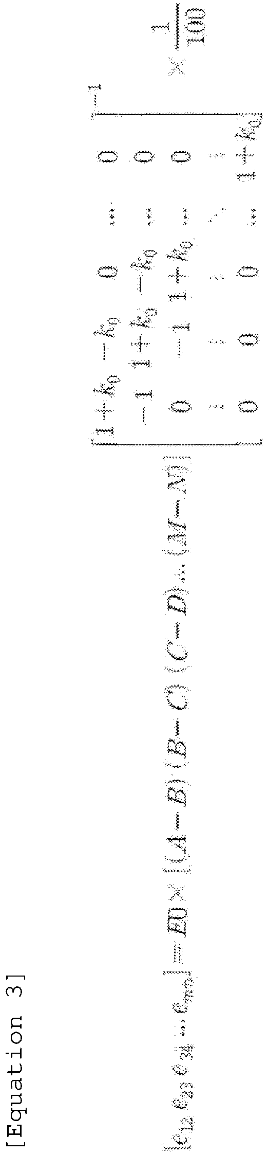
- However, the present invention is not limited thereto, and the
RMBS 150 considers both the convenience of calculation and the accuracy of the calculation to calculate the charging powers e12 to emn by assuming that only some of the wireless charging efficiencies among the wireless charging efficiencies k12, k23, k34 to kmn are the same value. -
FIG. 5A is a diagram illustrating charging powers e12 to e34 calculated by theRMBS 150 ofFIG. 1 , according to an embodiment.FIG. 5B is a diagram illustrating charging power moving between thebattery modules 1 to 4 according to the charging powers e12 to e34 calculated inFIG. 5A . - In the description with reference to
FIGS. 5A and5B , theRMBS 150 assumes that the wireless charging efficiencies between thebattery modules 1 to 4 have the same value of '0.7' for convenience of calculation. In addition, in the description referring toFIGS. 5A and5B , it is assumed that the SOC values of thebattery modules 1 to 4 are 70%, 90%, 80%, and 60%, respectively, and the converted power E0 is 10*104[mWh]. - In the description with reference to
FIGS. 5A and5B , for convenience of explanation, it is assumed that wireless charging is performed between the fourbattery modules 1 to 4, but the present invention is not limited thereto. - The
RMBS 150 may calculate the charging powers e12 to e34 based on [Equation 2] described with reference toFIG. 4 . As a result of the calculation, the charging powers e12 to e34 may be -270 [Wh], 1540 [Wh], and 1840 [Wh], respectively. According to the calculation result, theRMBS 150 may control thebattery module 2 and thebattery module 1 so that 270 [Wh] is output from thebattery module 2 to thebattery module 1. TheRMBS 150 may control thebattery module 2 and thebattery module 3 so that 1540 [Wh] is output from thebattery module 2 to thebattery module 3. TheRMBS 150 may control thebattery module 3 and thebattery module 4 so that 1840 [Wh] is output from thebattery module 3 to thebattery module 4. - Due to wireless charging between the
battery modules 1 to 4 under the control of theRMBS 150, cell balancing between thebattery modules 1 to 4 may be achieved. -
FIG. 6 is a flowchart illustrating a wireless charging operation between thebattery modules 1 to 4 ofFIG. 5B . - Referring to
FIG. 6 , a method for thebattery modules 1 to 4 ofFIG. 5B to perform a wireless charging operation under the control of theRMBS 150 will be described. - In operation S110, the
battery module 1 may output information on the SOC value of thebattery module 1 to theRMBS 150. - In operation S112, the
battery module 2 may output information on the SOC value of thebattery module 2 to theRMBS 150. - In operation S114, the
battery module 3 may output information on the SOC value of thebattery module 3 to theRMBS 150. - In operation S116, the
battery module 4 may output information on the SOC value of thebattery module 4 to theRMBS 150. - In operation S200, the
RMBS 150 may calculate the charging powers e12, e23, and e34 based on information (e.g., SOC values) received from thebattery modules 1 to 4. However, the present invention is not limited thereto, and thebattery modules 1 to 4 may output the voltage of each of the battery cells or the sum of the voltages of the battery cells. TheRMBS 150 may calculate the SOC values of thebattery modules 1 to 4 and calculate the charging powers e12, e23, and e34, based on the information received from thebattery modules 1 to 4. - In operation S310, the
RMBS 150 may output information on the charging power e12 to thebattery module 1. Thebattery module 1 may prepare to receive power based on the information received from theRMBS 150. - In operation S320, the
RMBS 150 may output information on the charging power e12 and e23 to thebattery module 2. Thebattery module 2 may prepare to output power based on the information received from theRMBS 150. - In operation S330, the
RMBS 150 may output information on the charging power e23 and e34 to thebattery module 3. Thebattery module 3 may prepare to output power and prepare to receive power based on the information received from theRMBS 150. - In operation S340, the
RMBS 150 may output information on the charging power e34 to thebattery module 4. Thebattery module 4 may prepare to receive power based on the information received from theRMBS 150. - In operation S400, the
battery module 2 may output charging power e12 to thebattery module 1 based on the information received by operation S320. - In operation S450, the
battery module 1 may receive charging power e12 from thebattery module 2 based on the information received by operation S320. Thebattery module 1 may charge the battery cells of thebattery module 1 by using the charging power e12 received from thebattery module 2. - In operation S500, the
battery module 2 may output charging power e23 to thebattery module 3 based on the information received by operation S320. - In operation S550, the
battery module 3 may receive charging power e23 from thebattery module 2 based on the information received by operation S330. Thebattery module 3 may charge the battery cells of thebattery module 3 by using the charging power e23 received from thebattery module 2. - In operation S600, the
battery module 3 may output charging power e34 to thebattery module 4 based on the information received by operation S330. - In operation S650, the
battery module 4 may receive charging power e34 from thebattery module 3 based on the information received by operation S340. Thebattery module 4 may charge the battery cells of thebattery module 4 by using the charging power e34 received from thebattery module 3. -
FIG. 7 is a conceptual diagram for explaining wireless charging between thebattery modules 1 to 4 ofFIG. 1 according to another embodiment. For convenience of explanation, although only the wireless charging between the fourbattery modules 1 to 4 among thebattery modules 1 to n ofFIG. 1 is described, it is obvious that the wireless charging method may be extended to thebattery modules 1 to n. - As described with reference to
FIG. 4 , any of thebattery modules 1 to 4 may wirelessly charge one or more battery modules adjacent to each other. For example, thebattery module 2 may be wirelessly charged with thebattery modules battery modules 1 to 4 arranged in a line. - The SOC values of the
battery modules 1 to 4 are A(%), B(%), C(%), and D(%), respectively. TheRMBS 150 may receive information on SOC values of thebattery modules 1 to 4. - Referring to
FIG. 7 , during wireless charging between the battery module a and the battery module b, charging power moving between the battery module a and the battery module b is expressed as 'pab'. The absolute value of charging power pab indicates the amount of charging power that moves between the battery module a and the battery module b, and the sign of charging power pab indicates the direction of charging power moving between the battery module a and the battery module b. When charging power pab is a positive number, the battery module a may transmit power as much as an absolute value of the charging power pab to the battery module b. When charging power pab is a negative number, the battery module b may transmit power as much as an absolute value of the charging power pab to the battery module a. - The
RMBS 150 may calculate the charging power pab based on [Equation 4] below.
- The converted power E0 in [Equation 4] may be calculated by [Equation 2]. The conversion value h0 in [Equation 4] may be determined based on wireless charging efficiency between battery modules a and b, the distance between battery modules a and b, the SOC values of battery modules a and b, the types of antennas of battery modules a and b, the number of turns of the coils constituting the antennas, and the like. The conversion value h0 may be a value that changes based on SOC values of the battery modules a and b.
-
FIG. 8 is a diagram illustrating charging power moving between thebattery modules 1 to 4 according to the method described with reference toFIG. 7 . - In the description referring to
FIG. 7 , it is assumed that the converted power E0 is 104 [Wh] for the convenience of calculation in theRMBS 150. In the description with reference toFIG. 8 , for convenience of explanation, it is assumed that wireless charging is performed between the fourbattery modules 1 to 4, but the present invention is not limited thereto. - The
RMBS 150 may calculate the charging powers p12 to p34 based on [Equation 4] described with reference toFIG. 7 . As a result of the calculation, the charging powers p12 to p34 may be -2000*h0[Wh], 1000*h0[Wh], and 2000*h0[Wh], respectively. According to the calculation result, theRMBS 150 may control thebattery module 2 and thebattery module 1 so that 2000*h0 [Wh] is output from thebattery module 2 to thebattery module 1. TheRMBS 150 may control thebattery module 2 and thebattery module 3 so that 1000*h0 [Wh] is output from thebattery module 2 to thebattery module 3. TheRMBS 150 may control thebattery module 3 and thebattery module 4 so that 2000*h0 [Wh] is output from thebattery module 3 to thebattery module 4. - Due to wireless charging between the
battery modules 1 to 4 under the control of theRMBS 150, cell balancing between thebattery modules 1 to 4 may be achieved. -
FIG. 9 is a diagram illustrating a hardware configuration of a BMS according to an embodiment of the present invention. - Referring to
FIG. 9 , a BMS 800 may include a microcontroller (MCU) 810 for controlling various processes and each configuration, a memory 820 on which an operating system program and various programs (e.g., a battery diagnosis program, a voltage approximation calculation program, etc.) are recorded, an input/output interface 830 for providing an input interface and an output interface between the battery cell module and/or the semiconductor switching element, and a communication interface 840 capable of communicating with the outside through a wired/wireless communication network. In this way, the computer program according to the present invention may be recorded in the memory 820 and processed by the microcontroller 810, and for example, may be implemented as a module that performs each functional block shown inFIG. 3 . - The above are specific embodiments for carrying out the present invention. The present invention will include not only the above-described embodiments, but also simple design changes or easily changeable embodiments. In addition, the present invention will include techniques that may be easily modified and implemented using the embodiments. Therefore, the scope of the present invention should not be limited to the above-described embodiments, but should be defined by the claims described below as well as the claims and equivalents of the present invention.
Claims (13)
- A battery management system comprising:a communication unit configured to receive information on a first state of charge (SOC) of a first battery module and a second SOC of a second battery module; anda controller configured to control first wireless charging between the first battery module and the second battery module for balancing between the first SOC and the second SOC,wherein the first wireless charging is to wirelessly transmit power from one of the first battery module and the second battery module to the other battery module.
- The battery management system of claim 1, wherein the communication unit receives information on a third SOC of a third battery module,wherein the controller is configured to control second wireless charging between the second battery module and the third battery module for balancing between the first SOC, the second SOC, and the third SOC,wherein the second wireless charging is to wirelessly transmit power from one of the second battery module and the third battery module to the other battery module.
- The battery management system of claim 2, wherein the controller is configured to control the first wireless charging and the second wireless charging such that a sum of an absolute value of a difference between the first SOC and the second SOC and an absolute value of a difference between the second SOC and the third SOC decreases.
- The battery management system of claim 2, wherein the first SOC is a sum of SOCs of first battery cells in the first battery module,wherein the second SOC is a sum of SOCs of second battery cells in the second battery module,wherein the third SOC is a sum of SOCs of third battery cells in the third battery module.
- The battery management system of claim 2, wherein one battery module is positioned between the first battery module and the third battery module,
wherein the one battery module is the second battery module. - The battery management system of claim 2, wherein the controller is configured to control the first wireless charging and the second wireless charging based on the first SOC, the second SOC, the third SOC, a first wireless charging efficiency between the first battery module and the second battery module, and a second wireless charging efficiency between the second battery module and the third battery module,
wherein the first wireless charging efficiency is determined based on a distance between the first battery module and the second battery module, types of antennas for power transmission and reception of the first battery module and the second battery module, and the number of turns of coils constituting the antennas. - The battery management system of claim 2, wherein the controller is configured to:determine a first direction and a first magnitude of the first wireless charging, and a second direction and a second magnitude of the second wireless charging, according to a determinant,control the first battery module or the second battery module such that when the first direction is a negative number, power of the first magnitude is transmitted from the second battery module to the first battery module, and when the first direction is a positive number, the power of the first magnitude is transmitted from the first battery module to the second battery module, andcontrol the second battery module or the third battery module such that when the second direction is a negative number, power of the second magnitude is transmitted from the third battery module to the second battery module, and when the second direction is a positive number, the power of the second magnitude is transmitted from the second battery module to the third battery module.
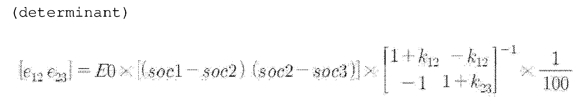 (E0 is a constant, a sign and magnitude of e12 are the first direction and the first magnitude, a sign and magnitude of e23 are the second direction and the second magnitude, soc1 is the first SOC, soc2 is the second SOC, soc3 is the third SOC, k12 is the first wireless charging efficiency, k23 is the second wireless charging efficiency)
 - The battery management system of claim 7, wherein E0 is determined by an equation.

- A battery rack comprising:a plurality of battery modules; anda battery management system configured to control wireless charging between neighboring battery modules such that a sum of absolute differences of SOCs of the neighboring battery modules among the plurality of battery modules decreases, and control the first battery module such that power is output from a first battery module among the neighboring battery modules to a second battery module,wherein an SOC of the first battery module is greater than an SOC of the second battery module,wherein the first battery module comprises a first antenna on one surface facing the second battery module, and transmits the power through the first antenna.
- The battery rack of claim 9, wherein the second battery module comprises a second antenna on one surface facing the first battery module, and receives the power through the second antenna.
- The battery rack of claim 9, wherein the battery management system is configured to control the wireless charging between the neighboring battery modules through Controller Area Network (CAN) communication.
- The battery rack of claim 9, wherein the battery management system is configured to calculate the power according to Equation 1.

- The battery rack of claim 12, wherein E0 is determined by Equation 2,
wherein h0 is determined based on at least one of a distance between the first battery module and the second battery module, a type of the first antenna, the number of turns of a coil constituting the first antenna, an SOC of the first battery module, and an SOC of the second battery module.
Applications Claiming Priority (2)
| Application Number | Priority Date | Filing Date | Title |
|---|---|---|---|
| KR1020200072623A KR20210155290A (en) | 2020-06-15 | 2020-06-15 | Battery management system and battery rack for wireless charging |
| PCT/KR2021/007445 WO2021256817A1 (en) | 2020-06-15 | 2021-06-15 | Battery management system and battery rack for wireless charging |
Publications (2)
| Publication Number | Publication Date |
|---|---|
| EP4080717A1 true EP4080717A1 (en) | 2022-10-26 |
| EP4080717A4 EP4080717A4 (en) | 2023-07-19 |
Family
ID=79164321
Family Applications (1)
| Application Number | Title | Priority Date | Filing Date |
|---|---|---|---|
| EP21826854.8A Pending EP4080717A4 (en) | 2020-06-15 | 2021-06-15 | Battery management system and battery rack for wireless charging |
Country Status (6)
| Country | Link |
|---|---|
| US (1) | US20230050428A1 (en) |
| EP (1) | EP4080717A4 (en) |
| JP (1) | JP2023509530A (en) |
| KR (1) | KR20210155290A (en) |
| CN (1) | CN115023873A (en) |
| WO (1) | WO2021256817A1 (en) |
Families Citing this family (1)
| Publication number | Priority date | Publication date | Assignee | Title |
|---|---|---|---|---|
| JP2021181141A (en) * | 2020-05-20 | 2021-11-25 | セイコーエプソン株式会社 | Charging method and charging system |
Family Cites Families (6)
| Publication number | Priority date | Publication date | Assignee | Title |
|---|---|---|---|---|
| KR101249972B1 (en) * | 2010-08-17 | 2013-04-03 | 정윤이 | Battery pack and active cell balancing method of battery pack |
| JP5760877B2 (en) * | 2011-09-07 | 2015-08-12 | 日産自動車株式会社 | Battery control device |
| KR101457191B1 (en) * | 2012-08-24 | 2014-10-31 | 서울대학교산학협력단 | Battery Pack, Battery Apparatus and Cell Balancing Method Therefor |
| KR20160129617A (en) * | 2015-04-30 | 2016-11-09 | 삼성에스디아이 주식회사 | Cell balancing method and battery management system using the cell balancing method |
| KR102399604B1 (en) * | 2017-08-28 | 2022-05-18 | 삼성전자주식회사 | Apparatus and system for managing battery |
| JP2020089055A (en) * | 2018-11-26 | 2020-06-04 | 株式会社村田製作所 | Cell balance system user interface |
-
2020
- 2020-06-15 KR KR1020200072623A patent/KR20210155290A/en active Search and Examination
-
2021
- 2021-06-15 WO PCT/KR2021/007445 patent/WO2021256817A1/en unknown
- 2021-06-15 JP JP2022542029A patent/JP2023509530A/en active Pending
- 2021-06-15 EP EP21826854.8A patent/EP4080717A4/en active Pending
- 2021-06-15 CN CN202180010271.3A patent/CN115023873A/en active Pending
- 2021-06-15 US US17/794,336 patent/US20230050428A1/en active Pending
Also Published As
| Publication number | Publication date |
|---|---|
| KR20210155290A (en) | 2021-12-22 |
| US20230050428A1 (en) | 2023-02-16 |
| EP4080717A4 (en) | 2023-07-19 |
| CN115023873A (en) | 2022-09-06 |
| JP2023509530A (en) | 2023-03-08 |
| WO2021256817A1 (en) | 2021-12-23 |
Similar Documents
| Publication | Publication Date | Title |
|---|---|---|
| EP3185388B1 (en) | Battery control method and apparatus, and battery pack | |
| EP3171483B1 (en) | Method and apparatus for battery equalization, and battery pack using the same | |
| US9488977B2 (en) | Power storage system having modularized BMS connection structure and method for controlling the system | |
| JP5975169B2 (en) | Charge / discharge device, charge / discharge control method, and program | |
| US11912158B2 (en) | Battery management apparatus, battery management method, battery pack, and electric vehicle | |
| Chaturvedi et al. | Modeling, estimation, and control challenges for lithium-ion batteries | |
| EP3056918B1 (en) | Apparatus for estimating state of hybrid secondary battery and method therefor | |
| EP3026752A1 (en) | Battery pack and method for controlling the same | |
| KR20190036242A (en) | Apparatus for equalizing battery module, battery pack including the same, and vehicle | |
| US9234944B2 (en) | SOC correcting system having multiple packs in parallel | |
| EP3059600B1 (en) | Apparatus for estimating voltage of hybrid secondary battery and method therefor | |
| US20220029204A1 (en) | Battery system and slave battery management system | |
| WO2012091434A2 (en) | Method and device for calculating state of health in secondary battery | |
| CN110679056A (en) | Battery charging management apparatus and method | |
| EP4080717A1 (en) | Battery management system and battery rack for wireless charging | |
| US10374442B2 (en) | Integrated multiple voltage energy storage system and method | |
| US11336100B2 (en) | System and method for balancing state of charge of battery | |
| EP4050697B1 (en) | Method and apparatus for equalizing a battery module, battery module, and power management controller | |
| EP3974850A1 (en) | Parallel battery relay diagnosis device and method | |
| KR101915183B1 (en) | Apparatus and method for setting and operating reference SOC of active cell balancing using common bus | |
| EP4236013A1 (en) | Battery control system and method | |
| KR102589740B1 (en) | Battery charger and discharger for charging and discharging battery | |
| US20220344767A1 (en) | Power systems comprising battery arrays | |
| KR20240055537A (en) | Battery management apparatus and operating method of the same, battery system | |
| CN115149127A (en) | Method for charging and discharging battery, electronic device, and storage medium |
Legal Events
| Date | Code | Title | Description |
|---|---|---|---|
| STAA | Information on the status of an ep patent application or granted ep patent |
Free format text: STATUS: THE INTERNATIONAL PUBLICATION HAS BEEN MADE |
|
| PUAI | Public reference made under article 153(3) epc to a published international application that has entered the european phase |
Free format text: ORIGINAL CODE: 0009012 |
|
| STAA | Information on the status of an ep patent application or granted ep patent |
Free format text: STATUS: REQUEST FOR EXAMINATION WAS MADE |
|
| 17P | Request for examination filed |
Effective date: 20220719 |
|
| AK | Designated contracting states |
Kind code of ref document: A1 Designated state(s): AL AT BE BG CH CY CZ DE DK EE ES FI FR GB GR HR HU IE IS IT LI LT LU LV MC MK MT NL NO PL PT RO RS SE SI SK SM TR |
|
| A4 | Supplementary search report drawn up and despatched |
Effective date: 20230619 |
|
| RIC1 | Information provided on ipc code assigned before grant |
Ipc: H01M 10/46 20060101ALI20230613BHEP Ipc: H02J 50/80 20160101ALI20230613BHEP Ipc: H02J 50/10 20160101ALI20230613BHEP Ipc: H02J 7/00 20060101AFI20230613BHEP |
|
| DAV | Request for validation of the european patent (deleted) | ||
| DAX | Request for extension of the european patent (deleted) |