EP4080707A1 - Inter-harmonic damping system and method - Google Patents
Inter-harmonic damping system and method Download PDFInfo
- Publication number
- EP4080707A1 EP4080707A1 EP21382336.2A EP21382336A EP4080707A1 EP 4080707 A1 EP4080707 A1 EP 4080707A1 EP 21382336 A EP21382336 A EP 21382336A EP 4080707 A1 EP4080707 A1 EP 4080707A1
- Authority
- EP
- European Patent Office
- Prior art keywords
- inter
- harmonic
- wind turbine
- control unit
- resonant
- Prior art date
- Legal status (The legal status is an assumption and is not a legal conclusion. Google has not performed a legal analysis and makes no representation as to the accuracy of the status listed.)
- Pending
Links
Images



Classifications
-
- H—ELECTRICITY
- H02—GENERATION; CONVERSION OR DISTRIBUTION OF ELECTRIC POWER
- H02P—CONTROL OR REGULATION OF ELECTRIC MOTORS, ELECTRIC GENERATORS OR DYNAMO-ELECTRIC CONVERTERS; CONTROLLING TRANSFORMERS, REACTORS OR CHOKE COILS
- H02P9/00—Arrangements for controlling electric generators for the purpose of obtaining a desired output
- H02P9/10—Control effected upon generator excitation circuit to reduce harmful effects of overloads or transients, e.g. sudden application of load, sudden removal of load, sudden change of load
- H02P9/105—Control effected upon generator excitation circuit to reduce harmful effects of overloads or transients, e.g. sudden application of load, sudden removal of load, sudden change of load for increasing the stability
-
- H—ELECTRICITY
- H02—GENERATION; CONVERSION OR DISTRIBUTION OF ELECTRIC POWER
- H02J—ELECTRIC POWER NETWORKS; CIRCUIT ARRANGEMENTS OR SYSTEMS FOR SUPPLYING OR DISTRIBUTING ELECTRIC POWER; SYSTEMS FOR STORING ELECTRIC ENERGY
- H02J3/00—Circuit arrangements for AC mains or AC distribution networks
- H02J3/01—Arrangements for reducing harmonics or ripples
-
- H—ELECTRICITY
- H02—GENERATION; CONVERSION OR DISTRIBUTION OF ELECTRIC POWER
- H02J—ELECTRIC POWER NETWORKS; CIRCUIT ARRANGEMENTS OR SYSTEMS FOR SUPPLYING OR DISTRIBUTING ELECTRIC POWER; SYSTEMS FOR STORING ELECTRIC ENERGY
- H02J3/00—Circuit arrangements for AC mains or AC distribution networks
- H02J3/38—Arrangements for feeding a single network from two or more generators or sources in parallel; Arrangements for feeding already energised networks from additional generators or sources in parallel
- H02J3/381—Dispersed generators
-
- H—ELECTRICITY
- H02—GENERATION; CONVERSION OR DISTRIBUTION OF ELECTRIC POWER
- H02P—CONTROL OR REGULATION OF ELECTRIC MOTORS, ELECTRIC GENERATORS OR DYNAMO-ELECTRIC CONVERTERS; CONTROLLING TRANSFORMERS, REACTORS OR CHOKE COILS
- H02P9/00—Arrangements for controlling electric generators for the purpose of obtaining a desired output
- H02P9/04—Control effected upon non-electric prime mover and dependent upon electric output value of the generator
-
- H—ELECTRICITY
- H02—GENERATION; CONVERSION OR DISTRIBUTION OF ELECTRIC POWER
- H02J—ELECTRIC POWER NETWORKS; CIRCUIT ARRANGEMENTS OR SYSTEMS FOR SUPPLYING OR DISTRIBUTING ELECTRIC POWER; SYSTEMS FOR STORING ELECTRIC ENERGY
- H02J2101/00—Supply or distribution of decentralised, dispersed or local electric power generation
- H02J2101/20—Dispersed power generation using renewable energy sources
- H02J2101/28—Wind energy
-
- H—ELECTRICITY
- H02—GENERATION; CONVERSION OR DISTRIBUTION OF ELECTRIC POWER
- H02P—CONTROL OR REGULATION OF ELECTRIC MOTORS, ELECTRIC GENERATORS OR DYNAMO-ELECTRIC CONVERTERS; CONTROLLING TRANSFORMERS, REACTORS OR CHOKE COILS
- H02P2101/00—Special adaptation of control arrangements for generators
- H02P2101/15—Special adaptation of control arrangements for generators for wind-driven turbines
-
- Y—GENERAL TAGGING OF NEW TECHNOLOGICAL DEVELOPMENTS; GENERAL TAGGING OF CROSS-SECTIONAL TECHNOLOGIES SPANNING OVER SEVERAL SECTIONS OF THE IPC; TECHNICAL SUBJECTS COVERED BY FORMER USPC CROSS-REFERENCE ART COLLECTIONS [XRACs] AND DIGESTS
- Y02—TECHNOLOGIES OR APPLICATIONS FOR MITIGATION OR ADAPTATION AGAINST CLIMATE CHANGE
- Y02E—REDUCTION OF GREENHOUSE GAS [GHG] EMISSIONS, RELATED TO ENERGY GENERATION, TRANSMISSION OR DISTRIBUTION
- Y02E10/00—Energy generation through renewable energy sources
- Y02E10/70—Wind energy
- Y02E10/72—Wind turbines with rotation axis in wind direction
-
- Y—GENERAL TAGGING OF NEW TECHNOLOGICAL DEVELOPMENTS; GENERAL TAGGING OF CROSS-SECTIONAL TECHNOLOGIES SPANNING OVER SEVERAL SECTIONS OF THE IPC; TECHNICAL SUBJECTS COVERED BY FORMER USPC CROSS-REFERENCE ART COLLECTIONS [XRACs] AND DIGESTS
- Y02—TECHNOLOGIES OR APPLICATIONS FOR MITIGATION OR ADAPTATION AGAINST CLIMATE CHANGE
- Y02E—REDUCTION OF GREENHOUSE GAS [GHG] EMISSIONS, RELATED TO ENERGY GENERATION, TRANSMISSION OR DISTRIBUTION
- Y02E40/00—Technologies for an efficient electrical power generation, transmission or distribution
- Y02E40/40—Arrangements for reducing harmonics
Definitions
- the present invention relates to a wind turbine control system and to a method for damping inter-harmonics of a wind turbine.
- Inter-harmonics are non-integer multiples of the fundamental frequency that may appear in an electric power generating system such as a wind turbine as consequence of the generator structure.
- an electric power generating system such as a wind turbine as consequence of the generator structure.
- it is known to add a specific damping hardware.
- this hardware addition involves structural problems and it is usually costly and complex to install.
- damping control systems such as resonant controllers to tackle harmonic suppression is known, see for example J. Moriano, PhD: Contributions to the Multifrequency Control of Grid-Tied Voltage Source Converter, 2018 .
- current damping systems are not efficient when damping inter-harmonics.
- the goal would be providing new control strategies and/or systems for damping inter-harmonics in a reliable, retro-compatible and cost-effective way.
- each inter-harmonic is non-integer multiples of the fundamental frequency, that appear at an electric generator. Contrary to harmonics, each inter-harmonic comprises two components: a direct component and an inverse component.
- such components may be symmetric, e.g. to the fundamental frequency, or not.
- the inter-harmonic A In stationary reference frame, i.e. ⁇ reference frame, the inter-harmonic A would have ⁇ A components; while in synchronous reference frame, i.e. dq reference frame, the same inter-harmonic would have -A1 and +A2 components.
- Inter-harmonics may be generated due to the design of the electric generator. Inter-harmonics may also depend on the operational point of the generator i.e., on the rotational speed of the rotor. That is, contrary to harmonics, which have fixed values, upon a change in the operational point e.g. due to a variation of the speed of the rotor; the inter-harmonics order or components are moved accordingly. Indeed, the inter harmonics existing in the rotor, in ⁇ stationary reference frame are highly dependent on the rotor speed and/or the slip.
- the inter-harmonic components may be at 622 Hz and at 722 Hz, or when dividing by the fundamental frequency of the grid, e.g. 50 Hz, the inter-harmonic direct component and indirect component may be 12.5 and 14.5, respectively (or 12.5 th and 14.5 th , respectively).
- the inter harmonic order h may be calculated dividing the inter-harmonic frequency fSH by the fundamental frequency f0.
- wind turbine comprises an electric generator, a converter and a control system.
- the electric generator comprises a rotor configured to rotate at different rotation speeds thereby operating at different operation points, and a converter having a rotor side converter and a power consumption system, i.e. grid-side, side converter.
- the control system comprises a current control loop and an inter-harmonic damping control unit arranged in parallel to the current control loop.
- the inter-harmonic damping control unit damping control unit comprises at least a resonant controller which is dependent on the operation point for tracking and damping the one or more inter harmonic(s) of the wind turbine, i.e. of the generator of the wind turbine.
- inter-harmonic control system which is dependent on the operational point enables an effective damping of inter-harmonics, as inter-harmonics are dependent on the operation point and move along a horizontal axis according to its variations.
- Such an inter-harmonic control system is therefore made adaptative, that is, it may adapt its performance according to the operation point to track and determine the location of the inter-harmonics to be damped.
- An effective inter-harmonic damping system may thus be obtained for any operational scenario as it may be dynamically adapted to the changing operation conditions.
- the control system may retro-compatible, that is, it may be compatible with previous control structure thereby saving both time and costs as there may no need to replace previous or pre-existing control system, and also facilitating its implementation.
- control system enables complying with the grid code requirements as enables effective damping the inter-harmonic(s) whichever the operation point is.
- the inter-harmonic damping control unit may comprise a plurality of resonant controllers arranged in parallel thereby improving the number of inter-harmonics to be managed by the control system.
- Resonant controllers provide infinite gain at a desired or target frequency, in other words, they may provide a very specific and narrow filter which effectively damps a predefined frequency.
- Several resonant controllers are known, for instance, Second Order Generalized Integrator (SOGI)-filter based and Reduced Order Generalized Integrator (ROGI)-filter based controllers.
- SOGI-filter based controllers affect equally the dynamics of the direct and inverse components while ROGI-filter based controllers affect each component dynamics in a different way.
- ROGI filter-based controller may obtain an infinite gain in a single frequency.
- the number of resonant controllers may depend on the reference frame, i.e. an abstract coordinate system such as stationary frame ⁇ or synchronous reference frame dq ; and may be proportional to the number of inter-harmonics to be damped, a more versatile control system may thus be obtained as it may be adapted and/or be implemented according to the requirements of each case.
- the number of resonant controllers may be equal to the number of inter-harmonics to be damped thereby decreasing the number of required resonant controller(s) as a single resonant controller may be configured to deal with, i.e. to damp, an inter-harmonic.
- the resonant controller(s) may be a SOGI-filter based controller(s).
- two resonant controllers may be used wherein such resonant controllers may be SOGI-filter based controllers.
- a single SOGI-filter based configured to damp both components i.e. direct and inverse components, of each inter-harmonic may suffice.
- the number of resonant controllers may be twice the number of inter-harmonics to be damped.
- the direct component and the indirect component of each inter-harmonic may be independently affected e.g. in synchronous dq reference frame wherein the components of an inter-harmonic are not symmetric with respect to the fundamental frequency.
- the at least one resonant controller may be a SOGI-filter based controller which enables reducing the number of controllers.
- each SOGI- filter based controller is able to handle, i.e. to damp, both components of each inter-harmonic e.g. in stationary ⁇ reference frame, a single SOGI per inter-harmonic may suffice. The implementation complexity and cost may thus be reduced.
- the plurality of resonant controllers may be ROGI-filter based controllers, SOGI-filter based controllers or a combination thereof.
- the control system is thus more versatile as different types of resonant controllers may be arranged within the same structure.
- each inter-harmonic component i.e. the direct or the inverse component, may be affected differently. Therefore, the system enables damping and/or affecting each inter-harmonic component independently e.g. with different dynamic.
- the at least one resonant controller may be implemented at the power consumption system side converter thereby a more efficient control strategy may be implemented as it is directly coupled to the power consumption system e.g. a grid.
- the at least one resonant controller may be implemented at rotor side converter (RSC).
- the inter-harmonic control may comprise at least a resonant controller implemented at the power consumption system side converter and at least a resonant controller implemented at the rotor side converter (RSC) thereby allowing implementing a control system with further flexibility.
- RSC rotor side converter
- the introduction of resonant controller(s) in one side of the converter may cause oscillations to arise in the DC link.
- the control system may be implemented at both sides of the converter which enhances the protection of the wind turbine. Therefore, the wind turbine comprises an improved efficiency, longer lifetime and better-quality energy production.
- the electric generator may be a Doubly-Fed Induction Generator (DFIG).
- DFIG Doubly-Fed Induction Generator
- the wind turbine is a DFIG wind turbine. In another example, the wind turbine is a Full Converter wind turbine.
- a method for damping the inter-harmonic(s) of a wind turbine comprises determining the operation point of the wind turbine by measuring the rotational speed of the rotor, and adapting the inter-harmonic damping control unit to the operation point and damping the inter-harmonics of the wind turbine by the inter-harmonic damping control unit.
- the method enables effectively damping the inter harmonic(s) present in a wind turbine, i.e. in the generator of the wind turbine.
- the inter-harmonics may be tracked and/or determined for the on-going operating conditions.
- the inter-harmonic(s) may be effectively damped and the grid requirements whichever the operation point is.
- adapting the inter-harmonic damping control unit to the operation point may comprise iteratively increasing the gain (K) of the transfer function of the inter-harmonic damping control unit, starting from a minimum gain and by adding a predefined increase ( ⁇ h), until the Total Harmonic Current Distortion (THDc) is complied.
- K gain
- ⁇ h predefined increase
- TDDc Total Harmonic Current Distortion
- adapting the inter-harmonic damping control unit to the operation point may comprise comparing the measured rotor speed with a plurality of predefined rotor speed value ranges of a pre-stablished gain schedule, wherein each predefined rotor speed value range comprises associated inter-harmonic related coefficients; and replacing the inter-harmonic related coefficients of the predefined rotor speed value range within which the measured rotor speed falls in the transfer function of the inter-harmonic damping control.
- inter-harmonic shall be understood as a non-integer harmonic of the fundamental frequency. Each inter-harmonic comprises a direct component and an inverse component. The term “inter-harmonic” shall be understood as comprising both inter-harmonic components. The terms “inter-harmonic” and “inter-harmonic component(s) are herein interchangeably used”.
- inverse component of an inter-harmonic shall be understood as the component located in the negative axis of a reference frame.
- operation point shall be understood as the on-going working/operating state of a device, e.g. a wind turbine, at a predetermined speed, such state being dependent on the rotatory speed of the rotor.
- operating point or “point of operation” shall be regarded as synonyms and are interchangeably used herein.
- the term "parallel to the current control loop” shall be understood as a device arranged to receive the same input as the current control loop, e.g. the contribution of the reference current i*_ ⁇ , i*_dq and the measured current 1_ ⁇ , i_dq; and also arranged to enable a contribution between the current control loop output and its own output i.e. the output of a single module or the contribution of each module output in case a plurality of modules is used.
- the term "damping" shall be understood reducing the amplitude of a certain predetermined frequency. Usually, a frequency component having the opposite value of the frequency to be damped is generated. thereby counterbalancing the predetermined frequency i.e. the sum of both values would be around 0.
- Total Harmonic Current Distortion shall be understood as a measurement of the harmonic distortion present in a system which is defined as the ratio of the sum of the power of all harmonic current components to the power of the fundamental frequency current. It is usually imposed by the grid operators as part of the grid requirements in each country/region.
- Proportional Integer (PI) controller shall be understood as a control wherein only the proportional and integral terms are used.
- Proportional Integer control and Proportional Integral control are interchangeably used herein.
- Figure 1 illustrates an exemplary wind turbine WT according to an example.
- the wind turbine WT of Figure 1 may comprise a nacelle 10 which may house a power generator 20.
- the nacelle 10 may be mounted on a tower 14.
- Figure 1 discloses a portion of the tower 14, however, the tower 14 may have any height that facilitates the operation of a wind turbine WT according to any of the examples herein disclosed, such height may depend e.g. on the specific site requirements.
- the wind turbine WT may also comprise a rotor hub connected to a plurality, e.g. three, blades 12 extending radially outwardly from the hub for converting the wind energy into rotational energy.
- the wind turbine WT may have any other number of blades 12 that facilitates operation of the wind turbine WT.
- the blades may have any length and/or shape.
- the power generator 20 e.g. a Doubly Fed Induction Generator (DFIG) or a Full Converter (FC) generator, may comprise a rotor 21 configured to rotate at different rotation speeds thereby operating at different operation points.
- the generator 20 may be coupled to a power converter 30, or to a power converter system, that may convert a substantially Direct Current (DC) power output from the power generator to Alternating Current (AC) power.
- the AC power may be transmitted or injected into an electrical distribution network, i.e. a grid.
- the converter may comprise a Rotor Side Converter 31 and a Grid Side Converter or power consumption system side converter 32.
- the power system may comprise solar panels coupled to form one or more solar arrays.
- the power system may comprise s a plurality of solar panels and/or solar arrays coupled together in a series and/or parallel to facilitate generating a desired current and/or voltage output.
- Each solar panel may comprise one or more photovoltaic panel(s), a solar thermal collector or any other device that converts solar energy to electrical energy e.g. substantially direct current.
- the solar panel(s) may be coupled to the power converter.
- the power converter may be configured to adjust the amplitude of the voltage and/or current of the converted AC power to an amplitude suitable for the grid.
- the power converter may be configured to provide AC power at a frequency and a phase that are substantially equal to the grid frequency and phase.
- the power converter may provide three phase AC power.
- the power converter may provide single phase AC power or any other number of phases of AC power.
- the wind turbine WT of figure 1 may also comprise a control system 100 which may comprise a current control loop 110 and an inter-harmonic damping control unit 120 according to any of the examples disclosed herein.
- the inter-harmonic damping control unit 120 may be arranged in parallel to the current control loop.
- the wind turbine WT may be configured to operate in a wind turbine farm.
- Figures 1A and 1B depict, for a predefined operation point, the inverse component 11, 21 and the direct component 12, 22 of a predetermined inter-harmonic in the stationary frame ⁇ and in the synchronous frame dq, respectively.
- Figure 1A shows the direct and indirect components 11, 12 of the 12.5 inter-harmonic (or 12.5 th inter-harmonic) in the stationary reference frame ⁇ .
- the inverse component is located at -12.5 and the direct component at +12.5.
- the components of the inter-harmonic are symmetric to the vertical axis.
- Figure 1A also depicts the fundamental frequency located at +1 and two harmonics located at -5 and +7.
- Figure 2 depicts a control system 100 of a wind turbine according to Figure 1 , which may be configured to be coupled to a power consumption system, e.g. an electrical grid.
- the wind turbine may comprise an electric generator e.g. a Doubly-Fed Induction Generator (DFIG) with a rotor, and a converter (not shown).
- DFIG Doubly-Fed Induction Generator
- the rotor may be configured to rotate at different rotation speeds thereby achieving different operation points.
- the converter may have a rotor side converter side and a power consumption system side converter e.g. a grid side converter.
- the control system 100 may comprise a current control loop structure 110 e.g. a Proportional Integer or Integral (PI), which may be a standard current control loop.
- PI Proportional Integer or Integral
- the control loop 110 may receive as input the deviation between the reference current 1*_ ⁇ e.g. established by a preceding power control loop (not shown); and the measured current i_ ⁇ , e.g. rotor current.
- the output of the current loop 110 may be added to a feedforward signal e_ ⁇ , e.g. from a subsequent control loop; in order to obtain the voltage reference u*_ ⁇ which may be used in a Pulse Width Modulation (PWM) e.g. after transforming into triphasic system.
- PWM Pulse Width Modulation
- the current control loop may be a proportional integral (PI) control.
- the control system 100 may further comprise an inter-harmonic damping control unit 120 arranged in parallel to the control loop 110.
- the inter-harmonic damping control unit 120 may comprise the input of the current loop i.e. the deviation between the reference current i*_ ⁇ and the measured current i_ ⁇ .
- the output of the inter-harmonic damping control unit 120 may be added to the output of the current control loop thereby contributing to calculate the reference voltage u*_ ⁇ .
- the previous control structure may be kept which enables saving costs and reduces the complexity of adding further elements to a pre-existing control structure.
- the inter-harmonic damping control unit 120 may depend on the operation point of the generator of the wind turbine i.e. may depend on the angular speed of the rotor. That is, the inter-harmonic damping control unit 120 may be configured to be adapted to the on-going operating condition e.g. in order to identify and/or determine the value and position of the inter-harmonic(s) of the wind turbine, as explained later on herein (see Figure 6 ).
- the inter-harmonic damping control unit 120 may be a resonant controller e.g. SOGI-filter based controller, ROGI-filter based controller or any other suitable resonant controller.
- Resonant controllers comprise an infinite gain at resonant frequency and may be used as specific filters to damp a predetermined frequency e.g. the direct and/or inverse component(s) of an inter-harmonic.
- the ROGI-filter based controllers may affect a single inter-harmonic component, i.e. either direct or inverse component; with a predetermined dynamic.
- the SOGI-filter based controllers may affect both the direct and the inverse components of a predetermined inter-harmonic with the same dynamic.
- the inter-harmonic damping control unit 120 may comprise at least one or a plurality of resonant controllers 121, 221, 222, 321, 322 (see Figures 2 - 4 ).
- the resonant controller(s) may be dependent on the operation point of the generator of the wind turbine i.e. may depend on the angular speed of the rotor.
- the resonant controllers may be adapted to be dependent on the operational point.
- inter-harmonic damping control unit comprises a plurality of resonant controllers
- resonant controllers may be arranged in parallel with respect the current control loop and also with respect to each other.
- the implementation of such inter-harmonic damping control unit is thus simple and enables using a pre-existing control structure which allows saving time and costs.
- the possibility of adding more than one module makes the control system versatile and efficient.
- the inter-harmonic damping control unit may comprise a single resonant controller e.g. a SOGI-filter based controller.
- the inter-harmonic damping control unit may comprise a plurality of resonant controllers e.g. SOGI-filter based controllers, ROGI-filter based controllers or a combination thereof.
- SOGI-filter based controllers e.g. SOGI-filter based controllers
- ROGI-filter based controllers e.g. ROGI-filter based controllers
- the versatility of the control system may thus be enhanced and improved.
- the number the resonant controllers may be proportional to the number of inter-harmonics to be damped.
- the number of resonant controllers may be equal to the number of inter-harmonics to be damped. In an alternative example, the number of resonant controllers may be twice the number of inter-harmonics to be damped.
- the number and type of resonant controllers may depend on the reference frame, the dynamics to be obtained and/or the number of inter-harmonics to be damped.
- FIG. 3 depicts a control system 200 implemented in the stationary reference frame ⁇ and for a predetermined operation point.
- the control system 200 may comprise a current control loop 210, e.g. a Proportional Integer (PI), and an inter-harmonic damping control unit comprising a resonant controller 221.
- PI Proportional Integer
- the control system shown in Figure 3 may be implemented in cases where the wind turbine comprises a single inter-harmonic e.g. the 12.5 th inter-harmonic having symmetric direct and indirect components +12.5 and -12.5 in stationary reference frame.
- the resonant controller 221 may be a SOGI-filter based controller which may equally affect the dynamics of both components.
- a single controller may be configured to damp both direct and indirect components, e.g. +12.5 and -12.5, respectively; of the inter-harmonic.
- the use of a SOGI-filter based controller may therefore enable reducing the number of resonant controllers in the stationary frame ⁇ .
- the number of resonant controllers may be equal to the number of inter-harmonics to be damped.
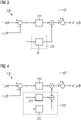
- FIG. 4 shows a control system 300 implemented in the stationary reference frame ⁇ .
- the control system 300 may comprise a current control loop 310, e.g. a Proportional Integer (PI), and an inter-harmonic damping control unit 320 comprising two resonant controllers 321, 322.
- PI Proportional Integer
- the control system shown in Figure 4 may implemented, for instance, in cases where the wind turbine comprises two inter-harmonics e.g. 12.5 and 13.5.
- the resonant controllers 321,322 may be SOGI-filter based controllers. Each SOGI-filter based controller may be configured to damp both components of an inter-harmonic.
- the resonant controller 321 may be configured to damp the components of the 12.5 th inter-harmonic, i.e. the direct component +12.5 and the indirect component -12.5; while the resonant controller 322 may be configured to damp the direct and the indirect components of 13.5 th inter-harmonic, i.e. +13.5 and -13.5, respectively.
- control system 300 may also be implemented for cases in which the wind turbine comprises a single inter-harmonic, e.g. the 12.5 th inter-harmonic, but wherein the components of such inter-harmonic are to be affected by different dynamics.
- the resonant controllers 321, 322 may be ROGI-filter based controllers wherein each resonant controller may be configured to handle a single component e.g. either the direct or the inverse component, of the inter-harmonic.
- the resonant controller 321 may be configured to damp the direct component of the inter-harmonic and the resonant controller 322 may be configured to damp the indirect component; e.g. +12.5 and -12.5, respectively.
- control system comprises a high adaptability and/or flexibility to face different situations.
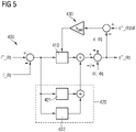
- FIG. 5 depicts a control system 400 implemented in the synchronous reference frame dq.
- the control system 400 may comprise a current control loop 410, e.g. a Proportional Integer (PI), and an inter-harmonic damping control unit 420.
- the control system 400 may further comprise a feedback control loop 430 and a cross-coupling signal cc_dq, as compared to the control structure of the stationary reference frame.
- PI Proportional Integer
- the cross-coupling signal cc_dq e.g. a signal comprising the inter dependency of d and q axis signals, may be a further input signal for calculating the reference voltage u*_dq.
- the feedback control loop 430 may have as input the contribution of: the sum of the output of the current control loop and the output of the inter-harmonic damping control, the feedforward signal, the cross-coupling signal cc_dq, and also the maximum voltage u*_dqsat which may be preestablished.
- the inter-harmonic damping control unit 420 may be arranged in parallel to the current control loop 410, i.e. it may comprise as input the difference between the reference current i*_dq, e.g. established by a preceding power control loop (not shown); and the measured current i_dq e.g. rotor current; whereas the output of the inter-harmonic damping control unit 420 may be added to the output of the current control loop 410 thereby contributing to calculate the reference voltage u*_dq which may be used (after transforming in triphasic signals) into a PWM.
- the inter-harmonic damping control unit 420 may be implemented for example, in cases where the wind turbine comprises a single inter-harmonic, e.g. the 12.5 th inter-harmonic. However, in synchronous reference frame dq, the components of the inter-harmonic(s) are shifted along the horizontal axis and thus, the components of the inter-harmonic(s) are no longer symmetric with respect to the vertical axis or the fundamental frequency. In the example of the 12.5 th inter-harmonic, the direct component would be shifted to 13.5 and the indirect component to -14.5.
- the resonant controllers 421, 422 may be ROGI controllers wherein each ROGI controller may be configured to damp a component of the inter-harmonic.
- resonant controller 421 may be configured to damp the direct component of the inter-harmonic and the resonant controller 422 may be configured to damp the indirect component e.g. +13.5 and - 14.5, respectively.
- the inter-harmonic damping control In order to determine the position and damp the inter-harmonic(s) of a wind turbine, the inter-harmonic damping control, and thus the resonant controller(s), may dependent on the operational point. To do so, the inter-harmonic damping control, i.e. and the resonant controllers, may be made adaptative.
- inter-harmonic damping control unit may be made adaptative online. In an alternative example, the inter-harmonic damping control unit may be made adaptative offline.
- Figure 6 depicts a method 500 for damping inter-harmonics which could be implemented in a wind turbine comprising a control system according to any of the disclosed examples.
- the operation point of the wind turbine may, in block 501, be determined.
- the operation point may be determined by measuring the rotational speed of the rotor.
- the rotational speed of the rotor may be measured e.g. by using a sensor, or it may be calculated with e.g. a Phase Locked Loop (PLL) by using a signal from the PLL or any other suitable method.
- PLL Phase Locked Loop
- the inter-harmonic damping control unit may, in block 502, be adapted to the operation point. There may be at least two different options to adapt the inter-harmonic damping control.
- the gain K of the transfer function of the inter-harmonic damping control unit may be set to be a minimum value (Kmin), e.g. 0.01 or any other suitable value.
- the (minimum) gain may be progressively and/or iteratively increased by a predefined increase ( ⁇ h), e.g. 0.0001, until the Total Harmonic Current Distortion (THDc) is complied.
- THDc relates to the maximum allowed harmonic level and may be part of grid requirements set by each grid operator and thus, the method enables complying with the grid code requirements of each country/region.
- Such predefined increase ( ⁇ h) may be equal to or dependent on the discretization of a speed range e.g. the operational speed range of the wind turbine.
- the speed range may be discretised in sub-ranges of predetermined length, e.g. 0.0001, in order to have a finite number of speed sub-ranges.
- predetermined length may equal to the predefined increase ( ⁇ h) and may be dependent on the grid.
- the discretized sub-ranges may be dependent on the slip, and thus, of the measured rotational speed of the rotor.
- the gain may be set to the last obtained value.
- the inter-harmonic damping control may therefore be adapted.
- adapting the inter-harmonic damping control unit may firstly comprise comparing, in block 520, the measured rotor speed with a plurality of rotor speed values of a pre-stablished gain schedule, i.e. a lookup table.
- the pre-stablished gain schedule may comprise a predefined plurality of rotor speed value ranges ( ⁇ 1 to ⁇ 2 , ⁇ 2 to ⁇ 3 , ⁇ 3 to ⁇ 4 ; and ⁇ 4 to ⁇ 5 ) e.g. a plurality of rotor speed values that may be equal to or above a lower limit, and may be below an upper limit.
- Each of the predefined plurality of rotor speed value ranges may have associated inter-harmonic related coefficients.
- the associated inter-harmonic related coefficients may be an inter-harmonic order h and a gain K.
- the gain of pre-stablished gain schedule may be previously calculated in accordance with a control system stability criterion, e.g. regarding a minimum positive damping.
- the predefined rotor speed value ranges within which the measured rotor speed falls may then be selected. Afterwards, the inter-harmonic related coefficients of such predefined rotor speed value range may, in block 521, be replaced in the transfer function of the inter-harmonic damping control unit thereby adapting the inter-harmonic control.
- the values of the inter-harmonic related coefficients, e.g. gain K and inter-harmonic order h, of pre-stablished gain schedule may vary depending on the reference frame. That is, for the stationary reference frame ⁇ and the synchronous reference frame dq different pre-stablished gain schedules may be used.
- the process may be repeated for each operational point, i.e. upon measuring a rotor speed different from the on-going one.
- the resonant controller may be adapted for each operational point.
- inter-harmonic(s) of the wind turbine may, in block 503, be damped by the inter-harmonic damping control 120, 220, 320, 420.
Landscapes
- Engineering & Computer Science (AREA)
- Power Engineering (AREA)
- Control Of Eletrric Generators (AREA)
- Wind Motors (AREA)
Abstract
In a wind turbine is provided. The wind turbine comprises an electric generator, a converter and a control system. The electric generator comprises a rotor configured to rotate at different rotation speeds thereby operating at different operation points, and a converter having a rotor side converter and a power consumption system, i.e. grid-side, side converter. The control system comprises a current control loop and an inter-harmonic damping control unit arranged in parallel to the current control loop. The inter-harmonic damping control unit damping control unit comprises at least a resonant controller which is dependent on the operation point for tracking and damping the one or more inter harmonic(s) of the wind turbine. A method for damping inter-harmonics is also provided.
Description
- The present invention relates to a wind turbine control system and to a method for damping inter-harmonics of a wind turbine.
- The increasing use of power electronic devices in the generation and distribution of electrical energy in the recent years has led to an increase in current and voltage harmonics content within the electrical grid. As a result, the Transmission System Operators (TSOs) have tightened the requirements regarding the maximum levels of harmonics. In addition, in some countries e.g. Egypt, the maximum levels of inter-harmonics have also been strongly restricted.
- Inter-harmonics are non-integer multiples of the fundamental frequency that may appear in an electric power generating system such as a wind turbine as consequence of the generator structure. When trying to mitigate such inter-harmonics, it is known to add a specific damping hardware. However, this hardware addition involves structural problems and it is usually costly and complex to install.
- The use of damping control systems such as resonant controllers to tackle harmonic suppression is known, see for example J. Moriano, PhD: Contributions to the Multifrequency Control of Grid-Tied Voltage Source Converter, 2018. However, current damping systems are not efficient when damping inter-harmonics.
- In conclusion, the goal would be providing new control strategies and/or systems for damping inter-harmonics in a reliable, retro-compatible and cost-effective way.
- The advantages of the invention are achieved by the claims.
- The inter-harmonics are non-integer multiples of the fundamental frequency, that appear at an electric generator. Contrary to harmonics, each inter-harmonic comprises two components: a direct component and an inverse component.
- Depending on the reference frame in which the control system is implemented, such components may be symmetric, e.g. to the fundamental frequency, or not. Furthermore, as a result of a translation from a stationary reference to a synchronous one, or vice versa, the order of inter-harmonic(s) is shifted, i.e. the components are shifted, thereby losing the symmetry. That is, as the reference may be placed at fundamental frequency, the components, i.e. both the direct and the inverse components; are shifted according to the following formula:

- In stationary reference frame, i.e. αβ reference frame, the inter-harmonic A would have ±A components; while in synchronous reference frame, i.e. dq reference frame, the same inter-harmonic would have -A1 and +A2 components. For example, the components of the inter-harmonic 12.5, i.e. h=12.5; would be ±12.5 in the stationary frame αβ, and -11.5 and +13.5 in synchronous reference frame dq.
- Inter-harmonics may be generated due to the design of the electric generator. Inter-harmonics may also depend on the operational point of the generator i.e., on the rotational speed of the rotor. That is, contrary to harmonics, which have fixed values, upon a change in the operational point e.g. due to a variation of the speed of the rotor; the inter-harmonics order or components are moved accordingly. Indeed, the inter harmonics existing in the rotor, in αβ stationary reference frame are highly dependent on the rotor speed and/or the slip.
- In an example, for an exemplary rotor speed of 1680 rpm, the inter-harmonic components may be at 622 Hz and at 722 Hz, or when dividing by the fundamental frequency of the grid, e.g. 50 Hz, the inter-harmonic direct component and indirect component may be 12.5 and 14.5, respectively (or 12.5th and 14.5th, respectively).
- The number and location of inter-harmonics in an electric generating system, e.g. a wind turbine, may be determined by the following equation:


- In a first aspect, wind turbine is provided. The wind turbine comprises an electric generator, a converter and a control system. The electric generator comprises a rotor configured to rotate at different rotation speeds thereby operating at different operation points, and a converter having a rotor side converter and a power consumption system, i.e. grid-side, side converter. The control system comprises a current control loop and an inter-harmonic damping control unit arranged in parallel to the current control loop. The inter-harmonic damping control unit damping control unit comprises at least a resonant controller which is dependent on the operation point for tracking and damping the one or more inter harmonic(s) of the wind turbine, i.e. of the generator of the wind turbine.
- The use of an inter-harmonic control system which is dependent on the operational point enables an effective damping of inter-harmonics, as inter-harmonics are dependent on the operation point and move along a horizontal axis according to its variations. Such an inter-harmonic control system is therefore made adaptative, that is, it may adapt its performance according to the operation point to track and determine the location of the inter-harmonics to be damped. An effective inter-harmonic damping system may thus be obtained for any operational scenario as it may be dynamically adapted to the changing operation conditions.
- In addition, as the inter-harmonic damping structure is to be arranged in parallel to the
current control loop 110, the control system may retro-compatible, that is, it may be compatible with previous control structure thereby saving both time and costs as there may no need to replace previous or pre-existing control system, and also facilitating its implementation. - Furthermore, such control system enables complying with the grid code requirements as enables effective damping the inter-harmonic(s) whichever the operation point is.
- In an example, the inter-harmonic damping control unit may comprise a plurality of resonant controllers arranged in parallel thereby improving the number of inter-harmonics to be managed by the control system.
- Resonant controllers provide infinite gain at a desired or target frequency, in other words, they may provide a very specific and narrow filter which effectively damps a predefined frequency. Several resonant controllers are known, for instance, Second Order Generalized Integrator (SOGI)-filter based and Reduced Order Generalized Integrator (ROGI)-filter based controllers. SOGI-filter based controllers affect equally the dynamics of the direct and inverse components while ROGI-filter based controllers affect each component dynamics in a different way. ROGI filter-based controller may obtain an infinite gain in a single frequency. The following equations describe the transfer functions (Y(s)/X(s)) of SOGI- and ROGI-filter based controllers respectively:


- The use of already existing harmonic damping controllers but configured, i.e. made adaptative, to damp inter-harmonics allows saving costs no new and special hardware is required to tackle the inter-harmonic damping.
- In an example, the number of resonant controllers may depend on the reference frame, i.e. an abstract coordinate system such as stationary frame αβ or synchronous reference frame dq ; and may be proportional to the number of inter-harmonics to be damped, a more versatile control system may thus be obtained as it may be adapted and/or be implemented according to the requirements of each case.
- In an example, the number of resonant controllers may be equal to the number of inter-harmonics to be damped thereby decreasing the number of required resonant controller(s) as a single resonant controller may be configured to deal with, i.e. to damp, an inter-harmonic. In an example, the resonant controller(s) may be a SOGI-filter based controller(s).
- For example, in case the wind turbine, i.e. the generator, has two inter-harmonics and the control system is implemented in stationary frame αβ, two resonant controllers may be used wherein such resonant controllers may be SOGI-filter based controllers. In such examples, a single SOGI-filter based configured to damp both components i.e. direct and inverse components, of each inter-harmonic may suffice.
- In an example, the number of resonant controllers may be twice the number of inter-harmonics to be damped. By using twice the number of inter-harmonics, the direct component and the indirect component of each inter-harmonic may be independently affected e.g. in synchronous dq reference frame wherein the components of an inter-harmonic are not symmetric with respect to the fundamental frequency.
- In an example, the at least one resonant controller may be a SOGI-filter based controller which enables reducing the number of controllers. Indeed, each SOGI- filter based controller is able to handle, i.e. to damp, both components of each inter-harmonic e.g. in stationary αβ reference frame, a single SOGI per inter-harmonic may suffice. The implementation complexity and cost may thus be reduced.
- In an example, the plurality of resonant controllers may be ROGI-filter based controllers, SOGI-filter based controllers or a combination thereof. The control system is thus more versatile as different types of resonant controllers may be arranged within the same structure. As a result, each inter-harmonic component i.e. the direct or the inverse component, may be affected differently. Therefore, the system enables damping and/or affecting each inter-harmonic component independently e.g. with different dynamic.
- In an example, the at least one resonant controller may be implemented at the power consumption system side converter thereby a more efficient control strategy may be implemented as it is directly coupled to the power consumption system e.g. a grid. In an example, the at least one resonant controller may be implemented at rotor side converter (RSC).
- In an example, the inter-harmonic control may comprise at least a resonant controller implemented at the power consumption system side converter and at least a resonant controller implemented at the rotor side converter (RSC) thereby allowing implementing a control system with further flexibility.
- For instance, in some cases where wind turbine comprises a Doubly-Fed Induction Generator (DFIG) and an AC/DC-DC/AC converter, the introduction of resonant controller(s) in one side of the converter may cause oscillations to arise in the DC link. In such cases the control system may be implemented at both sides of the converter which enhances the protection of the wind turbine. Therefore, the wind turbine comprises an improved efficiency, longer lifetime and better-quality energy production.
- In an example, the electric generator may be a Doubly-Fed Induction Generator (DFIG).
- In an example, the wind turbine is a DFIG wind turbine. In another example, the wind turbine is a Full Converter wind turbine.
- In a further aspect, a method for damping the inter-harmonic(s) of a wind turbine according to any of the disclosed examples, is provided. The method comprises determining the operation point of the wind turbine by measuring the rotational speed of the rotor, and adapting the inter-harmonic damping control unit to the operation point and damping the inter-harmonics of the wind turbine by the inter-harmonic damping control unit.
- The method enables effectively damping the inter harmonic(s) present in a wind turbine, i.e. in the generator of the wind turbine. By measuring the operation point and having an inter-harmonic control dependent on such operation point, the inter-harmonics may be tracked and/or determined for the on-going operating conditions. As a result, the inter-harmonic(s) may be effectively damped and the grid requirements whichever the operation point is.
- In an example, adapting the inter-harmonic damping control unit to the operation point may comprise iteratively increasing the gain (K) of the transfer function of the inter-harmonic damping control unit, starting from a minimum gain and by adding a predefined increase (Δh), until the Total Harmonic Current Distortion (THDc) is complied. An online control may thus be implemented.
- In an example, adapting the inter-harmonic damping control unit to the operation point may comprise comparing the measured rotor speed with a plurality of predefined rotor speed value ranges of a pre-stablished gain schedule, wherein each predefined rotor speed value range comprises associated inter-harmonic related coefficients; and replacing the inter-harmonic related coefficients of the predefined rotor speed value range within which the measured rotor speed falls in the transfer function of the inter-harmonic damping control.
- By making the control adaptative in this way avoids introducing disturbances in other controllers of the system, thus, the introduction of the inter-harmonic damping control unit does not alter the functioning of a pre-existing control structure.
- The forgoing and other features and advantages of the invention will become further apparent from the following detailed description read in conjunction with the accompanying drawings. In the drawings, like reference numerals refer to like elements.
- Figure 1
- schematically illustrates a wind turbine according to an example;
- Figures 1A and 1B
- schematically illustrate the inverse and direct components of an inter-harmonic in stationary and synchronous reference frames, respectively, according to an example;
- Figure 2
- schematically illustrate a control system in a stationary reference frame according to an example;
- Figure 3
- schematically illustrates a control system in a stationary reference frame according to an example;
- Figure 4
- schematically illustrates a control system in a stationary reference frame according to an example;
- Figure 5
- schematically illustrates a control system in a synchronous reference frame according to an example; and
- Figure 6
- schematically illustrates a flow diagram of a method for damping inter-harmonics according to an example.
- The term "inter-harmonic" shall be understood as a non-integer harmonic of the fundamental frequency. Each inter-harmonic comprises a direct component and an inverse component. The term "inter-harmonic" shall be understood as comprising both inter-harmonic components. The terms "inter-harmonic" and "inter-harmonic component(s) are herein interchangeably used".
- The term "direct component of an inter-harmonic" shall be understood as the component located in the positive axis of a reference frame.
- The term "inverse component of an inter-harmonic" shall be understood as the component located in the negative axis of a reference frame.
- The term "operation point" shall be understood as the on-going working/operating state of a device, e.g. a wind turbine, at a predetermined speed, such state being dependent on the rotatory speed of the rotor. The terms "operating point" or "point of operation" shall be regarded as synonyms and are interchangeably used herein.
- The term "angular rotor speed", "rotatory speed of the rotor", "rotational speed of the rotor" and "rotor speed" are indistinctively and interchangeably used herein.
- The term "parallel to the current control loop" shall be understood as a device arranged to receive the same input as the current control loop, e.g. the contribution of the reference current i*_αβ, i*_dq and the measured current 1_αβ, i_dq; and also arranged to enable a contribution between the current control loop output and its own output i.e. the output of a single module or the contribution of each module output in case a plurality of modules is used.
- The term "damping" shall be understood reducing the amplitude of a certain predetermined frequency. Usually, a frequency component having the opposite value of the frequency to be damped is generated. thereby counterbalancing the predetermined frequency i.e. the sum of both values would be around 0.
- The term "Total Harmonic Current Distortion (THDc)" shall be understood as a measurement of the harmonic distortion present in a system which is defined as the ratio of the sum of the power of all harmonic current components to the power of the fundamental frequency current. It is usually imposed by the grid operators as part of the grid requirements in each country/region.
- The term "Proportional Integer (PI) controller" shall be understood as a control wherein only the proportional and integral terms are used. The terms Proportional Integer control and Proportional Integral control are interchangeably used herein.
-
Figure 1 illustrates an exemplary wind turbine WT according to an example. - The wind turbine WT of
Figure 1 may comprise anacelle 10 which may house apower generator 20. Thenacelle 10 may be mounted on atower 14.Figure 1 discloses a portion of thetower 14, however, thetower 14 may have any height that facilitates the operation of a wind turbine WT according to any of the examples herein disclosed, such height may depend e.g. on the specific site requirements. - The wind turbine WT may also comprise a rotor hub connected to a plurality, e.g. three,
blades 12 extending radially outwardly from the hub for converting the wind energy into rotational energy. The wind turbine WT may have any other number ofblades 12 that facilitates operation of the wind turbine WT. The blades may have any length and/or shape. - The
power generator 20 e.g. a Doubly Fed Induction Generator (DFIG) or a Full Converter (FC) generator, may comprise arotor 21 configured to rotate at different rotation speeds thereby operating at different operation points. Thegenerator 20 may be coupled to apower converter 30, or to a power converter system, that may convert a substantially Direct Current (DC) power output from the power generator to Alternating Current (AC) power. The AC power may be transmitted or injected into an electrical distribution network, i.e. a grid. The converter may comprise aRotor Side Converter 31 and a Grid Side Converter or power consumptionsystem side converter 32. - In examples comprising a power converter system, the power system may comprise solar panels coupled to form one or more solar arrays. In an example, the power system may comprise s a plurality of solar panels and/or solar arrays coupled together in a series and/or parallel to facilitate generating a desired current and/or voltage output. Each solar panel may comprise one or more photovoltaic panel(s), a solar thermal collector or any other device that converts solar energy to electrical energy e.g. substantially direct current. The solar panel(s) may be coupled to the power converter.
- The power converter may be configured to adjust the amplitude of the voltage and/or current of the converted AC power to an amplitude suitable for the grid. The power converter may be configured to provide AC power at a frequency and a phase that are substantially equal to the grid frequency and phase.
- In an example, the power converter may provide three phase AC power. However, the power converter may provide single phase AC power or any other number of phases of AC power.
- The wind turbine WT of
figure 1 may also comprise acontrol system 100 which may comprise acurrent control loop 110 and an inter-harmonic dampingcontrol unit 120 according to any of the examples disclosed herein. The inter-harmonic dampingcontrol unit 120 may be arranged in parallel to the current control loop. - The wind turbine WT according to any of the disclosed examples may be configured to operate in a wind turbine farm.
-
Figures 1A and 1B depict, for a predefined operation point, theinverse component direct component -
Figure 1A shows the direct andindirect components Figure 1A also depicts the fundamental frequency located at +1 and two harmonics located at -5 and +7. -
Figure 1B depicts the frequency components ofFigure 1A in the synchronous frame dq. Due to the switch from the stationary reference frame αβ to the synchronous reference frame dq, the components of the inter-harmonic i.e. the order of each component, are shifted along the horizontal axis according to the formula:
- As a result, the direct component +12.5 of
Figure 1A is shifted to 13.5 inFigure 1B , while the inverse component - 12.5 ofFigure 1A is shifted to -11.5 inFigure 1B . Thus, in the synchronous frame dq the components of 12.5th inter-harmonic, loose the symmetry with respect to the vertical axis of dq reference frame. -
Figure 2 depicts acontrol system 100 of a wind turbine according toFigure 1 , which may be configured to be coupled to a power consumption system, e.g. an electrical grid. The wind turbine may comprise an electric generator e.g. a Doubly-Fed Induction Generator (DFIG) with a rotor, and a converter (not shown). The rotor may be configured to rotate at different rotation speeds thereby achieving different operation points. Besides, the converter may have a rotor side converter side and a power consumption system side converter e.g. a grid side converter. - The
control system 100 may comprise a currentcontrol loop structure 110 e.g. a Proportional Integer or Integral (PI), which may be a standard current control loop. - The
control loop 110 may receive as input the deviation between the reference current 1*_αβ e.g. established by a preceding power control loop (not shown); and the measured current i_αβ, e.g. rotor current. The output of thecurrent loop 110 may be added to a feedforward signal e_αβ, e.g. from a subsequent control loop; in order to obtain the voltage reference u*_αβ which may be used in a Pulse Width Modulation (PWM) e.g. after transforming into triphasic system. In an example, the current control loop may be a proportional integral (PI) control. - The
control system 100 may further comprise an inter-harmonic dampingcontrol unit 120 arranged in parallel to thecontrol loop 110. The inter-harmonic dampingcontrol unit 120 may comprise the input of the current loop i.e. the deviation between the reference current i*_αβ and the measured current i_αβ. Besides, the output of the inter-harmonic dampingcontrol unit 120 may be added to the output of the current control loop thereby contributing to calculate the reference voltage u*_αβ. - By arranging the inter-harmonic damping
control unit 120 parallel to thecurrent control loop 110, the previous control structure may be kept which enables saving costs and reduces the complexity of adding further elements to a pre-existing control structure. - The inter-harmonic damping
control unit 120 may depend on the operation point of the generator of the wind turbine i.e. may depend on the angular speed of the rotor. That is, the inter-harmonic dampingcontrol unit 120 may be configured to be adapted to the on-going operating condition e.g. in order to identify and/or determine the value and position of the inter-harmonic(s) of the wind turbine, as explained later on herein (seeFigure 6 ). - In an example, the inter-harmonic damping
control unit 120 may be a resonant controller e.g. SOGI-filter based controller, ROGI-filter based controller or any other suitable resonant controller. Resonant controllers comprise an infinite gain at resonant frequency and may be used as specific filters to damp a predetermined frequency e.g. the direct and/or inverse component(s) of an inter-harmonic. - The ROGI-filter based controllers may affect a single inter-harmonic component, i.e. either direct or inverse component; with a predetermined dynamic. On the other hand, the SOGI-filter based controllers may affect both the direct and the inverse components of a predetermined inter-harmonic with the same dynamic.
- The inter-harmonic damping
control unit 120 may comprise at least one or a plurality ofresonant controllers Figures 2 - 4 ). The resonant controller(s) may be dependent on the operation point of the generator of the wind turbine i.e. may depend on the angular speed of the rotor. In an example, the resonant controllers may be adapted to be dependent on the operational point. - In examples wherein the inter-harmonic damping control unit comprises a plurality of resonant controllers, such resonant controllers may be arranged in parallel with respect the current control loop and also with respect to each other. The implementation of such inter-harmonic damping control unit is thus simple and enables using a pre-existing control structure which allows saving time and costs. In addition, the possibility of adding more than one module makes the control system versatile and efficient.
- In some examples, the inter-harmonic damping control unit may comprise a single resonant controller e.g. a SOGI-filter based controller.
- In some examples, the inter-harmonic damping control unit may comprise a plurality of resonant controllers e.g. SOGI-filter based controllers, ROGI-filter based controllers or a combination thereof. The versatility of the control system may thus be enhanced and improved.
- The number the resonant controllers may be proportional to the number of inter-harmonics to be damped.
- In an example, the number of resonant controllers may be equal to the number of inter-harmonics to be damped. In an alternative example, the number of resonant controllers may be twice the number of inter-harmonics to be damped.
- The number and type of resonant controllers may depend on the reference frame, the dynamics to be obtained and/or the number of inter-harmonics to be damped.
-
Figure 3 depicts acontrol system 200 implemented in the stationary reference frame αβ and for a predetermined operation point. Thecontrol system 200 may comprise acurrent control loop 210, e.g. a Proportional Integer (PI), and an inter-harmonic damping control unit comprising aresonant controller 221. - The control system shown in
Figure 3 may be implemented in cases where the wind turbine comprises a single inter-harmonic e.g. the 12.5th inter-harmonic having symmetric direct and indirect components +12.5 and -12.5 in stationary reference frame. Theresonant controller 221 may be a SOGI-filter based controller which may equally affect the dynamics of both components. Thus, a single controller may be configured to damp both direct and indirect components, e.g. +12.5 and -12.5, respectively; of the inter-harmonic. - The use of a SOGI-filter based controller may therefore enable reducing the number of resonant controllers in the stationary frame αβ. Thus, when implementing a control system in the stationary frame αβ and, in case the inter-harmonic components are to be affected by the same dynamics, the number of resonant controllers may be equal to the number of inter-harmonics to be damped.
-
Figure 4 shows acontrol system 300 implemented in the stationary reference frame αβ. Thecontrol system 300 may comprise acurrent control loop 310, e.g. a Proportional Integer (PI), and an inter-harmonic dampingcontrol unit 320 comprising tworesonant controllers - The control system shown in
Figure 4 may implemented, for instance, in cases where the wind turbine comprises two inter-harmonics e.g. 12.5 and 13.5. The resonant controllers 321,322 may be SOGI-filter based controllers. Each SOGI-filter based controller may be configured to damp both components of an inter-harmonic. - In an example, the
resonant controller 321 may be configured to damp the components of the 12.5th inter-harmonic, i.e. the direct component +12.5 and the indirect component -12.5; while theresonant controller 322 may be configured to damp the direct and the indirect components of 13.5th inter-harmonic, i.e. +13.5 and -13.5, respectively. - Additionally or alternatively, the
control system 300 may also be implemented for cases in which the wind turbine comprises a single inter-harmonic, e.g. the 12.5th inter-harmonic, but wherein the components of such inter-harmonic are to be affected by different dynamics. In such examples, theresonant controllers resonant controller 321 may be configured to damp the direct component of the inter-harmonic and theresonant controller 322 may be configured to damp the indirect component; e.g. +12.5 and -12.5, respectively. - Therefore, and depending on the type of resonant controllers, the control system comprises a high adaptability and/or flexibility to face different situations.
-
Figure 5 depicts acontrol system 400 implemented in the synchronous reference frame dq. Thecontrol system 400 may comprise acurrent control loop 410, e.g. a Proportional Integer (PI), and an inter-harmonic dampingcontrol unit 420. In a synchronous reference frame, thecontrol system 400 may further comprise afeedback control loop 430 and a cross-coupling signal cc_dq, as compared to the control structure of the stationary reference frame. - The cross-coupling signal cc_dq e.g. a signal comprising the inter dependency of d and q axis signals, may be a further input signal for calculating the reference voltage u*_dq. Besides, the
feedback control loop 430 may have as input the contribution of: the sum of the output of the current control loop and the output of the inter-harmonic damping control, the feedforward signal, the cross-coupling signal cc_dq, and also the maximum voltage u*_dqsat which may be preestablished. - The inter-harmonic damping
control unit 420 may be arranged in parallel to thecurrent control loop 410, i.e. it may comprise as input the difference between the reference current i*_dq, e.g. established by a preceding power control loop (not shown); and the measured current i_dq e.g. rotor current; whereas the output of the inter-harmonic dampingcontrol unit 420 may be added to the output of thecurrent control loop 410 thereby contributing to calculate the reference voltage u*_dq which may be used (after transforming in triphasic signals) into a PWM. - The inter-harmonic damping
control unit 420 may be implemented for example, in cases where the wind turbine comprises a single inter-harmonic, e.g. the 12.5th inter-harmonic. However, in synchronous reference frame dq, the components of the inter-harmonic(s) are shifted along the horizontal axis and thus, the components of the inter-harmonic(s) are no longer symmetric with respect to the vertical axis or the fundamental frequency. In the example of the 12.5th inter-harmonic, the direct component would be shifted to 13.5 and the indirect component to -14.5. - The
resonant controllers resonant controller 421 may be configured to damp the direct component of the inter-harmonic and theresonant controller 422 may be configured to damp the indirect component e.g. +13.5 and - 14.5, respectively. - In order to determine the position and damp the inter-harmonic(s) of a wind turbine, the inter-harmonic damping control, and thus the resonant controller(s), may dependent on the operational point. To do so, the inter-harmonic damping control, i.e. and the resonant controllers, may be made adaptative.
- There may be different ways to make the inter-harmonic damping control unit adaptative. In an example, the inter-harmonic damping control unit may be made adaptative online. In an alternative example, the inter-harmonic damping control unit may be made adaptative offline.
-
Figure 6 depicts amethod 500 for damping inter-harmonics which could be implemented in a wind turbine comprising a control system according to any of the disclosed examples. - Firstly, the operation point of the wind turbine may, in
block 501, be determined. In an example, the operation point may be determined by measuring the rotational speed of the rotor. The rotational speed of the rotor may be measured e.g. by using a sensor, or it may be calculated with e.g. a Phase Locked Loop (PLL) by using a signal from the PLL or any other suitable method. - The inter-harmonic damping control unit may, in
block 502, be adapted to the operation point. There may be at least two different options to adapt the inter-harmonic damping control. - In a first example, the gain K of the transfer function of the inter-harmonic damping control unit may be set to be a minimum value (Kmin), e.g. 0.01 or any other suitable value.
- The (minimum) gain may be progressively and/or iteratively increased by a predefined increase (Δh), e.g. 0.0001, until the Total Harmonic Current Distortion (THDc) is complied. THDc relates to the maximum allowed harmonic level and may be part of grid requirements set by each grid operator and thus, the method enables complying with the grid code requirements of each country/region. Such predefined increase (Δh) may be equal to or dependent on the discretization of a speed range e.g. the operational speed range of the wind turbine.
- The speed range may be discretised in sub-ranges of predetermined length, e.g. 0.0001, in order to have a finite number of speed sub-ranges. Such predetermined length may equal to the predefined increase (Δh) and may be dependent on the grid. As a result, the discretized sub-ranges may be dependent on the slip, and thus, of the measured rotational speed of the rotor.
- Upon compliance of the THDc, the gain may be set to the last obtained value. The inter-harmonic damping control may therefore be adapted.
- In an alternative example, adapting the inter-harmonic damping control unit may firstly comprise comparing, in
block 520, the measured rotor speed with a plurality of rotor speed values of a pre-stablished gain schedule, i.e. a lookup table. - The pre-stablished gain schedule may comprise a predefined plurality of rotor speed value ranges (ω1 to ω2, ω2 to ω3, ω3 to ω4; and ω4 to ω5) e.g. a plurality of rotor speed values that may be equal to or above a lower limit, and may be below an upper limit. Each of the predefined plurality of rotor speed value ranges may have associated inter-harmonic related coefficients. The associated inter-harmonic related coefficients may be an inter-harmonic order h and a gain K.
- An example of a pre-stablished gain schedule is provided in the following table:
Range Rotational speed of the rotor Gain Inter-harmonic order 1 [ω1 to ω2) K1 h1 2 [ω2 to ω3) K2 h2 3 [ω3 to ω4) K3 h3 4 [ω4 to ω5) K4 h4 - The gain of pre-stablished gain schedule may be previously calculated in accordance with a control system stability criterion, e.g. regarding a minimum positive damping.
- The inter-harmonic order h associated to each of the predefined plurality of rotor speed values may be previously calculated e.g. by dividing the inter-harmonic frequency fSH by the fundamental frequency f0, wherein the inter-harmonic frequency fSH is:

- The predefined rotor speed value ranges within which the measured rotor speed falls may then be selected. Afterwards, the inter-harmonic related coefficients of such predefined rotor speed value range may, in
block 521, be replaced in the transfer function of the inter-harmonic damping control unit thereby adapting the inter-harmonic control. - In an example, the values of the inter-harmonic related coefficients, e.g. gain K and inter-harmonic order h, of pre-stablished gain schedule may vary depending on the reference frame. That is, for the stationary reference frame αβ and the synchronous reference frame dq different pre-stablished gain schedules may be used.
- The process may be repeated for each operational point, i.e. upon measuring a rotor speed different from the on-going one. Thus, the resonant controller may be adapted for each operational point.
- Finally, the inter-harmonic(s) of the wind turbine may, in
block 503, be damped by the inter-harmonic dampingcontrol - While specific embodiments are disclosed herein, various changes and modifications can be made without departing from the scope of the invention. The present embodiments are to be considered in all respects as illustrative and non-restrictive, and all changes coming within the meaning and equivalency range of the appended claims are intended to be embraced therein.
Claims (13)
- A wind turbine comprising:an electric generator having a rotor, the rotor being configured to rotate at different rotation speeds thereby operating at different operation points,a converter having a rotor side converter and a power consumption system side converter; anda control system comprising,a current control loop, andan inter-harmonic damping control unit arranged in parallel to the current control loop, the inter-harmonic damping control unit comprising at least a resonant controller which is dependent on the operation point for tracking and damping the one or more inter harmonic(s) of the wind turbine.
- The wind turbine according to claim 1, wherein the inter-harmonic damping control unit comprises a plurality of resonant controllers arranged in parallel.
- The wind turbine according to any of claims 1 or 2, wherein the number of resonant controllers depends on the reference frame.
- The wind turbine according to claim 2 or 3, wherein the number of resonant controllers is equal to the number of inter-harmonics to be damped.
- The wind turbine according to claim 2 or 3, wherein the number of resonant controllers is twice the number of inter-harmonics to be damped.
- The wind turbine according to any of preceding claims, wherein the at least one resonant controller is a SOGI-filter based controller.
- The wind turbine according to any of claims 2 - 5, wherein the plurality of resonant controllers are ROGI-filter based controllers, SOGI-filter based controllers or a combination thereof.
- The wind turbine according to any of claims 2 - 7, wherein the at least one resonant controller is implemented at the power consumption system side converter or at rotor side converter (RSC).
- The wind turbine according to any of claims 2 - 7, wherein the inter-harmonic control comprises at least a resonant controller implemented at the side of the power consumption system side converter and at least a resonant controller implemented at the rotor side converter (RSC).
- The wind turbine according to any of previous claims, wherein the electric generator is a Doubly-Fed Induction Generator (DFIG).
- A method for damping the inter-harmonic(s) of a wind turbine according to any of previous claims, the method comprising:determining the operation point of the wind turbine by measuring the rotational speed of the rotor;adapting the inter-harmonic damping control unit to the operation point by making at least one resonant controller of an inter-harmonic damping control unit dependent on the rotor speed; anddamping the inter-harmonics of the wind turbine through the inter-harmonic damping control unit.
- The method according to claim 11, wherein adapting the inter-harmonic damping control unit comprises:
iteratively increasing the gain (K) of the transfer function of the inter-harmonic damping control unit, starting from a minimum gain and by adding a predefined increase (Δh), until the Total Harmonic Current Distortion (THDc) is complied. - The method according to claim 11, wherein adapting the inter-harmonic damping control unit comprises:comparing the measured rotor speed with a plurality of predefined rotor speed value ranges of a pre-stablished gain schedule, wherein each predefined rotor speed value range comprises associated inter-harmonic related coefficients; andreplacing the inter-harmonic related coefficients of the predefined rotor speed value range within which the measured rotor speed falls in the transfer function of the inter-harmonic damping control.
Priority Applications (4)
| Application Number | Priority Date | Filing Date | Title |
|---|---|---|---|
| EP21382336.2A EP4080707A1 (en) | 2021-04-19 | 2021-04-19 | Inter-harmonic damping system and method |
| US18/287,039 US12355387B2 (en) | 2021-04-19 | 2022-04-07 | Inter-harmonic damping system and method |
| EP22721354.3A EP4305720A1 (en) | 2021-04-19 | 2022-04-07 | Inter-harmonic damping system and method |
| PCT/EP2022/059326 WO2022223311A1 (en) | 2021-04-19 | 2022-04-07 | Inter-harmonic damping system and method |
Applications Claiming Priority (1)
| Application Number | Priority Date | Filing Date | Title |
|---|---|---|---|
| EP21382336.2A EP4080707A1 (en) | 2021-04-19 | 2021-04-19 | Inter-harmonic damping system and method |
Publications (1)
| Publication Number | Publication Date |
|---|---|
| EP4080707A1 true EP4080707A1 (en) | 2022-10-26 |
Family
ID=75625529
Family Applications (2)
| Application Number | Title | Priority Date | Filing Date |
|---|---|---|---|
| EP21382336.2A Pending EP4080707A1 (en) | 2021-04-19 | 2021-04-19 | Inter-harmonic damping system and method |
| EP22721354.3A Pending EP4305720A1 (en) | 2021-04-19 | 2022-04-07 | Inter-harmonic damping system and method |
Family Applications After (1)
| Application Number | Title | Priority Date | Filing Date |
|---|---|---|---|
| EP22721354.3A Pending EP4305720A1 (en) | 2021-04-19 | 2022-04-07 | Inter-harmonic damping system and method |
Country Status (3)
| Country | Link |
|---|---|
| US (1) | US12355387B2 (en) |
| EP (2) | EP4080707A1 (en) |
| WO (1) | WO2022223311A1 (en) |
Citations (1)
| Publication number | Priority date | Publication date | Assignee | Title |
|---|---|---|---|---|
| CN112103970A (en) * | 2020-08-26 | 2020-12-18 | 国网河南省电力公司电力科学研究院 | Method and device for suppressing inter-harmonic oscillation of grid-connected converter |
Family Cites Families (1)
| Publication number | Priority date | Publication date | Assignee | Title |
|---|---|---|---|---|
| EP3480931B1 (en) * | 2017-11-07 | 2022-02-09 | Siemens Gamesa Renewable Energy A/S | Harmonic control of a converter |
-
2021
- 2021-04-19 EP EP21382336.2A patent/EP4080707A1/en active Pending
-
2022
- 2022-04-07 EP EP22721354.3A patent/EP4305720A1/en active Pending
- 2022-04-07 US US18/287,039 patent/US12355387B2/en active Active
- 2022-04-07 WO PCT/EP2022/059326 patent/WO2022223311A1/en not_active Ceased
Patent Citations (1)
| Publication number | Priority date | Publication date | Assignee | Title |
|---|---|---|---|---|
| CN112103970A (en) * | 2020-08-26 | 2020-12-18 | 国网河南省电力公司电力科学研究院 | Method and device for suppressing inter-harmonic oscillation of grid-connected converter |
Non-Patent Citations (3)
| Title |
|---|
| GOLESTAN SAEED ET AL: "Single-Phase Frequency-Locked Loops: A Comprehensive Review", IEEE TRANSACTIONS ON POWER ELECTRONICS, INSTITUTE OF ELECTRICAL AND ELECTRONICS ENGINEERS, USA, vol. 34, no. 12, 1 December 2019 (2019-12-01), pages 11791 - 11812, XP011745396, ISSN: 0885-8993, [retrieved on 20190909], DOI: 10.1109/TPEL.2019.2910247 * |
| J. MORIANO, PHD: CONTRIBUTIONS TO THE MULTIFREQUENCY CONTROL OF GRID-TIED VOLTAGE SOURCE CONVERTER, 2018 |
| PANG BO ET AL: "Improved Operation of DFIG System under Harmonically Distorted Grid Considering Interharmonics", 2019 IEEE APPLIED POWER ELECTRONICS CONFERENCE AND EXPOSITION (APEC), IEEE, 17 March 2019 (2019-03-17), pages 1102 - 1108, XP033556053, DOI: 10.1109/APEC.2019.8721987 * |
Also Published As
| Publication number | Publication date |
|---|---|
| EP4305720A1 (en) | 2024-01-17 |
| US20240235444A1 (en) | 2024-07-11 |
| US12355387B2 (en) | 2025-07-08 |
| WO2022223311A1 (en) | 2022-10-27 |
Similar Documents
| Publication | Publication Date | Title |
|---|---|---|
| US10158230B2 (en) | Compensating electrical harmonics on the electrical grid | |
| EP3460943B1 (en) | Power generation system, system for suppressing sub-synchronous oscillations, and method for controlling operation of power system | |
| EP2463997B1 (en) | System and method for control of a grid connected power generating system | |
| Merahi et al. | Back-to-back five-level converters for wind energy conversion system with DC-bus imbalance minimization | |
| Hafez et al. | Power quality issues of grid connected wind energy system focus on DFIG and various control techniques of active harmonic filter: A review | |
| CN116260188A (en) | VSG transient stability control method and system based on power angle compensation control of unbalanced power during fault period | |
| Mossa et al. | Performance Enhancement of a Grid Connected Wind Turbine Based PMSG Using Effective Predictive Control Algorithm | |
| CN119921330A (en) | A harmonic suppression method for grid-type photovoltaic storage converter | |
| CN117878915A (en) | Fault current analysis and parameter optimization method for direct-drive wind turbines | |
| US11843252B2 (en) | System and method for damping sub-synchronous control interactions in a grid-forming inverter-based resource | |
| Wang et al. | Mitigation of subsynchronous control interaction in DFIG-based wind farm using repetitive-PI | |
| JP5498100B2 (en) | Inverter control circuit, grid-connected inverter system equipped with this inverter control circuit | |
| CN109066735A (en) | Dual feedback wind power generation system and its control method under a kind of unbalanced electric grid voltage | |
| CN116826779A (en) | Subsynchronous oscillation suppression method for flexible and direct grid-connected systems based on active disturbance rejection control | |
| CN114844047A (en) | Integrated device and method for reactive power, voltage automatic control and harmonic damping of power transmission network | |
| CN119341091B (en) | A grid-connected inverter stability control method and system suitable for extremely weak power grids | |
| US12355387B2 (en) | Inter-harmonic damping system and method | |
| Sharma et al. | Control Aspects for PMSG-Based Grid-Connected Wind Energy Conversion System-A Review | |
| CN113098034A (en) | Method for restraining wind power subsynchronous oscillation by applying hybrid power flow controller | |
| CN118899916A (en) | A coordinated control method and device for offshore wind turbine generator set and offshore wind turbine generator set | |
| CN108490295B (en) | Active island detection method and device based on virtual average reactive power phase discrimination | |
| CN110943484A (en) | A kind of double-fed fan based on unified power quality regulator and its application method | |
| Castrillón-Franco et al. | Damping control of inter-area oscillations using non-conventional equipment | |
| Bengourina et al. | Multifunctional Grid Connected Inverter Interfaced by Wind Energy Conversion System | |
| Prakash et al. | Wind Based DFIG Integrated Grid System Using Adaptive P&O Based MPPT Controller |
Legal Events
| Date | Code | Title | Description |
|---|---|---|---|
| PUAI | Public reference made under article 153(3) epc to a published international application that has entered the european phase |
Free format text: ORIGINAL CODE: 0009012 |
|
| STAA | Information on the status of an ep patent application or granted ep patent |
Free format text: STATUS: THE APPLICATION HAS BEEN PUBLISHED |
|
| AK | Designated contracting states |
Kind code of ref document: A1 Designated state(s): AL AT BE BG CH CY CZ DE DK EE ES FI FR GB GR HR HU IE IS IT LI LT LU LV MC MK MT NL NO PL PT RO RS SE SI SK SM TR |