EP4080699A1 - Maintenance grounding device in motor control center with integrated interlock system - Google Patents
Maintenance grounding device in motor control center with integrated interlock system Download PDFInfo
- Publication number
- EP4080699A1 EP4080699A1 EP22168790.8A EP22168790A EP4080699A1 EP 4080699 A1 EP4080699 A1 EP 4080699A1 EP 22168790 A EP22168790 A EP 22168790A EP 4080699 A1 EP4080699 A1 EP 4080699A1
- Authority
- EP
- European Patent Office
- Prior art keywords
- ground
- state
- interlock
- switch
- isolation switch
- Prior art date
- Legal status (The legal status is an assumption and is not a legal conclusion. Google has not performed a legal analysis and makes no representation as to the accuracy of the status listed.)
- Pending
Links
- 238000012423 maintenance Methods 0.000 title description 3
- 238000002955 isolation Methods 0.000 claims abstract description 100
- 230000000903 blocking effect Effects 0.000 claims description 2
- 238000009434 installation Methods 0.000 description 2
- 230000007812 deficiency Effects 0.000 description 1
- 238000010586 diagram Methods 0.000 description 1
- 230000005283 ground state Effects 0.000 description 1
- 230000007257 malfunction Effects 0.000 description 1
- 238000000034 method Methods 0.000 description 1
- 238000012986 modification Methods 0.000 description 1
- 230000004048 modification Effects 0.000 description 1
- 238000011144 upstream manufacturing Methods 0.000 description 1
- 238000011179 visual inspection Methods 0.000 description 1
Images




Classifications
-
- H—ELECTRICITY
- H02—GENERATION; CONVERSION OR DISTRIBUTION OF ELECTRIC POWER
- H02B—BOARDS, SUBSTATIONS OR SWITCHING ARRANGEMENTS FOR THE SUPPLY OR DISTRIBUTION OF ELECTRIC POWER
- H02B1/00—Frameworks, boards, panels, desks, casings; Details of substations or switching arrangements
- H02B1/26—Casings; Parts thereof or accessories therefor
- H02B1/30—Cabinet-type casings; Parts thereof or accessories therefor
- H02B1/32—Mounting of devices therein
- H02B1/34—Racks
- H02B1/36—Racks with withdrawable units
-
- H—ELECTRICITY
- H02—GENERATION; CONVERSION OR DISTRIBUTION OF ELECTRIC POWER
- H02B—BOARDS, SUBSTATIONS OR SWITCHING ARRANGEMENTS FOR THE SUPPLY OR DISTRIBUTION OF ELECTRIC POWER
- H02B1/00—Frameworks, boards, panels, desks, casings; Details of substations or switching arrangements
- H02B1/16—Earthing arrangements
-
- H—ELECTRICITY
- H01—ELECTRIC ELEMENTS
- H01H—ELECTRIC SWITCHES; RELAYS; SELECTORS; EMERGENCY PROTECTIVE DEVICES
- H01H31/00—Air-break switches for high tension without arc-extinguishing or arc-preventing means
- H01H31/02—Details
- H01H31/04—Interlocking mechanisms
- H01H31/10—Interlocking mechanisms for interlocking two or more switches
-
- H—ELECTRICITY
- H01—ELECTRIC ELEMENTS
- H01H—ELECTRIC SWITCHES; RELAYS; SELECTORS; EMERGENCY PROTECTIVE DEVICES
- H01H9/00—Details of switching devices, not covered by groups H01H1/00 - H01H7/00
- H01H9/20—Interlocking, locking, or latching mechanisms
-
- H—ELECTRICITY
- H01—ELECTRIC ELEMENTS
- H01H—ELECTRIC SWITCHES; RELAYS; SELECTORS; EMERGENCY PROTECTIVE DEVICES
- H01H9/00—Details of switching devices, not covered by groups H01H1/00 - H01H7/00
- H01H9/20—Interlocking, locking, or latching mechanisms
- H01H9/26—Interlocking, locking, or latching mechanisms for interlocking two or more switches
-
- H—ELECTRICITY
- H02—GENERATION; CONVERSION OR DISTRIBUTION OF ELECTRIC POWER
- H02B—BOARDS, SUBSTATIONS OR SWITCHING ARRANGEMENTS FOR THE SUPPLY OR DISTRIBUTION OF ELECTRIC POWER
- H02B1/00—Frameworks, boards, panels, desks, casings; Details of substations or switching arrangements
- H02B1/26—Casings; Parts thereof or accessories therefor
- H02B1/30—Cabinet-type casings; Parts thereof or accessories therefor
-
- H—ELECTRICITY
- H02—GENERATION; CONVERSION OR DISTRIBUTION OF ELECTRIC POWER
- H02B—BOARDS, SUBSTATIONS OR SWITCHING ARRANGEMENTS FOR THE SUPPLY OR DISTRIBUTION OF ELECTRIC POWER
- H02B11/00—Switchgear having carriage withdrawable for isolation
- H02B11/02—Details
- H02B11/04—Isolating-contacts, e.g. mountings or shieldings
-
- H—ELECTRICITY
- H02—GENERATION; CONVERSION OR DISTRIBUTION OF ELECTRIC POWER
- H02B—BOARDS, SUBSTATIONS OR SWITCHING ARRANGEMENTS FOR THE SUPPLY OR DISTRIBUTION OF ELECTRIC POWER
- H02B11/00—Switchgear having carriage withdrawable for isolation
- H02B11/12—Switchgear having carriage withdrawable for isolation with isolation by horizontal withdrawal
- H02B11/127—Withdrawal mechanism
- H02B11/133—Withdrawal mechanism with interlock
-
- H—ELECTRICITY
- H02—GENERATION; CONVERSION OR DISTRIBUTION OF ELECTRIC POWER
- H02B—BOARDS, SUBSTATIONS OR SWITCHING ARRANGEMENTS FOR THE SUPPLY OR DISTRIBUTION OF ELECTRIC POWER
- H02B13/00—Arrangement of switchgear in which switches are enclosed in, or structurally associated with, a casing, e.g. cubicle
- H02B13/005—Electrical connection between switchgear cells
-
- H—ELECTRICITY
- H02—GENERATION; CONVERSION OR DISTRIBUTION OF ELECTRIC POWER
- H02B—BOARDS, SUBSTATIONS OR SWITCHING ARRANGEMENTS FOR THE SUPPLY OR DISTRIBUTION OF ELECTRIC POWER
- H02B13/00—Arrangement of switchgear in which switches are enclosed in, or structurally associated with, a casing, e.g. cubicle
- H02B13/02—Arrangement of switchgear in which switches are enclosed in, or structurally associated with, a casing, e.g. cubicle with metal casing
-
- H—ELECTRICITY
- H02—GENERATION; CONVERSION OR DISTRIBUTION OF ELECTRIC POWER
- H02B—BOARDS, SUBSTATIONS OR SWITCHING ARRANGEMENTS FOR THE SUPPLY OR DISTRIBUTION OF ELECTRIC POWER
- H02B3/00—Apparatus specially adapted for the manufacture, assembly, or maintenance of boards or switchgear
-
- H—ELECTRICITY
- H01—ELECTRIC ELEMENTS
- H01H—ELECTRIC SWITCHES; RELAYS; SELECTORS; EMERGENCY PROTECTIVE DEVICES
- H01H31/00—Air-break switches for high tension without arc-extinguishing or arc-preventing means
- H01H31/003—Earthing switches
Definitions
- Motor control centers for distributing electrical power to electric motors are well known in the art. Such motor control centers are connected to a source electrical power, typically three-phase AC power. A main contactor within the MCC is operable to selectively conduct the electrical power to a load such as one or more motors or disconnect the electrical power from the load. Motor control centers also include an isolation switch or "isolator" located electrically upstream relative to the main contactor. The isolator is manually operated by an isolation switch handle. When the isolation switch handle is moved to the open (off) position (typically a "down” position), the isolation switch is opened to disconnect the main contactor and other downstream components of the motor control center from the incoming source of electrical power. When the handle is moved to the closed (on) position (typically an “up” position), the isolation switch is closed to connect the main contactor and other downstream components to the source of electrical power.
- an isolation switch handle When the isolation switch handle is moved to the open (off) position (typically a "down” position), the isolation switch is opened to disconnect the main contactor
- ground switch is provided for this purpose.
- the ground switch is selectively operable between a closed or "grounded” position in which it connects the main contactor to a ground path and an opened or “ungrounded” position in which the ground switch opens the ground path circuit to disconnect the main contactor from the ground path.
- a motor control center includes an enclosure comprising an isolation switch, a main contactor device, and a ground switch device.
- the isolation switch is selectively manually operable between a connected state and a disconnected state, wherein said isolation switch in said connected state is adapted to conduct electrical power from an associated power source to the main contactor device and wherein the isolation switch in the disconnected state interrupts conduction of electrical power from the associated power source to the main contactor device.
- the main contactor device is selectively operable between a conductive state and a non-conductive state, wherein the main contactor device is adapted to electrically connect the isolation switch to the ground switch device and to an associated electrical load when the main contactor device is in its conductive state and wherein the main contactor device disconnects said isolation switch from the ground switch device and the associated electrical load when the main contactor device is in its non-conductive state.
- the ground switch device is manually operable from an open, ungrounded state in which the main contactor is electrically disconnected from a ground path to a closed, grounded state in which the main contactor is electrically connected to the ground path.
- the motor control center further includes a first interlock device operably connected between the isolation switch and the ground switch device, wherein the first interlock device prevents movement of the isolation switch from the disconnected state to the connected state when the ground switch device is in the grounded state.
- an interlock system for electrical equipment includes an isolation switch selectively manually operable between a connected state and a disconnected state, wherein the isolation switch in its connected state is adapted to conduct electrical power and wherein the isolation switch in its disconnected state interrupts conduction of electrical power.
- a handle is operably connected to the isolation switch and is movable between an "off' position corresponding to the disconnected state of the isolation switch and an "on" position corresponding to the connected state of the isolation switch.
- a ground switch device is manually operable from an open, ungrounded state in which the main isolation switch is electrically disconnected from a ground path to a closed, grounded state in which the isolation switch is electrically connected to the ground path.
- An interlock plunger is operably connected to the handle through an interlock linkage and movable to and between a retracted position corresponding to the "off' position of the handle and an extended position corresponding to the "on" position of the handle.
- the interlock plunger blocks movement of the ground switch device from its open, ungrounded state to its closed, grounded state when the interlock plunger is in its extended position.
- the MCC includes an isolation switch IS (sometimes referred to as an “isolator switch” or “isolator”) used to selectively connect and disconnect (isolate) the MCC from a source of electrical power such as three-phase AC power provided via terminals T (see Fig. 5 ).
- isolation switch IS sometimes referred to as an "isolator switch” or “isolator” used to selectively connect and disconnect (isolate) the MCC from a source of electrical power such as three-phase AC power provided via terminals T (see Fig. 5 ).
- the isolator IS comprises and/or is operably connected to an isolator handle IH through which an operator manually controls the operative state of the isolation switch IS.
- the isolator handle IH pivots between at least a first or "off' position (typically pivoted downward a maximum extent) as shown where the isolator switch IS is opened and disconnected from the incoming power terminals T (a disconnected state) and a second or “on" position (typically pivoted upward a maximum extent) where the isolator switch IS is closed or connected to the incoming power terminals T (a connected state).
- the isolator handle IH is operably mechanically connected to the isolator switch IS through an isolator switch linkage ISL that opens and closes the isolator IS in response to movement of the handle IH between its first and second operative positions.
- the motor control center M further comprises a main contactor device CX that is electromechanically or otherwise operable to selectively conduct electrical power from the source terminals T to an associated motor or other load (a closed or conductive state) or to disconnect the motor or other load from the electrical power supplied by terminals T (an opened or non-conductive state).
- the main contactor device CX comprises a plurality of contactors corresponding in number to the number of power phases (i.e., three contactors X1,X2,X3 for three-phase power) electrically connected (when the isolator IS is closed) on an input side to the power terminals T and that are connected or adapted to be connected on an output side or "load side" to the motor(s) or other load(s) LD ( Fig.
- a contactor interlock linkage CXL is provided between the isolator handle and the main contactor device CX to ensure at least that the isolator switch IS cannot be opened or closed when the main contactor device CX is in its closed (conducting) state.
- the motor control center M also comprises a ground switch or ground switch device GS that is selectively manually operable to connect the load side of the main contactor CX (i.e., the load side of the contactors X1-X3 of the main contactor CX) to a ground path GP ( Fig. 5 ) to discharge voltage from the motor control center for safety.
- the ground switch GS is shown separately in Figs. 3A - 3F and comprises at least one and typically a plurality of ground terminals GT (GT1-GT3), equal in number and respectively electrically connected to the load side of the contactors X1 - X3.
- the ground switch GS also comprises at least one and typically a plurality of ground switch contacts GC (GC1,GC2,GC3) equal in number to the ground terminals GT1-GT3.
- GC1,GC2,GC3 ground switch contacts
- the ground switch contacts GC1-GC3 contact and electrically connect respectively with the ground terminals GT1-GT3 to connect the ground terminals GT1-GT3 (and the associated contactor X1-X3 to which they are respectively connected) to the ground path GP.
- the ground switch GS is opened (an "ungrounded state” as shown in Figs.
- the ground switch contacts GC1-GC3 separate respectively from the ground terminals GT1-GT3 to disconnect the ground terminals GT1-GT3 (and the associated contactor X1-X3 to which they are respectively connected) from the ground path GP.
- the ground switch GS comprises a rotatable ground shaft GSX that is connected to the ground path GP.
- the ground switch contacts GC1-GC3 are connected to and rotate with the ground shaft GSX. Rotation of the ground shaft GSX in a first angular direction moves the ground switch contacts GC1-GC3 into contact with the respective ground terminals GT1-GT3 for connection to and completion of the ground path GP. Rotation of the ground shaft GSX in an opposite, second angular direction separates the ground switch contacts GC1-GC3 from the respective ground terminals GT1-GT3 to open or interrupt the ground path GP.
- the ground shaft GSX is manually rotatable using a wrench or other tool TL that is removably connected to a rotatable torque input head HX.
- the torque input head HX is connected to and rotates with an input gear GR1 that is drivingly engaged with the ground shaft GSX such that manually rotation of the torque input head HX in first and second directions correspondingly rotates the input gear GR 1 and also the ground shaft GSX in first and second angular directions.
- the input gear GR1 is non-rotatably connected to an input shaft GR1X that is rotatably supported relative to the enclosure E, and the torque input head HX is non-rotatably connected to and/or forms a part of the input shaft GR1X.
- a main gear GR2 such as a bevel gear is non-rotatably connected to the ground shaft GSX and is engaged with the input gear GR1 which acts as a pinion gear to drive the main gear GR2 and ground shaft GSX in the first and second angular directions to open and close the ground contacts GC1 - GC3.
- the ground switch device GS further comprises an output gear or driven gear GR3 that is drivingly engaged with the main gear GR2 and that rotates in first and second opposite directions in response to rotation of the main gear GR2.
- the ground switch GS comprises at least one and optionally first and second interlock devices for preventing closing of the ground switch contacts GC1-GC3 when the isolator switch IS is closed and for preventing closing of the isolator switch IS when the ground switch contacts GC1-GC3 are closed.
- the ground switch comprises a first interlock device IX1 (sometimes referred to herein as the "isolator interlock device") and optionally also includes a second interlock device IX2 (sometimes referred to herein as the "key interlock device").
- the first (isolator) interlock device IX1 comprises a first lock base or lock block B1 that is non-rotatably connected to the driven output gear GR3.
- the driven output gear GR3 is non-rotatably connected to an output shaft GR3X that is rotatably supported relative to the enclosure E
- the first lock block B1 is non-rotatably connected to the output shaft GR3X so as to rotate in unison with the output gear GR3.
- the first lock block B1 can be non-circular and comprise a plurality of flat surfaces.
- the first lock block B1 comprises a first lock recess RC1.
- the first interlock device IX1 further comprises an interlock member such as an interlock member or interlock plunger LP1 that is connected to an isolation switch interlock linkage IXL that is operatively connected to the isolator switch handle IH. Due to the interlock linkage IXL, movement of the isolator switch handle IH from the first (off) position to the second (on) position induces movement of the interlock plunger LP1 in a first direction D1 toward the lock block B1 (downward in a typical installation) to a deployed or extended position as shown in Figs. 3D & 3E .
- an interlock member such as an interlock member or interlock plunger LP1 that is connected to an isolation switch interlock linkage IXL that is operatively connected to the isolator switch handle IH. Due to the interlock linkage IXL, movement of the isolator switch handle IH from the first (off) position to the second (on) position induces movement of the interlock plunger LP1 in a first
- interlock linkage IXL causes the interlock plunger LP1 to move in a second direction D2, opposite the first direction D1, away from the lock block B1 (upward in a typically installation) to a stored or retracted position when the isolator switch handle IH is moved from its second (on) position toward its first (off) position as shown in Fig. 3A .
- the first lock block B1 is conformed and dimensioned to block and prevent movement of the interlock plunger LP1 in the first direction D1 for all angular positions of the lock block B1 except when the lock recess RC1 is located in a select plunger receiving position where the lock recess RC1 is registered or aligned with the interlock plunger LP1.
- the isolator interlock device IX1 When the lock plunger LP2 is located in the first lock recess RC1, the isolator interlock device IX1 is in its "engaged” position where it prevents operation of the ground switch device GS and when the lock plunger LP2 is retracted and withdrawn from the lock recess RC1 the isolator interlock device IX1 is in its "disengaged” position where it allows operation of the ground switch device GS.
- the first lock block B1 is keyed in a select angular position on the output shaft GR3X such that the lock recess RC1 is only located in the lock plunger receiving position where it is aligned with and open to receive the interlock plunger LP1 when the ground switch GS is located or arranged in its opened (non-conducting) position, i.e., when the ground contacts GC1-GC3 are open.
- the interlock plunger LP1 is able to move in the direction D1 into the lock recess RC1 (to engage the isolator interlock device IX1) which allows the isolator handle IH to move to its "on" (conducting) position.
- the lock recess RC1 is conformed and dimensioned to receive the interlock plunger LP1 therein in a manner such that, when the isolator interlock system IX1 is engaged, the interlock plunger LP1 abuts and prevents rotation of the lock block B1 and, consequently, also prevents rotation of the output gear GR3, main gear GR2, and ground shaft GSX when the interlock plunger LP1 is received and seated in the lock recess RC1.
- the ground switch is restrained in its opened (non-conducting) state when the isolator handle IH is located in its second (on) position corresponding the closed (conducting) state of the isolator switch IS to prevent closing of the ground contacts GC1-GC3 when the isolator switch is in a conductive state.
- the interlock plunger LP1 is shown as being moved linearly in the first and second opposite directions D1,D2 by the interlock linkage IXL, but those of ordinary skill in the art will recognize that the interlock plunger can alternatively move along a non-linear path between its retracted and deployed positions.
- the second (key) interlock device IX2 similarly comprises a second lock member or lock block B2 that is non-rotatably connected to the input gear GR1.
- the input gear GR1 is non-rotatably connected to the input shaft GR1X that is rotatably supported relative to the enclosure E
- the lock block B2 is non-rotatably connected to the input shaft GR1X so as to be non-rotatably coupled to and rotate in unison with the input gear GR1.
- the second lock block B2 can be non-circular and comprise a plurality of flat surfaces.
- the second lock block B2 comprises a second lock recess RC2 (see Fig. 3E & 3F ).
- the key interlock device IX2 further comprises an interlock member such as a keylock plunger or other lock member LP2 that is connected to a key-lock assembly LA that is operated with a removable key K.
- the lock assembly LA is secured to the enclosure E.
- rotational movement of the key K in a first direction from a first (unlocked) position to a second (locked) position induces movement of the lock member LP2 in an extension direction X1 ( Fig. 3C ) toward the lock block B2 (downward in the illustrated embodiment) to a deployed or extended or "locked" position as shown in Figs. 3E & 3F .
- the lock assembly LA induces movement of the lock member LP2 in a retraction direction X2 ( Fig. 3C ), opposite the extension direction X1, away the lock block B2 (upward in the illustrated embodiment) to a retracted or "unlocked" position as shown in Figs. 3A - 3C .
- the second lock block B2 is conformed and dimensioned to be contacted by and to block and prevent movement of the lock member LP2 in the extension direction X1 into its extended position for all angular positions of the second lock block B2 except when the second lock recess RC2 thereof is located in a select plunger receiving position where the recess RC2 is registered or aligned with the lock member LP2.
- the second lock block B2 is keyed in a select angular position on the input shaft GR1X such that the second lock recess RC2 is only located in its receiving position where it is aligned with and open to receive the lock member LP2 when the ground switch GS in in its opened (non-conducting) position, i.e., when the ground contacts GC1-GC3 are open as shown in Figs.
- the lock recess RC2 is conformed and dimensioned to receive the lock member LP2 therein in a manner such that the lock member LP2 abuts and prevents rotation of the second lock block B2 and, consequently, also prevents rotation of the input gear GR1, main gear GR2, and ground shaft GSX when the lock member LP2 is received and seated in the lock recess RC2.
- the ground switch GS is restrained in its opened (non-conducting) state when the lock assembly LA is positioned in its locked state.
- the lock member LP2 is shown as being moved linearly in the first and second opposite directions XI,X2 by the lock assembly LA, but those of ordinary skill in the art will recognize that the lock member LP2 can alternatively move along a non-linear path between its retracted and extended positions.
- the key K is trapped or captured in the lock assembly LA while the lock assembly LA is in its unlocked condition and can only be removed from the lock assembly LA when the lock assembly LA is in its locked condition.
- Fig. 4 shows that the motor control center M can include the key interlock device IX2 as described above and also includes an isolator handle key interlock device HX including a handle lock assembly HLA that selectively locks the isolator handle IH in its "off" position when locked to prevent movement of the isolator handle IH to the "on” position when locked.
- the handle key interlock device HX uses the same single K as the ground switch key interlock device IX2 and the key K is captured in the handle interlock device HX when it is unlocked to ensure that the isolator handle IH is moved to and locked in its "off' position before the key K can be removed from the handle interlock device HX and inserted into the ground switch key interlock device IX2 to unlock the ground switch device GS to allow the ground switch device to be moved to its conductive or "on" state.
- ground switch interlock system IK Another advantage of a ground switch interlock system IK provided in accordance with an embodiment of the present development is that, unlike known systems, the ground switch device GS is located on the load-side of the main contactor CX, i.e., electrically between the motor or other associated load LD being powered by the motor control center M and the contactors X1-X3 of the main contactor CX. As shown in Fig. 5 , the motor control center M is located electrically between the incoming source of electrical power P and the motor or other load LD.
- the isolation switch IS is selectively operable to connect or disconnect the main contactor CX from the electrical power source P.
- the ground switch interlock device IX1 operably interconnects the isolation switch IS and the ground switch device GS via interlock linkage IXL as described above.
- the isolator switch IS is electrically connected to the main contactor CX, and the main contactor CX is electrically connected on its downstream or output side to the load LD.
- the ground switch device GS is also located on the downstream or output side of the main contactor CX such that the ground switch contacts GC (GC1 - GC3) are electrically located between the main contactor CX and the load LD.
- the ground path GP is connected between the load LD and the main contactor CX to safely ground or earth the main contactor CX and the load LD. This arrangement ensures that the load side of the main contactor CX is grounded when the ground switch device GS is in its closed (conductive) state.
- Fig. 1 illustrates another main advantage of an embodiment of the present development.
- the ground switch contacts GC1 - GC32 are vertically aligned respectively with the ground terminals GT1 - GT3.
- the three ground terminals GT1 - GT3 respectively associated with the three-phases of electrical power are horizontally spaced-apart from each other in a row.
- the three ground switch contacts GC1 - GC3 are horizontally spaced-apart from each other in a row and are vertically aligned respectively with the ground terminals GT1 - GT3 such that each ground terminal GT1 - GT3 lies in a common vertical reference plane with respect to its associated ground switch contact GC1 - GC3 for all operative positions of the ground switch contact GC1 - GC3.
- the three associated ground terminal / ground contact pairs GT1/GC1, GT2/GC2, and GT3/GC3 respectively lie in three parallel, spaced-apart vertical reference planes.
- This arrangement provides a simple and effective method for a human operator to quickly and safely assess the ground state (grounded or ungrounded) of each of the ground terminals GT1 - GT3 by visual inspection in that the operator will be able to determine visually whether each ground terminal GT1 - GT3 is engaged by its associated ground contact GC1 - GC3 or not by viewing the ground switch device GS from the front as shown in Fig. 1 , such as through an access opening or window defined in the enclosure E.
- the first, second, and third ground terminals GT1 - GT3 and also the first, second, and third ground contacts GC1 - GC3 are vertically aligned with and are thus visually associated with both the first, second, and third contactors X1 - X3 and also with the first, second, and third power phases, respectively.
Landscapes
- Engineering & Computer Science (AREA)
- Power Engineering (AREA)
- Physics & Mathematics (AREA)
- Electromagnetism (AREA)
- Manufacturing & Machinery (AREA)
- Switch Cases, Indication, And Locking (AREA)
- Driving Mechanisms And Operating Circuits Of Arc-Extinguishing High-Tension Switches (AREA)
Abstract
Description
- Motor control centers (MCC) for distributing electrical power to electric motors are well known in the art. Such motor control centers are connected to a source electrical power, typically three-phase AC power. A main contactor within the MCC is operable to selectively conduct the electrical power to a load such as one or more motors or disconnect the electrical power from the load. Motor control centers also include an isolation switch or "isolator" located electrically upstream relative to the main contactor. The isolator is manually operated by an isolation switch handle. When the isolation switch handle is moved to the open (off) position (typically a "down" position), the isolation switch is opened to disconnect the main contactor and other downstream components of the motor control center from the incoming source of electrical power. When the handle is moved to the closed (on) position (typically an "up" position), the isolation switch is closed to connect the main contactor and other downstream components to the source of electrical power.
- During maintenance of such motor control centers, it is desirable for maintenance personnel to ground (earth) the main contactor and other components within the motor control center. A ground switch is provided for this purpose. The ground switch is selectively operable between a closed or "grounded" position in which it connects the main contactor to a ground path and an opened or "ungrounded" position in which the ground switch opens the ground path circuit to disconnect the main contactor from the ground path.
- It is necessary for safe operation of the motor control center to prevent operation of the ground switch from its opened position to its closed position when the isolation switch is in its closed condition which could lead to a dangerous and damaging short circuit condition. For the same reason, it necessary to prevent operation of the isolation switch from its opened position to its closed position when the ground switch is already in its closed position. To prevent the condition of both the ground switch and the isolator switch from being in a conductive state simultaneously, known motor control centers include a key-based interlock device that uses the same single key for unlocking (allowing operation of) the isolator switch and the ground switch. The key is captured in the key interlock device when the interlock is in its unlocked condition, which prevent a user from closing the isolator switch when the ground switch is already closed and vice versa.
- While generally safe and effective, these key-based interlock systems are suboptimal in the sense that a key can be lost, an operator must perform additional steps, and there is no safety redundancy in the sense that if the key interlock malfunctions or is otherwise able to be improperly unlocked, the undesired condition of both the ground switch and isolator switching being in a closed state simultaneously can occur. As such, a need has been identified for a new and improved ground switch interlock system for a motor control center and other industrial electrical equipment that overcomes the above deficiencies and others associated with known key-based interlock devices while providing superior overall results.
- In accordance with one aspect of the present development, a motor control center includes an enclosure comprising an isolation switch, a main contactor device, and a ground switch device. The isolation switch is selectively manually operable between a connected state and a disconnected state, wherein said isolation switch in said connected state is adapted to conduct electrical power from an associated power source to the main contactor device and wherein the isolation switch in the disconnected state interrupts conduction of electrical power from the associated power source to the main contactor device. The main contactor device is selectively operable between a conductive state and a non-conductive state, wherein the main contactor device is adapted to electrically connect the isolation switch to the ground switch device and to an associated electrical load when the main contactor device is in its conductive state and wherein the main contactor device disconnects said isolation switch from the ground switch device and the associated electrical load when the main contactor device is in its non-conductive state. The ground switch device is manually operable from an open, ungrounded state in which the main contactor is electrically disconnected from a ground path to a closed, grounded state in which the main contactor is electrically connected to the ground path. The motor control center further includes a first interlock device operably connected between the isolation switch and the ground switch device, wherein the first interlock device prevents movement of the isolation switch from the disconnected state to the connected state when the ground switch device is in the grounded state.
- In accordance with another aspect of the present disclosure, an interlock system for electrical equipment includes an isolation switch selectively manually operable between a connected state and a disconnected state, wherein the isolation switch in its connected state is adapted to conduct electrical power and wherein the isolation switch in its disconnected state interrupts conduction of electrical power. A handle is operably connected to the isolation switch and is movable between an "off' position corresponding to the disconnected state of the isolation switch and an "on" position corresponding to the connected state of the isolation switch. A ground switch device is manually operable from an open, ungrounded state in which the main isolation switch is electrically disconnected from a ground path to a closed, grounded state in which the isolation switch is electrically connected to the ground path. An interlock plunger is operably connected to the handle through an interlock linkage and movable to and between a retracted position corresponding to the "off' position of the handle and an extended position corresponding to the "on" position of the handle. The interlock plunger blocks movement of the ground switch device from its open, ungrounded state to its closed, grounded state when the interlock plunger is in its extended position.
-
-
Fig. 1 is a front view of a motor control center including an integrated interlock system according to an embodiment of the present invention. -
Fig. 2 . is an isometric view of the motor control center ofFig. 1 . -
Fig. 3A is a partial isometric view of the motor control center ofFigs. 1 &2 that shows the isolator ground switch interlock device that is part of the integrated interlock system, wherein the ground switch device is shown in its closed or grounded (conductive) state and the isolator ground switch interlock is shown in its unlocked (disengaged) condition or state. -
Fig. 3B is similar toFig. 3A but shows the isolator ground switch interlock device from another perspective. -
Fig. 3C is an enlarged partial view of a key interlock device that can optionally form part of the integrated interlock system of the present development, with the key interlock device shown in its unlocked (disengaged) state. -
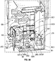
Fig. 3D is similar toFig. 3A but shows the ground switch device in its opened or ungrounded (non-conductive) state and shows the ground switch interlock device in its locked (engaged) condition or state. -
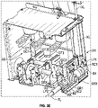
Fig. 3E is similar toFig. 3D but shows the isolator ground switch interlock device from a different perspective (and also shows the key interlock device in its locked (engaged) state). -
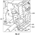
Fig. 3F in an enlarged view of the key interlock device ofFig. 3C in its locked (engaged) state. -
Fig. 4 is a partial side view of the motor control center ofFigs. 1 &2 and shows that the integrated interlock system can optionally comprise both an isolator handle linkage ground switch interlock system and a shared-key ground switch interlock system. -
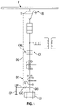
Fig. 5 is a schematic diagram that illustrates the integrated interlock system corresponding toFigs. 1 - 3F . -
Fig. 6 shows a motor control center including the integrated ground switch interlock system in accordance with an alternative embodiment of the present development. -
Fig. 1 . is a front plan view of an or motor control center M or "MCC" with certain panels and components removed for clarity, including an integrated ground switch interlock system IK according to an embodiment of the present development.Fig. 2 is an isometric view of the motor control center M. With reference to bothFig. 1 andFig. 2 , the motor control center M comprises a cabinet or enclosure E that contains power switching and power distribution components PX for powering one or more loads such as one or more motors or the like. More particularly, the MCC includes an isolation switch IS (sometimes referred to as an "isolator switch" or "isolator") used to selectively connect and disconnect (isolate) the MCC from a source of electrical power such as three-phase AC power provided via terminals T (seeFig. 5 ). - The isolator IS comprises and/or is operably connected to an isolator handle IH through which an operator manually controls the operative state of the isolation switch IS. The isolator handle IH pivots between at least a first or "off' position (typically pivoted downward a maximum extent) as shown where the isolator switch IS is opened and disconnected from the incoming power terminals T (a disconnected state) and a second or "on" position (typically pivoted upward a maximum extent) where the isolator switch IS is closed or connected to the incoming power terminals T (a connected state). The isolator handle IH is operably mechanically connected to the isolator switch IS through an isolator switch linkage ISL that opens and closes the isolator IS in response to movement of the handle IH between its first and second operative positions.
- The motor control center M further comprises a main contactor device CX that is electromechanically or otherwise operable to selectively conduct electrical power from the source terminals T to an associated motor or other load (a closed or conductive state) or to disconnect the motor or other load from the electrical power supplied by terminals T (an opened or non-conductive state). The main contactor device CX comprises a plurality of contactors corresponding in number to the number of power phases (i.e., three contactors X1,X2,X3 for three-phase power) electrically connected (when the isolator IS is closed) on an input side to the power terminals T and that are connected or adapted to be connected on an output side or "load side" to the motor(s) or other load(s) LD (
Fig. 5 ) being powered. When the main contactor CX is in its conductive state, the contactors X1-X3 are closed and conduct electrical power from the isolation switch IS to the motor(s) or other load LD. When the main contactor CX is in its non-conductive state, the contactors X1-X3 are open and interrupt the flow of electrical power from the isolation switch IS to the motor(s) or other load LD. As is generally known in the art, a contactor interlock linkage CXL is provided between the isolator handle and the main contactor device CX to ensure at least that the isolator switch IS cannot be opened or closed when the main contactor device CX is in its closed (conducting) state. - The motor control center M also comprises a ground switch or ground switch device GS that is selectively manually operable to connect the load side of the main contactor CX (i.e., the load side of the contactors X1-X3 of the main contactor CX) to a ground path GP (
Fig. 5 ) to discharge voltage from the motor control center for safety. The ground switch GS is shown separately inFigs. 3A - 3F and comprises at least one and typically a plurality of ground terminals GT (GT1-GT3), equal in number and respectively electrically connected to the load side of the contactors X1 - X3. The ground switch GS also comprises at least one and typically a plurality of ground switch contacts GC (GC1,GC2,GC3) equal in number to the ground terminals GT1-GT3. When the ground switch GS is closed (a "grounded state" as shown inFigs. 3A &3B ), the ground switch contacts GC1-GC3 contact and electrically connect respectively with the ground terminals GT1-GT3 to connect the ground terminals GT1-GT3 (and the associated contactor X1-X3 to which they are respectively connected) to the ground path GP. When the ground switch GS is opened (an "ungrounded state" as shown inFigs. 3D &3E ), the ground switch contacts GC1-GC3 separate respectively from the ground terminals GT1-GT3 to disconnect the ground terminals GT1-GT3 (and the associated contactor X1-X3 to which they are respectively connected) from the ground path GP. - With continuing reference particularly to
Figs. 3A - 3F , it can be seen that the ground switch GS comprises a rotatable ground shaft GSX that is connected to the ground path GP. The ground switch contacts GC1-GC3 are connected to and rotate with the ground shaft GSX. Rotation of the ground shaft GSX in a first angular direction moves the ground switch contacts GC1-GC3 into contact with the respective ground terminals GT1-GT3 for connection to and completion of the ground path GP. Rotation of the ground shaft GSX in an opposite, second angular direction separates the ground switch contacts GC1-GC3 from the respective ground terminals GT1-GT3 to open or interrupt the ground path GP. - The ground shaft GSX is manually rotatable using a wrench or other tool TL that is removably connected to a rotatable torque input head HX. The torque input head HX is connected to and rotates with an input gear GR1 that is drivingly engaged with the ground shaft GSX such that manually rotation of the torque input head HX in first and second directions correspondingly rotates the input gear GR 1 and also the ground shaft GSX in first and second angular directions. As shown herein the input gear GR1 is non-rotatably connected to an input shaft GR1X that is rotatably supported relative to the enclosure E, and the torque input head HX is non-rotatably connected to and/or forms a part of the input shaft GR1X. In the illustrated embodiment, a main gear GR2 such as a bevel gear is non-rotatably connected to the ground shaft GSX and is engaged with the input gear GR1 which acts as a pinion gear to drive the main gear GR2 and ground shaft GSX in the first and second angular directions to open and close the ground contacts GC1 - GC3. The ground switch device GS further comprises an output gear or driven gear GR3 that is drivingly engaged with the main gear GR2 and that rotates in first and second opposite directions in response to rotation of the main gear GR2. In particular, the driven gear GR3 rotates in opposite directions as compared to the input gear GR1 such that the driven gear GR3 rotates in second and first opposite directions when the input gear GR1 rotates in first and second directions, respectively. The gears GR1 - GR3 define a ground switch device gear train.
- The ground switch GS comprises at least one and optionally first and second interlock devices for preventing closing of the ground switch contacts GC1-GC3 when the isolator switch IS is closed and for preventing closing of the isolator switch IS when the ground switch contacts GC1-GC3 are closed. In particular, the ground switch comprises a first interlock device IX1 (sometimes referred to herein as the "isolator interlock device") and optionally also includes a second interlock device IX2 (sometimes referred to herein as the "key interlock device").
- The first (isolator) interlock device IX1 comprises a first lock base or lock block B1 that is non-rotatably connected to the driven output gear GR3. As shown, the driven output gear GR3 is non-rotatably connected to an output shaft GR3X that is rotatably supported relative to the enclosure E, and the first lock block B1 is non-rotatably connected to the output shaft GR3X so as to rotate in unison with the output gear GR3. The first lock block B1 can be non-circular and comprise a plurality of flat surfaces. The first lock block B1 comprises a first lock recess RC1.
- The first interlock device IX1 further comprises an interlock member such as an interlock member or interlock plunger LP1 that is connected to an isolation switch interlock linkage IXL that is operatively connected to the isolator switch handle IH. Due to the interlock linkage IXL, movement of the isolator switch handle IH from the first (off) position to the second (on) position induces movement of the interlock plunger LP1 in a first direction D1 toward the lock block B1 (downward in a typical installation) to a deployed or extended position as shown in
Figs. 3D &3E . Conversely, the interlock linkage IXL causes the interlock plunger LP1 to move in a second direction D2, opposite the first direction D1, away from the lock block B1 (upward in a typically installation) to a stored or retracted position when the isolator switch handle IH is moved from its second (on) position toward its first (off) position as shown inFig. 3A . - The first lock block B1 is conformed and dimensioned to block and prevent movement of the interlock plunger LP1 in the first direction D1 for all angular positions of the lock block B1 except when the lock recess RC1 is located in a select plunger receiving position where the lock recess RC1 is registered or aligned with the interlock plunger LP1. When the lock plunger LP2 is located in the first lock recess RC1, the isolator interlock device IX1 is in its "engaged" position where it prevents operation of the ground switch device GS and when the lock plunger LP2 is retracted and withdrawn from the lock recess RC1 the isolator interlock device IX1 is in its "disengaged" position where it allows operation of the ground switch device GS.
- When the isolator interlock is disengaged and moved toward its engaged position, contact between the interlock plunger LP1 and the first lock block B1 blocks movement of the lock plunger LP 1 in the first direction D1 which, in turn, blocks movement of the isolator handle to its "on" (conducting) position except when the lock recess RC1 is aligned with the lock plunger LP2. The first lock block B1 is keyed in a select angular position on the output shaft GR3X such that the lock recess RC1 is only located in the lock plunger receiving position where it is aligned with and open to receive the interlock plunger LP1 when the ground switch GS is located or arranged in its opened (non-conducting) position, i.e., when the ground contacts GC1-GC3 are open. Thus, when the lock recess RC1 is aligned with the interlock plunger LP1, the interlock plunger LP1 is able to move in the direction D1 into the lock recess RC1 (to engage the isolator interlock device IX1) which allows the isolator handle IH to move to its "on" (conducting) position. Furthermore, those of ordinary skill in the art will recognize that the lock recess RC1 is conformed and dimensioned to receive the interlock plunger LP1 therein in a manner such that, when the isolator interlock system IX1 is engaged, the interlock plunger LP1 abuts and prevents rotation of the lock block B1 and, consequently, also prevents rotation of the output gear GR3, main gear GR2, and ground shaft GSX when the interlock plunger LP1 is received and seated in the lock recess RC1. In this manner, the ground switch is restrained in its opened (non-conducting) state when the isolator handle IH is located in its second (on) position corresponding the closed (conducting) state of the isolator switch IS to prevent closing of the ground contacts GC1-GC3 when the isolator switch is in a conductive state. The interlock plunger LP1 is shown as being moved linearly in the first and second opposite directions D1,D2 by the interlock linkage IXL, but those of ordinary skill in the art will recognize that the interlock plunger can alternatively move along a non-linear path between its retracted and deployed positions.
- The second (key) interlock device IX2 similarly comprises a second lock member or lock block B2 that is non-rotatably connected to the input gear GR1. As shown, the input gear GR1 is non-rotatably connected to the input shaft GR1X that is rotatably supported relative to the enclosure E, and the lock block B2 is non-rotatably connected to the input shaft GR1X so as to be non-rotatably coupled to and rotate in unison with the input gear GR1. The second lock block B2 can be non-circular and comprise a plurality of flat surfaces. The second lock block B2 comprises a second lock recess RC2 (see
Fig. 3E &3F ). - The key interlock device IX2 further comprises an interlock member such as a keylock plunger or other lock member LP2 that is connected to a key-lock assembly LA that is operated with a removable key K. The lock assembly LA is secured to the enclosure E. When the key K is operably engaged in the lock assembly LA, rotational movement of the key K in a first direction from a first (unlocked) position to a second (locked) position induces movement of the lock member LP2 in an extension direction X1 (
Fig. 3C ) toward the lock block B2 (downward in the illustrated embodiment) to a deployed or extended or "locked" position as shown inFigs. 3E &3F . Conversely, when the key K is rotated in a second opposite direction from the second (locked) position to the first (unlocked) position, the lock assembly LA induces movement of the lock member LP2 in a retraction direction X2 (Fig. 3C ), opposite the extension direction X1, away the lock block B2 (upward in the illustrated embodiment) to a retracted or "unlocked" position as shown inFigs. 3A - 3C . The second lock block B2 is conformed and dimensioned to be contacted by and to block and prevent movement of the lock member LP2 in the extension direction X1 into its extended position for all angular positions of the second lock block B2 except when the second lock recess RC2 thereof is located in a select plunger receiving position where the recess RC2 is registered or aligned with the lock member LP2. The second lock block B2 is keyed in a select angular position on the input shaft GR1X such that the second lock recess RC2 is only located in its receiving position where it is aligned with and open to receive the lock member LP2 when the ground switch GS in in its opened (non-conducting) position, i.e., when the ground contacts GC1-GC3 are open as shown inFigs. 3E &3F Furthermore, those of ordinary skill in the art will recognize that the lock recess RC2 is conformed and dimensioned to receive the lock member LP2 therein in a manner such that the lock member LP2 abuts and prevents rotation of the second lock block B2 and, consequently, also prevents rotation of the input gear GR1, main gear GR2, and ground shaft GSX when the lock member LP2 is received and seated in the lock recess RC2. In this manner, the ground switch GS is restrained in its opened (non-conducting) state when the lock assembly LA is positioned in its locked state. The lock member LP2 is shown as being moved linearly in the first and second opposite directions XI,X2 by the lock assembly LA, but those of ordinary skill in the art will recognize that the lock member LP2 can alternatively move along a non-linear path between its retracted and extended positions. - The key K is trapped or captured in the lock assembly LA while the lock assembly LA is in its unlocked condition and can only be removed from the lock assembly LA when the lock assembly LA is in its locked condition. This allows the key K to be used in a shared-key interlock system where the same key K is used to operate first and second key interlock devices to ensure that only one of the key interlock devices is unlocked at any given time.
Fig. 4 shows that the motor control center M can include the key interlock device IX2 as described above and also includes an isolator handle key interlock device HX including a handle lock assembly HLA that selectively locks the isolator handle IH in its "off" position when locked to prevent movement of the isolator handle IH to the "on" position when locked. The handle key interlock device HX uses the same single K as the ground switch key interlock device IX2 and the key K is captured in the handle interlock device HX when it is unlocked to ensure that the isolator handle IH is moved to and locked in its "off' position before the key K can be removed from the handle interlock device HX and inserted into the ground switch key interlock device IX2 to unlock the ground switch device GS to allow the ground switch device to be moved to its conductive or "on" state. - Another advantage of a ground switch interlock system IK provided in accordance with an embodiment of the present development is that, unlike known systems, the ground switch device GS is located on the load-side of the main contactor CX, i.e., electrically between the motor or other associated load LD being powered by the motor control center M and the contactors X1-X3 of the main contactor CX. As shown in
Fig. 5 , the motor control center M is located electrically between the incoming source of electrical power P and the motor or other load LD. The isolation switch IS is selectively operable to connect or disconnect the main contactor CX from the electrical power source P. The ground switch interlock device IX1 operably interconnects the isolation switch IS and the ground switch device GS via interlock linkage IXL as described above. The isolator switch IS is electrically connected to the main contactor CX, and the main contactor CX is electrically connected on its downstream or output side to the load LD. The ground switch device GS is also located on the downstream or output side of the main contactor CX such that the ground switch contacts GC (GC1 - GC3) are electrically located between the main contactor CX and the load LD. When the ground switch contacts GC of the ground switch device GS are closed, the ground path GP is connected between the load LD and the main contactor CX to safely ground or earth the main contactor CX and the load LD. This arrangement ensures that the load side of the main contactor CX is grounded when the ground switch device GS is in its closed (conductive) state. -
Fig. 1 illustrates another main advantage of an embodiment of the present development. There, it can be seen that the ground switch contacts GC1 - GC32 are vertically aligned respectively with the ground terminals GT1 - GT3. In the case of three-phase AC power, the three ground terminals GT1 - GT3 respectively associated with the three-phases of electrical power are horizontally spaced-apart from each other in a row. Likewise, the three ground switch contacts GC1 - GC3 are horizontally spaced-apart from each other in a row and are vertically aligned respectively with the ground terminals GT1 - GT3 such that each ground terminal GT1 - GT3 lies in a common vertical reference plane with respect to its associated ground switch contact GC1 - GC3 for all operative positions of the ground switch contact GC1 - GC3. Thus, the three associated ground terminal / ground contact pairs GT1/GC1, GT2/GC2, and GT3/GC3 respectively lie in three parallel, spaced-apart vertical reference planes. This arrangement provides a simple and effective method for a human operator to quickly and safely assess the ground state (grounded or ungrounded) of each of the ground terminals GT1 - GT3 by visual inspection in that the operator will be able to determine visually whether each ground terminal GT1 - GT3 is engaged by its associated ground contact GC1 - GC3 or not by viewing the ground switch device GS from the front as shown inFig. 1 , such as through an access opening or window defined in the enclosure E. The first, second, and third ground terminals GT1 - GT3 and also the first, second, and third ground contacts GC1 - GC3 are vertically aligned with and are thus visually associated with both the first, second, and third contactors X1 - X3 and also with the first, second, and third power phases, respectively. - The physical position of the ground switch device GS relative to the main contactor CX can be altered such as by locating the ground switch device GS vertically above the main contactor CS as shown for the motor control center M' in
Fig. 6 rather than vertically below the main contactor CX as shown inFig. 1 (or the ground switch device GS can be located laterally adjacent the main contactor CX). In all cases, however, the ground switch device GS is electrically connected on the load side or output side of the main contactor CX as described above. - In the preceding specification, various embodiments have been described with reference to the accompanying drawings. It will, however, be evident that various modifications and changes may be made thereto, and additional embodiments may be implemented, without departing from the broader scope of the invention as set forth in the claims that follow. The specification and drawings are accordingly to be regarded in an illustrative rather than restrictive sense.
-
- Embodiment 1: A motor control center comprising:
- an enclosure comprising an isolation switch, a main contactor device, and a ground switch device;
- said isolation switch selectively manually operable between a connected state and a disconnected state, wherein said isolation switch in said connected state is adapted to conduct electrical power from an associated power source to said main contactor and wherein said isolation switch in said disconnected state interrupts conduction of electrical power from the associated power source to the main contactor;
- said main contactor device selectively operable between a conductive state and a non-conductive state, wherein said main contactor is adapted to electrically connect said isolation switch to said ground switch device and to an associated electrical load when said main contactor device is in its conductive state and wherein said main contactor disconnects said isolation switch from the ground switch device and the associated electrical load when said main contactor device is in its non-conductive state;
- said ground switch device manually operable from an open, ungrounded state in which said main contactor is electrically disconnected from a ground path to a closed, grounded state in which said main contactor is electrically connected to said ground path;
- said motor control center further comprising a first interlock device operably connected between said isolation switch and said ground switch device, wherein said first interlock device prevents movement of said isolation switch from said disconnected state to said connected state when said ground switch device is in said grounded state.
- Embodiment 2: The motor control center as set forth in embodiment 1, further comprising an isolation switch handle operably connected to said isolation switch and movable between an "off' position corresponding to said disconnected state of said isolation switch and an "on" position corresponding to said connected state of said isolation switch, wherein said first interlock device blocks movement of said isolation switch handle from said "off" position to said "on" position when said ground switch device is positioned in said grounded state.
- Embodiment 3: The motor control center as set forth in
embodiment 2, wherein said first interlock device prevents movement of said ground switch device from said ungrounded state to said grounded state when said isolation switch handle is located in said "on" position. - Embodiment 4: The motor control center as set forth in embodiment 3, wherein said isolation switch handle is operably connected to said isolation switch by a mechanical isolator switch linkage and wherein said first interlock device comprises a lock plunger operably connected to said isolation switch handle by an isolation switch interlock linkage.
- Embodiment 5: The motor control center as set forth in embodiment 3, wherein:
- said isolation switch interlock linkage moves said lock plunger to a retracted position when said isolation switch handle is located in its "off" position;
- said isolation switch interlock linkage moves said lock plunger to an extended position when said isolation switch handle is located in its "on" position;
- said ground switch device comprises at least one movable ground contact that moves between an opened position in said ungrounded state to a closed position in said grounded state; and
- said lock plunger blocks movement of said at least one ground contact from said opened position to said closed position when said lock plunger is in its extended position.
- Embodiment 6: The motor control center as set forth in embodiment 5, wherein said ground switch device comprises a first lock block that is contacted by said lock plunger and blocks movement of said lock plunger to its extended position when said lock plunger moves from said retracted position toward said extended position when said at least one ground contact is in its closed position.
- Embodiment 7: The motor control center as set forth in
embodiment 6, wherein said first lock block blocks movement of at least one ground contact from its opened position to its closed position when said lock plunger is in its extended position. - Embodiment 8: The motor control center as set forth in embodiment 7, wherein said first lock block comprises a first lock recess located therein, wherein said lock plunger is seated in said first lock recess when said lock plunger is in its extended position and said at least one ground contact is in its closed position.
- Embodiment 9: The motor control central as set forth in
embodiment 8, wherein said at least one ground contact is connected to a rotatable ground shaft that is electrically connected to said ground path, said ground switch device comprising a main gear connected to said ground shaft and an output gear engaged with said main gear;- wherein said first lock block is non-rotatably coupled with said output gear such that rotation of said ground shaft alters an angular position of said first lock block;
- said first lock block located in a select angular position in which said first lock recess is aligned with said lock plunger when said ground shaft is rotated to a position corresponding to said closed position of said at least one ground contact.
- Embodiment 10: The motor control center as set forth in embodiment 9, further comprising an input gear engaged with said main gear, wherein said input gear is non-rotatably connected to a torque input head that is selectively manually rotatable to rotate said input gear, said main gear, and said output gear.
- Embodiment 11: The motor control center as set forth in
embodiment 10, further comprising a first key interlock device operable by a key between a locked and an unlocked state, wherein said first key interlock blocks rotation of said input gear of said ground switch device when said first key interlock device is in its locked state. - Embodiment 12: The motor control center as set forth in
embodiment 11, further comprising a second key interlock device operable by said key between a locked and an unlocked state, wherein said second key interlock device selectively blocks movement of said isolation switch handle when said second key interlock device is in its locked state, wherein:- said key that operates said and second key interlocks is a single, common key;
- when one of the first and second key interlock devices is in its locked state the other of the first and second key interlock devices in in its unlocked state;
- said key is captured in said one of said first and second key interlock devices that is in its unlocked state such that said one of said first and second key interlock devices must be moved to its locked state before said other of said first and second key interlock devices can be moved to its unlocked state.
- Embodiment 13: The motor control center as set forth in embodiment 12, further comprising a second lock block non-rotatably coupled to said input gear, said first key interlock comprising a lock member that engages and prevents rotation of said second lock block when said lock member is in an extended position and said ground switch device is in its opened, ungrounded state.
- Embodiment 14: The motor control center as set forth in embodiment 5, said ground switch device is located on a load side of said main contactor.
- Embodiment 15: The motor control center as set forth in embodiment 14, wherein said ground switch device comprises:
- first, second, and third ground terminals electrically connected respective first, second, and third electrical phases of said main contactor;
- said at least one moveable ground contact comprises first, second, and third ground contacts that respectively contact said first, second, and third ground terminals when said first, second, and third ground contacts are in their respective closed positions.
- Embodiment 16: The motor control center as set forth in embodiment 15, wherein said first, second, and third ground terminals are respectively vertically aligned with said first, second, and third ground contacts.
- Embodiment 17: The motor control center as set forth in embodiment 16, wherein:
- said ground switch device is located vertically above or vertically below said main contactor device;
- said main contactor device comprises first, second, and third contactors electrically connected respectively to said first, second, and third ground terminals; and,
- said first, second, and third ground terminals are horizontally spaced-apart from each other in a row so that said first, second, and third ground terminals are visually associated with said first, second, and third contactors, respectively.
- Embodiment 18: An interlock system for electrical equipment, said interlock system comprising:
- an isolation switch selectively manually operable between a connected state and a disconnected state, wherein said isolation switch in said connected state is adapted to conduct electrical power and wherein said isolation switch in said disconnected state interrupts conduction of electrical power;
- a handle operably connected to said isolation switch, said handle movable between an "off" position corresponding to said disconnected state of said isolation switch and an "on" position corresponding to said connected state of said isolation switch;
- a ground switch device manually operable from an open, ungrounded state in which said main isolation switch is electrically disconnected from a ground path to a closed, grounded state in which said isolation switch is electrically connected to said ground path;
- an interlock plunger operably connected to said handle through an interlock linkage and movable to and between a retracted position corresponding to said "off" position of said handle and an extended position corresponding to said "on" position of said handle;
- said interlock plunger blocking movement of said ground switch device from said open, ungrounded state to said closed, grounded state when said interlock plunger is in its extended position.
- Embodiment 19: The interlock system as set forth in embodiment 18, wherein said ground switch device comprises a first lock block that blocks movement of said interlock plunger from said retracted position to said extended position when said ground switch device is in its closed, grounded state.
- Embodiment 20: The interlock system as set forth in embodiment 19, wherein said first lock block comprises a first recess that is aligned with and that receives said lock plunger when said lock plunger is in its extended position and said ground switch device is in its open, ungrounded state.
Claims (15)
- A motor control center comprising:an enclosure comprising an isolation switch, a main contactor device, and a ground switch device;said isolation switch selectively manually operable between a connected state and a disconnected state, wherein said isolation switch in said connected state is adapted to conduct electrical power from an associated power source to said main contactor andwherein said isolation switch in said disconnected state interrupts conduction of electrical power from the associated power source to the main contactor;said main contactor device selectively operable between a conductive state and a non-conductive state, wherein said main contactor is adapted to electrically connect said isolation switch to said ground switch device and to an associated electrical load when said main contactor device is in its conductive state and wherein said main contactor disconnects said isolation switch from the ground switch device and the associated electrical load when said main contactor device is in its non-conductive state;said ground switch device manually operable from an open, ungrounded state in which said main contactor is electrically disconnected from a ground path to a closed, grounded state in which said main contactor is electrically connected to said ground path;said motor control center further comprising a first interlock device operably connected between said isolation switch and said ground switch device, wherein said first interlock device prevents movement of said isolation switch from said disconnected state to said connected state when said ground switch device is in said grounded state.
- The motor control center as set forth in claim 1, further comprising an isolation switch handle operably connected to said isolation switch and movable between an "off" position corresponding to said disconnected state of said isolation switch and an "on" position corresponding to said connected state of said isolation switch, wherein said first interlock device blocks movement of said isolation switch handle from said "off" position to said "on" position when said ground switch device is positioned in said grounded state.
- The motor control center as set forth in claim 2, wherein said first interlock device prevents movement of said ground switch device from said ungrounded state to said grounded state when said isolation switch handle is located in said "on" position, wherein said isolation switch handle preferably is operably connected to said isolation switch by a mechanical isolator switch linkage and wherein said first interlock device comprises a lock plunger operably connected to said isolation switch handle by an isolation switch interlock linkage.
- The motor control center as set forth in claim 3, wherein:said isolation switch interlock linkage moves said lock plunger to a retracted position when said isolation switch handle is located in its "off" position;said isolation switch interlock linkage moves said lock plunger to an extended position when said isolation switch handle is located in its "on" position;said ground switch device comprises at least one movable ground contact that moves between an opened position in said ungrounded state to a closed position in said grounded state; andsaid lock plunger blocks movement of said at least one ground contact from said opened position to said closed position when said lock plunger is in its extended position.
- The motor control center as set forth in claim 4, wherein said ground switch device comprises a first lock block that is contacted by said lock plunger and blocks movement of said lock plunger to its extended position when said lock plunger moves from said retracted position toward said extended position when said at least one ground contact is in its closed position.
- The motor control center as set forth in claim 5, wherein said first lock block blocks movement of at least one ground contact from its opened position to its closed position when said lock plunger is in its extended position.
- The motor control center as set forth in claim 6, wherein said first lock block comprises a first lock recess located therein, wherein said lock plunger is seated in said first lock recess when said lock plunger is in its extended position and said at least one ground contact is in its closed position.
- The motor control central as set forth in claim 7, wherein said at least one ground contact is connected to a rotatable ground shaft that is electrically connected to said ground path, said ground switch device comprising a main gear connected to said ground shaft and an output gear engaged with said main gear;wherein said first lock block is non-rotatably coupled with said output gear such that rotation of said ground shaft alters an angular position of said first lock block;said first lock block located in a select angular position in which said first lock recess is aligned with said lock plungerwhen said ground shaft is rotated to a position corresponding to said closed position of said at least one ground contact.
- The motor control center as set forth in claim 8, further comprising an input gear engaged with said main gear, wherein said input gear is non-rotatably connected to a torque input head that is selectively manually rotatable to rotate said input gear, said main gear, and said output gear.
- The motor control center as set forth in claim 9, further comprising a first key interlock device operable by a key between a locked and an unlocked state, wherein said first key interlock blocks rotation of said input gear of said ground switch device when said first key interlock device is in its locked state.
- The motor control center as set forth in claim 10, further comprising a second key interlock device operable by said key between a locked and an unlocked state, wherein said second key interlock device selectively blocks movement of said isolation switch handle when said second key interlock device is in its locked state, wherein:said key that operates said and second key interlocks is a single, common key;when one of the first and second key interlock devices is in its locked state the other of the first and second key interlock devices in in its unlocked state;said key is captured in said one of said first and second key interlock devices that is in its unlocked state such that said one of said first and second key interlock devices must be moved to its locked state before said other of said first and second key interlock devices can be moved to its unlocked state, the motor control center preferably further comprising a second lock block non-rotatably coupled to said input gear, said first key interlock comprising a lock member that engages and prevents rotation of said second lock block when said lock member is in an extended position and said ground switch device is in its opened, ungrounded state.
- The motor control center as set forth in claim 4, said ground switch device is located on a load side of said main contactor.
- The motor control center as set forth in claim 12, wherein said ground switch device comprises:first, second, and third ground terminals electrically connected respective first, second, andthird electrical phases of said main contactor;said at least one moveable ground contact comprises first, second, and third ground contacts that respectively contact said first, second, and third ground terminals when said first, second, and third ground contacts are in their respective closed positions, wherein preferably:
said first, second, and third ground terminals are respectively vertically aligned with said first, second, and third ground contacts, and wherein:said ground switch device is located vertically above or vertically below said main contactor device;said main contactor device comprises first, second, and third contactors electrically connected respectively to said first, second, and third ground terminals; and,said first, second, and third ground terminals are horizontally spaced-apart from each other in a row so that said first, second, and third ground terminals are visually associated with said first, second, and third contactors, respectively. - An interlock system for electrical equipment, said interlock system comprising:an isolation switch selectively manually operable between a connected state and a disconnected state, wherein said isolation switch in said connected state is adapted to conduct electrical power and wherein said isolation switch in said disconnected state interrupts conduction of electrical power;a handle operably connected to said isolation switch, said handle movable between an "off" position corresponding to said disconnected state of said isolation switch and an "on" position corresponding to said connected state of said isolation switch;a ground switch device manually operable from an open, ungrounded state in which said main isolation switch is electrically disconnected from a ground path to a closed, grounded state in which said isolation switch is electrically connected to said ground path;an interlock plunger operably connected to said handle through an interlock linkage andmovable to and between a retracted position corresponding to said "off" position of said handle and an extended position corresponding to said "on" position of said handle;said interlock plunger blocking movement of said ground switch device from said open,ungrounded state to said closed, grounded state when said interlock plunger is in its extended position.
- The interlock system as set forth in claim 14, wherein said ground switch device comprises a first lock block that blocks movement of said interlock plunger from said retracted position to said extended position when said ground switch device is in its closed, grounded state, wherein said first lock block preferably comprises a first recess that is aligned with and that receives said lock plunger when said lock plunger is in its extended position and said ground switch device is in its open, ungrounded state.
Applications Claiming Priority (1)
| Application Number | Priority Date | Filing Date | Title |
|---|---|---|---|
| US17/237,744 US11476647B1 (en) | 2021-04-22 | 2021-04-22 | Maintenance grounding device in motor control center with integrated interlock system |
Publications (1)
| Publication Number | Publication Date |
|---|---|
| EP4080699A1 true EP4080699A1 (en) | 2022-10-26 |
Family
ID=81326288
Family Applications (1)
| Application Number | Title | Priority Date | Filing Date |
|---|---|---|---|
| EP22168790.8A Pending EP4080699A1 (en) | 2021-04-22 | 2022-04-19 | Maintenance grounding device in motor control center with integrated interlock system |
Country Status (3)
| Country | Link |
|---|---|
| US (2) | US11476647B1 (en) |
| EP (1) | EP4080699A1 (en) |
| CN (1) | CN115241743B (en) |
Cited By (1)
| Publication number | Priority date | Publication date | Assignee | Title |
|---|---|---|---|---|
| CN121034882A (en) * | 2025-10-31 | 2025-11-28 | 大连北方真空开关有限公司 | Electric isolation grounding mechanism |
Families Citing this family (5)
| Publication number | Priority date | Publication date | Assignee | Title |
|---|---|---|---|---|
| US11782083B2 (en) * | 2021-04-22 | 2023-10-10 | ESDEMC Technology LLC | Relay pogo charged device model tester using electrostatic discharge method and structure for repeatable charged device model testing |
| US11476647B1 (en) * | 2021-04-22 | 2022-10-18 | Rockwell Automation Technologies, Inc. | Maintenance grounding device in motor control center with integrated interlock system |
| CN115547712B (en) * | 2022-12-01 | 2023-02-21 | 宁波天安智能电网科技股份有限公司 | A joint-driven operating mechanism and isolating combined circuit breaker |
| CN118486101A (en) * | 2024-04-08 | 2024-08-13 | 四川汉舟电气股份有限公司 | Control method and system for power supply and power failure linkage between upper and lower electrical cabinets |
| DE102024205325A1 (en) * | 2024-06-10 | 2025-12-11 | Siemens Energy Global GmbH & Co. KG | Grounding a current path in a switchgear |
Citations (3)
| Publication number | Priority date | Publication date | Assignee | Title |
|---|---|---|---|---|
| CZ6336U1 (en) * | 1997-05-29 | 1997-07-10 | Serw S.R.O. | Blocking mechanism of isolators with grounding switches |
| US6329615B1 (en) * | 1998-12-18 | 2001-12-11 | Alstom | Device for interlocking the manual actuation of a switch with the help of locks |
| US20090141430A1 (en) * | 2006-05-29 | 2009-06-04 | Siemens Aktiengesellschaft | Gas-Insulated Switchpanel of a Medium-Voltage Switchgear Assembly |
Family Cites Families (70)
| Publication number | Priority date | Publication date | Assignee | Title |
|---|---|---|---|---|
| US2358146A (en) * | 1942-11-20 | 1944-09-12 | Gen Electric | Operating mechanism |
| US2364974A (en) * | 1943-04-05 | 1944-12-12 | Gen Electric | Switchgear |
| US3206567A (en) * | 1961-06-13 | 1965-09-14 | Smith Corp A O | Key controlled switch arrangement |
| FR2036911B1 (en) * | 1969-04-17 | 1976-04-16 | Saparel | |
| NL133619C (en) * | 1969-08-04 | |||
| GB1379895A (en) * | 1970-12-22 | 1975-01-08 | Drayton Controls Ltd | Electric switch controls |
| EP0008513A1 (en) * | 1978-08-18 | 1980-03-05 | George Caton | Switch arrangement for three-phase electrical supply |
| US4286242A (en) * | 1979-09-17 | 1981-08-25 | Westinghouse Electric Corp. | Mechanical interlock for low voltage circuit breakers |
| JPH0734339B2 (en) * | 1989-03-17 | 1995-04-12 | 新晃電機株式会社 | Interlock device for push button switch |
| FR2660109B1 (en) * | 1990-03-23 | 1992-06-05 | Merlin Gerin | CONTROL MECHANISM OF A THREE-POSITION SWITCH. |
| CA2054292A1 (en) * | 1991-10-25 | 1993-04-26 | James Bertram Baragar | Transformer connector |
| US5341036A (en) * | 1991-12-11 | 1994-08-23 | Square D Company | Two hand operated machine control station using capacitive proximity switches |
| DE19511168A1 (en) * | 1995-03-28 | 1996-10-02 | Abb Management Ag | Switching device |
| DE29904223U1 (en) * | 1999-02-24 | 1999-06-02 | Siemens AG, 80333 München | Drive device for a switching device, in particular for earthing switches of medium-voltage switchgear |
| JP4130735B2 (en) * | 2001-12-12 | 2008-08-06 | 株式会社日立製作所 | Switchgear and receiving / transforming equipment using the same |
| US6727442B2 (en) * | 2001-12-21 | 2004-04-27 | Square D Company | Medium voltage motor control center load discharge device |
| US6512669B1 (en) * | 2001-12-21 | 2003-01-28 | Square D Company | Medium voltage motor control center instrument compartment |
| US7140702B2 (en) * | 2001-12-21 | 2006-11-28 | Square D Company | Medium voltage motor control center arc resistant enclosure |
| CA2397024C (en) * | 2002-08-07 | 2008-02-19 | Edward M. Turley | Switch mechanism for reversible grinder |
| EP1538650B1 (en) * | 2003-12-02 | 2017-11-08 | Schneider Electric Energy Manufacturing Italia S.r.l. | Isolator/circuit-breaker device for electric substations |
| CA2521677C (en) * | 2004-10-01 | 2013-01-22 | Eaton Corporation | Actuator for auxiliary switch and circuit breaker incorporating the same |
| DE102004061358B4 (en) * | 2004-12-21 | 2012-07-05 | Abb Technology Ag | High-voltage switchgear |
| US7449645B1 (en) * | 2005-11-01 | 2008-11-11 | Reliance Controls Corporation | Neutral bracket apparatus for an electrical panel |
| US7462791B1 (en) * | 2006-04-14 | 2008-12-09 | Reliance Controls Corporation | Interlock assembly for sequentially actuating power supply switches including a neutrally connected switch |
| DE102006024007A1 (en) * | 2006-05-23 | 2007-11-29 | Abb Technology Ag | Switching device for an electrical switchgear for power distribution |
| US7429708B1 (en) * | 2007-06-22 | 2008-09-30 | Eja, Limited | Safety switch |
| CN201174507Y (en) * | 2008-03-28 | 2008-12-31 | 江苏金华厦电气有限公司 | Switch cabinet grounding switch locking apparatus |
| JP5367594B2 (en) * | 2010-01-13 | 2013-12-11 | 株式会社東芝 | Switch operating device |
| US9136077B2 (en) * | 2011-04-14 | 2015-09-15 | Impact Power, Inc. | Three-phase, multi-way vacuum interrupter switchgear with internal ground switches |
| KR101690132B1 (en) * | 2012-11-05 | 2016-12-27 | 엘에스산전 주식회사 | Interlock device for gas insulation switchgear |
| CN103166143B (en) * | 2012-12-24 | 2015-12-09 | 宁波优维电力科技有限公司 | A kind of solid insulation ring main unit |
| CN203871215U (en) * | 2014-04-25 | 2014-10-08 | 浙江高压开关厂有限公司 | Five-prevention interlocking device of high-voltage ring main unit |
| CN104319163B (en) * | 2014-11-05 | 2016-11-30 | 湖州电力设备成套有限公司 | A kind of vacuum circuit breaker |
| CN104319164B (en) * | 2014-11-05 | 2016-07-13 | 湖州电力设备成套有限公司 | A kind of vacuum load switch |
| CN104319131B (en) * | 2014-11-05 | 2016-03-23 | 湖州电力设备成套有限公司 | A kind of interlocking mechanism of switch cabinet |
| CN104319132B (en) * | 2014-11-05 | 2016-08-17 | 湖州电力设备成套有限公司 | A kind of switch cubicle operating mechanism |
| RU2669918C1 (en) * | 2015-01-28 | 2018-10-17 | Абб Швайц Аг | Mechanical interlocking unit for disconnector and grounding switch |
| CN104681347B (en) * | 2015-03-10 | 2017-08-25 | 埃尔凯电器(珠海)有限公司 | Operating mechanism and the high-voltage switch gear with the operating mechanism |
| CN105140064A (en) * | 2015-07-29 | 2015-12-09 | 国家电网公司 | Interlocking device for isolation switch, earthing switch and circuit breaker |
| CN205248144U (en) * | 2015-11-25 | 2016-05-18 | 川力电气有限公司 | Novel keep apart and ground connection formula interlock mechanism |
| CN105406386B (en) * | 2015-12-03 | 2018-07-10 | 平高集团有限公司 | The interlock of valve and earthing switch |
| CN105470036B (en) * | 2015-12-22 | 2018-01-19 | 广州白云电器设备股份有限公司 | A kind of station operating mechanism of diplopore three for high pressure GIS three-stations |
| CN106531500A (en) * | 2015-12-31 | 2017-03-22 | 重庆市纳楠斯机械设备有限公司 | High-voltage isolation switch cabinet provided with operating mechanism |
| CN105742091B (en) * | 2016-03-27 | 2017-10-17 | 梁作鹏 | Five-prevention interlocking operation mechanism of switch cabinet |
| US10931140B2 (en) * | 2016-05-05 | 2021-02-23 | Onesubsea Ip Uk Limited | Supply of auxiliary power to remote installations |
| CN106024453B (en) * | 2016-06-22 | 2018-06-26 | 四川电器集团股份有限公司 | A kind of interlock for preventing maloperation |
| US10108238B2 (en) * | 2016-07-22 | 2018-10-23 | Rockwell Automation Technologies, Inc. | Intelligent power tap for providing power and communicating in industrial automation applications |
| CN106098436A (en) * | 2016-08-12 | 2016-11-09 | 北京杰远电气有限公司 | Station interlock for switch cubicle |
| CN106548885B (en) * | 2016-10-26 | 2019-03-26 | 南方电网科学研究院有限责任公司 | An isolating switch and grounding switch indicating device for nitrogen switchgear |
| CN106449233B (en) * | 2016-11-16 | 2018-06-01 | 协成科技股份有限公司 | The three axis interlocks and its operating method of high voltage load switch |
| CN106449234A (en) * | 2016-12-23 | 2017-02-22 | 福建逢兴机电设备有限公司 | Breaker combined electric appliance |
| CN109256289B (en) * | 2017-07-14 | 2022-04-29 | Abb瑞士股份有限公司 | Lock assembly for switchgear of an electric power distribution system |
| CN107507716B (en) * | 2017-07-26 | 2019-07-09 | 安徽驰纬电气有限公司 | A kind of looped network cabinet switch interlock |
| CN107785207A (en) * | 2017-10-27 | 2018-03-09 | 成都亨通兆业精密机械有限公司 | A kind of high voltage isolator and grounding switch operation interlocking mechanism |
| CN107665783B (en) * | 2017-11-20 | 2019-04-23 | 北京合纵科技股份有限公司 | Lower isolation ring main unit interlocking device |
| CN107808788B (en) * | 2017-12-08 | 2020-01-31 | 西门子中压开关技术(无锡)有限公司 | Interlocking device and assembly of switch cabinet and switch cabinet |
| CN108376628B (en) * | 2018-04-13 | 2025-04-11 | 浙江恒控电气有限公司 | A multifunctional combined vacuum circuit breaker |
| CN108461332B (en) * | 2018-04-13 | 2025-01-07 | 浙江恒控电气有限公司 | Interlocking mechanism between circuit breaker, disconnector and earthing switch |
| CN108511256A (en) * | 2018-05-14 | 2018-09-07 | 河南森源电气股份有限公司 | Earthing switch interlocking mechanism and switchgear |
| CN108831779B (en) * | 2018-08-21 | 2024-05-07 | 广东省江门市新会电气控制设备厂有限公司 | A vacuum load switch cabinet interlocking device |
| CN109216065B (en) * | 2018-08-22 | 2020-06-19 | 深圳供电局有限公司 | Electromagnetic locking device for knife operating hole in ring network cabinet |
| US10720765B2 (en) * | 2018-09-17 | 2020-07-21 | Rockwell Automation Technologies, Inc. | System for isolating power conductors using slidable insulating sheets |
| CN111091998B (en) * | 2018-10-23 | 2022-06-28 | 福建工程学院 | Outdoor miniaturized high voltage AC isolation series linkage vacuum circuit breaker |
| CN109524257B (en) * | 2018-12-29 | 2023-08-29 | 宁波天安智能电网科技股份有限公司 | An interlocking mechanism of an integrated switch mechanism |
| CN110211826B (en) * | 2019-04-26 | 2024-05-24 | 新机电器有限公司 | Interlocking mechanism in load switch |
| CN110911191B (en) * | 2019-11-29 | 2021-09-03 | 北京双杰电气股份有限公司 | Rear forced interlocking mechanism of vacuum cabinet |
| CN111192775B (en) * | 2019-12-20 | 2021-10-29 | 天津平高智能电气有限公司 | Switchgear and its locking and interlocking device |
| CN111146026B (en) * | 2020-01-20 | 2025-06-10 | 珠海欧力配网自动化股份有限公司 | Gas-insulated ring main unit interlocking device |
| CN111162461B (en) * | 2020-01-20 | 2025-07-15 | 珠海欧力配网自动化股份有限公司 | 10kV environmentally friendly gas insulated ring main unit |
| US11476647B1 (en) * | 2021-04-22 | 2022-10-18 | Rockwell Automation Technologies, Inc. | Maintenance grounding device in motor control center with integrated interlock system |
-
2021
- 2021-04-22 US US17/237,744 patent/US11476647B1/en active Active
-
2022
- 2022-04-19 EP EP22168790.8A patent/EP4080699A1/en active Pending
- 2022-04-20 CN CN202210415406.0A patent/CN115241743B/en active Active
- 2022-10-17 US US17/967,742 patent/US11984289B2/en active Active
Patent Citations (3)
| Publication number | Priority date | Publication date | Assignee | Title |
|---|---|---|---|---|
| CZ6336U1 (en) * | 1997-05-29 | 1997-07-10 | Serw S.R.O. | Blocking mechanism of isolators with grounding switches |
| US6329615B1 (en) * | 1998-12-18 | 2001-12-11 | Alstom | Device for interlocking the manual actuation of a switch with the help of locks |
| US20090141430A1 (en) * | 2006-05-29 | 2009-06-04 | Siemens Aktiengesellschaft | Gas-Insulated Switchpanel of a Medium-Voltage Switchgear Assembly |
Non-Patent Citations (3)
| Title |
|---|
| ABB: "UniGear type ZS1", 30 April 2004 (2004-04-30), XP055322812, Retrieved from the Internet <URL:http://www.elecom.vn/Uploads/files/UnigearZS1.pdf> [retrieved on 20161124] * |
| ANONYMOUS: "Adding additional layers of personnel safety to UL 347 Motor Control Centers", ALLEN-BRADLEY, 1 January 2021 (2021-01-01), XP055937870, Retrieved from the Internet <URL:https://literature.rockwellautomation.com/idc/groups/literature/documents/wp/mcc-wp003_-en-p.pdf> [retrieved on 20220704] * |
| ANONYMOUS: "CENTERLINE 400 A One-High Cabinet, Standard and Arc-Resistant Enclosure", 1 January 2021 (2021-01-01), XP055937881, Retrieved from the Internet <URL:https://literature.rockwellautomation.com/idc/groups/literature/documents/um/1512a-um100_-en-p.pdf> [retrieved on 20220704] * |
Cited By (1)
| Publication number | Priority date | Publication date | Assignee | Title |
|---|---|---|---|---|
| CN121034882A (en) * | 2025-10-31 | 2025-11-28 | 大连北方真空开关有限公司 | Electric isolation grounding mechanism |
Also Published As
| Publication number | Publication date |
|---|---|
| CN115241743A (en) | 2022-10-25 |
| US20230043360A1 (en) | 2023-02-09 |
| CN115241743B (en) | 2025-01-10 |
| US11476647B1 (en) | 2022-10-18 |
| US11984289B2 (en) | 2024-05-14 |
| US20220344913A1 (en) | 2022-10-27 |
Similar Documents
| Publication | Publication Date | Title |
|---|---|---|
| US11984289B2 (en) | Maintenance grounding device in motor control center with integrated interlock system | |
| US6777627B1 (en) | Remote control and racking device for medium-voltage circuit breakers | |
| US9466965B2 (en) | Motor control center unit withdraw with door closed | |
| US20120127635A1 (en) | Modular Pump Control Panel Assembly | |
| CN105406386B (en) | The interlock of valve and earthing switch | |
| US20160241114A1 (en) | Method of connecting and disconnecting power to loads and a switching apparatus employing same | |
| US20250030235A1 (en) | Electrical power distribution systems with a bypass unit that couples to a load and electrically engages one of two alternate units for powering the load and related methods | |
| US9275807B2 (en) | Interlock system for switchgear | |
| CN104810174B (en) | Switch cabinet circuit breaker closing knob locking device and switch cabinet group | |
| US7277294B2 (en) | Contactor draw out tray | |
| US20250343399A1 (en) | Electrical power distribution systems with a bypass unit that couples to a load and electrically engages one of two alternate units for powering the load and related methods | |
| KR20160141575A (en) | Three position mechanism of gas insulated switchgear | |
| CN108074774B (en) | Cam selector for earthing switch | |
| EP3913648A1 (en) | Apparatus for operating electric switching device | |
| US9756748B1 (en) | Removable rack mountable power cell | |
| CN107465111B (en) | distribution board | |
| CN206301707U (en) | A high-voltage switchgear with isolating switch and interlocking parts | |
| CN110504637B (en) | Interlocking protection method for high voltage remote power supply equipment | |
| CN115483565A (en) | Bus tap unit | |
| US2660694A (en) | Housed capacitor assembly with interlocked grounding switch | |
| CN120600565B (en) | An automatic disconnection device for grounding switch in an electrical switchgear | |
| CN111697475A (en) | Anti-misoperation device of high-voltage board | |
| CN204178969U (en) | Back door of high-tension switch cubicle blocking mechanism | |
| CN117374762A (en) | Rotary operating mechanism of switch cabinet | |
| RU193987U1 (en) | Switchgear compartment of an electrical device |
Legal Events
| Date | Code | Title | Description |
|---|---|---|---|
| PUAI | Public reference made under article 153(3) epc to a published international application that has entered the european phase |
Free format text: ORIGINAL CODE: 0009012 |
|
| STAA | Information on the status of an ep patent application or granted ep patent |
Free format text: STATUS: THE APPLICATION HAS BEEN PUBLISHED |
|
| AK | Designated contracting states |
Kind code of ref document: A1 Designated state(s): AL AT BE BG CH CY CZ DE DK EE ES FI FR GB GR HR HU IE IS IT LI LT LU LV MC MK MT NL NO PL PT RO RS SE SI SK SM TR |
|
| STAA | Information on the status of an ep patent application or granted ep patent |
Free format text: STATUS: REQUEST FOR EXAMINATION WAS MADE |
|
| 17P | Request for examination filed |
Effective date: 20230125 |
|
| RBV | Designated contracting states (corrected) |
Designated state(s): AL AT BE BG CH CY CZ DE DK EE ES FI FR GB GR HR HU IE IS IT LI LT LU LV MC MK MT NL NO PL PT RO RS SE SI SK SM TR |
|
| STAA | Information on the status of an ep patent application or granted ep patent |
Free format text: STATUS: EXAMINATION IS IN PROGRESS |
|
| 17Q | First examination report despatched |
Effective date: 20241223 |