EP4080670A1 - Cylindrical battery - Google Patents
Cylindrical battery Download PDFInfo
- Publication number
- EP4080670A1 EP4080670A1 EP20901542.9A EP20901542A EP4080670A1 EP 4080670 A1 EP4080670 A1 EP 4080670A1 EP 20901542 A EP20901542 A EP 20901542A EP 4080670 A1 EP4080670 A1 EP 4080670A1
- Authority
- EP
- European Patent Office
- Prior art keywords
- metal component
- resin component
- exterior
- battery
- end plate
- Prior art date
- Legal status (The legal status is an assumption and is not a legal conclusion. Google has not performed a legal analysis and makes no representation as to the accuracy of the status listed.)
- Pending
Links
Images
Classifications
-
- H—ELECTRICITY
- H01—ELECTRIC ELEMENTS
- H01M—PROCESSES OR MEANS, e.g. BATTERIES, FOR THE DIRECT CONVERSION OF CHEMICAL ENERGY INTO ELECTRICAL ENERGY
- H01M50/00—Constructional details or processes of manufacture of the non-active parts of electrochemical cells other than fuel cells, e.g. hybrid cells
- H01M50/10—Primary casings; Jackets or wrappings
- H01M50/102—Primary casings; Jackets or wrappings characterised by their shape or physical structure
- H01M50/107—Primary casings; Jackets or wrappings characterised by their shape or physical structure having curved cross-section, e.g. round or elliptic
-
- H—ELECTRICITY
- H01—ELECTRIC ELEMENTS
- H01M—PROCESSES OR MEANS, e.g. BATTERIES, FOR THE DIRECT CONVERSION OF CHEMICAL ENERGY INTO ELECTRICAL ENERGY
- H01M50/00—Constructional details or processes of manufacture of the non-active parts of electrochemical cells other than fuel cells, e.g. hybrid cells
- H01M50/10—Primary casings; Jackets or wrappings
- H01M50/183—Sealing members
- H01M50/184—Sealing members characterised by their shape or structure
-
- H—ELECTRICITY
- H01—ELECTRIC ELEMENTS
- H01M—PROCESSES OR MEANS, e.g. BATTERIES, FOR THE DIRECT CONVERSION OF CHEMICAL ENERGY INTO ELECTRICAL ENERGY
- H01M50/00—Constructional details or processes of manufacture of the non-active parts of electrochemical cells other than fuel cells, e.g. hybrid cells
- H01M50/10—Primary casings; Jackets or wrappings
- H01M50/183—Sealing members
- H01M50/186—Sealing members characterised by the disposition of the sealing members
- H01M50/188—Sealing members characterised by the disposition of the sealing members the sealing members being arranged between the lid and terminal
-
- H—ELECTRICITY
- H01—ELECTRIC ELEMENTS
- H01M—PROCESSES OR MEANS, e.g. BATTERIES, FOR THE DIRECT CONVERSION OF CHEMICAL ENERGY INTO ELECTRICAL ENERGY
- H01M50/00—Constructional details or processes of manufacture of the non-active parts of electrochemical cells other than fuel cells, e.g. hybrid cells
- H01M50/30—Arrangements for facilitating escape of gases
- H01M50/342—Non-re-sealable arrangements
-
- H—ELECTRICITY
- H01—ELECTRIC ELEMENTS
- H01M—PROCESSES OR MEANS, e.g. BATTERIES, FOR THE DIRECT CONVERSION OF CHEMICAL ENERGY INTO ELECTRICAL ENERGY
- H01M50/00—Constructional details or processes of manufacture of the non-active parts of electrochemical cells other than fuel cells, e.g. hybrid cells
- H01M50/50—Current conducting connections for cells or batteries
- H01M50/531—Electrode connections inside a battery casing
- H01M50/54—Connection of several leads or tabs of plate-like electrode stacks, e.g. electrode pole straps or bridges
-
- H—ELECTRICITY
- H01—ELECTRIC ELEMENTS
- H01M—PROCESSES OR MEANS, e.g. BATTERIES, FOR THE DIRECT CONVERSION OF CHEMICAL ENERGY INTO ELECTRICAL ENERGY
- H01M50/00—Constructional details or processes of manufacture of the non-active parts of electrochemical cells other than fuel cells, e.g. hybrid cells
- H01M50/50—Current conducting connections for cells or batteries
- H01M50/543—Terminals
- H01M50/552—Terminals characterised by their shape
- H01M50/559—Terminals adapted for cells having curved cross-section, e.g. round, elliptic or button cells
-
- H—ELECTRICITY
- H01—ELECTRIC ELEMENTS
- H01M—PROCESSES OR MEANS, e.g. BATTERIES, FOR THE DIRECT CONVERSION OF CHEMICAL ENERGY INTO ELECTRICAL ENERGY
- H01M50/00—Constructional details or processes of manufacture of the non-active parts of electrochemical cells other than fuel cells, e.g. hybrid cells
- H01M50/50—Current conducting connections for cells or batteries
- H01M50/572—Means for preventing undesired use or discharge
- H01M50/574—Devices or arrangements for the interruption of current
- H01M50/578—Devices or arrangements for the interruption of current in response to pressure
-
- Y—GENERAL TAGGING OF NEW TECHNOLOGICAL DEVELOPMENTS; GENERAL TAGGING OF CROSS-SECTIONAL TECHNOLOGIES SPANNING OVER SEVERAL SECTIONS OF THE IPC; TECHNICAL SUBJECTS COVERED BY FORMER USPC CROSS-REFERENCE ART COLLECTIONS [XRACs] AND DIGESTS
- Y02—TECHNOLOGIES OR APPLICATIONS FOR MITIGATION OR ADAPTATION AGAINST CLIMATE CHANGE
- Y02E—REDUCTION OF GREENHOUSE GAS [GHG] EMISSIONS, RELATED TO ENERGY GENERATION, TRANSMISSION OR DISTRIBUTION
- Y02E60/00—Enabling technologies; Technologies with a potential or indirect contribution to GHG emissions mitigation
- Y02E60/10—Energy storage using batteries
Definitions
- the present disclosure relates to a cylindrical battery.
- a secondary battery In recent years, there has been a need for a secondary battery to have a further increased capacity because applications have been expanding to a power source for electric vehicles, a power storage device for utilizing natural energy, and the like.
- a battery module In electric vehicle and power storage devices, a battery module is used, which is formed by connecting a number of secondary batteries in series or in parallel via an external lead. As the capacity of the secondary battery increases, higher safety is required for the secondary battery and the battery module.
- a battery internal pressure is abnormally increased due to overcharge of the secondary battery, for example, a current path in the secondary battery is caused to be interrupted to prevent thermal runaway and rupture of the secondary battery in advance.
- Patent Literature 1 describes a cylindrical battery in which a current interruption mechanism is incorporated into a sealing member that seals one end of an exterior can to ensure safety.
- the current interruption mechanism is configured by combining a valve member made of a metal, an insulating member, and a metal body having a ventilation hole. Respective central portions of the valve member and the metal body are connected to each other, and the insulating member is interposed between their respective outer peripheral portions.
- the metal body pulls a connection part with the valve member outward of the battery, and the connection part or a thin portion provided in the metal body is fractured so that a current path between the valve member and the metal body is interrupted. Further, when the battery internal pressure increases, the valve member is fractured with the thin portion of the valve member used as a starting point, whereby a gas in the battery is exhausted.
- the sealing member that closes the one end of the exterior can includes three components, i.e., the valve member, the insulating member, and the metal body to make the sealing member have a current interruption function. Since the components are required to reliably operate at the time of an abnormality in the battery, it is essential that each have a complicated and highly accurate processed shape. As the number of components constituting the sealing member increases, like in the configuration described in Patent Literature 1, this places a large burden such as an increase in the number of man-hours in processing. Thus, it is desired to reduce the number of components constituting the sealing member.
- a cylindrical battery according to the present disclosure comprises an exterior can having a bottomed cylindrical shape, a sealing member that closes one end of the exterior can, an electrode assembly arranged in the exterior can, and a resin component having electrical insulation disposed between the exterior can and the sealing member, wherein the sealing member includes a metal component electrically connected to an electrode lead led out from the electrode assembly, the metal component includes an easy fracture part radially inside a connection part between the metal component and the electrode lead, and is caulked and fixed by the exterior can with the resin component interposed therebetween, and the resin component is caulked and fixed by the metal component more radially inside the metal component than the easy fracture part.
- the cylindrical battery according to present disclosure makes it possible to reduce the number of components constituting the sealing member because it is capable of making the metal component constituting the sealing member have a current interruption function.
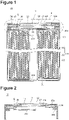
- FIG. 1 is a sectional view of a cylindrical battery 10 according to the embodiment.
- a non-aqueous electrolyte secondary battery such as a lithium ion battery is used for the cylindrical battery 10.
- the cylindrical battery 10 is configured by housing an electrode assembly 20 and a non-aqueous electrolyte (not illustrated) in a substantially cylindrical exterior can 100 having a bottomed cylindrical shape.
- a sealing member 11 is fixed to an opening at one end (an upper end in FIG. 1 ) of the exterior can 100 with a resin component 18 having electrical insulation interposed therebetween.
- the opening at the one end of the exterior can 100 is closed by the sealing member 11 with the resin component 18 interposed therebetween.
- the resin component 18 is an insulating member, and has a function as a gasket that seals a space between the exterior can 100 and the sealing member 11, and also has a function of exhausting a gas when a battery internal pressure increases, as described below.
- the non-aqueous electrolyte contains a non-aqueous solvent and an electrolyte salt dissolved in the non-aqueous solvent.
- the non-aqueous electrolyte is not limited to a liquid electrolyte, and may be a solid electrolyte using a gel polymer or the like.
- the electrode assembly 20 is of a wound type, includes a positive electrode plate 21, a negative electrode plate 22, and a separator 23, and is obtained by winding the positive electrode plate 21 and the negative electrode plate 22 in a spiral shape with the separator 23 interposed therebetween.
- one side in a winding axis direction of the electrode assembly 20 and the other side in the winding axis direction may be respectively referred to as “upper” and “lower”.
- the sealing member 11 is composed of only a metal component 12.
- the metal component 12 has a function as a positive electrode terminal and a function as a current interruption function for interrupting a current path when the battery internal pressure increases.
- the metal component 12 includes a disk-shaped outer end plate portion 13 disposed at an outer end of the battery, a disk-shaped inner end plate portion 15 disposed at an inner end of the battery, and a disk-shaped connection part 17 that connects the outer end plate portion 13 and the inner end plate portion 15 to each other.
- the outer diameter of the outer end plate portion 13 is smaller than the outer diameter of the inner end plate portion 15.
- the outer diameter of the connection part 17 is smaller than the respective outer diameters of the outer end plate portion 13 and the inner end plate portion 15.
- the outer end plate portion 13, the inner end plate portion 15, and the connection part 17 are coaxial such that their respective center axes match one another.
- a circular groove portion 12a is formed between the outer end plate portion 13 and the inner end plate portion 15 of the metal component 12, and a flange portion 15a is formed radially outside the connection part 17 as part of the inner end plate portion 15.
- the metal component 12 can be produced by aluminum or an aluminum alloy, for example.
- An external lead (not illustrated) to be electrically connected to another cylindrical battery in a battery module (not illustrated) is bonded by welding to an outer surface (an upper surface in FIG. 1 ) of an external terminal composed of the outer end plate portion 13.
- the flange portion 15a includes an easy fracture part 16 radially inside a connection part G between the metal component 12 and the positive electrode lead 21a.
- the easy fracture part 16 is an annular thin portion formed in a portion in the radial direction of the flange portion 15a, and the easy fracture part 16 is formed once a circularly annular groove 15b is formed in a portion in the radial direction of an inner side surface (a lower side surface in FIG. 1 ) of the flange portion 15a.
- the easy fracture part 16 can also be formed on an outer side surface (an upper side surface in FIG. 1 ) of the flange portion 15a.
- the resin component 18 is disposed between an inner peripheral surface of the opening formed at the one end (the upper end in FIG. 1 ) of the exterior can 100 and an outer peripheral surface of the sealing member 11.
- a portion in a circumferential direction of the resin component 18 has a substantially J shape in cross section, whose battery outer side end portion (an upper end portion in FIG. 1 ) is longer than its battery inner side end portion (a lower end portion in FIG. 1 ), and its entirety is formed into an annular shape in a planar view.
- the flange portion 15a of the inner end plate portion 15 is caulked and fixed by the exterior can 100 with the resin component 18 interposed therebetween.
- the resin component 18 is held in a compressed state between the one end of the exterior can 100 and the outer peripheral surface of the sealing member 11, and is caulked and fixed by the metal component 12 more radially inside the metal component 12 than the easy fracture part 16.
- a distal end portion of the resin component 18 extending from between the flange portion 15a and the one end of the exterior can 100 is caulked and fixed by the outer end plate portion 13 and the inner end plate portion 15.
- a sealing structure is formed between the distal end portion of the resin component 18 and the sealing member 11.
- a material that ensures electrical insulation and does not affect a battery characteristic can be used for the resin component 18.
- Polymer resin is preferable as a material for the resin component 18, and examples thereof include polypropylene (PP) resin and polybutylene terephthalate (PBT) resin.
- the sealing property in the battery is also ensured after the easy fracture part 16 is fractured due to the increase in the battery internal pressure.
- the resin component 18 is deformed to the outside of the battery so that a portion including the outer end plate portion 13 is separated along the easy fracture part 16 from the metal component 12, as illustrated in FIG. 2 .
- a current interruption mechanism is thus configured such that a current path between a central portion of the metal component 12 to which the external lead is connected and the positive electrode lead 21a is interrupted.
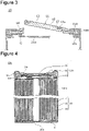
- a portion of the resin component 18 is fractured, as illustrated in FIG. 3 .
- a gas exhaust mechanism is thus configured such that a gas in the battery is exhausted. While the strength of the resin component 18 can be adjusted by its material quality and thickness, the resin component 18 may alternatively be provided with an easy fracture part like an annular groove.
- a portion to which the external lead is connected can be separated along the easy fracture part 16 from the metal component 12 because the resin component 18 is likely to be deformed to the outside of the battery even when only a portion of the easy fracture part 16 is fractured.
- the resin component 18 is fractured so that a gas in the battery is exhausted.
- the respective fracture strengths of the easy fracture part 16 and the resin component 18 and the fixing strength to the resin component 18 by the metal component 12 may be limited such that a relationship of P1 ⁇ P3 ⁇ P2 holds.
- the portion to which the external lead is connected can also be separated along the easy fracture part 16 from the metal component 12, like in the foregoing.
- the easy fracture part 16 is preferably formed in an annular shape.
- An annular easy fracture part may be formed by a stepped portion the thickness of which is changed in a radial direction of the inner end plate portion 15.
- the easy fracture part 16 may be partially discontinuous, like in a C shape, in a range in which the current interruption mechanism can be implemented.
- the fracture strength of the resin component 18 can be adjusted depending on its material quality and thickness, and an easy fracture part may also be formed in the resin component 18.
- An easy fracture part in the resin component 18 can be formed as an annular or C-shaped groove, for example.
- the easy fracture part may be formed by a stepped portion the thickness of which is changed in a radial direction of the resin component 18.
- the fixing strength to the resin component 18 by the metal component 12 can be adjusted by a press working pressure applied when compressing the resin component 18.
- the electrode assembly 20 is arranged in the exterior can 100.
- the positive electrode plate 21 constituting the electrode assembly 20 includes a positive electrode current collector and a positive electrode active material layer formed on the positive electrode current collector.
- the positive electrode active material layer is formed on both surfaces of the positive electrode current collector.
- a metal foil made of aluminum or the like, or a film having a surface layer of the metal, for example, is used for the positive electrode current collector.
- a preferable positive electrode current collector is a metal foil mainly composed of aluminum or an aluminum alloy. The thickness of the positive electrode current collector is 10 ⁇ m to 30 ⁇ m, for example.
- the positive electrode active material layer preferably contains a positive electrode active material, a conductive agent, and a binder.
- the positive electrode plate 21 is produced by applying a positive electrode mixture slurry containing a positive electrode active material, a conductive agent, a binder, and a dispersion medium such as N-methyl-2-pyrrolidon (NMP) onto both surfaces of the positive electrode current collector, followed by drying and rolling.
- NMP N-methyl-2-pyrrolidon
- the positive electrode active material can include a lithium-containing transition metal composite oxide containing a transition metal element such as Co, Mn, or Ni.
- the lithium-containing transition metal composite oxide is not particularly limited, but may be preferably a composite oxide represented by a general formula: Li 1+x MO 2 (in the formula, - 0.2 ⁇ x ⁇ 0.2, where M contains at least one of Ni, Co, Mn, and Al).
- Examples of the above-described conductive agent include carbon materials such as carbon black (CB), acetylene black (AB), ketjen black, and graphite.
- Examples of the above-described binder include fluorine-based resin such as polytetrafluoroethylene (PTFE) or polyvinylidene fluoride (PVdF), polyacrylonitrile (PAN), polyimide (PI), acrylic-based resin, and polyolefin-based resin.
- PTFE polytetrafluoroethylene
- PVdF polyvinylidene fluoride
- PAN polyacrylonitrile
- PI polyimide
- acrylic-based resin and polyolefin-based resin.
- the resins and carboxymethyl cellulose (CMC) or its salt, polyethylene oxide (PEO), or the like may be used in combination. These may be each used alone or in a combination of two or more thereof.
- the positive electrode plate 21 is provided with a positive electrode current collector exposed part (not illustrated) where a surface of a metal composing a positive electrode current collector is exposed.
- the positive electrode current collector exposed part is a portion to which the positive electrode lead 21a is connected and is a portion where a surface of the positive electrode current collector is not covered with a positive electrode active material layer.
- One end-side portion of the positive electrode lead 21a is bonded to the positive electrode current collector exposed part by ultrasonic welding, for example.
- the other end-side portion of the positive electrode lead 21a is led out upward through an opening (not illustrated) formed in a disk-shaped first insulating plate 30 disposed on the upper side of the electrode assembly 20 and is connected to a lower surface (inner surface) of the flange portion 15a of the metal component 12.
- a material for the positive electrode lead 21a include aluminum, an aluminum alloy, nickel, a nickel alloy, iron, and stainless steel.
- the negative electrode plate 22 includes a negative electrode current collector and a negative electrode active material layer formed on the negative electrode current collector.
- a negative electrode active material layer is formed on both surfaces of the negative electrode current collector.
- the negative electrode plate 22 has a negative electrode current collector exposed part (not illustrated) provided in its winding-end end portion.
- the negative electrode current collector exposed part is a portion to which a negative electrode lead 22a is connected and is a portion where a surface of the negative electrode current collector is not covered with the negative electrode active material layer.
- One end-side portion of the negative electrode lead 22a is bonded to the negative electrode current collector exposed part by ultrasonic welding, for example.
- the other end-side portion of the negative electrode lead 22a is connected to a bottom portion of the exterior can 100 through the outer peripheral side of a disk-shaped second insulating plate 31 disposed on the lower side of the electrode assembly 20.
- the negative electrode active material layer preferably contains a negative electrode active material and a binder.
- the negative electrode plate 22 is produced by applying a negative electrode mixture slurry containing a negative electrode active material, a binder, and water, for example, on both surfaces of the negative electrode current collector, followed by drying and rolling.
- the negative electrode active material is not particularly limited as long as it can reversibly occlude and release lithium ions, and examples of the negative electrode active material to be used can include a carbon material such as natural graphite or artificial graphite, a metal to be alloyed with lithium, such as Si or Sn, an alloy containing these, and a composite oxide.
- a carbon material such as natural graphite or artificial graphite
- a metal to be alloyed with lithium such as Si or Sn
- an alloy containing these such as Si or Sn
- a composite oxide As the binder contained in the negative electrode active material layer, resin similar to that in the positive electrode plate 21, for example, is used. If the negative electrode mixture slurry is prepared with an aqueous solvent, styrene-butadiene rubber (SBR), CMC or its salt, a polyacrylic acid or its salt, polyvinyl alcohol, and the like can be used. These may be each used alone or in a combination of two or more thereof.
- SBR
- the negative electrode plate 22 is used by being wound with it being laminated on the positive electrode plate 21 via the separator 23.
- the negative electrode plate 22 may be electrically connected to the exterior can 100 by arranging a negative electrode current collector exposed part over the entire circumference of an outermost peripheral surface of the winding-end-side end portion of the negative electrode plate 22 and bringing the negative electrode current collector exposed part into contact with an inner peripheral surface of a cylindrical portion of the exterior can 100. This makes it possible to ensure more preferable current collectability.
- the one end-side portion of the negative electrode lead 22a may be bonded to the negative electrode current collector exposed part formed in a winding-start-side end portion of the negative electrode plate 22.
- a porous sheet having ion permeability and electrical insulation is used for the separator 23.
- the porous sheet can include a microporous thin film, a woven fabric, and a non-woven fabric.
- polyolefin-based resin such as polyethylene or polypropylene is preferable.
- the thickness of the separator 23 is 10 ⁇ m to 50 ⁇ m, for example.
- the separator 23 tends to be thinner as the battery increases in capacity and output power.
- the separator 23 has a melting point of approximately 130°C to 180°C, for example.
- the cylindrical battery 10 is assembled in the following manner, for example.
- the electrode assembly 20, together with the disk-shaped second insulating plate 31 on the lower side thereof is inserted into the inside of the exterior can 100 having a bottomed cylindrical shape produced by drawing a steel plate, and the negative electrode lead 22a connected to the negative electrode plate 22 is connected to the bottom portion of the exterior can 100 by welding.
- the disk-shaped first insulating plate 30 is inserted into the upper side of the electrode assembly 20 inside the exterior can 100, and a groove portion 101 ( FIG. 1 ) having a U shape in cross section is formed by plastic working over its entire circumference in its circumferential direction on the side of the opening above the first insulating plate 30 in the exterior can 100.
- the resin component 18 has been previously caulked and fixed to the outer peripheral side of the metal component 12.
- the resin component 18 is caulked and fixed to the metal component 12 after performing press working such that the resin component 18 is compressed by the inner end plate portion 15 and the outer end plate portion 13 of the metal component 12.
- the metal component 12 is then housed with the resin component 18 interposed therebetween on the groove portion 101 inside the exterior can 100 while the positive electrode lead 21a is folded, and a portion of the opening end of the exterior can 100 is caulked, thereby producing the sealed cylindrical battery 10.
- the outer end plate portion 13 is exposed as an uppermost layer portion of the cylindrical battery 10 at an upper end of the sealing member 11.
- an outer peripheral portion of the metal component 12 may be caulked and fixed in the one end portion of the exterior can 100 with the resin component 18 interposed therebetween. Then, press working may be performed such that the resin component 18 is compressed by the inner end plate portion 15 and the outer end plate portion 13.
- the above-described cylindrical battery 10 makes it possible to make the metal component 12 constituting the sealing member 11 have a current interruption function, thereby making it possible to reduce the number of components constituting the sealing member 11. As a result, the number of processing man-hours of the component requiring a processing accuracy can be reduced, resulting in reduction in manufacturing cost.
- FIG. 4 is a sectional view of a cylindrical battery 10a in a comparative example.
- a sealing structure at one end of an exterior can 100a includes a gasket 34 as a resin component and a sealing member 11a, unlike in the cylindrical battery 10 illustrated in FIG. 1 to FIG. 3 .
- the sealing member 11a includes three components, i.e., a valve member 36 made of a metal, an insulating member 38, and a metal body 40 having a ventilation hole. Respective central portions of the valve member 36 and the metal body 40 are connected to each other, and the insulating member 38 is interposed between their respective outer peripheral portions.
- An end portion, which has been led out from an electrode assembly 20, of a positive electrode lead 21a is connected to the metal body 40 radially outside a connection part between the valve member 36 and the metal body 40.
- the metal body 40 is provided with a thin portion along the connection part with the valve member 36.
- the number of components for providing the sealing member 11a with a current interruption function is as large as three, which places a large burden, such as an increase in the number of man-hours in processing. Such inconvenience can be prevented according to the embodiment illustrated in FIG. 1 to FIG. 3 .
Landscapes
- Chemical & Material Sciences (AREA)
- Chemical Kinetics & Catalysis (AREA)
- Electrochemistry (AREA)
- General Chemical & Material Sciences (AREA)
- Gas Exhaust Devices For Batteries (AREA)
- Sealing Battery Cases Or Jackets (AREA)
- Connection Of Batteries Or Terminals (AREA)
Abstract
Description
- The present disclosure relates to a cylindrical battery.
- In recent years, there has been a need for a secondary battery to have a further increased capacity because applications have been expanding to a power source for electric vehicles, a power storage device for utilizing natural energy, and the like. In electric vehicle and power storage devices, a battery module is used, which is formed by connecting a number of secondary batteries in series or in parallel via an external lead. As the capacity of the secondary battery increases, higher safety is required for the secondary battery and the battery module. Traditionally, when a battery internal pressure is abnormally increased due to overcharge of the secondary battery, for example, a current path in the secondary battery is caused to be interrupted to prevent thermal runaway and rupture of the secondary battery in advance.
- Patent Literature 1 describes a cylindrical battery in which a current interruption mechanism is incorporated into a sealing member that seals one end of an exterior can to ensure safety. The current interruption mechanism is configured by combining a valve member made of a metal, an insulating member, and a metal body having a ventilation hole. Respective central portions of the valve member and the metal body are connected to each other, and the insulating member is interposed between their respective outer peripheral portions. When a battery internal pressure increases, the metal body pulls a connection part with the valve member outward of the battery, and the connection part or a thin portion provided in the metal body is fractured so that a current path between the valve member and the metal body is interrupted. Further, when the battery internal pressure increases, the valve member is fractured with the thin portion of the valve member used as a starting point, whereby a gas in the battery is exhausted.
- PATENT LITERATURE 1: International Publication No.
WO 2016/157748 - In a configuration described in Patent Literature 1, the sealing member that closes the one end of the exterior can includes three components, i.e., the valve member, the insulating member, and the metal body to make the sealing member have a current interruption function. Since the components are required to reliably operate at the time of an abnormality in the battery, it is essential that each have a complicated and highly accurate processed shape. As the number of components constituting the sealing member increases, like in the configuration described in Patent Literature 1, this places a large burden such as an increase in the number of man-hours in processing. Thus, it is desired to reduce the number of components constituting the sealing member.
- It is an advantage of the present disclosure to provide a cylindrical battery capable of reducing the number of components constituting a sealing member that closes one end of an exterior can by making a metal component constituting the sealing member have a current interruption function.
- A cylindrical battery according to the present disclosure comprises an exterior can having a bottomed cylindrical shape, a sealing member that closes one end of the exterior can, an electrode assembly arranged in the exterior can, and a resin component having electrical insulation disposed between the exterior can and the sealing member, wherein the sealing member includes a metal component electrically connected to an electrode lead led out from the electrode assembly, the metal component includes an easy fracture part radially inside a connection part between the metal component and the electrode lead, and is caulked and fixed by the exterior can with the resin component interposed therebetween, and the resin component is caulked and fixed by the metal component more radially inside the metal component than the easy fracture part.
- The cylindrical battery according to present disclosure makes it possible to reduce the number of components constituting the sealing member because it is capable of making the metal component constituting the sealing member have a current interruption function.
-
-
FIG. 1 is a sectional view of a cylindrical battery according to an example of an embodiment. -
FIG. 2 is a diagram corresponding to a portion A inFIG. 1 and illustrating a state where a current interruption mechanism has operated due to an increase in battery internal pressure from a state illustrated inFIG. 1 . -
FIG. 3 is a diagram corresponding to the portion A inFIG. 1 and illustrating a state where a gas exhaust mechanism has operated due to a further increase in battery internal pressure from the state illustrated inFIG. 2 . -
FIG. 4 is a sectional view of a cylindrical battery in a comparative example. - An embodiment of the present invention will be described in detail below with reference to the accompanying drawings. In the following description, specific shapes, materials, and directions, for example, are examples to facilitate understanding of the present disclosure, and can be appropriately changed to match uses, purposes, and specifications, for example, of a cylindrical battery. Although a case where the cylindrical battery is a non-aqueous electrolyte secondary battery will be described below, the cylindrical battery is not limited to this.
-
FIG. 1 is a sectional view of acylindrical battery 10 according to the embodiment. For example, a non-aqueous electrolyte secondary battery such as a lithium ion battery is used for thecylindrical battery 10. Thecylindrical battery 10 is configured by housing anelectrode assembly 20 and a non-aqueous electrolyte (not illustrated) in a substantially cylindrical exterior can 100 having a bottomed cylindrical shape. A sealingmember 11 is fixed to an opening at one end (an upper end inFIG. 1 ) of the exterior can 100 with aresin component 18 having electrical insulation interposed therebetween. As a result, the opening at the one end of the exterior can 100 is closed by the sealingmember 11 with theresin component 18 interposed therebetween. Theresin component 18 is an insulating member, and has a function as a gasket that seals a space between the exterior can 100 and thesealing member 11, and also has a function of exhausting a gas when a battery internal pressure increases, as described below. The non-aqueous electrolyte contains a non-aqueous solvent and an electrolyte salt dissolved in the non-aqueous solvent. The non-aqueous electrolyte is not limited to a liquid electrolyte, and may be a solid electrolyte using a gel polymer or the like. - The
electrode assembly 20 is of a wound type, includes apositive electrode plate 21, anegative electrode plate 22, and aseparator 23, and is obtained by winding thepositive electrode plate 21 and thenegative electrode plate 22 in a spiral shape with theseparator 23 interposed therebetween. Hereinafter, one side in a winding axis direction of theelectrode assembly 20 and the other side in the winding axis direction may be respectively referred to as "upper" and "lower". - The sealing
member 11 is composed of only ametal component 12. Themetal component 12 has a function as a positive electrode terminal and a function as a current interruption function for interrupting a current path when the battery internal pressure increases. Themetal component 12 includes a disk-shaped outerend plate portion 13 disposed at an outer end of the battery, a disk-shaped innerend plate portion 15 disposed at an inner end of the battery, and a disk-shaped connection part 17 that connects the outerend plate portion 13 and the innerend plate portion 15 to each other. The outer diameter of the outerend plate portion 13 is smaller than the outer diameter of the innerend plate portion 15. The outer diameter of theconnection part 17 is smaller than the respective outer diameters of the outerend plate portion 13 and the innerend plate portion 15. The outerend plate portion 13, the innerend plate portion 15, and theconnection part 17 are coaxial such that their respective center axes match one another. As a result, acircular groove portion 12a is formed between the outerend plate portion 13 and the innerend plate portion 15 of themetal component 12, and aflange portion 15a is formed radially outside theconnection part 17 as part of the innerend plate portion 15. Themetal component 12 can be produced by aluminum or an aluminum alloy, for example. An external lead (not illustrated) to be electrically connected to another cylindrical battery in a battery module (not illustrated) is bonded by welding to an outer surface (an upper surface inFIG. 1 ) of an external terminal composed of the outerend plate portion 13. - An end portion of a
positive electrode lead 21a led out from theelectrode assembly 20 is connected to an inner side surface of a portion in a radial direction of theflange portion 15a. Thepositive electrode lead 21a corresponds to an electrode lead. Further, theflange portion 15a includes aneasy fracture part 16 radially inside a connection part G between themetal component 12 and thepositive electrode lead 21a. Theeasy fracture part 16 is an annular thin portion formed in a portion in the radial direction of theflange portion 15a, and theeasy fracture part 16 is formed once a circularlyannular groove 15b is formed in a portion in the radial direction of an inner side surface (a lower side surface inFIG. 1 ) of theflange portion 15a. Theeasy fracture part 16 can also be formed on an outer side surface (an upper side surface inFIG. 1 ) of theflange portion 15a. - The
resin component 18 is disposed between an inner peripheral surface of the opening formed at the one end (the upper end inFIG. 1 ) of the exterior can 100 and an outer peripheral surface of thesealing member 11. A portion in a circumferential direction of theresin component 18 has a substantially J shape in cross section, whose battery outer side end portion (an upper end portion inFIG. 1 ) is longer than its battery inner side end portion (a lower end portion inFIG. 1 ), and its entirety is formed into an annular shape in a planar view. Theflange portion 15a of the innerend plate portion 15 is caulked and fixed by the exterior can 100 with theresin component 18 interposed therebetween. Theresin component 18 is held in a compressed state between the one end of the exterior can 100 and the outer peripheral surface of the sealingmember 11, and is caulked and fixed by themetal component 12 more radially inside themetal component 12 than theeasy fracture part 16. For example, as illustrated inFigure 1 , a distal end portion of theresin component 18 extending from between theflange portion 15a and the one end of the exterior can 100 is caulked and fixed by the outerend plate portion 13 and the innerend plate portion 15. With the distal end portion of theresin component 18 being caulked and fixed by themetal component 12 over its entire circumference, a sealing structure is formed between the distal end portion of theresin component 18 and thesealing member 11. As a result, even if theeasy fracture part 16 is fractured due to the increase in the battery internal pressure, a sealing property in the battery is ensured. A material that ensures electrical insulation and does not affect a battery characteristic can be used for theresin component 18. Polymer resin is preferable as a material for theresin component 18, and examples thereof include polypropylene (PP) resin and polybutylene terephthalate (PBT) resin. - As described above, in the
cylindrical battery 10, the sealing property in the battery is also ensured after theeasy fracture part 16 is fractured due to the increase in the battery internal pressure. When the battery internal pressure further increases, theresin component 18 is deformed to the outside of the battery so that a portion including the outerend plate portion 13 is separated along theeasy fracture part 16 from themetal component 12, as illustrated inFIG. 2 . A current interruption mechanism is thus configured such that a current path between a central portion of themetal component 12 to which the external lead is connected and thepositive electrode lead 21a is interrupted. When the battery internal pressure further increases, a portion of theresin component 18 is fractured, as illustrated inFIG. 3 . A gas exhaust mechanism is thus configured such that a gas in the battery is exhausted. While the strength of theresin component 18 can be adjusted by its material quality and thickness, theresin component 18 may alternatively be provided with an easy fracture part like an annular groove. - The above-described current interruption mechanism and gas exhaust mechanism will be described in more detail. When a battery internal pressure at which the
easy fracture part 16 is fractured is defined as PI, a battery internal pressure at which theresin component 18 is fractured as P2, and a battery internal pressure at which theresin component 18 comes off themetal component 12 as P3, the respective fracture strengths of theeasy fracture part 16 and theresin component 18 and the fixing strength to theresin component 18 by themetal component 12 are limited such that a relationship of P1 < P2 < P3 holds. When the battery internal pressure reaches PI, a portion to which the external lead is connected can be separated along theeasy fracture part 16 from themetal component 12 because theresin component 18 is likely to be deformed to the outside of the battery even when only a portion of theeasy fracture part 16 is fractured. When the battery internal pressure increases and reaches P2 after theeasy fracture part 16 is fractured, theresin component 18 is fractured so that a gas in the battery is exhausted. The respective fracture strengths of theeasy fracture part 16 and theresin component 18 and the fixing strength to theresin component 18 by themetal component 12 may be limited such that a relationship of P1 < P3 < P2 holds. In this case, the portion to which the external lead is connected can also be separated along theeasy fracture part 16 from themetal component 12, like in the foregoing. When the battery internal pressure increases and reaches P3 after theeasy fracture part 16 is fractured, the distal end portion of theresin component 18 comes off themetal component 12 so that a gas in the battery is exhausted. In the foregoing relational expression, P2 and P3 may satisfy a relationship of P2 = P3. - The
easy fracture part 16 is preferably formed in an annular shape. An annular easy fracture part may be formed by a stepped portion the thickness of which is changed in a radial direction of the innerend plate portion 15. Theeasy fracture part 16 may be partially discontinuous, like in a C shape, in a range in which the current interruption mechanism can be implemented. The fracture strength of theresin component 18 can be adjusted depending on its material quality and thickness, and an easy fracture part may also be formed in theresin component 18. An easy fracture part in theresin component 18 can be formed as an annular or C-shaped groove, for example. The easy fracture part may be formed by a stepped portion the thickness of which is changed in a radial direction of theresin component 18. The fixing strength to theresin component 18 by themetal component 12 can be adjusted by a press working pressure applied when compressing theresin component 18. - Then, the
electrode assembly 20 will be described. Theelectrode assembly 20 is arranged in the exterior can 100. Thepositive electrode plate 21 constituting theelectrode assembly 20 includes a positive electrode current collector and a positive electrode active material layer formed on the positive electrode current collector. For example, the positive electrode active material layer is formed on both surfaces of the positive electrode current collector. A metal foil made of aluminum or the like, or a film having a surface layer of the metal, for example, is used for the positive electrode current collector. A preferable positive electrode current collector is a metal foil mainly composed of aluminum or an aluminum alloy. The thickness of the positive electrode current collector is 10 µm to 30 µm, for example. - The positive electrode active material layer preferably contains a positive electrode active material, a conductive agent, and a binder. The
positive electrode plate 21 is produced by applying a positive electrode mixture slurry containing a positive electrode active material, a conductive agent, a binder, and a dispersion medium such as N-methyl-2-pyrrolidon (NMP) onto both surfaces of the positive electrode current collector, followed by drying and rolling. - Examples of the positive electrode active material can include a lithium-containing transition metal composite oxide containing a transition metal element such as Co, Mn, or Ni. The lithium-containing transition metal composite oxide is not particularly limited, but may be preferably a composite oxide represented by a general formula: Li1+xMO2 (in the formula, - 0.2 < x ≤ 0.2, where M contains at least one of Ni, Co, Mn, and Al).
- Examples of the above-described conductive agent include carbon materials such as carbon black (CB), acetylene black (AB), ketjen black, and graphite. Examples of the above-described binder include fluorine-based resin such as polytetrafluoroethylene (PTFE) or polyvinylidene fluoride (PVdF), polyacrylonitrile (PAN), polyimide (PI), acrylic-based resin, and polyolefin-based resin. The resins and carboxymethyl cellulose (CMC) or its salt, polyethylene oxide (PEO), or the like may be used in combination. These may be each used alone or in a combination of two or more thereof.
- The
positive electrode plate 21 is provided with a positive electrode current collector exposed part (not illustrated) where a surface of a metal composing a positive electrode current collector is exposed. The positive electrode current collector exposed part is a portion to which thepositive electrode lead 21a is connected and is a portion where a surface of the positive electrode current collector is not covered with a positive electrode active material layer. One end-side portion of thepositive electrode lead 21a is bonded to the positive electrode current collector exposed part by ultrasonic welding, for example. The other end-side portion of thepositive electrode lead 21a is led out upward through an opening (not illustrated) formed in a disk-shaped first insulatingplate 30 disposed on the upper side of theelectrode assembly 20 and is connected to a lower surface (inner surface) of theflange portion 15a of themetal component 12. Examples of a material for thepositive electrode lead 21a include aluminum, an aluminum alloy, nickel, a nickel alloy, iron, and stainless steel. - The
negative electrode plate 22 includes a negative electrode current collector and a negative electrode active material layer formed on the negative electrode current collector. For example, a negative electrode active material layer is formed on both surfaces of the negative electrode current collector. Further, thenegative electrode plate 22 has a negative electrode current collector exposed part (not illustrated) provided in its winding-end end portion. The negative electrode current collector exposed part is a portion to which anegative electrode lead 22a is connected and is a portion where a surface of the negative electrode current collector is not covered with the negative electrode active material layer. One end-side portion of thenegative electrode lead 22a is bonded to the negative electrode current collector exposed part by ultrasonic welding, for example. The other end-side portion of thenegative electrode lead 22a is connected to a bottom portion of the exterior can 100 through the outer peripheral side of a disk-shaped second insulatingplate 31 disposed on the lower side of theelectrode assembly 20. - The negative electrode active material layer preferably contains a negative electrode active material and a binder. The
negative electrode plate 22 is produced by applying a negative electrode mixture slurry containing a negative electrode active material, a binder, and water, for example, on both surfaces of the negative electrode current collector, followed by drying and rolling. - The negative electrode active material is not particularly limited as long as it can reversibly occlude and release lithium ions, and examples of the negative electrode active material to be used can include a carbon material such as natural graphite or artificial graphite, a metal to be alloyed with lithium, such as Si or Sn, an alloy containing these, and a composite oxide. As the binder contained in the negative electrode active material layer, resin similar to that in the
positive electrode plate 21, for example, is used. If the negative electrode mixture slurry is prepared with an aqueous solvent, styrene-butadiene rubber (SBR), CMC or its salt, a polyacrylic acid or its salt, polyvinyl alcohol, and the like can be used. These may be each used alone or in a combination of two or more thereof. - The
negative electrode plate 22 is used by being wound with it being laminated on thepositive electrode plate 21 via theseparator 23. With the use of thenegative electrode lead 22a or thenegative electrode lead 22a being omitted, thenegative electrode plate 22 may be electrically connected to the exterior can 100 by arranging a negative electrode current collector exposed part over the entire circumference of an outermost peripheral surface of the winding-end-side end portion of thenegative electrode plate 22 and bringing the negative electrode current collector exposed part into contact with an inner peripheral surface of a cylindrical portion of the exterior can 100. This makes it possible to ensure more preferable current collectability. At this time, the one end-side portion of thenegative electrode lead 22a may be bonded to the negative electrode current collector exposed part formed in a winding-start-side end portion of thenegative electrode plate 22. - A porous sheet having ion permeability and electrical insulation is used for the
separator 23. Specific examples of the porous sheet can include a microporous thin film, a woven fabric, and a non-woven fabric. As a material for theseparator 23, polyolefin-based resin such as polyethylene or polypropylene is preferable. The thickness of theseparator 23 is 10 µm to 50 µm, for example. Theseparator 23 tends to be thinner as the battery increases in capacity and output power. Theseparator 23 has a melting point of approximately 130°C to 180°C, for example. - The
cylindrical battery 10 is assembled in the following manner, for example. For example, theelectrode assembly 20, together with the disk-shaped second insulatingplate 31 on the lower side thereof, is inserted into the inside of the exterior can 100 having a bottomed cylindrical shape produced by drawing a steel plate, and thenegative electrode lead 22a connected to thenegative electrode plate 22 is connected to the bottom portion of the exterior can 100 by welding. Then, the disk-shaped first insulatingplate 30 is inserted into the upper side of theelectrode assembly 20 inside the exterior can 100, and a groove portion 101 (FIG. 1 ) having a U shape in cross section is formed by plastic working over its entire circumference in its circumferential direction on the side of the opening above the first insulatingplate 30 in the exterior can 100. Then, a predetermined amount of prepared non-aqueous electrolyte is injected into the exterior can 100 including theelectrode assembly 20. Thepositive electrode lead 21a connected to thepositive electrode plate 21 is then connected by welding to theflange portion 15a of themetal component 12 constituting the sealingmember 11. At this time, theresin component 18 has been previously caulked and fixed to the outer peripheral side of themetal component 12. For example, theresin component 18 is caulked and fixed to themetal component 12 after performing press working such that theresin component 18 is compressed by the innerend plate portion 15 and the outerend plate portion 13 of themetal component 12. Themetal component 12 is then housed with theresin component 18 interposed therebetween on thegroove portion 101 inside the exterior can 100 while thepositive electrode lead 21a is folded, and a portion of the opening end of the exterior can 100 is caulked, thereby producing the sealedcylindrical battery 10. At this time, the outerend plate portion 13 is exposed as an uppermost layer portion of thecylindrical battery 10 at an upper end of the sealingmember 11. - Alternatively, after the
resin component 18 and themetal component 12 are arranged, without being caulked and fixed, inside one end portion of the exterior can 100, an outer peripheral portion of themetal component 12 may be caulked and fixed in the one end portion of the exterior can 100 with theresin component 18 interposed therebetween. Then, press working may be performed such that theresin component 18 is compressed by the innerend plate portion 15 and the outerend plate portion 13. - The above-described
cylindrical battery 10 makes it possible to make themetal component 12 constituting the sealingmember 11 have a current interruption function, thereby making it possible to reduce the number of components constituting the sealingmember 11. As a result, the number of processing man-hours of the component requiring a processing accuracy can be reduced, resulting in reduction in manufacturing cost. -
FIG. 4 is a sectional view of acylindrical battery 10a in a comparative example. In thecylindrical battery 10a in the comparative example, a sealing structure at one end of an exterior can 100a includes agasket 34 as a resin component and a sealingmember 11a, unlike in thecylindrical battery 10 illustrated inFIG. 1 to FIG. 3 . The sealingmember 11a includes three components, i.e., avalve member 36 made of a metal, an insulatingmember 38, and ametal body 40 having a ventilation hole. Respective central portions of thevalve member 36 and themetal body 40 are connected to each other, and the insulatingmember 38 is interposed between their respective outer peripheral portions. An end portion, which has been led out from anelectrode assembly 20, of apositive electrode lead 21a is connected to themetal body 40 radially outside a connection part between thevalve member 36 and themetal body 40. Themetal body 40 is provided with a thin portion along the connection part with thevalve member 36. When a battery internal pressure increases, thevalve member 36 is deformed upward upon receipt of the internal pressure, to pull the connection part with themetal body 40 outward of the battery. The connection part or the thin portion provided in themetal body 40 is fractured so that a current path between thevalve member 36 and thepositive electrode lead 21a is interrupted. Further, when the battery internal pressure increases, thevalve member 36 is fractured starting at athin portion 36a in thevalve member 36 so that a gas in the battery is exhausted. In thecylindrical battery 10a in the comparative example, the number of components for providing the sealingmember 11a with a current interruption function is as large as three, which places a large burden, such as an increase in the number of man-hours in processing. Such inconvenience can be prevented according to the embodiment illustrated inFIG. 1 to FIG. 3 . - 10, 10a cylindrical battery, 11, 11a sealing member, 12 metal component, 12a groove portion, 13 outer end plate portion, 15 inner end plate portion, 15a flange portion, 15b groove, 17 connection part, 18 resin component, 20 electrode assembly, 21 positive electrode plate, 21a positive electrode lead, 22 negative electrode plate, 22a negative electrode lead, 23 separator, 30 first insulating plate, 31 second insulating plate, 34 gasket, 36 valve member, 36a thin portion, 38 insulating member, 40 metal body.
Claims (5)
- A cylindrical battery comprising:an exterior can having a bottomed cylindrical shape;a sealing member that closes one end of the exterior can;an electrode assembly arranged in the exterior can; anda resin component having electrical insulation disposed between the exterior can and the sealing member, whereinthe sealing member includes a metal component electrically connected to an electrode lead led out from the electrode assembly,the metal component includes an easy fracture part radially inside a connection part between the metal component and the electrode lead, and is caulked and fixed by the exterior can with the resin component interposed therebetween, andthe resin component is caulked and fixed by the metal component more radially inside the metal component than the easy fracture part.
- The cylindrical battery according to claim 1, whereinthe metal component includes an inner end plate portion, an outer end plate portion, and a connection part connecting the inner end plate portion and the outer end plate portion,a flange portion radially outside the inner end plate portion is caulked and fixed to one end of the exterior can with the resin component interposed therebetween, anda distal end portion of the resin component extending from between the flange portion and the one end of the exterior can is caulked and fixed to the inner end plate portion and the outer end plate portion.
- The cylindrical battery according to claim 1 or 2, wherein
the easy fracture part is formed as an annular groove. - The cylindrical battery according to any one of claims 1 to 3, wherein
when a battery internal pressure increases, the easy fracture part is fractured over its entirety in its circumferential direction so that a current path between a central portion of the metal component and the electrode lead is interrupted, and when the battery internal pressure further increases, an outer-side portion of the easy fracture part of the resin component is fractured so that a gas in the battery is exhausted. - The cylindrical battery according to any one of claims 1 to 3, wherein
when a battery internal pressure increases, the easy fracture part is fractured over its entirety in its circumferential direction so that a current path between a central portion of the metal component and the electrode lead is interrupted, and when the battery internal pressure further increases, a distal end portion of the resin component comes off the metal component so that a gas in the battery is exhausted.
Applications Claiming Priority (2)
| Application Number | Priority Date | Filing Date | Title |
|---|---|---|---|
| JP2019227988 | 2019-12-18 | ||
| PCT/JP2020/045746 WO2021124995A1 (en) | 2019-12-18 | 2020-12-09 | Cylindrical battery |
Publications (2)
| Publication Number | Publication Date |
|---|---|
| EP4080670A1 true EP4080670A1 (en) | 2022-10-26 |
| EP4080670A4 EP4080670A4 (en) | 2023-08-02 |
Family
ID=76477459
Family Applications (1)
| Application Number | Title | Priority Date | Filing Date |
|---|---|---|---|
| EP20901542.9A Pending EP4080670A4 (en) | 2019-12-18 | 2020-12-09 | CYLINDRICAL BATTERY |
Country Status (5)
| Country | Link |
|---|---|
| US (1) | US12347878B2 (en) |
| EP (1) | EP4080670A4 (en) |
| JP (1) | JP7686570B2 (en) |
| CN (1) | CN114868305B (en) |
| WO (1) | WO2021124995A1 (en) |
Cited By (2)
| Publication number | Priority date | Publication date | Assignee | Title |
|---|---|---|---|---|
| EP4123799A4 (en) * | 2020-03-16 | 2023-11-15 | SANYO Electric Co., Ltd. | CYLINDRICAL BATTERY |
| WO2023242167A1 (en) * | 2022-06-14 | 2023-12-21 | Northvolt Ab | A cylindrical secondary cell |
Families Citing this family (7)
| Publication number | Priority date | Publication date | Assignee | Title |
|---|---|---|---|---|
| CN114868305B (en) * | 2019-12-18 | 2025-10-28 | 松下新能源株式会社 | Cylindrical batteries |
| US20240339736A1 (en) * | 2021-12-15 | 2024-10-10 | Lg Energy Solution, Ltd. | Secondary Battery and Battery Module Including the Same |
| JPWO2023127721A1 (en) * | 2021-12-28 | 2023-07-06 | ||
| US20250192293A1 (en) * | 2022-03-17 | 2025-06-12 | Panasonic Energy Co., Ltd. | Cylindrical battery |
| WO2024057631A1 (en) * | 2022-09-14 | 2024-03-21 | パナソニックエナジー株式会社 | Battery |
| CN115498354B (en) * | 2022-11-14 | 2023-03-03 | 宁德新能源科技有限公司 | Electrochemical device and power utilization device |
| KR20260118856A (en) * | 2025-01-24 | 2026-07-31 | 삼성에스디아이 주식회사 | Secondary battery and method for manufacturing secondary battery |
Family Cites Families (15)
| Publication number | Priority date | Publication date | Assignee | Title |
|---|---|---|---|---|
| JPH10188934A (en) * | 1996-12-24 | 1998-07-21 | Sony Corp | Cylindrical battery |
| US20040043286A1 (en) * | 2002-08-28 | 2004-03-04 | Janmey Robert M. | Seal for an electrochemical cell |
| US20150072179A1 (en) | 2012-01-27 | 2015-03-12 | Toshiyuki Itabashi | Sealed battery |
| CN104956516B (en) * | 2013-01-31 | 2017-09-26 | 三洋电机株式会社 | Enclosed-type battery |
| JP6538650B2 (en) * | 2014-03-28 | 2019-07-03 | 三洋電機株式会社 | Cylindrical sealed battery |
| US20180026238A1 (en) | 2015-03-06 | 2018-01-25 | Sanyo Electric Co., Ltd. | Sealed batteries |
| WO2016157748A1 (en) | 2015-03-27 | 2016-10-06 | 三洋電機株式会社 | Circular cylindrical battery and method for manufacturing same |
| JP6801645B2 (en) | 2015-03-27 | 2020-12-16 | 三洋電機株式会社 | Cylindrical battery |
| JP6859852B2 (en) | 2017-05-31 | 2021-04-14 | 三洋電機株式会社 | Square secondary batteries, assembled batteries and vehicles using them |
| WO2019026527A1 (en) * | 2017-07-31 | 2019-02-07 | パナソニックIpマネジメント株式会社 | Cylindrical battery |
| KR102275779B1 (en) * | 2017-11-17 | 2021-07-13 | 주식회사 엘지에너지솔루션 | Secondary battery |
| KR20190138509A (en) | 2018-06-05 | 2019-12-13 | 주식회사 엘지화학 | Secondary battery |
| US11699834B2 (en) * | 2019-01-18 | 2023-07-11 | Sanyo Electric Co., Ltd. | Sealed battery |
| EP4068443B1 (en) * | 2019-11-29 | 2026-06-10 | Panasonic Energy Co., Ltd. | Sealed battery |
| CN114868305B (en) * | 2019-12-18 | 2025-10-28 | 松下新能源株式会社 | Cylindrical batteries |
-
2020
- 2020-12-09 CN CN202080087126.0A patent/CN114868305B/en active Active
- 2020-12-09 WO PCT/JP2020/045746 patent/WO2021124995A1/en not_active Ceased
- 2020-12-09 JP JP2021565504A patent/JP7686570B2/en active Active
- 2020-12-09 US US17/785,267 patent/US12347878B2/en active Active
- 2020-12-09 EP EP20901542.9A patent/EP4080670A4/en active Pending
Cited By (2)
| Publication number | Priority date | Publication date | Assignee | Title |
|---|---|---|---|---|
| EP4123799A4 (en) * | 2020-03-16 | 2023-11-15 | SANYO Electric Co., Ltd. | CYLINDRICAL BATTERY |
| WO2023242167A1 (en) * | 2022-06-14 | 2023-12-21 | Northvolt Ab | A cylindrical secondary cell |
Also Published As
| Publication number | Publication date |
|---|---|
| WO2021124995A1 (en) | 2021-06-24 |
| EP4080670A4 (en) | 2023-08-02 |
| CN114868305B (en) | 2025-10-28 |
| JP7686570B2 (en) | 2025-06-02 |
| US12347878B2 (en) | 2025-07-01 |
| US20220376332A1 (en) | 2022-11-24 |
| CN114868305A (en) | 2022-08-05 |
| JPWO2021124995A1 (en) | 2021-06-24 |
Similar Documents
| Publication | Publication Date | Title |
|---|---|---|
| US12347878B2 (en) | Cylindrical battery | |
| EP4068443A1 (en) | Sealed battery | |
| US11450892B2 (en) | Nonaqueous electrolyte secondary battery | |
| US11450893B2 (en) | Nonaqueous electrolyte secondary battery | |
| US11495833B2 (en) | Cylindrical battery | |
| US11502382B2 (en) | Nonaqueous electrolyte secondary battery | |
| JP7709293B2 (en) | Cylindrical battery | |
| CN118541858A (en) | Cylindrical battery | |
| JP2008130482A (en) | Cylindrical secondary battery | |
| JP5171441B2 (en) | Sealed secondary battery | |
| WO2018105398A1 (en) | Cylindrical nonaqueous electrolyte secondary battery | |
| CN112400250A (en) | Non-aqueous electrolyte secondary battery | |
| EP4270613A1 (en) | Hermetically sealed battery | |
| CN118891780A (en) | Non-aqueous electrolyte secondary battery | |
| US20240313305A1 (en) | Cylindrical battery | |
| WO2023054005A1 (en) | Cylindrical battery | |
| US20260051581A1 (en) | Energy storage element and method for producing an energy storage element | |
| US20250192293A1 (en) | Cylindrical battery | |
| JP2020053262A (en) | Battery lead connector and battery module | |
| WO2012086514A1 (en) | Lithium-ion secondary battery | |
| WO2025095073A1 (en) | Power storage device | |
| WO2024161920A1 (en) | Cylindrical battery | |
| CN118872143A (en) | Cylindrical battery |
Legal Events
| Date | Code | Title | Description |
|---|---|---|---|
| STAA | Information on the status of an ep patent application or granted ep patent |
Free format text: STATUS: THE INTERNATIONAL PUBLICATION HAS BEEN MADE |
|
| PUAI | Public reference made under article 153(3) epc to a published international application that has entered the european phase |
Free format text: ORIGINAL CODE: 0009012 |
|
| STAA | Information on the status of an ep patent application or granted ep patent |
Free format text: STATUS: REQUEST FOR EXAMINATION WAS MADE |
|
| 17P | Request for examination filed |
Effective date: 20220616 |
|
| AK | Designated contracting states |
Kind code of ref document: A1 Designated state(s): AL AT BE BG CH CY CZ DE DK EE ES FI FR GB GR HR HU IE IS IT LI LT LU LV MC MK MT NL NO PL PT RO RS SE SI SK SM TR |
|
| DAV | Request for validation of the european patent (deleted) | ||
| DAX | Request for extension of the european patent (deleted) | ||
| A4 | Supplementary search report drawn up and despatched |
Effective date: 20230703 |
|
| RIC1 | Information provided on ipc code assigned before grant |
Ipc: H01M 50/578 20210101ALI20230627BHEP Ipc: H01M 50/184 20210101ALI20230627BHEP Ipc: H01M 50/107 20210101ALI20230627BHEP Ipc: H01M 50/531 20210101ALI20230627BHEP Ipc: H01M 50/342 20210101ALI20230627BHEP Ipc: H01M 50/183 20210101ALI20230627BHEP Ipc: H01M 50/147 20210101ALI20230627BHEP Ipc: H01M 50/572 20210101AFI20230627BHEP |
|
| STAA | Information on the status of an ep patent application or granted ep patent |
Free format text: STATUS: EXAMINATION IS IN PROGRESS |
|
| 17Q | First examination report despatched |
Effective date: 20260219 |