EP4080653A1 - Battery cell, battery, electric device, and method and device for preparing battery cell - Google Patents
Battery cell, battery, electric device, and method and device for preparing battery cell Download PDFInfo
- Publication number
- EP4080653A1 EP4080653A1 EP21827164.1A EP21827164A EP4080653A1 EP 4080653 A1 EP4080653 A1 EP 4080653A1 EP 21827164 A EP21827164 A EP 21827164A EP 4080653 A1 EP4080653 A1 EP 4080653A1
- Authority
- EP
- European Patent Office
- Prior art keywords
- end cover
- battery cell
- pressure relief
- relief mechanism
- insulating member
- Prior art date
- Legal status (The legal status is an assumption and is not a legal conclusion. Google has not performed a legal analysis and makes no representation as to the accuracy of the status listed.)
- Pending
Links
- 238000000034 method Methods 0.000 title abstract description 9
- 230000007246 mechanism Effects 0.000 claims abstract description 170
- 230000002093 peripheral effect Effects 0.000 claims description 25
- 238000009423 ventilation Methods 0.000 claims description 14
- 238000004519 manufacturing process Methods 0.000 claims description 10
- 239000008151 electrolyte solution Substances 0.000 description 21
- 238000010586 diagram Methods 0.000 description 20
- 230000000694 effects Effects 0.000 description 10
- 239000000243 solution Substances 0.000 description 9
- 239000007789 gas Substances 0.000 description 8
- 238000003466 welding Methods 0.000 description 7
- 230000009471 action Effects 0.000 description 6
- 230000000712 assembly Effects 0.000 description 6
- 238000000429 assembly Methods 0.000 description 6
- 239000007773 negative electrode material Substances 0.000 description 6
- 230000000149 penetrating effect Effects 0.000 description 6
- 239000007774 positive electrode material Substances 0.000 description 6
- 239000000463 material Substances 0.000 description 5
- 230000004044 response Effects 0.000 description 5
- 238000013461 design Methods 0.000 description 4
- 230000003116 impacting effect Effects 0.000 description 4
- 229910001416 lithium ion Inorganic materials 0.000 description 4
- 230000002829 reductive effect Effects 0.000 description 4
- HBBGRARXTFLTSG-UHFFFAOYSA-N Lithium ion Chemical compound [Li+] HBBGRARXTFLTSG-UHFFFAOYSA-N 0.000 description 3
- 230000002159 abnormal effect Effects 0.000 description 3
- 230000008859 change Effects 0.000 description 3
- 238000004891 communication Methods 0.000 description 3
- 238000011161 development Methods 0.000 description 3
- 238000007599 discharging Methods 0.000 description 3
- 238000005516 engineering process Methods 0.000 description 3
- 230000008569 process Effects 0.000 description 3
- 238000013459 approach Methods 0.000 description 2
- 230000008901 benefit Effects 0.000 description 2
- 229910052799 carbon Inorganic materials 0.000 description 2
- 230000006378 damage Effects 0.000 description 2
- 230000006870 function Effects 0.000 description 2
- 229910021645 metal ion Inorganic materials 0.000 description 2
- VNWKTOKETHGBQD-UHFFFAOYSA-N methane Chemical compound C VNWKTOKETHGBQD-UHFFFAOYSA-N 0.000 description 2
- 230000004048 modification Effects 0.000 description 2
- 238000012986 modification Methods 0.000 description 2
- 230000001681 protective effect Effects 0.000 description 2
- OKTJSMMVPCPJKN-UHFFFAOYSA-N Carbon Chemical compound [C] OKTJSMMVPCPJKN-UHFFFAOYSA-N 0.000 description 1
- RYGMFSIKBFXOCR-UHFFFAOYSA-N Copper Chemical compound [Cu] RYGMFSIKBFXOCR-UHFFFAOYSA-N 0.000 description 1
- 235000015842 Hesperis Nutrition 0.000 description 1
- 235000012633 Iberis amara Nutrition 0.000 description 1
- WHXSMMKQMYFTQS-UHFFFAOYSA-N Lithium Chemical compound [Li] WHXSMMKQMYFTQS-UHFFFAOYSA-N 0.000 description 1
- JLVVSXFLKOJNIY-UHFFFAOYSA-N Magnesium ion Chemical compound [Mg+2] JLVVSXFLKOJNIY-UHFFFAOYSA-N 0.000 description 1
- FKNQFGJONOIPTF-UHFFFAOYSA-N Sodium cation Chemical compound [Na+] FKNQFGJONOIPTF-UHFFFAOYSA-N 0.000 description 1
- IDSMHEZTLOUMLM-UHFFFAOYSA-N [Li].[O].[Co] Chemical class [Li].[O].[Co] IDSMHEZTLOUMLM-UHFFFAOYSA-N 0.000 description 1
- JDZCKJOXGCMJGS-UHFFFAOYSA-N [Li].[S] Chemical compound [Li].[S] JDZCKJOXGCMJGS-UHFFFAOYSA-N 0.000 description 1
- 230000004308 accommodation Effects 0.000 description 1
- 230000002411 adverse Effects 0.000 description 1
- 229910052782 aluminium Inorganic materials 0.000 description 1
- XAGFODPZIPBFFR-UHFFFAOYSA-N aluminium Chemical compound [Al] XAGFODPZIPBFFR-UHFFFAOYSA-N 0.000 description 1
- 230000000903 blocking effect Effects 0.000 description 1
- 229910052802 copper Inorganic materials 0.000 description 1
- 239000010949 copper Substances 0.000 description 1
- 238000005336 cracking Methods 0.000 description 1
- 238000005520 cutting process Methods 0.000 description 1
- QHGJSLXSVXVKHZ-UHFFFAOYSA-N dilithium;dioxido(dioxo)manganese Chemical compound [Li+].[Li+].[O-][Mn]([O-])(=O)=O QHGJSLXSVXVKHZ-UHFFFAOYSA-N 0.000 description 1
- 238000005553 drilling Methods 0.000 description 1
- 239000003792 electrolyte Substances 0.000 description 1
- 238000004134 energy conservation Methods 0.000 description 1
- 230000007613 environmental effect Effects 0.000 description 1
- 238000004880 explosion Methods 0.000 description 1
- 239000012634 fragment Substances 0.000 description 1
- 239000000446 fuel Substances 0.000 description 1
- 239000002737 fuel gas Substances 0.000 description 1
- 230000006872 improvement Effects 0.000 description 1
- 238000001746 injection moulding Methods 0.000 description 1
- 239000007788 liquid Substances 0.000 description 1
- 229910052744 lithium Inorganic materials 0.000 description 1
- 229910000625 lithium cobalt oxide Inorganic materials 0.000 description 1
- GELKBWJHTRAYNV-UHFFFAOYSA-K lithium iron phosphate Chemical compound [Li+].[Fe+2].[O-]P([O-])([O-])=O GELKBWJHTRAYNV-UHFFFAOYSA-K 0.000 description 1
- 229910001425 magnesium ion Inorganic materials 0.000 description 1
- 239000003345 natural gas Substances 0.000 description 1
- 238000004806 packaging method and process Methods 0.000 description 1
- 230000036961 partial effect Effects 0.000 description 1
- 239000002245 particle Substances 0.000 description 1
- 239000011148 porous material Substances 0.000 description 1
- 230000009467 reduction Effects 0.000 description 1
- 230000002441 reversible effect Effects 0.000 description 1
- 229910052710 silicon Inorganic materials 0.000 description 1
- 239000010703 silicon Substances 0.000 description 1
- 229910001415 sodium ion Inorganic materials 0.000 description 1
- 239000007787 solid Substances 0.000 description 1
- 239000000126 substance Substances 0.000 description 1
- 230000003685 thermal hair damage Effects 0.000 description 1
- 238000004804 winding Methods 0.000 description 1
Images


Classifications
-
- H—ELECTRICITY
- H01—ELECTRIC ELEMENTS
- H01M—PROCESSES OR MEANS, e.g. BATTERIES, FOR THE DIRECT CONVERSION OF CHEMICAL ENERGY INTO ELECTRICAL ENERGY
- H01M50/00—Constructional details or processes of manufacture of the non-active parts of electrochemical cells other than fuel cells, e.g. hybrid cells
- H01M50/10—Primary casings; Jackets or wrappings
- H01M50/147—Lids or covers
- H01M50/148—Lids or covers characterised by their shape
- H01M50/152—Lids or covers characterised by their shape for cells having curved cross-section, e.g. round or elliptic
-
- H—ELECTRICITY
- H01—ELECTRIC ELEMENTS
- H01M—PROCESSES OR MEANS, e.g. BATTERIES, FOR THE DIRECT CONVERSION OF CHEMICAL ENERGY INTO ELECTRICAL ENERGY
- H01M50/00—Constructional details or processes of manufacture of the non-active parts of electrochemical cells other than fuel cells, e.g. hybrid cells
- H01M50/10—Primary casings; Jackets or wrappings
- H01M50/147—Lids or covers
-
- H—ELECTRICITY
- H01—ELECTRIC ELEMENTS
- H01M—PROCESSES OR MEANS, e.g. BATTERIES, FOR THE DIRECT CONVERSION OF CHEMICAL ENERGY INTO ELECTRICAL ENERGY
- H01M10/00—Secondary cells; Manufacture thereof
- H01M10/04—Construction or manufacture in general
- H01M10/0404—Machines for assembling batteries
-
- H—ELECTRICITY
- H01—ELECTRIC ELEMENTS
- H01M—PROCESSES OR MEANS, e.g. BATTERIES, FOR THE DIRECT CONVERSION OF CHEMICAL ENERGY INTO ELECTRICAL ENERGY
- H01M50/00—Constructional details or processes of manufacture of the non-active parts of electrochemical cells other than fuel cells, e.g. hybrid cells
- H01M50/10—Primary casings; Jackets or wrappings
- H01M50/102—Primary casings; Jackets or wrappings characterised by their shape or physical structure
- H01M50/107—Primary casings; Jackets or wrappings characterised by their shape or physical structure having curved cross-section, e.g. round or elliptic
-
- H—ELECTRICITY
- H01—ELECTRIC ELEMENTS
- H01M—PROCESSES OR MEANS, e.g. BATTERIES, FOR THE DIRECT CONVERSION OF CHEMICAL ENERGY INTO ELECTRICAL ENERGY
- H01M50/00—Constructional details or processes of manufacture of the non-active parts of electrochemical cells other than fuel cells, e.g. hybrid cells
- H01M50/30—Arrangements for facilitating escape of gases
- H01M50/317—Re-sealable arrangements
-
- H—ELECTRICITY
- H01—ELECTRIC ELEMENTS
- H01M—PROCESSES OR MEANS, e.g. BATTERIES, FOR THE DIRECT CONVERSION OF CHEMICAL ENERGY INTO ELECTRICAL ENERGY
- H01M50/00—Constructional details or processes of manufacture of the non-active parts of electrochemical cells other than fuel cells, e.g. hybrid cells
- H01M50/50—Current conducting connections for cells or batteries
- H01M50/531—Electrode connections inside a battery casing
- H01M50/533—Electrode connections inside a battery casing characterised by the shape of the leads or tabs
-
- H—ELECTRICITY
- H01—ELECTRIC ELEMENTS
- H01M—PROCESSES OR MEANS, e.g. BATTERIES, FOR THE DIRECT CONVERSION OF CHEMICAL ENERGY INTO ELECTRICAL ENERGY
- H01M50/00—Constructional details or processes of manufacture of the non-active parts of electrochemical cells other than fuel cells, e.g. hybrid cells
- H01M50/50—Current conducting connections for cells or batteries
- H01M50/543—Terminals
-
- H—ELECTRICITY
- H01—ELECTRIC ELEMENTS
- H01M—PROCESSES OR MEANS, e.g. BATTERIES, FOR THE DIRECT CONVERSION OF CHEMICAL ENERGY INTO ELECTRICAL ENERGY
- H01M2220/00—Batteries for particular applications
- H01M2220/20—Batteries in motive systems, e.g. vehicle, ship, plane
-
- H—ELECTRICITY
- H01—ELECTRIC ELEMENTS
- H01M—PROCESSES OR MEANS, e.g. BATTERIES, FOR THE DIRECT CONVERSION OF CHEMICAL ENERGY INTO ELECTRICAL ENERGY
- H01M2220/00—Batteries for particular applications
- H01M2220/30—Batteries in portable systems, e.g. mobile phone, laptop
-
- Y—GENERAL TAGGING OF NEW TECHNOLOGICAL DEVELOPMENTS; GENERAL TAGGING OF CROSS-SECTIONAL TECHNOLOGIES SPANNING OVER SEVERAL SECTIONS OF THE IPC; TECHNICAL SUBJECTS COVERED BY FORMER USPC CROSS-REFERENCE ART COLLECTIONS [XRACs] AND DIGESTS
- Y02—TECHNOLOGIES OR APPLICATIONS FOR MITIGATION OR ADAPTATION AGAINST CLIMATE CHANGE
- Y02E—REDUCTION OF GREENHOUSE GAS [GHG] EMISSIONS, RELATED TO ENERGY GENERATION, TRANSMISSION OR DISTRIBUTION
- Y02E60/00—Enabling technologies; Technologies with a potential or indirect contribution to GHG emissions mitigation
- Y02E60/10—Energy storage using batteries
Definitions
- the present application relates to a field of battery technology, and in particular, to a battery cell, a battery, a power consumption apparatus, a method and an apparatus for producing a battery cell.
- batteries are widely used in a field of new energy, such as electric vehicles, new energy vehicles, etc., and the electric vehicles have become an important part of a sustainable development of an automotive industry.
- the present application aims to provide a battery cell, a battery, a power consumption apparatus, a method and an apparatus for producing a battery cell, such that a problem of battery leakage can be alleviated to improve safety performance and service life of the battery.
- a battery cell including:
- the battery cell is provided with the pressure relief mechanism, and when the internal pressure or temperature of the battery cell reaches a predetermined threshold, the pressure relief mechanism is actuated to relieve the internal pressure or temperature to ensure safety of the battery cell; when the battery cell is impacted, or drops from a high place, etc., causing an electrolytic solution inside the battery cell to slosh, and the first insulating member is used to completely cover the pressure relief mechanism to prevent the pressure relief mechanism from opening or cracking due to an impact of electrolytic solution sloshing, resulting in leakage of the electrolytic solution, thereby increasing life of the battery cell.
- the pressure relief mechanism and the first insulating member are provided with a first gap in the thickness direction of the end cover, the battery cell further includes a flow path, and the flow path is configured to communicate the inner portion of the battery cell with the first gap.
- the pressure relief mechanism When the internal pressure or temperature of the battery cell reaches the threshold, the pressure relief mechanism is actuated under the pressure, and a gas inside the battery cell reaches the first gap through the flow path to be relieved from the pressure relief mechanism, so that functions of the pressure relief mechanism can be ensured while reducing the leakage of the battery cell, thereby improving the safety of the battery cell.
- the flow path includes a second opening arranged on the first insulating member, and the second opening is configured that a projection of the second opening on the end cover along the thickness direction of the end cover is staggered with the pressure relief mechanism.
- the second opening on the first insulating member enables emissions inside the battery cell to be smoothly relieved from the pressure relief mechanism. Since the second opening on the first insulating member is staggered with the pressure relief mechanism, when the electrolytic solution sloshes in the housing due to impact or drop of the battery, it can effectively prevent the electrolytic solution from impacting the pressure relief mechanism, and even if the electrolytic solution flows to the first gap from the second opening, impact force acts mainly on the end cover, and the pressure relief mechanism may not be directly impacted.
- the second opening is located at an outer periphery of the first insulating member.
- the electrode assembly is not easy to block the second opening compared with a position arranged in the middle of the first insulating member, so as to ensure the emissions can be smoothly relieved, thereby improving the safety of the battery.
- the first insulating member includes a base wall and a side wall, the base wall is arranged opposite to the end cover, the first gap is formed between the base wall and the end cover, the side wall is arranged around outer periphery of the base wall, and the second opening is arranged on the side wall.
- the side wall is arranged around the outer periphery of the base wall, which can improve a structural strength of the base wall and ensure the base wall to be not easily flexed and deformed.
- the second opening is arranged on the side wall, it can further prevent the second opening from being blocked and ensure the second opening can communicate the inner portion of the battery cell with the first gap to smoothly relieve the emissions, thereby ensuring the safety of the battery cell.
- the side wall has a first end close to the end cover and a second end away from the end cover, and the second opening is a groove recessed by the side wall from the first end towards the second end.
- the first end protrudes from the base wall, and a depth of the groove is smaller than a height of the first end protruding from the base wall.
- the side wall can still maintain a state surrounding the base wall when possessing the second opening, thereby ensuring the structural strength and ensuring the base wall not easy to be deformed.
- the first end abuts against the end cover, and the second end abuts against the electrode assembly.
- the battery cell further includes:
- the first connection section, the second connection section and the third connection section of the current collecting plate are stacked in sequence, where the second connection section and the third connection section form a stepped structure, so as to reverse more space at a position corresponding to the pressure relief mechanism; and the base wall forms the step, which can not only tightly press the current collecting plate, but also enlarge the position of the first gap corresponded to the second gap.
- the first gap can be arranged as large as possible without increasing an overall thickness of the end cover assembly, so that an exhaust rate can be as high as possible when the pressure is required to be relieved, thereby improving the safety of the battery cell.
- the first gap is relatively enlarged here, which enables the emissions in the flow path to swiftly enter the first gap, further playing the effect of rapidly relieving and improving the safety of the battery cell.
- a central angle corresponded to a projection of the second opening projected on the end cover along the thickness direction of the end cover at least partially overlaps with a central angle corresponded to the pressure relief mechanism.
- a distance between the second opening and the pressure relief mechanism is relatively short, the emissions can reach the pressure relief mechanism and be discharged relatively swiftly, thereby increasing a response speed of the pressure relief mechanism.
- a first positioning portion is arranged on the end cover, a second positioning portion is arranged on the base wall, and the first positioning portion is matched with the second positioning portion to implement a peripheral positioning of the end cover and the first insulating member.
- the end cover is matched with the first insulating member through the first positioning portion and the second positioning portion, which can not only implement a quick and correct assembly of the end cover and the first insulating member, but also define a relative position of the end cover and the first insulating member in a peripheral direction, so as to ensure that the second opening and the pressure relief mechanism maintain a relative positional relationship, thereby ensuring the safety and structural stability of the battery cell.
- an area of the second opening is greater than or equal to one half of an area of the pressure relief mechanism.
- the area of the second opening is greater than or equal to one half of the area of the pressure relief mechanism, which can avoid a problem that the area of the second opening is too small to ensure a normal actuation of the pressure relief mechanism, and ensure that at least a valve opening pressure value is reached at the first gap when the internal pressure of the battery cell reaches a limit pressure value, thereby ensuring the safety of the battery cell.
- the flow path comprises a second gap formed between an outer peripheral surface of the first insulating member and an inner wall of the housing, and the second gap is configured that a projection of the second gap on the end cover along the thickness direction of the end cover is staggered with the pressure relief mechanism.
- the second gap is used to directly communicate with the first gap, or the second gap communicates with the second gap through the second opening, so as to meet requirements for relieving the pressure through the pressure relief mechanism, and to prevent the electrolytic solution from impacting the pressure relief mechanism as well by staggering the second gap with the pressure relief mechanism.
- a smallest ventilation area of the second gap is greater than or equal to one half of the area of the pressure relief mechanism.
- the smallest ventilation area of the second gap is greater than or equal to one half of the pressure relief mechanism, it can effectively avoid a problem that the ventilation area of the second gap is too small to actuate that the pressure relief mechanism normally, and can ensure that the valve opening pressure value is reached at the first gap at least when the internal pressure of the battery cell reaches the limit pressure value, thereby ensuring the safety of the battery cell.
- At least part of the outer peripheral surface of the first insulating member is an inclined face, so that a width of the second gap gradually increases along a direction away from the end cover.
- the first insulating member is configured that at least it is the inclined face at the second gap, it can not only facilitate the gas to converge into the second gap and enter the first gap to be relieved, but also avoid second gap blockage due to an interference between the first insulating member and the inner wall of the housing caused by manufacturing tolerances.
- a condition of an interference between the end cover assembly and the inner wall of the housing can be reduced when the end cover assembly is assembled to the second opening of the housing.
- the embodiments of the present application provides a battery, including the aforementioned battery cell.
- each battery cell inside the battery respectively has a pressure relief mechanism to ensure the safety, and the pressure relief mechanism is not easily damaged when each battery cell is impacted or drops. Overall durability and safety performance of the battery are good.
- the embodiments of the present application provide a power consumption apparatus, including the aforementioned battery, and the battery is configured to provide electrical energy.
- the power consumption apparatus provided in the embodiment is installed with a battery with good anti-fall performance, durability performance and safety performance, and power supply reliability of the battery is high.
- the power consumption apparatus has effects of stable operation, high safety and good durability.
- the embodiments of the present application provides a method for producing a battery cell, including:
- the embodiments of the present application provides an apparatus for producing a battery cell, including:
- the terms “mounting”, “connecting”, “connection” and “attaching” should be understood in a broad sense, for example, they may be a fixed connection, also a detachable connection, or an integrated connection; may be a direct connection or may also be an indirect connection via an intermediate medium, or may be communication between the inner portion of two elements.
- the terms “mounting”, “connecting”, “connection” and “attaching” should be understood in a broad sense, for example, they may be a fixed connection, also a detachable connection, or an integrated connection; may be a direct connection or may also be an indirect connection via an intermediate medium, or may be communication between the inner portion of two elements.
- the term "and/or" is only an associated relationship describing associated objects, which means that there may be three relationships.
- a and/or B may represent three situations: Only A exists, or both A and B exist, or only B exists.
- the character "/" in the present application generally indicates that the associated objects before and after the character are in an "or" relationship.
- a plurality of' means two or more (including two), similarly, “a plurality of groups” means two or more groups (including two groups), and “a plurality of sheets” means two or more sheets (including two sheets).
- battery cells may include lithium-ion secondary batteries, lithium-ion primary batteries, lithium-sulfur batteries, sodium-lithium-ion batteries, sodium-ion batteries or magnesium-ion batteries, etc., which are not limited by the embodiments of the present application.
- the battery cell may be cylindrical, flat, cuboid or other shapes, which are not limited by the embodiments of the present application as well.
- the battery cell is generally divided into three types according to the way of packaging: a cylindrical battery cell, a prismatic battery cell and a soft package battery cells, which are not limited by the embodiments of the present application as well.
- the battery mentioned in the embodiment of the present application refers to a single physical module that includes one or more battery cells to provide a higher voltage and capacity.
- the battery mentioned in the present application may include a battery module, a battery pack or the like.
- the battery generally includes a box body for enclosing one or more battery cells.
- the box body may prevent liquid or other foreign matters from affecting the charging or discharging of the battery cell.
- the battery cells includes an electrode assembly and an electrolytic solution, and the electrode assembly is composed of a positive electrode sheet, a negative electrode sheet and a separator.
- the operation of the battery cell mainly relies on the movement of metal ions between the positive electrode sheet and the negative electrode sheet.
- the positive electrode sheet includes a positive electrode current collector and a positive electrode active material layer.
- the positive electrode active material layer is coated on a surface of the positive electrode current collector, a current collector not coated with the positive electrode active material layer protrudes from a current collector coated with the positive electrode active material layer, and the current collector not coated with the positive electrode active material layer is used as a positive electrode tab.
- a material of the positive electrode current collector may be aluminum, and the positive electrode active material may be lithium cobalt oxides, lithium iron phosphate, ternary lithium, lithium manganate, or the like.
- the negative electrode sheet includes a negative electrode current collector and a negative electrode active material layer.
- the negative electrode active material layer is coated on a surface of the negative electrode current collector, a current collector not coated with the negative electrode active material layer protrudes from a current collector coated with the negative electrode active material layer, and the current collector not coated with the negative electrode active material layer is used as a negative electrode tab.
- a material of the negative electrode current collector may be copper, and the negative electrode active material may be carbon, silicon, or the like.
- a material of the separator may be PP, PE, or the like.
- the electrode assembly may be a winding structure or a laminated structure, and the embodiments of the present application are not limited thereto.
- the protecting measures include at least a switching element, a properly selected separator material and a pressure relief mechanism.
- the switching element refers to an element that can stop the charging or discharging of the battery when the temperature or resistance in a battery cell reaches a certain threshold.
- the separator is used to isolate the positive electrode sheet from the negative electrode sheet and can automatically dissolve micron-sized (or even nanoscale) micro-pores attached to the separator when the temperature rises to a certain value, thereby preventing metal ions from passing through the separator , terminating an internal reaction of the battery cell.
- the pressure relief mechanism refers to an element or a component that is actuated to relieve an internal pressure or temperature when the internal pressure or temperature of the battery cell reaches a predetermined threshold.
- the threshold design is different according to different design requirements.
- the threshold may depend on materials of one or more of the positive electrode sheet, the negative electrode sheet, the electrolytic solution and the separator in the battery cell.
- the "actuate” mentioned in the present application refers that the pressure relief mechanism produces an action or is activated to a certain state, so that the internal pressure and temperature of the battery cell can be relieved.
- the action produced by the pressure relief mechanism may include but be not limited to: at least a portion of the pressure relief mechanism being fractured, broken, torn or opened, and so on.
- the emissions from the battery cell mentioned in the present application include but are not limited to: the electrolytic solution, the dissolved or split positive and negative electrode sheets, fragments of the separator, high-temperature and high-pressure gas generated by reaction, flame, etc.
- the pressure relief mechanism on the battery cell has an important effect on the safety of the battery. For example, when short circuit, overcharge and other phenomena occurs, it may lead to thermal runaway inside the battery cell, resulting in a sudden increase of pressure or temperature. In this case, the internal pressure and temperature may be released outwards through the actuation of the pressure relief mechanism, to prevent the battery cell from exploding and catching fire.
- the pressure relief mechanism may take the form of an anti-explosion valve, an air valve, a pressure relief valve, a safety valve or the like, and may specifically adopt a pressure-sensitive or temperature-sensitive element or structure. That is, when the internal pressure or temperature of the battery cell reaches the predetermined threshold, the pressure relief mechanism performs an action or a weakened structure provided in the pressure relief mechanism is damaged, so as to form a through opening or a channel for relieving the internal pressure or temperature.
- the battery cell sometimes leaks during use. When the battery cell leaks, it means that the battery cell cannot work normally, thereby affecting life of the battery cell.
- the inventor researched and discovered that a leakage often occurs at the pressure relief mechanism, and even if there is no abnormal gas production or high temperature problem in the battery cell, the pressure relief mechanism may also leak. After leaking, the inventor exchanged a pressure relief mechanism with better quality, but the problem of the leakage cannot be solved. Therefore, the inventor further researched and discovered that when the battery cell is impacted or drops, the electrolytic solution may slosh inside the battery cell and then impact the pressure relief mechanism, so that the pressure relief mechanism is opened, damaged or cracked, resulting in the leakage of the electrolytic solution.
- the pressure relief mechanism does not produce obvious damages, but only produces hard-to-observe cracks, which may also reduce the structural strength of the pressure relief mechanism.
- an abnormal situation may occur in which the internal pressure of the battery cell is within a normal range but the pressure relief mechanism is actuated, thereby reducing the safety and service life of the battery cell.
- the embodiments of the present application provide a technical solution, that is, a protective structure for shielding the pressure relief mechanism is arranged at a position corresponding to the pressure relief mechanism of the battery cell, and when the electrolytic solution inside the battery cell sloshes, the protective structure blocks impulse towards the pressure relief mechanism, so as to avoid the damages to the pressure relief mechanism, thereby further solving a problem of the reduced safety and service life of the battery cell caused by the leakage.
- the technical solution described in the embodiments of the present application are all applicable to various devices using batteries, such as mobile phones, portable apparatuses, notebook computers, electromobiles, electric toys, electric tools, electric vehicles, ships, spacecrafts and so on.
- the spacecrafts include airplanes, rockets, space shuttles, spaceships and so on.
- FIG. 1 is a vehicle 1 according to an embodiment of the present application.
- the vehicle 1 may be a fuel-powered vehicle, a gas-powered vehicle or an alternative fuel vehicle, and the new energy vehicle may be a battery electric vehicle, a hybrid vehicle, an extended-range vehicle, or the like.
- a motor 2, a controller 3 and a battery 4 may be arranged inside the vehicle 1, and the controller 3 is used to control the battery 4 to supply power to the motor 2.
- the battery 4 may be disposed at the bottom, head or tail of the vehicle 1.
- the battery 4 may be used for supplying power of the vehicle 1.
- the battery 4 may serve as an operation power source of the vehicle 1 for a circuit system of the vehicle 1, for example, for a working power demand of the vehicle 1 during startup, navigation and run.
- the battery 4 may serve not only as an operating power source of the vehicle 1, but also as a driving power source of the vehicle 1, replacing or partially replacing fuel or natural gas to provide driving power for the vehicle 1.
- the battery 4 may include a plurality of battery cells, where the plurality of battery cells may be in series connection, parallel connection or series-parallel connection.
- the series-parallel connection refers to a combination of series connection and parallel connection.
- the battery 4 may also be called a battery pack.
- a plurality of battery cells may be first connected in series, in parallel or in series-parallel to form a battery module 41, and then a plurality of battery modules 41 are connected in series, in parallel or in series-parallel to form the battery 4. That is, the plurality of battery cells may directly form the battery 4, or may first form the battery module 41, and then the battery modules 41 form the battery 4.
- the battery 4 may include a plurality of battery cells.
- the battery 4 may further include a box body 42 (or a covering).
- the inner portion of the box body 42 is a hollow structure, and the plurality of battery cells are accommodated in the box body 42.
- the box body 42 may include two parts for accommodation (refer to FIG. 2 ), which are referred herein as a cover body 34 and a lower box body 44, respectively, and the cover body 43 and the lower box body 44 are buckled together.
- the shapes of the cover body 43 and the lower box body 44 may be determined according to the shape of the combined plurality of battery cells, and both the cover body 43 and the lower box body 44 can have an opening.
- the cover body 43 and the lower box body 44 each can be a hollow cuboid and only one surface of each is an opening surface, and the opening of the cover body 43 is arranged opposite to the opening of the lower box body 44, and the cover body 43 and the lower box body 44 are buckled to each other to form the box body 42 with a closed chamber.
- One of the cover body 43 and the lower box body 44 can also be a cuboid with an opening, and the other is a cover structure to enclose the opening of the cuboid.
- the plurality of battery cells are combined in parallel connection or series connection or series-parallel connection and are then placed in the box body 42 formed by buckling the cover body 43 to the lower box body 44.
- the battery 4 may also include other structures.
- the battery 4 may also include a busbar.
- the busbar is used to implement an electrical connection between the plurality of battery cells 45, such as parallel connection, series connection or series-parallel connection.
- the busbar can realized the electrical connection between the battery cells 45 by connecting electrode terminals of the battery cells 45.
- the busbar can be fixed to the electrode terminals of the battery cells 45 by means of welding. Electrical energy of the plurality of battery cells 45 can be further led out through an electrically conductive mechanism passing through the box body 42.
- the electrically conductive mechanism may also belong to the busbar.
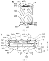
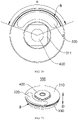
- FIG. 4 and FIG. 5 show a battery cell 45 according to an embodiment of the present application, and the battery cell 45 includes a housing 100, an end cover assembly 300 and one or more electrode assemblies 200.
- the housing 100 is shaped according to the shape of one or more electrode assemblies 200 after combination.
- the housing 100 may be a hollow cuboid or cube or cylinder, and one surface of the housing 100 has an opening so that one or more electrode assemblies 200 can be placed in the housing 100.
- the opening is hereinafter referred to as a first opening 110.
- one plane of the housing 100 is a plane with the first opening 110, and the plane is configured to have no wall body, so that the inside and outside of the housing 100 are in communication with each other.
- an end face of the housing 100 is a surface with the first opening 110, that is, the end face is configured to have no wall body, so that the inside and outside of the housing 100 are in communication with each other.
- the end cover assembly 300 covers the first opening 110 and is connected to the housing 100 to form an enclosed chamber for placing the electrode assembly 200, and the enclosed chamber is filled with electrolyte, such as the electrolytic solution.
- the end cover assembly 300 includes an end cover 310 and a pressure relief mechanism 320, the end cover 310 is used to cover the first opening 110 of the housing 100 and is connected to the housing 100, the pressure relief mechanism 320 is arranged on the end cover 310, and when an internal pressure or temperature of the battery cell 45 reaches a predetermined threshold, the pressure relief mechanism 320 performs an action or a weak structure provided in the pressure relief mechanism 320 is damaged, thereby relieving the internal pressure of the enclosed chamber.
- the battery cell 45 further includes one or more electrode terminals 400, and the electrode terminal 400 can be arranged on the end cover 310.
- the end cover 310 is generally in the shape of a flat plate, the electrode terminal 400 is fixed on a flat plate face of the end cover 310, and the electrode terminal 400 is connected with a connecting member, or may also called an current collecting plate 500, which is located between the end cover 310 and the electrode assembly 200, and is used to electrically connect the electrode assembly 200 and the electrode terminal 400.
- Each electrode assembly 200 has a first electrode tab and a second electrode tab.
- the first electrode tab and the second electrode tab have opposite polarities.
- the first electrode tab is a positive electrode tab
- the second electrode tab is a negative electrode tab.
- the first electrode tab of one or more electrode assemblies is connected to one electrode terminal through one current collecting plate, for example, a positive electrode terminal; and the second electrode tab of one or more electrode assemblies is connected to another electrode terminal through another current collecting plate, for example, a negative electrode terminal. That is, the positive electrode terminal is connected to the positive electrode tab through one current collecting plate, and the negative electrode terminal is connected to the negative electrode tab through another current collecting plate.
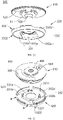
- one or more electrode assemblies 200 can be arranged according to actual use requirements. As shown in FIG. 5 , one independent electrode assembly 200 is arranged in the battery cell 45.
- the first electrode tab 210 and the second electrode tab 220 of the electrode assembly 200 can be arranged at the same end, or as shown in FIG. 6 , the first electrode tab 210 and the second electrode tab 220 of the electrode assembly 200 are arranged at two ends, respectively. That is, one end of the electrode assembly 200 is provided with the first electrode tab 210 and the other end is provided with the second electrode tab 220.
- two ends of the housing 100 of the battery cell 45 has the first opening 110, respectively, and each first opening 110 is provided with the end cover assembly 300, respectively, and the electrode terminal 400 provided in each end cover assembly 300 respectively is connected to a tab through the current collecting plate 500.
- the structure of each end cover assembly 300 and its connection structure with the housing 100 can be the same, and the following takes one end cover assembly 300 as an example for description.
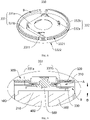
- the end cover assembly 300 further includes a first insulating member 330 and a second insulating member 340.
- the first insulating member 330 is located at a side of the end cover 310 close to the electrode assembly 200, that is, the first insulating member 330 is located between the end cover 310 and the electrode assembly 200 to isolate the electrode assembly 200 and the end cover 310.
- the second insulating member 340 is located between the end cover 310 and the electrode terminal 400 to isolate the electrode terminal 400 and the end cover 310.
- the first insulating member 330 is configured that a projection of the first insulating member 330 on the end cover 310 along a thickness direction D of the end cove covers the pressure relief mechanism 320.
- the first insulating member 330 shielding the pressure relief mechanism 320 refers that the first insulating member 330 completely shields the pressure relief mechanism 320 along the thickness direction D of the end cover, or completely shields the weak structure on the pressure relief mechanism 320, so as to prevent the weak structure of the pressure relief mechanism 320 from being damaged due to a direct impact of the electrolytic solution.
- the thickness direction D of the end cover there is also a first gap A formed between the first insulating member 330 and the pressure relief mechanism 320.
- a flow path is formed in the battery cell 45, which is used to communicate the inside of the battery cell 45 with the first gap A.
- the inside of the battery cell 45 refers to a space formed between the end cover assembly 300 and an inner wall of the housing 100 when the end cover assembly 300 covers the first opening 110 of the housing 100.
- the first insulating member 330 may be configured to be integrally spaced from the end cover 310, thereby forming the first gap A.
- the first insulating member 330 fits or abuts against the end cover 310, and another part is separated from the end cover 310 to form the first gap A.
- the first insulating member 330 forms a recess on a side facing the end cover 310, and a projection of the recess on the end cover 310 corresponds to the pressure relief mechanism 320, so that the first gap A is formed between the first insulating member 330 and the pressure relief mechanism 320.
- the end cover 310 may extend beyond the pressure relief mechanism 320 on a surface facing the first insulating member 330, so that a distance between the pressure relief mechanism 320 and the first insulating member 330 is greater than a distance between the end cover 310 and the first insulating member 330, and thus the first gap A is formed between the first insulating member 330 and the pressure relief mechanism 320.
- the current collecting plate 500 forms a avoiding space at a position corresponding to the pressure relief mechanism 320, so that the first insulating member 330 can be further away from the pressure relief mechanism 320, so as to increase the first gap A to improve a relieving effect without changing an overall occupied space of a cover plate assembly and the current collecting plate 500.
- the current collecting plate 500 includes a first connection section 510, a second connection section 520 and a third connection section 530, where the first connection section 510 connects the electrode assembly 200, the third connection section 530 connects the electrode terminal 400, and the second connection section connects the first connection section 510 and the second connection section 520.
- Creases are formed between the first connection section 510 and the second connection section 520, and between the second connection section 520 and the third connection section 530, respectively, so that the first connection section 510, the second connection section 520 and the third connection section 530 are stacked in sequence along the thickness direction D of the end cover.
- the first connection section 510, the second connection section 520 and the third connection section 530 may have different lengths.
- the length of the first connection section 510 refers to a distance from one end of the current collecting plate 500 to a crease between the first connection section 510 and the second connection section 520
- the length of the second connection section 520 refers to a distance between the crease between the first connection section 510 and the second connection section 520 and a crease between the second connection section 520 and the third connection section 530
- the length of the third connection section 530 refers to a distance from the crease between the second connection section 520 and the third connection section 530 to the other end of the current collecting plate 500.
- the length of the third connection section 530 is shorter than that of the second connection section 520, so that the third connection section 530 is stacked on the second connection section 520 to form a stepped structure.
- the first insulating member 330 includes a base wall 331 composed of a first base 331a and a second base 331b, the base wall is arranged opposite to the end cover 310, a step is formed between the first base 331a and the second base 331b, and here, the step mentioned refers that the first base 331a and the second base 331b turns at a position of connection to form two planes with a height difference.
- the first base 331a is arranged between the end cover 310 and the third connection section 530, a side of the second base 331b tightly presses a part of the second connection section 520 that is not covered by the third connection section 530, and the other side of the second base 331b is spaced from the end cover 310 to form the first gap A.
- the first insulating member 330 in the embodiment not only forms the first gap A between the second base 331b and the pressure relief mechanism 320 to ensure the safety of the battery cell 45, but also can transmit pressure through the first base 331a to tightly press the current collecting plate 500 to stabilize the assembly.
- the first insulating member 330 may not abut against the current collecting plate 500, the current collecting plate 500 may still form the stepped structure by making the third connection section 530 shorter than the second connection section 520, so that the avoiding space is formed in an area on the current collecting plate 500 corresponding to the pressure relief mechanism 320 to provide the space for forming the first gap A.
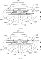
- the flow path may include a second opening B formed on the first insulating member 330 (refer to FIG. 7 ).
- a projection of the second opening B on the end cover 310 is staggered with the pressure relief mechanism 320 along the thickness direction D of the end cover 310, so that the first insulating member 330 prevent the electrolytic solution from directly impacting the pressure relief mechanism 320 when the electrolytic solution sloshes.
- the emissions enter the first gap A through the second opening B to be discharged through the pressure relief mechanism 320.
- the second opening B on the first insulating member 330 may be formed on the base wall 331 of the first insulating member 330, and its projection on the end cover 310 is staggered with the pressure relief mechanism 320.
- a penetrating direction may be along the thickness direction D of the end cover, or may also be inclined relative to the thickness direction D of the end cover and an inclination angle is less than 90°, and the penetrated hole serves as the second opening B for relieving.
- the second opening B may also be formed at the connection position of the first base 331a and the second base 331b, which is a part of the base wall 331 for connecting the first base 331a and the second base 331b with the height difference, and the part is at a certain angle with the first base 331a and the second base 331b.
- a hole penetrating from one side to the other is formed on the part, and a penetrating direction is perpendicular to the thickness direction D of the end cover, and the penetrated hole communicates the inside of the battery cell with the first gap A, which serves as the second opening for relieving.
- the second opening B When the second opening B is close to a middle position of the base wall 331, or when the second opening B is on the part of the connection position of the first base 331a and the second base 331b, the second opening B is relatively close to a tab of the electrode assembly 200, and the tab may be deformed to block the second opening B.
- the second opening B may also be formed on the outer periphery of the second base 331b, so that the second opening B is relatively far away from the tab.
- the base wall 331 is recessed from the outer periphery along a radial direction to form a gap, which serves as the second opening B for relieving.
- the first insulating member 330 further includes a side wall 332 arranged around the outer periphery of the base wall 331.
- FIG. 12 shows a top view diagram of the first insulating member 330
- FIG. 13 shows a main view diagram of the first insulating member 330.
- the side wall 332 increases the structural strength of the base wall 331, so that the base wall 331 is not easily flexed and deformed, so as to transmit the pressure in a better way, so that the end cover 310 tightly presses the current collecting plate 500 on the electrode assembly 200 through the first insulating member 330, which can effectively prevent the current collecting plate 500 and the electrode assembly 200 from dislocation under impact force or other forces, so as to avoid a loose connection between the tab, the current collecting plate 500 and the electrode terminal 400.
- the second opening B on the first insulating member 330 may also be formed on the side wall 332, at this time, the flow path further includes a second gap C formed between an outer peripheral surface of the first insulating member 330 and the inner wall of the housing 100 (refer to FIG. 7 ), and along the thickness direction D of the end cover, a projection of the second gap C on the end cover 310 along the thickness direction D of the end cover is staggered with the pressure relief mechanism 320.
- the second opening B on the side wall 332 communicates the first gap A with the second gap C, and the emissions enter the first gap A through the second opening B after entering the second gap C to be relieved from the pressure relief mechanism 320.
- the second opening B is located on the side wall 332, it is far away from the tab, and thus has an effect of not being easily blocked by the tab.
- the side wall 332 can be regarded as including a first part 332a and a second part 332b, where the first part 332a is a part connecting the first base 331a, and the second 332b is a part connecting the second base 331b; for further convenience of description, an end of the side wall 332 close to the end cover 310 is a first end 3321, and an end of the side wall 332 away from the end cover 310 is a second end 3322.
- the first end 3321 of the side wall 332 is not in contact with the end cover 310 to form the second opening B communicating the second gap C with the first gap A.
- the first end 3321 of the side wall 332 is not in contact with the end cover 310 at all, so that an annular-shaped second opening B is defined between an end face of the first end 3321 of the side wall 332 and the end cover 310.
- the first end 3321 may not protrude from the base wall 331, or the first end 3321 may protrude from the base wall 331 but not in contact with the end cover 310.
- a part of the first end 3321 of the side wall 332 is not in contact with the end cover 310, and the other part is in contact with the end cover 310, so that the second opening B is defined between an end face that the first end 3321 is not in contact with the end cover 310 and the end cover 310.
- the second opening B is at least partially located at the second part 332b of the side wall 332, so that the second opening B effectively communicates the first gap A with the second gap C.
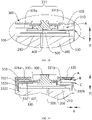
- the first end 3321 of the side wall 332 protrudes from the base wall 331 and abuts against the end cover 310, the first end 3321 of the side wall 332 is recessed towards the second end 3322 to form a groove, and the groove serves as the second opening B connecting the first gap A and the second gap C.
- the base wall 331 When the first end 3321 of the side wall 332 is only partially not in contact with the end cover 310, the base wall 331 is not easy to be deformed due to an action of the side wall 332, and the first end 3321 of the side wall 332 abuts against the end cover 310 to transmit the pressure of the end cover, so that the base wall 331 can tightly press the adaptor in a better way while the groove on the side wall 332 serves as the second opening B to meet discharge requirements.
- the second opening B is configured as a groove with a depth less than a height of the first end 3321 protruding from the base wall 331. As shown in FIG. 14 , a depth of the second opening B is h, and h is less than a height of the first end 3321 protruding from the second part 332b.
- FIG. 14 it can be seen that a lower edge of the second opening B protrudes from the base wall 331 of the first insulating member 330, so that the side wall 332 can also continuously be arranged around outer periphery of the base wall 331 with the second opening B, so that the base wall 331 has the higher structural strength, is not easy to be deformed, and can better transmit force between the end cover 310 and the current collecting plate 500 or between the end cover 310 and the electrode assembly 200.
- the second opening B on the first insulating member 330 is a hole formed by penetrating from one side of the side wall 332 to the other side, and a penetrating direction is perpendicular to the thickness direction of the end cover 310.
- part of the second opening B is located at the second part 332b, or all of that is located at the second part 332b, so that the emissions may easily enter the first gap A through the second opening B.
- the second opening B can be a polygonal hole formed through cutting on the side wall 332, or can be a circular hole formed by drilling on the side wall 332, or can be integrally formed during injection molding.
- the second opening B on the second part 332b can be arranged as a plurality, and the plurality of second openings B are arranged at intervals to reduce an influence of the second opening B on the structural strength of the side wall 332, so as to protect the base wall 331 in a better way to prevent the base wall 331 from being deformed.
- the number of the second openings B is arranged as two. In other embodiments, the number of the second openings B may also be three or four, which is not limited hereto.
- each second opening B shown in FIG. 16 are all recessed from the first end 3321 towards the second end 3322 of the side wall 332 to form the groove, but it does not mean that each second opening B should be the groove when there are the plurality of second openings B.
- a type of each second opening B may be any one of the aforementioned types.
- the flow path may only include the second gap C formed between the outer peripheral surface of the first insulating member 330 and the inner wall of the housing 100.
- a projection of the second gap C on the end cover 310 along the thickness direction D of the end cover is staggered with the pressure relief mechanism 320.
- the first insulating member does not include the side wall 332, the outer peripheral surface of the first insulating member 330 (that is, an outer peripheral surface of the base wall 331) is not in contact with the inner wall of the housing 100 at all, so as to form the second gap C.
- a part of the outer peripheral surface of the first insulating member 330 is not in contact with the inner wall of the housing 100 to form the second gap C.
- the outer peripheral surface of the first insulating member 330 at the first base 331a abuts against the inner wall of the housing 100, and the outer peripheral surface at the second base 331b is not in contact with the inner wall of the housing 100.
- the second gap C not only allows the emissions to enter the first gap A through the second gap C when the internal pressure or temperature of the battery cell 45 reaches the predetermined threshold, but also ensures that the electrolytic solution cannot pass through the second gap C to directly impact the pressure relief mechanism 320, so that the first insulating member 330 has an effect of protecting the pressure relief mechanism 320.
- an air pressure value inside the battery cell 45 and at the first gap A is equal, but in the case of out-of-control gas production or abnormal temperature rise, air pressure inside the battery cell 45 increases sharply, and if the flow path cannot discharge the air pressure timely, the gas inside the battery cell 45 cannot quickly enter the first gap A, which can easily causes that the air pressure value inside the first gap A has not yet reached a valve opening pressure value of the pressure relief mechanism 320 (that is, a pressure value that causes the pressure relief mechanism 320 to be actuated) when a pressure value inside the battery cell 45 rises to a set limit pressure value (that is, a pressure value that may cause the battery cell 45 to explode).
- a valve opening pressure value of the pressure relief mechanism 320 that is, a pressure value that causes the pressure relief mechanism 320 to be actuated
- valve opening pressure value of the pressure relief mechanism 320 is usually about one half of the limit pressure value of the battery cell 45.
- a minimum ventilation area of the flow path is configured to be greater than or equal to one half of the area of the pressure relief mechanism 320.
- the limit pressure value of the battery cell 45 is 3Mpa and the valve opening pressure value of the pressure relief mechanism 320 is 1.5Mpa in the embodiment for illustration.
- the pressure value inside the battery cell 45 is equal to the pressure value in the first gap A, and when the pressure value inside the battery cell 45 reaches 1.5Mpa, the pressure relief mechanism 320 is actuated to ensure that the pressure value inside the battery cell 45 and the pressure value in the first gap A are always at 1.5Mpa.
- the minimum ventilation area of the flow path is smaller than the area of the pressure relief mechanism 320 and is greater than one half of the area of the pressure relief mechanism 320, when the pressure value inside the battery cell 45 is greater than 1.5Mpa and less than 3Mpa, the pressure value in the first gap A reaches 1.5Mpa, so that the pressure relief mechanism 320 is actuated to prevent the battery cell 45 from exploding.
- the pressure relief mechanism 320 is actuated to prevent the battery cell 45 from exploding when the pressure value inside the battery cell 45 exceeds 3Mpa.
- the minimum ventilation area of the flow path is greater than or equal to one half of the area of the pressure relief mechanism 320: in an embodiment with the second opening B, the area of the second opening B is greater than or equal to one half of the area of the pressure relief mechanism 320; and in an embodiment with the second gap C, the minimum ventilation area of the second gap C is greater than one half of the area of the pressure relief mechanism 320.
- the minimum ventilation area of the second gap C in the embodiment refers: a cross section is made along a radial direction of the battery cell 45, when a cross-sectional area of the second gap C reaches its minimum, the cross-sectional area of the second gap C here is the minimum ventilation area.
- the outer peripheral surface of the first insulating member 330 may be in contact with the housing 100 due to manufacturing errors, which blocks the second gap C and affects a normal operation of the pressure relief mechanism 320.
- the outer peripheral surface of the first insulating member 330 is at least partially an inclined face, so that a width of the second gap C gradually increases along a direction away from the end cover 310.
- the outer peripheral surface of the first insulating member 330 is configured as the inclined face, so the second gap C forms a shape with a relatively large inlet and a relatively small outlet, which is conducive that the emissions enter the second gap C and converge under an action of the pressure and then are discharged towards the outlet.
- the second gap C has a better drainage effect, stabilizes a discharge flow path of the emissions, increases a discharge rate, and enhances a pressure relief effect.
- the second gap C extends at least from the lower edge of the second opening B to the second end 3322, and the closer the outer peripheral surface of the side wall 332 is to the second end 3322, the farther it is from the housing 100.
- the lower edge of the second opening B refers to an edge of the second opening B away from the end cover 310
- the width of the second gap C here is k, and a difference between the width of the second gap C and k gradually increases along a direction away from the end cover 310.
- the second gap C extends from the first end 3321 to the second end 3322, that is, the outer peripheral surface of the first insulating member 330 is inclined from the first end 3321 to the second end 3322, so as to further avoid blocking the second opening B caused by contact between the outer peripheral surface of the first insulating member 330 and the housing 100 due to manufacturing tolerances.
- the side wall 332 can be configured in a conical shape, and the second gap C is formed between the entire side wall 332 and the housing 100 to communicate the inside of the battery cell 45 with the first gap A.
- the side wall 332 can be configured to form the inclined face only on the outer peripheral surface of a position corresponding to the second opening B, so that the first part 332a of the side wall 332 abuts against the housing 100 to improve assembling stability of the first insulating member 330, and the second gap C is formed between the second part 332b and the housing 100 to communicate the inside of the battery cell 45 with the first gap A.
- the end cover 310 abuts against the electrode assembly 200 through the current collecting plate 500, but sometimes there is a gap between each connection section of the current collecting plate 500, causing that the electrode assembly 200 may still slosh.
- the side wall 332 is configured that the first end 3321 abuts against the end cover 310 and the second end 3322 abuts against the electrode assembly 200, so that end cover 310 directly presses the electrode assembly 200 through the side wall 332, thereby further defining a movement of the electrode assembly 200.
- the first end 3321 When the first end 3321 abuts against the end cover 310, the first end 3321 is close to a welding seam at junction of the housing 100 and the end cover 310, and when welding the housing 100 and the end cover 310, the first end 3321 of the first insulating member 330 is easy to be deformed by high heat.
- a corner at intersection of an end surface of the first end 3321 and the outer peripheral surface of the first end 3321 is chamfered or cut to be recessed from a surface of the first end 3321, so as to form a spacing between the welding seam and the first end 3321 of the side wall 332.
- the first end 3321 is not easy to be burned during a process of welding the junction of the housing 100 and the end cover 310 at high temperature to form the welding seam, which prevents the side wall 332 from being thermally deformed at the high temperature generated during the welding, solves a problem that the side wall 332 cannot abut against the end cover 310 and the electrode assembly 200 due to thermal damage and deformation, and avoids a poor constraint of the electrode assembly 200.
- a response speed of the pressure relief mechanism 320 is relatively low.
- a central angle corresponding to a projection of the second opening B or the second gap C on the end cover 310 at least partially overlaps with a part of a central angle corresponding to the pressure relief mechanism 320 along the thickness direction D of the end cover.
- a projection of the second opening B on the end cover 310 is formed in an arc, a central angle corresponding to the arc is ⁇ , and two radius of the end cover 310 pass through two ends of the arc and form a fan shape with the arc.
- the pressure relief mechanism 320 is located within a fan-shaped range, which makes a distance from the second opening B to the pressure relief mechanism 320 become shorter, and the emissions can smoothly and quickly reach the pressure relief mechanism 320 to improve the response speed of the pressure relief mechanism.
- the second opening B is taken as an example for description, and the second gap C is the same.
- a first positioning portion 311 is arranged on the end cover 310
- a second positioning portion 3311 is arranged on the base wall 331
- the first positioning portion 311 is matched with the second positioning portion 3311 to implement a peripheral positioning of the end cover 310 and the first insulating member 330.
- the first positioning portion 311 is matched with second positioning portion 3311, so that the end cover 310 and the first insulating member 330 will not stagger with each other in the radial direction and in the peripheral direction.
- the end cover assembly 300 has better stability after being assembled as a whole, and a relative position of the second opening B and the pressure relief mechanism 320 can be kept constant to ensure the response speed of the pressure relief mechanism 320, and ensure that the first insulating member 330 may totally shield the pressure relief mechanism 320 according to a preset mode.
- the end cover 310 and the first insulating member 330 can be assembled quickly and accurately through the first positioning portion 311 and the second positioning portion 3311.
- the first positioning portion 311 is a first protrusion formed on one side of the end cover 310 facing the first insulating member 330, and the second positioning portion 3311 is configured as a plurality of second protrusions on one side of the base wall 331 facing the end cover 310.
- the first protrusion is inserted between the plurality of second protrusions, and the plurality of second protrusions surround the first protrusion and match with each other to abut against the first protrusion, so as to restrict a movement of the first protrusion along a surface of the first insulating member 330, thereby restricting the movement of the end cover 310 relative to the first insulating member 330.
- the first protrusion is a polygon
- the plurality of second protrusions are arranged at corners of the polygon, respectively, and each second protrusion is configured to abut against two faces forming the corners.
- a corner of the first protrusion is chamfered to form a curved surface
- the surface of the second protrusion has the same curvature as the curved surface.
- the electrode terminal 400 is located at the first protrusion, a thickness of the end cover 310 is relatively large at the first protrusion, and by arranging the electrode terminal 400 at the first protrusion, a length of the electrode terminal 400 passing through the end cover 310 can be increased, and the assembly of the electrode terminal 400 is more stable.
- the first insulating member 330 is formed with a through hole that allows the electrode terminal 400 to pass through to connect the current collecting plate 500, and when the electrode terminal 400 is located at the first protrusion, the through hole is arranged in a range surrounded by the plurality of second protrusions for accommodating the first protrusion. That is, the plurality of second protrusions not only surround and abut against the first protrusion, but also surround a peripheral direction of the electrode terminal 400.
- the plurality of the second protrusion provides reaction force through the first protrusion at a periphery of the electrode terminal 400, and the first protrusion bears force together with the electrode terminal 400 to alleviate bend and deformation of the electrode terminal 400.
- the first positioning portion 311 may also be configured as a recess formed on one side of the end cover 310 facing the electrode assembly 200, and the recess is matched with the first protrusion on the base wall 331.
- the first positioning portion 311 may also be configured as a protrusion formed on one side of the end cover 310 facing the electrode assembly 200
- the second positioning portion 3311 is configured as a recess formed on one side of the base wall 331 facing the end cover 310.
- the second positioning portion 3311 may also be formed on the end surface of the first end 3321 of the side wall 332, and when the first end 3321 abuts against the end cover 310, the second positioning portion 3311 formed on the first end 3321 is matched with the first positioning portion 311 on the end cover 310.
- the battery cell 45, the battery 4 and the power consumption apparatus of the embodiments of the present application are described above, and a method and an apparatus for producing a battery cell 45 according to the embodiments of the present application will be described below.
- a method and an apparatus for producing a battery cell 45 according to the embodiments of the present application will be described below.
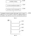
- FIG. 24 shows a schematic flowchart of a method for producing a battery cell 45 according to an embodiment of the present application, and the method can include:
- FIG. 25 shows a schematic block diagram of an apparatus 600 for producing a battery cell 45 according to an embodiment of the present application, and the apparatus 600 for producing can include: a first providing apparatus 610, a second providing apparatus 620, a third providing apparatus 630 and an assembling apparatus 640.
- the first providing apparatus 610 configured to provide a housing 100, and the housing 100 has a first opening 110;
Landscapes
- Chemical & Material Sciences (AREA)
- Chemical Kinetics & Catalysis (AREA)
- Electrochemistry (AREA)
- General Chemical & Material Sciences (AREA)
- Engineering & Computer Science (AREA)
- Manufacturing & Machinery (AREA)
- Connection Of Batteries Or Terminals (AREA)
- Sealing Battery Cases Or Jackets (AREA)
- Gas Exhaust Devices For Batteries (AREA)
Abstract
Description
- The present application relates to a field of battery technology, and in particular, to a battery cell, a battery, a power consumption apparatus, a method and an apparatus for producing a battery cell.
- In the trend of energy conservation and emission reduction, batteries are widely used in a field of new energy, such as electric vehicles, new energy vehicles, etc., and the electric vehicles have become an important part of a sustainable development of an automotive industry.
- In the development of battery technology, safety performance and service life of a battery are elements that cannot be ignored. During use of the battery, leakage often has a large adverse effect on the safety performance and service life of the battery.
- The present application aims to provide a battery cell, a battery, a power consumption apparatus, a method and an apparatus for producing a battery cell, such that a problem of battery leakage can be alleviated to improve safety performance and service life of the battery.
- In a first aspect, embodiments of the present application provide a battery cell, including:
- a housing, with a first opening;
- an electrode assembly, arranged in the housing;
- an end cover assembly, including an end cover, a pressure relief mechanism and a first insulating member, the end cover covers the first opening, the pressure relief mechanism is arranged at the end cover, the pressure relief mechanism is configured to be actuated to relieve the internal pressure of the battery cell when an internal pressure or temperature of the battery cell reaches a threshold, the first insulating member is located on a side of the end cover close to the electrode assembly to isolate the electrode assembly and the end cover, and the first insulating member is configured that a projection of the first insulating member on the end cover along a thickness direction of the end cover covers the pressure relief mechanism to protect the pressure relief mechanism.
- In the technical solution of the embodiments of the present application, the battery cell is provided with the pressure relief mechanism, and when the internal pressure or temperature of the battery cell reaches a predetermined threshold, the pressure relief mechanism is actuated to relieve the internal pressure or temperature to ensure safety of the battery cell; when the battery cell is impacted, or drops from a high place, etc., causing an electrolytic solution inside the battery cell to slosh, and the first insulating member is used to completely cover the pressure relief mechanism to prevent the pressure relief mechanism from opening or cracking due to an impact of electrolytic solution sloshing, resulting in leakage of the electrolytic solution, thereby increasing life of the battery cell.
- In an embodiment of the present application, optionally, the pressure relief mechanism and the first insulating member are provided with a first gap in the thickness direction of the end cover, the battery cell further includes a flow path, and the flow path is configured to communicate the inner portion of the battery cell with the first gap.
- When the internal pressure or temperature of the battery cell reaches the threshold, the pressure relief mechanism is actuated under the pressure, and a gas inside the battery cell reaches the first gap through the flow path to be relieved from the pressure relief mechanism, so that functions of the pressure relief mechanism can be ensured while reducing the leakage of the battery cell, thereby improving the safety of the battery cell.
- In an embodiment of the present application, optionally, the flow path includes a second opening arranged on the first insulating member, and the second opening is configured that a projection of the second opening on the end cover along the thickness direction of the end cover is staggered with the pressure relief mechanism.
- The second opening on the first insulating member enables emissions inside the battery cell to be smoothly relieved from the pressure relief mechanism. Since the second opening on the first insulating member is staggered with the pressure relief mechanism, when the electrolytic solution sloshes in the housing due to impact or drop of the battery, it can effectively prevent the electrolytic solution from impacting the pressure relief mechanism, and even if the electrolytic solution flows to the first gap from the second opening, impact force acts mainly on the end cover, and the pressure relief mechanism may not be directly impacted.
- In an embodiment of the present application, optionally, the second opening is located at an outer periphery of the first insulating member.
- When the second opening is located at the outer periphery of the first insulating member, the electrode assembly is not easy to block the second opening compared with a position arranged in the middle of the first insulating member, so as to ensure the emissions can be smoothly relieved, thereby improving the safety of the battery.
- In an embodiment of the present application, optionally, the first insulating member includes a base wall and a side wall, the base wall is arranged opposite to the end cover, the first gap is formed between the base wall and the end cover, the side wall is arranged around outer periphery of the base wall, and the second opening is arranged on the side wall.
- The side wall is arranged around the outer periphery of the base wall, which can improve a structural strength of the base wall and ensure the base wall to be not easily flexed and deformed. At the same time, since the second opening is arranged on the side wall, it can further prevent the second opening from being blocked and ensure the second opening can communicate the inner portion of the battery cell with the first gap to smoothly relieve the emissions, thereby ensuring the safety of the battery cell. In an embodiment of the present application, optionally, the side wall has a first end close to the end cover and a second end away from the end cover, and the second opening is a groove recessed by the side wall from the first end towards the second end.
- In an embodiment of the present application, optionally, the first end protrudes from the base wall, and a depth of the groove is smaller than a height of the first end protruding from the base wall.
- Since the depth of the groove is less than the height of the first end protruding from the base wall, the side wall can still maintain a state surrounding the base wall when possessing the second opening, thereby ensuring the structural strength and ensuring the base wall not easy to be deformed.
- In an embodiment of the present application, optionally, the first end abuts against the end cover, and the second end abuts against the electrode assembly.
- The end cover tightly presses the electrode assembly through the first insulating member, so that the position of the electrode assembly is restrained in an axial direction, thereby preventing the electrode assembly from sloshing in the axial direction. In an embodiment of the present application, optionally, the battery cell further includes:
- an electrode terminal, fixed at the end cover;
- an current collecting plate, including a first connection section, a second connection section and a third connection section stacked in sequence, where the first connecting section is configured to be connected with the electrode assembly, the third connection section is configured to be connected with the electrode terminal, and the second connection section is configured to connect the first connection section and the third connection section;
- the base wall includes a first base and a second base, a step is formed between the first base and the second base, the first base abuts against the third connection section, and the second base abuts against the second connection section; and
- the side wall includes a first part and a second part, the first part is connected to outer periphery surface of the first base, the second part is connected to outer periphery surface of the second base, and the second opening is arranged on the second part.
- The first connection section, the second connection section and the third connection section of the current collecting plate are stacked in sequence, where the second connection section and the third connection section form a stepped structure, so as to reverse more space at a position corresponding to the pressure relief mechanism; and the base wall forms the step, which can not only tightly press the current collecting plate, but also enlarge the position of the first gap corresponded to the second gap. By arranging as above, the first gap can be arranged as large as possible without increasing an overall thickness of the end cover assembly, so that an exhaust rate can be as high as possible when the pressure is required to be relieved, thereby improving the safety of the battery cell.
- Moreover, since the second opening is located at the second part, the first gap is relatively enlarged here, which enables the emissions in the flow path to swiftly enter the first gap, further playing the effect of rapidly relieving and improving the safety of the battery cell.
- In an embodiment of the present application, optionally, a central angle corresponded to a projection of the second opening projected on the end cover along the thickness direction of the end cover at least partially overlaps with a central angle corresponded to the pressure relief mechanism.
- In the above technical solution, a distance between the second opening and the pressure relief mechanism is relatively short, the emissions can reach the pressure relief mechanism and be discharged relatively swiftly, thereby increasing a response speed of the pressure relief mechanism.
- In an embodiment of the present application, optionally, a first positioning portion is arranged on the end cover, a second positioning portion is arranged on the base wall, and the first positioning portion is matched with the second positioning portion to implement a peripheral positioning of the end cover and the first insulating member.
- The end cover is matched with the first insulating member through the first positioning portion and the second positioning portion, which can not only implement a quick and correct assembly of the end cover and the first insulating member, but also define a relative position of the end cover and the first insulating member in a peripheral direction, so as to ensure that the second opening and the pressure relief mechanism maintain a relative positional relationship, thereby ensuring the safety and structural stability of the battery cell.
- In an embodiment of the present application, optionally, an area of the second opening is greater than or equal to one half of an area of the pressure relief mechanism.
- It is arranged that the area of the second opening is greater than or equal to one half of the area of the pressure relief mechanism, which can avoid a problem that the area of the second opening is too small to ensure a normal actuation of the pressure relief mechanism, and ensure that at least a valve opening pressure value is reached at the first gap when the internal pressure of the battery cell reaches a limit pressure value, thereby ensuring the safety of the battery cell.
- In an embodiment of the present application, optionally, the flow path comprises a second gap formed between an outer peripheral surface of the first insulating member and an inner wall of the housing, and the second gap is configured that a projection of the second gap on the end cover along the thickness direction of the end cover is staggered with the pressure relief mechanism.
- The second gap is used to directly communicate with the first gap, or the second gap communicates with the second gap through the second opening, so as to meet requirements for relieving the pressure through the pressure relief mechanism, and to prevent the electrolytic solution from impacting the pressure relief mechanism as well by staggering the second gap with the pressure relief mechanism.
- In an embodiment of the present application, optionally, a smallest ventilation area of the second gap is greater than or equal to one half of the area of the pressure relief mechanism.
- When the smallest ventilation area of the second gap is greater than or equal to one half of the pressure relief mechanism, it can effectively avoid a problem that the ventilation area of the second gap is too small to actuate that the pressure relief mechanism normally, and can ensure that the valve opening pressure value is reached at the first gap at least when the internal pressure of the battery cell reaches the limit pressure value, thereby ensuring the safety of the battery cell.
- In an embodiment of the present application, optionally, at least part of the outer peripheral surface of the first insulating member is an inclined face, so that a width of the second gap gradually increases along a direction away from the end cover.
- Since the first insulating member is configured that at least it is the inclined face at the second gap, it can not only facilitate the gas to converge into the second gap and enter the first gap to be relieved, but also avoid second gap blockage due to an interference between the first insulating member and the inner wall of the housing caused by manufacturing tolerances. In addition, a condition of an interference between the end cover assembly and the inner wall of the housing can be reduced when the end cover assembly is assembled to the second opening of the housing.
- In a second aspect, the embodiments of the present application provides a battery, including the aforementioned battery cell.
- For the battery provided by the embodiment, each battery cell inside the battery respectively has a pressure relief mechanism to ensure the safety, and the pressure relief mechanism is not easily damaged when each battery cell is impacted or drops. Overall durability and safety performance of the battery are good.
- In a third aspect, the embodiments of the present application provide a power consumption apparatus, including the aforementioned battery, and the battery is configured to provide electrical energy.
- The power consumption apparatus provided in the embodiment is installed with a battery with good anti-fall performance, durability performance and safety performance, and power supply reliability of the battery is high. The power consumption apparatus has effects of stable operation, high safety and good durability.
- In a fourth aspect, the embodiments of the present application provides a method for producing a battery cell, including:
- providing a housing, and the housing has a first opening;
- providing an electrode assembly;
- providing an end cover assembly, the end cover assembly includes an end cover, a pressure relief mechanism and a first insulating member, the pressure relief mechanism is arranged at the end cover, and the pressure relief pressure mechanism is configured to be actuated to relieve the internal pressure of the battery cell when an internal pressure or temperature of the battery cell reaches a threshold, the first insulating member is located on a side of the end cover, and the first insulating member is configured that a projection of the first insulating member on the end cover along a thickness direction of the end cover covers the pressure relief mechanism to protect the pressure relief mechanism; and
- placing the electrode assembly in the housing, and covering the end cover at the first opening, so that the first insulating member is located on a side of the end cover close to the electrode assembly to isolate the electrode assembly and the end cover.
- In a fifth aspect, the embodiments of the present application provides an apparatus for producing a battery cell, including:
- a first providing, configured apparatus to provide a housing, and the housing has a first opening;
- a second providing apparatus, configured to providing an electrode assembly;
- a third providing apparatus, configured to provide an end cover assembly, the end cover assembly includes an end cover, a pressure relief mechanism and a first insulating member, the pressure relief mechanism is arranged on the end cover, the pressure relief mechanism is configured to be actuated to relieve the internal pressure of the battery cell when an internal pressure or temperature of the battery cell reaches a threshold, the first insulating member is located on a side of the end cover, and the first insulating member is configured that a projection of the first insulating member on the end cover along a thickness direction of the end cover covers the pressure relief mechanism to protect the pressure relief mechanism; and
- an assembling apparatus, configured to place the electrode assembly in the housing, and cover the end cover over the first opening, so that the first insulating member is located on a side of the end cover close to the electrode assembly to isolate the electrode assembly and the end cover.
- The above description is only an overview of the technical solution of the embodiments of the present application. In order to better understand the technical means of the embodiments of the present application, it can be implemented in accordance with the content of the description, and in order to make the above and other objectives, features and advantages of the embodiments of the present application more obvious and mobile, the specific embodiments of the present application is given as follows.
- In order to illustrate the technical solution in the embodiments of the present application more clearly, brief description will be made below to the drawings required in the embodiments of the present application. Apparently, the drawings described below are some embodiments of the present application only, and other drawings could be obtained based on these drawings by those ordinary skilled in this field without creative efforts.
-
FIG. 1 is a schematic diagram of a vehicle provided by an embodiment of the present application; -
FIG. 2 is a structural schematic diagram of a battery provided by an embodiment of the present application; -
FIG. 3 is an exploded view of a battery module provided by an embodiment of the present application; -
FIG. 4 is a cross-sectional view of a battery cell provided by an embodiment of the present application; -
FIG. 5 is an exploded view of a battery cell provided by an embodiment of the present application; -
FIG. 6 is a cross-sectional view of a battery cell along it axis provided by an embodiment of the present application; -
FIG. 7 is an enlarged view of a portion VI ofFIG. 6 ; -
FIG. 8 is a structural schematic diagram of a first insulating member provided by an embodiment of the present application; -
FIG. 9 is a schematic diagram of a second opening of a first insulating member provided by another embodiment of the present application; -
FIG. 10 is a schematic diagram of another second opening of a first insulating member provided by another embodiment of the present application; -
FIG. 11 is a schematic diagram of yet another second opening of a first insulating member provided by another embodiment of the present application; -
FIG. 12 is a top view diagram of a first insulating member provided by an embodiment of the present application; -
FIG. 13 is a main view diagram of a first insulating member provided by an embodiment of the present application; -
FIG 14 is a cross-sectional schematic diagram of a first insulating member along XII-XII ofFIG. 12 ; -
FIG. 15 is a schematic diagram of another second opening of a first insulating member provided by an embodiment of the present application; -
FIG. 16 is a structural schematic diagram of a first insulating member with a plurality of second openings provided by an embodiment of the present application; -
FIG. 17 is a structural schematic diagram of a first insulating member provided by yet another embodiment of the present application; -
FIG. 18 is a structural schematic diagram of another second gap of a first insulating member provided by yet another embodiment of the present application; -
FIG. 19 is a partial schematic diagram of a battery cell cut along its axis provided by an embodiment of the present application; -
FIG. 20 is a schematic diagram of a projection of a second opening on an end cover provided by an embodiment of the present application; -
FIG. 21 is a structural schematic diagram of an end cover assembly provided by an embodiment of the present application; -
FIG. 22 is an exploded view of an end cover assembly in a perspective provided by an embodiment of the present application; -
FIG. 23 is an exploded view of an end cover assembly in another perspective provided by an embodiment of the present application; -
FIG. 24 is a schematic flowchart of a method for producing a battery cell provided by an embodiment of the present application; -
FIG. 25 is a schematic block diagram of an apparatus for producing a battery cell provided by an embodiment of the present application. - In the accompanying drawings, the drawings are not drawn to actual scale.
- To make the objectives, technical solutions and advantages of the embodiments of the present application become clearer, the following clearly describes the technical solutions in the embodiments of the present application with reference to the drawings in the embodiments of the present application. Apparently, the described embodiments are part but not all of the embodiments of the present application. All the other embodiments obtained by those of ordinary skill in the art based on the embodiments of the present application without any inventive effort shall fall within the scope of protection of the present application.
- Unless otherwise defined, all technical and scientific terms used in the present application have the same meanings as those commonly understood by those skilled in the art to which the present application belongs. The terms used in the specification of the present application are merely for the purpose of describing specific embodiments, but are not intended to limit the present application. The terms "including" and "having" and any variations thereof in the specification and the claims of the present application as well as the foregoing description of the drawings are intended to cover non-exclusive inclusions. The terms "first", "second" and the like in the specification and the claims of the present application as well as the above drawings are used to distinguish different objects, rather than to describe a specific order or primary-secondary relationship.
- The phrase "embodiments" referred in the present application means that the descriptions of specific features, structures, and characteristics in combination with the embodiments are included in at least one embodiment of the present application. The phrase at various locations in the specification does not necessarily refer to the same embodiment, or an independent or alternative embodiment exclusive of another embodiment. Those skilled in the art understand, in explicit or implicit manners, that an embodiment described in the present application may be combined with other embodiments.
- In the description of the present application, it should be noted that unless otherwise explicitly specified and defined, the terms "mounting", "connecting", "connection" and "attaching" should be understood in a broad sense, for example, they may be a fixed connection, also a detachable connection, or an integrated connection; may be a direct connection or may also be an indirect connection via an intermediate medium, or may be communication between the inner portion of two elements. Those of ordinary skill in the art may appreciate a specific meaning of the foregoing terms in the present application according to a specific circumstance.
- In the present application, the term "and/or" is only an associated relationship describing associated objects, which means that there may be three relationships. For example, A and/or B may represent three situations: Only A exists, or both A and B exist, or only B exists. In addition, the character "/" in the present application generally indicates that the associated objects before and after the character are in an "or" relationship.
- In the embodiments of the present application, same components are denoted by same reference numerals, and detailed description of the same component is omitted in different embodiments for brevity. It should be understood that dimensions such as thicknesses, lengths and widths of various components in embodiments of the present application shown in the drawings, as well as dimensions of the overall thickness, length and width of an integrated apparatus are merely illustrative, and should not constitute any limitation to the present application.
- In the present application, "a plurality of' means two or more (including two), similarly, "a plurality of groups" means two or more groups (including two groups), and "a plurality of sheets" means two or more sheets (including two sheets).
- In the present application, battery cells may include lithium-ion secondary batteries, lithium-ion primary batteries, lithium-sulfur batteries, sodium-lithium-ion batteries, sodium-ion batteries or magnesium-ion batteries, etc., which are not limited by the embodiments of the present application. The battery cell may be cylindrical, flat, cuboid or other shapes, which are not limited by the embodiments of the present application as well. The battery cell is generally divided into three types according to the way of packaging: a cylindrical battery cell, a prismatic battery cell and a soft package battery cells, which are not limited by the embodiments of the present application as well.
- The battery mentioned in the embodiment of the present application refers to a single physical module that includes one or more battery cells to provide a higher voltage and capacity. For example, the battery mentioned in the present application may include a battery module, a battery pack or the like. The battery generally includes a box body for enclosing one or more battery cells. The box body may prevent liquid or other foreign matters from affecting the charging or discharging of the battery cell.
- The battery cells includes an electrode assembly and an electrolytic solution, and the electrode assembly is composed of a positive electrode sheet, a negative electrode sheet and a separator. The operation of the battery cell mainly relies on the movement of metal ions between the positive electrode sheet and the negative electrode sheet. The positive electrode sheet includes a positive electrode current collector and a positive electrode active material layer. The positive electrode active material layer is coated on a surface of the positive electrode current collector, a current collector not coated with the positive electrode active material layer protrudes from a current collector coated with the positive electrode active material layer, and the current collector not coated with the positive electrode active material layer is used as a positive electrode tab. As an example, in a lithium-ion battery, a material of the positive electrode current collector may be aluminum, and the positive electrode active material may be lithium cobalt oxides, lithium iron phosphate, ternary lithium, lithium manganate, or the like. The negative electrode sheet includes a negative electrode current collector and a negative electrode active material layer. The negative electrode active material layer is coated on a surface of the negative electrode current collector, a current collector not coated with the negative electrode active material layer protrudes from a current collector coated with the negative electrode active material layer, and the current collector not coated with the negative electrode active material layer is used as a negative electrode tab. A material of the negative electrode current collector may be copper, and the negative electrode active material may be carbon, silicon, or the like. In order to ensure that no fusing occurs when a large current passes, there are a plurality of positive electrode tabs which are stacked together, and there are a plurality of negative electrode tabs which are stacked together. A material of the separator may be PP, PE, or the like. In addition, the electrode assembly may be a winding structure or a laminated structure, and the embodiments of the present application are not limited thereto. With the development of battery technology, it is necessary to consider many design factors at the same time, such as energy density, cycle life, discharge capacity, charge-discharge rate and other performance parameters. In addition, safety of batteries should also be considered.
- With regard to the battery cell, main safety hazards come from charging and discharging processes, and a suitable environmental temperature design is also required. In order to effectively avoid unnecessary losses, at least triple protecting measures are generally adopted for the battery cell. Specifically, the protecting measures include at least a switching element, a properly selected separator material and a pressure relief mechanism. The switching element refers to an element that can stop the charging or discharging of the battery when the temperature or resistance in a battery cell reaches a certain threshold. The separator is used to isolate the positive electrode sheet from the negative electrode sheet and can automatically dissolve micron-sized (or even nanoscale) micro-pores attached to the separator when the temperature rises to a certain value, thereby preventing metal ions from passing through the separator , terminating an internal reaction of the battery cell.
- The pressure relief mechanism refers to an element or a component that is actuated to relieve an internal pressure or temperature when the internal pressure or temperature of the battery cell reaches a predetermined threshold. The threshold design is different according to different design requirements. The threshold may depend on materials of one or more of the positive electrode sheet, the negative electrode sheet, the electrolytic solution and the separator in the battery cell.
- The "actuate" mentioned in the present application refers that the pressure relief mechanism produces an action or is activated to a certain state, so that the internal pressure and temperature of the battery cell can be relieved. The action produced by the pressure relief mechanism may include but be not limited to: at least a portion of the pressure relief mechanism being fractured, broken, torn or opened, and so on. When the pressure relief mechanism is actuated, high-temperature and high-pressure substances inside the battery cell are discharged outwards from an actuated position as emissions. In this way, the pressure in the battery cell can be relieved at a controllable pressure or temperature, thereby avoiding potentially more serious accidents.
- The emissions from the battery cell mentioned in the present application include but are not limited to: the electrolytic solution, the dissolved or split positive and negative electrode sheets, fragments of the separator, high-temperature and high-pressure gas generated by reaction, flame, etc.
- The pressure relief mechanism on the battery cell has an important effect on the safety of the battery. For example, when short circuit, overcharge and other phenomena occurs, it may lead to thermal runaway inside the battery cell, resulting in a sudden increase of pressure or temperature. In this case, the internal pressure and temperature may be released outwards through the actuation of the pressure relief mechanism, to prevent the battery cell from exploding and catching fire.
- The pressure relief mechanism may take the form of an anti-explosion valve, an air valve, a pressure relief valve, a safety valve or the like, and may specifically adopt a pressure-sensitive or temperature-sensitive element or structure. That is, when the internal pressure or temperature of the battery cell reaches the predetermined threshold, the pressure relief mechanism performs an action or a weakened structure provided in the pressure relief mechanism is damaged, so as to form a through opening or a channel for relieving the internal pressure or temperature.
- The battery cell sometimes leaks during use. When the battery cell leaks, it means that the battery cell cannot work normally, thereby affecting life of the battery cell. The inventor researched and discovered that a leakage often occurs at the pressure relief mechanism, and even if there is no abnormal gas production or high temperature problem in the battery cell, the pressure relief mechanism may also leak. After leaking, the inventor exchanged a pressure relief mechanism with better quality, but the problem of the leakage cannot be solved. Therefore, the inventor further researched and discovered that when the battery cell is impacted or drops, the electrolytic solution may slosh inside the battery cell and then impact the pressure relief mechanism, so that the pressure relief mechanism is opened, damaged or cracked, resulting in the leakage of the electrolytic solution. Even when the electrolytic solution impacts the pressure relief mechanism, the pressure relief mechanism does not produce obvious damages, but only produces hard-to-observe cracks, which may also reduce the structural strength of the pressure relief mechanism. In the subsequent use process, an abnormal situation may occur in which the internal pressure of the battery cell is within a normal range but the pressure relief mechanism is actuated, thereby reducing the safety and service life of the battery cell.
- In view of this, in order to enhance the safety and service life of the battery cell, the embodiments of the present application provide a technical solution, that is, a protective structure for shielding the pressure relief mechanism is arranged at a position corresponding to the pressure relief mechanism of the battery cell, and when the electrolytic solution inside the battery cell sloshes, the protective structure blocks impulse towards the pressure relief mechanism, so as to avoid the damages to the pressure relief mechanism, thereby further solving a problem of the reduced safety and service life of the battery cell caused by the leakage.
- The technical solution described in the embodiments of the present application are all applicable to various devices using batteries, such as mobile phones, portable apparatuses, notebook computers, electromobiles, electric toys, electric tools, electric vehicles, ships, spacecrafts and so on. For example, the spacecrafts include airplanes, rockets, space shuttles, spaceships and so on.
- It should be understood that the technical solution described in the embodiments of the present application are not only applicable to the devices described above, but also applicable to all devices using batteries. However, for ease of description, the following embodiments are all described by an example of an electric vehicle.
- For example, as shown in
FIG. 1, FIG. 1 is avehicle 1 according to an embodiment of the present application. Thevehicle 1 may be a fuel-powered vehicle, a gas-powered vehicle or an alternative fuel vehicle, and the new energy vehicle may be a battery electric vehicle, a hybrid vehicle, an extended-range vehicle, or the like. Amotor 2, a controller 3 and abattery 4 may be arranged inside thevehicle 1, and the controller 3 is used to control thebattery 4 to supply power to themotor 2. For example, thebattery 4 may be disposed at the bottom, head or tail of thevehicle 1. Thebattery 4 may be used for supplying power of thevehicle 1. For example, thebattery 4 may serve as an operation power source of thevehicle 1 for a circuit system of thevehicle 1, for example, for a working power demand of thevehicle 1 during startup, navigation and run. In another embodiment of the present application, thebattery 4 may serve not only as an operating power source of thevehicle 1, but also as a driving power source of thevehicle 1, replacing or partially replacing fuel or natural gas to provide driving power for thevehicle 1. - In order to meet different power demands, the
battery 4 may include a plurality of battery cells, where the plurality of battery cells may be in series connection, parallel connection or series-parallel connection. The series-parallel connection refers to a combination of series connection and parallel connection. Thebattery 4 may also be called a battery pack. Optionally, please be shown in a combination withFIG. 2 andFIG. 3 , a plurality of battery cells may be first connected in series, in parallel or in series-parallel to form abattery module 41, and then a plurality ofbattery modules 41 are connected in series, in parallel or in series-parallel to form thebattery 4. That is, the plurality of battery cells may directly form thebattery 4, or may first form thebattery module 41, and then thebattery modules 41 form thebattery 4. - The
battery 4 may include a plurality of battery cells. Thebattery 4 may further include a box body 42 (or a covering). The inner portion of thebox body 42 is a hollow structure, and the plurality of battery cells are accommodated in thebox body 42. Thebox body 42 may include two parts for accommodation (refer toFIG. 2 ), which are referred herein as a cover body 34 and alower box body 44, respectively, and thecover body 43 and thelower box body 44 are buckled together. The shapes of thecover body 43 and thelower box body 44 may be determined according to the shape of the combined plurality of battery cells, and both thecover body 43 and thelower box body 44 can have an opening. For example, thecover body 43 and thelower box body 44 each can be a hollow cuboid and only one surface of each is an opening surface, and the opening of thecover body 43 is arranged opposite to the opening of thelower box body 44, and thecover body 43 and thelower box body 44 are buckled to each other to form thebox body 42 with a closed chamber. One of thecover body 43 and thelower box body 44 can also be a cuboid with an opening, and the other is a cover structure to enclose the opening of the cuboid. The plurality of battery cells are combined in parallel connection or series connection or series-parallel connection and are then placed in thebox body 42 formed by buckling thecover body 43 to thelower box body 44. - Optionally, the
battery 4 may also include other structures. For example, thebattery 4 may also include a busbar. The busbar is used to implement an electrical connection between the plurality ofbattery cells 45, such as parallel connection, series connection or series-parallel connection. Specifically, the busbar can realized the electrical connection between thebattery cells 45 by connecting electrode terminals of thebattery cells 45. Furthermore, the busbar can be fixed to the electrode terminals of thebattery cells 45 by means of welding. Electrical energy of the plurality ofbattery cells 45 can be further led out through an electrically conductive mechanism passing through thebox body 42. Optionally, the electrically conductive mechanism may also belong to the busbar. - Any
battery cell 45 is described in detail in the following.FIG. 4 andFIG. 5 show abattery cell 45 according to an embodiment of the present application, and thebattery cell 45 includes ahousing 100, anend cover assembly 300 and one ormore electrode assemblies 200. Thehousing 100 is shaped according to the shape of one ormore electrode assemblies 200 after combination. For example, thehousing 100 may be a hollow cuboid or cube or cylinder, and one surface of thehousing 100 has an opening so that one ormore electrode assemblies 200 can be placed in thehousing 100. For convenience of description, the opening is hereinafter referred to as afirst opening 110. For example, when thehousing 100 is a hollow cuboid or cube, one plane of thehousing 100 is a plane with thefirst opening 110, and the plane is configured to have no wall body, so that the inside and outside of thehousing 100 are in communication with each other. When thehousing 100 is a hollow cylinder, an end face of thehousing 100 is a surface with thefirst opening 110, that is, the end face is configured to have no wall body, so that the inside and outside of thehousing 100 are in communication with each other. Theend cover assembly 300 covers thefirst opening 110 and is connected to thehousing 100 to form an enclosed chamber for placing theelectrode assembly 200, and the enclosed chamber is filled with electrolyte, such as the electrolytic solution. - The
end cover assembly 300 includes anend cover 310 and apressure relief mechanism 320, theend cover 310 is used to cover thefirst opening 110 of thehousing 100 and is connected to thehousing 100, thepressure relief mechanism 320 is arranged on theend cover 310, and when an internal pressure or temperature of thebattery cell 45 reaches a predetermined threshold, thepressure relief mechanism 320 performs an action or a weak structure provided in thepressure relief mechanism 320 is damaged, thereby relieving the internal pressure of the enclosed chamber. - The
battery cell 45 further includes one ormore electrode terminals 400, and theelectrode terminal 400 can be arranged on theend cover 310. Theend cover 310 is generally in the shape of a flat plate, theelectrode terminal 400 is fixed on a flat plate face of theend cover 310, and theelectrode terminal 400 is connected with a connecting member, or may also called ancurrent collecting plate 500, which is located between theend cover 310 and theelectrode assembly 200, and is used to electrically connect theelectrode assembly 200 and theelectrode terminal 400. - Each
electrode assembly 200 has a first electrode tab and a second electrode tab. The first electrode tab and the second electrode tab have opposite polarities. For example, when the first electrode tab is a positive electrode tab, the second electrode tab is a negative electrode tab. The first electrode tab of one or more electrode assemblies is connected to one electrode terminal through one current collecting plate, for example, a positive electrode terminal; and the second electrode tab of one or more electrode assemblies is connected to another electrode terminal through another current collecting plate, for example, a negative electrode terminal. That is, the positive electrode terminal is connected to the positive electrode tab through one current collecting plate, and the negative electrode terminal is connected to the negative electrode tab through another current collecting plate. - In the
battery cell 45, one ormore electrode assemblies 200 can be arranged according to actual use requirements. As shown inFIG. 5 , oneindependent electrode assembly 200 is arranged in thebattery cell 45. - The
first electrode tab 210 and thesecond electrode tab 220 of theelectrode assembly 200 can be arranged at the same end, or as shown inFIG. 6 , thefirst electrode tab 210 and thesecond electrode tab 220 of theelectrode assembly 200 are arranged at two ends, respectively. That is, one end of theelectrode assembly 200 is provided with thefirst electrode tab 210 and the other end is provided with thesecond electrode tab 220. Correspondingly, two ends of thehousing 100 of thebattery cell 45 has thefirst opening 110, respectively, and eachfirst opening 110 is provided with theend cover assembly 300, respectively, and theelectrode terminal 400 provided in eachend cover assembly 300 respectively is connected to a tab through thecurrent collecting plate 500. The structure of eachend cover assembly 300 and its connection structure with thehousing 100 can be the same, and the following takes oneend cover assembly 300 as an example for description. - As shown in
FIG. 7 , theend cover assembly 300 further includes a first insulatingmember 330 and a second insulatingmember 340. The first insulatingmember 330 is located at a side of theend cover 310 close to theelectrode assembly 200, that is, the first insulatingmember 330 is located between theend cover 310 and theelectrode assembly 200 to isolate theelectrode assembly 200 and theend cover 310. The second insulatingmember 340 is located between theend cover 310 and theelectrode terminal 400 to isolate theelectrode terminal 400 and theend cover 310. - The first insulating
member 330 is configured that a projection of the first insulatingmember 330 on theend cover 310 along a thickness direction D of the end cove covers thepressure relief mechanism 320. When thebattery cell 45 is impacted or drops, resulting in the internal electrolytic solution sloshing in thehousing 100 and impacting towards theend cover 310, the first insulatingmember 330 blocks the electrolytic solution and bears the impact instead of thepressure relief mechanism 320, thereby protecting thepressure relief mechanism 320 to prevent thepressure relief mechanism 320 from being damaged. - In the present application, the first insulating
member 330 shielding thepressure relief mechanism 320 refers that the first insulatingmember 330 completely shields thepressure relief mechanism 320 along the thickness direction D of the end cover, or completely shields the weak structure on thepressure relief mechanism 320, so as to prevent the weak structure of thepressure relief mechanism 320 from being damaged due to a direct impact of the electrolytic solution. - In order to take into account the safety of the
battery cell 45, in the thickness direction D of the end cover, there is also a first gap A formed between the first insulatingmember 330 and thepressure relief mechanism 320. At the same time, a flow path is formed in thebattery cell 45, which is used to communicate the inside of thebattery cell 45 with the first gap A. When thepressure relief mechanism 320 is actuated, the emissions such as gas inside thebattery cell 45 can reach the first gap A through the flow path, and can be relieved from thepressure relief mechanism 320 to the outside of thebattery cell 45. - The inside of the
battery cell 45 refers to a space formed between theend cover assembly 300 and an inner wall of thehousing 100 when theend cover assembly 300 covers thefirst opening 110 of thehousing 100. In the present application, there is a space accommodating theelectrode assembly 200 enclosed by the first insulatingmember 330 and thehousing 100. - The first insulating
member 330 may be configured to be integrally spaced from theend cover 310, thereby forming the first gap A. - Or, a part of the first insulating
member 330 fits or abuts against theend cover 310, and another part is separated from theend cover 310 to form the first gap A. In some embodiments, the first insulatingmember 330 forms a recess on a side facing theend cover 310, and a projection of the recess on theend cover 310 corresponds to thepressure relief mechanism 320, so that the first gap A is formed between the first insulatingmember 330 and thepressure relief mechanism 320. - In some embodiments, the
end cover 310 may extend beyond thepressure relief mechanism 320 on a surface facing the first insulatingmember 330, so that a distance between thepressure relief mechanism 320 and the first insulatingmember 330 is greater than a distance between theend cover 310 and the first insulatingmember 330, and thus the first gap A is formed between the first insulatingmember 330 and thepressure relief mechanism 320. - In some embodiments, the
current collecting plate 500 forms a avoiding space at a position corresponding to thepressure relief mechanism 320, so that the first insulatingmember 330 can be further away from thepressure relief mechanism 320, so as to increase the first gap A to improve a relieving effect without changing an overall occupied space of a cover plate assembly and thecurrent collecting plate 500. - Please refer to
FIG. 7 again, thecurrent collecting plate 500 includes afirst connection section 510, asecond connection section 520 and athird connection section 530, where thefirst connection section 510 connects theelectrode assembly 200, thethird connection section 530 connects theelectrode terminal 400, and the second connection section connects thefirst connection section 510 and thesecond connection section 520. - Creases are formed between the
first connection section 510 and thesecond connection section 520, and between thesecond connection section 520 and thethird connection section 530, respectively, so that thefirst connection section 510, thesecond connection section 520 and thethird connection section 530 are stacked in sequence along the thickness direction D of the end cover. Thefirst connection section 510, thesecond connection section 520 and thethird connection section 530 may have different lengths. Here, the length of thefirst connection section 510 refers to a distance from one end of thecurrent collecting plate 500 to a crease between thefirst connection section 510 and thesecond connection section 520, the length of thesecond connection section 520 refers to a distance between the crease between thefirst connection section 510 and thesecond connection section 520 and a crease between thesecond connection section 520 and thethird connection section 530, and the length of thethird connection section 530 refers to a distance from the crease between thesecond connection section 520 and thethird connection section 530 to the other end of thecurrent collecting plate 500. Among them, the length of thethird connection section 530 is shorter than that of thesecond connection section 520, so that thethird connection section 530 is stacked on thesecond connection section 520 to form a stepped structure. - As shown in a combination with
FIG. 7 andFIG. 8 , the first insulatingmember 330 includes abase wall 331 composed of afirst base 331a and asecond base 331b, the base wall is arranged opposite to theend cover 310, a step is formed between thefirst base 331a and thesecond base 331b, and here, the step mentioned refers that thefirst base 331a and thesecond base 331b turns at a position of connection to form two planes with a height difference. Thefirst base 331a is arranged between theend cover 310 and thethird connection section 530, a side of thesecond base 331b tightly presses a part of thesecond connection section 520 that is not covered by thethird connection section 530, and the other side of thesecond base 331b is spaced from theend cover 310 to form the first gap A. - The first insulating
member 330 in the embodiment not only forms the first gap A between thesecond base 331b and thepressure relief mechanism 320 to ensure the safety of thebattery cell 45, but also can transmit pressure through thefirst base 331a to tightly press thecurrent collecting plate 500 to stabilize the assembly. - In some embodiments, the first insulating
member 330 may not abut against thecurrent collecting plate 500, thecurrent collecting plate 500 may still form the stepped structure by making thethird connection section 530 shorter than thesecond connection section 520, so that the avoiding space is formed in an area on thecurrent collecting plate 500 corresponding to thepressure relief mechanism 320 to provide the space for forming the first gap A. - In some embodiments, the flow path may include a second opening B formed on the first insulating member 330 (refer to
FIG. 7 ). A projection of the second opening B on theend cover 310 is staggered with thepressure relief mechanism 320 along the thickness direction D of theend cover 310, so that the first insulatingmember 330 prevent the electrolytic solution from directly impacting thepressure relief mechanism 320 when the electrolytic solution sloshes. When the internal pressure or temperature of thebattery cell 45 reaches the predetermined threshold, the emissions enter the first gap A through the second opening B to be discharged through thepressure relief mechanism 320. - The second opening B on the first insulating
member 330 may be formed on thebase wall 331 of the first insulatingmember 330, and its projection on theend cover 310 is staggered with thepressure relief mechanism 320. - For example, as shown in
FIG. 9 , at a position close to the middle of the base wall 331 (that is, a position away from outer periphery of the base wall 331), a hole is formed on thesecond base 331b penetrating from one side to the other, a penetrating direction may be along the thickness direction D of the end cover, or may also be inclined relative to the thickness direction D of the end cover and an inclination angle is less than 90°, and the penetrated hole serves as the second opening B for relieving. - The second opening B may also be formed at the connection position of the
first base 331a and thesecond base 331b, which is a part of thebase wall 331 for connecting thefirst base 331a and thesecond base 331b with the height difference, and the part is at a certain angle with thefirst base 331a and thesecond base 331b. As shown inFIG. 10 , a hole penetrating from one side to the other is formed on the part, and a penetrating direction is perpendicular to the thickness direction D of the end cover, and the penetrated hole communicates the inside of the battery cell with the first gap A, which serves as the second opening for relieving. - When the second opening B is close to a middle position of the
base wall 331, or when the second opening B is on the part of the connection position of thefirst base 331a and thesecond base 331b, the second opening B is relatively close to a tab of theelectrode assembly 200, and the tab may be deformed to block the second opening B. In some embodiments, the second opening B may also be formed on the outer periphery of thesecond base 331b, so that the second opening B is relatively far away from the tab. As shown inFIG. 11 , thebase wall 331 is recessed from the outer periphery along a radial direction to form a gap, which serves as the second opening B for relieving. - In an embodiment provided by the present application, the first insulating
member 330 further includes aside wall 332 arranged around the outer periphery of thebase wall 331.FIG. 12 shows a top view diagram of the first insulatingmember 330, andFIG. 13 shows a main view diagram of the first insulatingmember 330. Theside wall 332 increases the structural strength of thebase wall 331, so that thebase wall 331 is not easily flexed and deformed, so as to transmit the pressure in a better way, so that theend cover 310 tightly presses thecurrent collecting plate 500 on theelectrode assembly 200 through the first insulatingmember 330, which can effectively prevent thecurrent collecting plate 500 and theelectrode assembly 200 from dislocation under impact force or other forces, so as to avoid a loose connection between the tab, thecurrent collecting plate 500 and theelectrode terminal 400. - In some embodiments, the second opening B on the first insulating
member 330 may also be formed on theside wall 332, at this time, the flow path further includes a second gap C formed between an outer peripheral surface of the first insulatingmember 330 and the inner wall of the housing 100 (refer toFIG. 7 ), and along the thickness direction D of the end cover, a projection of the second gap C on theend cover 310 along the thickness direction D of the end cover is staggered with thepressure relief mechanism 320. The second opening B on theside wall 332 communicates the first gap A with the second gap C, and the emissions enter the first gap A through the second opening B after entering the second gap C to be relieved from thepressure relief mechanism 320. When the second opening B is located on theside wall 332, it is far away from the tab, and thus has an effect of not being easily blocked by the tab. - For convenience of description, the
side wall 332 can be regarded as including afirst part 332a and asecond part 332b, where thefirst part 332a is a part connecting thefirst base 331a, and the second 332b is a part connecting thesecond base 331b; for further convenience of description, an end of theside wall 332 close to theend cover 310 is afirst end 3321, and an end of theside wall 332 away from theend cover 310 is asecond end 3322. - In some embodiments, the
first end 3321 of theside wall 332 is not in contact with theend cover 310 to form the second opening B communicating the second gap C with the first gap A. For example, thefirst end 3321 of theside wall 332 is not in contact with theend cover 310 at all, so that an annular-shaped second opening B is defined between an end face of thefirst end 3321 of theside wall 332 and theend cover 310. At this time, thefirst end 3321 may not protrude from thebase wall 331, or thefirst end 3321 may protrude from thebase wall 331 but not in contact with theend cover 310. - In other embodiments, a part of the
first end 3321 of theside wall 332 is not in contact with theend cover 310, and the other part is in contact with theend cover 310, so that the second opening B is defined between an end face that thefirst end 3321 is not in contact with theend cover 310 and theend cover 310. And the second opening B is at least partially located at thesecond part 332b of theside wall 332, so that the second opening B effectively communicates the first gap A with the second gap C. - As shown in
FIG. 14 , thefirst end 3321 of theside wall 332 protrudes from thebase wall 331 and abuts against theend cover 310, thefirst end 3321 of theside wall 332 is recessed towards thesecond end 3322 to form a groove, and the groove serves as the second opening B connecting the first gap A and the second gap C. - When the
first end 3321 of theside wall 332 is only partially not in contact with theend cover 310, thebase wall 331 is not easy to be deformed due to an action of theside wall 332, and thefirst end 3321 of theside wall 332 abuts against theend cover 310 to transmit the pressure of the end cover, so that thebase wall 331 can tightly press the adaptor in a better way while the groove on theside wall 332 serves as the second opening B to meet discharge requirements. - In order to take into account a relieving function and the structural strength of the first insulating
member 330, the second opening B is configured as a groove with a depth less than a height of thefirst end 3321 protruding from thebase wall 331. As shown inFIG. 14 , a depth of the second opening B is h, and h is less than a height of thefirst end 3321 protruding from thesecond part 332b. - In
FIG. 14 , it can be seen that a lower edge of the second opening B protrudes from thebase wall 331 of the first insulatingmember 330, so that theside wall 332 can also continuously be arranged around outer periphery of thebase wall 331 with the second opening B, so that thebase wall 331 has the higher structural strength, is not easy to be deformed, and can better transmit force between theend cover 310 and thecurrent collecting plate 500 or between theend cover 310 and theelectrode assembly 200. - In yet another embodiments, as shown in
FIG. 15 , the second opening B on the first insulatingmember 330 is a hole formed by penetrating from one side of theside wall 332 to the other side, and a penetrating direction is perpendicular to the thickness direction of theend cover 310. In this case, part of the second opening B is located at thesecond part 332b, or all of that is located at thesecond part 332b, so that the emissions may easily enter the first gap A through the second opening B. - The second opening B can be a polygonal hole formed through cutting on the
side wall 332, or can be a circular hole formed by drilling on theside wall 332, or can be integrally formed during injection molding. - In some embodiments, the second opening B on the
second part 332b can be arranged as a plurality, and the plurality of second openings B are arranged at intervals to reduce an influence of the second opening B on the structural strength of theside wall 332, so as to protect thebase wall 331 in a better way to prevent thebase wall 331 from being deformed. - When an overall opening area on the
side wall 332 does not change, the more the number of second openings B, the smaller the area of a single second opening B, and when there exists solid particles in the emissions, a smaller second opening B may be easily blocked, so the number of second openings B should not be too large. In order to take into account of discharge requirements and the structural strength of theside wall 332, in some embodiments, as shown inFIG. 16 , the number of the second openings B is arranged as two. In other embodiments, the number of the second openings B may also be three or four, which is not limited hereto. - It should be noted that the plurality of the second openings B shown in
FIG. 16 are all recessed from thefirst end 3321 towards thesecond end 3322 of theside wall 332 to form the groove, but it does not mean that each second opening B should be the groove when there are the plurality of second openings B. When there are the plurality of second openings B, a type of each second opening B may be any one of the aforementioned types. - In some embodiments, the flow path may only include the second gap C formed between the outer peripheral surface of the first insulating
member 330 and the inner wall of thehousing 100. Along the thickness direction D of the end cover, a projection of the second gap C on theend cover 310 along the thickness direction D of the end cover is staggered with thepressure relief mechanism 320. - For example, as shown in
FIG. 17 , the first insulating member does not include theside wall 332, the outer peripheral surface of the first insulating member 330 (that is, an outer peripheral surface of the base wall 331) is not in contact with the inner wall of thehousing 100 at all, so as to form the second gap C. - Or, a part of the outer peripheral surface of the first insulating
member 330 is not in contact with the inner wall of thehousing 100 to form the second gap C. As shown inFIG. 18 , the outer peripheral surface of the first insulatingmember 330 at thefirst base 331a abuts against the inner wall of thehousing 100, and the outer peripheral surface at thesecond base 331b is not in contact with the inner wall of thehousing 100. - The second gap C not only allows the emissions to enter the first gap A through the second gap C when the internal pressure or temperature of the
battery cell 45 reaches the predetermined threshold, but also ensures that the electrolytic solution cannot pass through the second gap C to directly impact thepressure relief mechanism 320, so that the first insulatingmember 330 has an effect of protecting thepressure relief mechanism 320. - In general, an air pressure value inside the
battery cell 45 and at the first gap A is equal, but in the case of out-of-control gas production or abnormal temperature rise, air pressure inside thebattery cell 45 increases sharply, and if the flow path cannot discharge the air pressure timely, the gas inside thebattery cell 45 cannot quickly enter the first gap A, which can easily causes that the air pressure value inside the first gap A has not yet reached a valve opening pressure value of the pressure relief mechanism 320 (that is, a pressure value that causes thepressure relief mechanism 320 to be actuated) when a pressure value inside thebattery cell 45 rises to a set limit pressure value (that is, a pressure value that may cause thebattery cell 45 to explode). Generally speaking, the valve opening pressure value of thepressure relief mechanism 320 is usually about one half of the limit pressure value of thebattery cell 45. In order to ensure the safety of thebattery cell 45, a minimum ventilation area of the flow path is configured to be greater than or equal to one half of the area of thepressure relief mechanism 320. - For ease of understanding, it is assumed that the limit pressure value of the
battery cell 45 is 3Mpa and the valve opening pressure value of thepressure relief mechanism 320 is 1.5Mpa in the embodiment for illustration. - In the case that the air pressure is discharged timely, that is, when the minimum ventilation area of the flow path is at least the same as an exhaust area of the
pressure relief mechanism 320, the pressure value inside thebattery cell 45 is equal to the pressure value in the first gap A, and when the pressure value inside thebattery cell 45 reaches 1.5Mpa, thepressure relief mechanism 320 is actuated to ensure that the pressure value inside thebattery cell 45 and the pressure value in the first gap A are always at 1.5Mpa. - When the minimum ventilation area of the flow path is reduced relative to the exhaust area of the
pressure relief mechanism 320, rapid gas production can cause the pressure value inside thebattery cell 45 to be greater than the pressure value in the first gap A. - If the minimum ventilation area of the flow path is smaller than the area of the
pressure relief mechanism 320 and is greater than one half of the area of thepressure relief mechanism 320, when the pressure value inside thebattery cell 45 is greater than 1.5Mpa and less than 3Mpa, the pressure value in the first gap A reaches 1.5Mpa, so that thepressure relief mechanism 320 is actuated to prevent thebattery cell 45 from exploding. - If the minimum ventilation area of the flow path is reduced to one half of the area of the
pressure relief mechanism 320, when the pressure value inside thebattery cell 45 approaches the limit pressure value 3Mpa, the pressure value in the first gap A approaches 1.5Mpa, so that thepressure relief mechanism 320 is actuated to prevent thebattery cell 45 from exploding when the pressure value inside thebattery cell 45 exceeds 3Mpa. - In order to make the minimum ventilation area of the flow path greater than or equal to one half of the area of the pressure relief mechanism 320: in an embodiment with the second opening B, the area of the second opening B is greater than or equal to one half of the area of the
pressure relief mechanism 320; and in an embodiment with the second gap C, the minimum ventilation area of the second gap C is greater than one half of the area of thepressure relief mechanism 320. - The minimum ventilation area of the second gap C in the embodiment refers: a cross section is made along a radial direction of the
battery cell 45, when a cross-sectional area of the second gap C reaches its minimum, the cross-sectional area of the second gap C here is the minimum ventilation area. - The outer peripheral surface of the first insulating
member 330 may be in contact with thehousing 100 due to manufacturing errors, which blocks the second gap C and affects a normal operation of thepressure relief mechanism 320. The outer peripheral surface of the first insulatingmember 330 is at least partially an inclined face, so that a width of the second gap C gradually increases along a direction away from theend cover 310. At the same time, in the case that the minimum ventilation area does not change, the outer peripheral surface of the first insulatingmember 330 is configured as the inclined face, so the second gap C forms a shape with a relatively large inlet and a relatively small outlet, which is conducive that the emissions enter the second gap C and converge under an action of the pressure and then are discharged towards the outlet. The second gap C has a better drainage effect, stabilizes a discharge flow path of the emissions, increases a discharge rate, and enhances a pressure relief effect. - The second gap C extends at least from the lower edge of the second opening B to the
second end 3322, and the closer the outer peripheral surface of theside wall 332 is to thesecond end 3322, the farther it is from thehousing 100. TakingFIG. 19 as an example, the lower edge of the second opening B refers to an edge of the second opening B away from theend cover 310, the width of the second gap C here is k, and a difference between the width of the second gap C and k gradually increases along a direction away from theend cover 310. - In some embodiments, the second gap C extends from the
first end 3321 to thesecond end 3322, that is, the outer peripheral surface of the first insulatingmember 330 is inclined from thefirst end 3321 to thesecond end 3322, so as to further avoid blocking the second opening B caused by contact between the outer peripheral surface of the first insulatingmember 330 and thehousing 100 due to manufacturing tolerances. - In some embodiments, the
side wall 332 can be configured in a conical shape, and the second gap C is formed between theentire side wall 332 and thehousing 100 to communicate the inside of thebattery cell 45 with the first gap A. - In other embodiments, the
side wall 332 can be configured to form the inclined face only on the outer peripheral surface of a position corresponding to the second opening B, so that thefirst part 332a of theside wall 332 abuts against thehousing 100 to improve assembling stability of the first insulatingmember 330, and the second gap C is formed between thesecond part 332b and thehousing 100 to communicate the inside of thebattery cell 45 with the first gap A. - In some embodiments, the
end cover 310 abuts against theelectrode assembly 200 through thecurrent collecting plate 500, but sometimes there is a gap between each connection section of thecurrent collecting plate 500, causing that theelectrode assembly 200 may still slosh. As shown inFIG. 19 , theside wall 332 is configured that thefirst end 3321 abuts against theend cover 310 and thesecond end 3322 abuts against theelectrode assembly 200, so thatend cover 310 directly presses theelectrode assembly 200 through theside wall 332, thereby further defining a movement of theelectrode assembly 200. - When the
first end 3321 abuts against theend cover 310, thefirst end 3321 is close to a welding seam at junction of thehousing 100 and theend cover 310, and when welding thehousing 100 and theend cover 310, thefirst end 3321 of the first insulatingmember 330 is easy to be deformed by high heat. In some embodiments, a corner at intersection of an end surface of thefirst end 3321 and the outer peripheral surface of thefirst end 3321 is chamfered or cut to be recessed from a surface of thefirst end 3321, so as to form a spacing between the welding seam and thefirst end 3321 of theside wall 332. Due to an effect of the spacing, thefirst end 3321 is not easy to be burned during a process of welding the junction of thehousing 100 and theend cover 310 at high temperature to form the welding seam, which prevents theside wall 332 from being thermally deformed at the high temperature generated during the welding, solves a problem that theside wall 332 cannot abut against theend cover 310 and theelectrode assembly 200 due to thermal damage and deformation, and avoids a poor constraint of theelectrode assembly 200. - When the emissions need to travel a long distance from the inside of the
battery cell 45 to thepressure relief mechanism 320, a response speed of thepressure relief mechanism 320 is relatively low. In some embodiments, as shown in a combination ofFIG. 20 and FIG. 21 , a central angle corresponding to a projection of the second opening B or the second gap C on theend cover 310 at least partially overlaps with a part of a central angle corresponding to thepressure relief mechanism 320 along the thickness direction D of the end cover. - A projection of the second opening B on the
end cover 310 is formed in an arc, a central angle corresponding to the arc is α, and two radius of theend cover 310 pass through two ends of the arc and form a fan shape with the arc. Thepressure relief mechanism 320 is located within a fan-shaped range, which makes a distance from the second opening B to thepressure relief mechanism 320 become shorter, and the emissions can smoothly and quickly reach thepressure relief mechanism 320 to improve the response speed of the pressure relief mechanism. Here, the second opening B is taken as an example for description, and the second gap C is the same. - In order to prevent that the
end cover 310 is staggered with the first insulatingmember 330, resulting in a change of a relative position between the second opening B or the second gap C and thepressure relief mechanism 320, affecting the response speed of thepressure relief mechanism 320, as shown inFIG. 22 and FIG. 23 , in some embodiments, afirst positioning portion 311 is arranged on theend cover 310 , asecond positioning portion 3311 is arranged on thebase wall 331, and thefirst positioning portion 311 is matched with thesecond positioning portion 3311 to implement a peripheral positioning of theend cover 310 and the first insulatingmember 330. - When the
end cover 310 and the first insulatingmember 330 are assembled together along the axial direction, thefirst positioning portion 311 is matched withsecond positioning portion 3311, so that theend cover 310 and the first insulatingmember 330 will not stagger with each other in the radial direction and in the peripheral direction. Theend cover assembly 300 has better stability after being assembled as a whole, and a relative position of the second opening B and thepressure relief mechanism 320 can be kept constant to ensure the response speed of thepressure relief mechanism 320, and ensure that the first insulatingmember 330 may totally shield thepressure relief mechanism 320 according to a preset mode. Moreover, theend cover 310 and the first insulatingmember 330 can be assembled quickly and accurately through thefirst positioning portion 311 and thesecond positioning portion 3311. - The
first positioning portion 311 is a first protrusion formed on one side of theend cover 310 facing the first insulatingmember 330, and thesecond positioning portion 3311 is configured as a plurality of second protrusions on one side of thebase wall 331 facing theend cover 310. The first protrusion is inserted between the plurality of second protrusions, and the plurality of second protrusions surround the first protrusion and match with each other to abut against the first protrusion, so as to restrict a movement of the first protrusion along a surface of the first insulatingmember 330, thereby restricting the movement of theend cover 310 relative to the first insulatingmember 330. - In some embodiments, the first protrusion is a polygon, the plurality of second protrusions are arranged at corners of the polygon, respectively, and each second protrusion is configured to abut against two faces forming the corners. In some embodiments, a corner of the first protrusion is chamfered to form a curved surface, and the surface of the second protrusion has the same curvature as the curved surface.
- In an embodiment, the
electrode terminal 400 is located at the first protrusion, a thickness of theend cover 310 is relatively large at the first protrusion, and by arranging theelectrode terminal 400 at the first protrusion, a length of theelectrode terminal 400 passing through theend cover 310 can be increased, and the assembly of theelectrode terminal 400 is more stable. - The first insulating
member 330 is formed with a through hole that allows theelectrode terminal 400 to pass through to connect thecurrent collecting plate 500, and when theelectrode terminal 400 is located at the first protrusion, the through hole is arranged in a range surrounded by the plurality of second protrusions for accommodating the first protrusion. That is, the plurality of second protrusions not only surround and abut against the first protrusion, but also surround a peripheral direction of theelectrode terminal 400. When an end of theelectrode terminal 400 extending out of theend cover 310 is moved or impacted, the plurality of the second protrusion provides reaction force through the first protrusion at a periphery of theelectrode terminal 400, and the first protrusion bears force together with theelectrode terminal 400 to alleviate bend and deformation of theelectrode terminal 400. - In some embodiments, the
first positioning portion 311 may also be configured as a recess formed on one side of theend cover 310 facing theelectrode assembly 200, and the recess is matched with the first protrusion on thebase wall 331. Of course, thefirst positioning portion 311 may also be configured as a protrusion formed on one side of theend cover 310 facing theelectrode assembly 200, and thesecond positioning portion 3311 is configured as a recess formed on one side of thebase wall 331 facing theend cover 310. - In some embodiments, the
second positioning portion 3311 may also be formed on the end surface of thefirst end 3321 of theside wall 332, and when thefirst end 3321 abuts against theend cover 310, thesecond positioning portion 3311 formed on thefirst end 3321 is matched with thefirst positioning portion 311 on theend cover 310. - The
battery cell 45, thebattery 4 and the power consumption apparatus of the embodiments of the present application are described above, and a method and an apparatus for producing abattery cell 45 according to the embodiments of the present application will be described below. For the parts that are not described in detail, reference is made to the foregoing embodiments. -
FIG. 24 shows a schematic flowchart of a method for producing abattery cell 45 according to an embodiment of the present application, and the method can include: - S100, providing a
housing 100, and thehousing 100 has afirst opening 110; - S200, providing an
electrode assembly 200; - S300, providing an
end cover assembly 300, theend cover assembly 300 includes anend cover 310, apressure relief mechanism 320 and a first insulatingmember 330, thepressure relief mechanism 320 is arranged at theend cover 310, thepressure relief mechanism 320 is configured, when an internal pressure or temperature of thebattery cell 45 reaches a threshold, to be actuated to relieve the internal pressure of thebattery cell 45, the first insulatingmember 330 is located on a side of theend cover 310, and the first insulatingmember 330 is configured that a projection of the first insulatingmember 330 on theend cover 310 along a thickness direction D of theend cover 310 covers thepressure relief mechanism 320 to protect thepressure relief mechanism 320; - S400, placing the
electrode assembly 200 in thehousing 100, and cover theend cover 310 over thefirst opening 110, so that the first insulatingmember 330 is located on a side of theend cover 310 close to theelectrode assembly 200 to isolate theelectrode assembly 200 and theend cover 310. -
FIG. 25 shows a schematic block diagram of anapparatus 600 for producing abattery cell 45 according to an embodiment of the present application, and theapparatus 600 for producing can include: a first providingapparatus 610, a second providingapparatus 620, a third providingapparatus 630 and anassembling apparatus 640. - The first providing
apparatus 610, configured to provide ahousing 100, and thehousing 100 has afirst opening 110; - the second providing
apparatus 620, configured to provide anelectrode assembly 200; - the third providing
apparatus 630, configured to provide anend cover assembly 300, theend cover assembly 300 includes anend cover 310, apressure relief mechanism 320 and a first insulatingmember 330, thepressure relief mechanism 320 is arranged on theend cover 310, thepressure relief mechanism 320 is configured to be actuated to relieve the internal pressure of thebattery cell 45 when an internal pressure or temperature of thebattery cell 45 reaches a threshold, the first insulatingmember 330 is located on a side of theend cover 310, and the first insulatingmember 330 is configured that a projection of the first insulatingmember 330 on theend cover 310 along a thickness direction D of theend cover 310 covers thepressure relief mechanism 320 to protect thepressure relief mechanism 320; - the assembling
device 640, configured to place theelectrode assembly 200 in thehousing 100, and cover theend cover 310 over thefirst opening 110, so that the first insulatingmember 330 is located on a side of theend cover 310 close to theelectrode assembly 200 to isolate theelectrode assembly 200 and theend cover 310. - The foregoing descriptions are only better embodiments of the present application, and are not intended to limit the present application. For those skilled in the art, the present application may have various modifications and changes. Any modification, equivalent replacement, improvement, or the like made within the spirit and principle of this application shall fall within the protection scope of this application.
Claims (19)
- A battery cell, comprising:a housing, with a first opening;an electrode assembly, arranged in the housing;an end cover assembly, comprising an end cover, a pressure relief mechanism and a first insulating member, the end cover covers the first opening, the pressure relief mechanism is arranged at the end cover, the pressure relief mechanism is configured to be actuated to relieve the internal pressure of the battery cell when an internal pressure or temperature of the battery cell reaches a threshold, the first insulating member is located on a side of the end cover close to the electrode assembly to isolate the electrode assembly and the end cover, and the first insulating member is configured that a projection of the first insulating member on the end cover along a thickness direction of the end cover covers the pressure relief mechanism to protect the pressure relief mechanism.
- The battery cell according to claim 1, wherein the pressure relief mechanism and the first insulating member are provided with a first gap in the thickness direction of the end cover, the battery cell further comprises a flow path, and the flow path is configured to communicate the inner portion of the battery cell and the first gap.
- The battery cell according to claim 2, wherein the flow path comprises a second opening arranged on the first insulating member, and the second opening is configured that a projection of the second opening on the end cover along the thickness direction of the end cover is staggered with the pressure relief mechanism.
- The battery cell according to claim 3, wherein the second opening is located at outer periphery of the first insulating member.
- The battery cell according to claim 4, wherein the first insulating member comprises a base wall and a side wall, the base wall is arranged opposite to the end cover, the first gap is formed between the base wall and the end cover, the side wall is arranged around outer periphery of the base wall, and the second opening is arranged on the side wall.
- The battery cell according to claim 5, wherein the side wall has a first end close to the end cover and a second end away from the end cover, and the second opening is a groove recessed by the side wall from the first end towards the second end.
- The battery cell according to claim 6, wherein the first end protrudes from the base wall, and a depth of the groove is smaller than a height of the first end protruding from the base wall.
- The battery cell according to claim 6 or 7, wherein the first end abuts against the end cover, and the second end abuts against the electrode assembly.
- The battery cell according to any one of claims 5-8, wherein the battery cell further comprises:an electrode terminal, fixed at the end cover;an current collecting plate, comprising a first connection section, a second connection section and a third connection section stacked in sequence, wherein the first connection section is configured to be connected with the electrode assembly, the third connection section is configured to be connected with the electrode terminal, and the second connection section is configured to connect the first connection section and the second connection section;the base wall comprises a first base and a second base, a step is formed between the first base and the second base, the first base abuts against the third connection section, and the second base abuts against the second connection section; andthe side wall comprises a first part and a second part, the first part is connected to outer periphery surface of the first base, the second part is connected to outer periphery surface of the second base, and the second opening is arranged at the second part.
- The battery cell according to any one of claims 3-9, wherein a central angle corresponded to a projection of the second opening projected on the end cover along the thickness direction of the end cover at least partially overlaps with a central angle corresponded to the pressure relief mechanism.
- The battery cell according to any one of claims 3-10, wherein a first positioning portion is arranged on the end cover, a second positioning portion is arranged on the base wall, and the first positioning portion is matched with the second positioning portion to implement a peripheral positioning of the end cover and the first insulating member.
- The battery cell according to any one of claims 3-11, wherein an area of the second opening is greater than or equal to one half of an area of the pressure relief mechanism.
- The battery cell according to any one of claims 2-12, wherein the flow path comprises a second gap formed between an outer peripheral surface of the first insulating member and an inner wall of the housing, and the second gap is configured that a projection of the second gap on the end cover along the thickness direction of the end cover is staggered with the pressure relief mechanism.
- The battery cell according to claim 13, wherein a smallest ventilation area of the second gap is greater than or equal to one half of the area of the pressure relief mechanism.
- The battery cell according to claim 13 or 14, wherein at least part of the outer peripheral surface of the first insulating member is an inclined face, so that a width of the second gap gradually increases along a direction away from the end cover.
- A battery, comprising the battery cell according to any one of claims 1-15.
- A power consumption apparatus, comprising the battery according to claim 16, wherein the battery is configured to provide electric energy.
- A method for producing a battery cell, comprising:providing a housing, and the housing has a first opening;providing an electrode assembly;providing an end cover assembly, the end cover assembly comprises an end cover, a pressure relief mechanism and a first insulating member, the pressure relief mechanism is arranged at the end cover, the pressure relief mechanism is configured to be actuated to relieve the internal pressure of the battery cell when an internal pressure or temperature of the battery cell reaches a threshold, the first insulating member is located on a side of the end cover, and the first insulating member is configured that a projection of the first insulating member on the end cover along a thickness direction of the end cover covers the pressure relief mechanism to protect the pressure relief mechanism; andplacing the electrode assembly in the housing, and covering the end cover at the first opening, so that the first insulating member is located on a side of the end cover close to the electrode assembly to isolate the electrode assembly and the end cover.
- An apparatus for producing a battery cell, comprising:a first providing apparatus, configured to provide a housing, and the housing has a first opening;a second providing apparatus, configured to provide an electrode assembly;a third providing apparatus, configured to provide an end cover assembly, the end cover assembly comprises an end cover, a pressure relief mechanism and a first insulating member, the pressure relief mechanism is arranged on the end cover, the pressure relief mechanism is configured to be actuated to relieve the internal pressure of the battery cell when an internal pressure or temperature of the battery cell reaches a threshold, the first insulating member is located on a side of the end cover, and the first insulating member is configured that a projection of the first insulating member on the end cover along a thickness direction of the end cover covers the pressure relief mechanism to protect the pressure relief mechanism; andan assembling apparatus, configured to place the electrode assembly in the housing, and cover the end cover over the first opening, so that the first insulating member is located on a side of the end cover close to the electrode assembly to isolate the electrode assembly and the end cover.
Applications Claiming Priority (1)
| Application Number | Priority Date | Filing Date | Title |
|---|---|---|---|
| PCT/CN2021/077510 WO2022178679A1 (en) | 2021-02-23 | 2021-02-23 | Battery cell, battery, electric device, and method and device for preparing battery cell |
Publications (2)
| Publication Number | Publication Date |
|---|---|
| EP4080653A1 true EP4080653A1 (en) | 2022-10-26 |
| EP4080653A4 EP4080653A4 (en) | 2023-02-15 |
Family
ID=83048591
Family Applications (1)
| Application Number | Title | Priority Date | Filing Date |
|---|---|---|---|
| EP21827164.1A Pending EP4080653A4 (en) | 2021-02-23 | 2021-02-23 | Battery cell, battery, electric device, and method and device for preparing battery cell |
Country Status (6)
| Country | Link |
|---|---|
| US (1) | US11984608B2 (en) |
| EP (1) | EP4080653A4 (en) |
| JP (1) | JP2024505642A (en) |
| KR (1) | KR20230124678A (en) |
| CN (1) | CN116368673A (en) |
| WO (1) | WO2022178679A1 (en) |
Families Citing this family (3)
| Publication number | Priority date | Publication date | Assignee | Title |
|---|---|---|---|---|
| WO2024098258A1 (en) * | 2022-11-08 | 2024-05-16 | 宁德时代新能源科技股份有限公司 | Battery cell, battery, and electrical device |
| CN116544602A (en) * | 2023-06-02 | 2023-08-04 | 深圳海辰储能控制技术有限公司 | End cover assembly for battery, single battery, battery pack and electric equipment |
| CN117438655A (en) * | 2023-12-20 | 2024-01-23 | 宁德时代新能源科技股份有限公司 | Battery cell, battery and electricity utilization device |
Family Cites Families (9)
| Publication number | Priority date | Publication date | Assignee | Title |
|---|---|---|---|---|
| US6042967A (en) * | 1998-07-29 | 2000-03-28 | Duracell Inc | End cap seal assembly for an electrochemical cell |
| JP4424773B2 (en) * | 1999-03-19 | 2010-03-03 | 三洋電機株式会社 | Sealed battery |
| KR101201744B1 (en) * | 2009-10-16 | 2012-11-15 | 에스비리모티브 주식회사 | Rechargeable battery |
| KR101084055B1 (en) * | 2009-10-26 | 2011-11-16 | 에스비리모티브 주식회사 | Rechargeable battery |
| CN104319360B (en) | 2014-11-11 | 2017-01-25 | 东莞新能源科技有限公司 | Lithium ion battery and battery pack |
| JP6698279B2 (en) * | 2015-03-31 | 2020-05-27 | Fdk株式会社 | Cylindrical battery |
| CN106531909B (en) * | 2016-12-14 | 2020-06-12 | 合肥国轩高科动力能源有限公司 | Explosion-proof safety top cover of battery |
| CN208690318U (en) * | 2018-09-26 | 2019-04-02 | 宁德时代新能源科技股份有限公司 | A kind of cap assembly and battery cell of battery cell |
| CN111490212B (en) * | 2020-04-21 | 2022-04-12 | 东莞蒲微防水透气膜材料有限公司 | Anti-blocking explosion-proof valve and preparation method thereof |
-
2021
- 2021-02-23 EP EP21827164.1A patent/EP4080653A4/en active Pending
- 2021-02-23 JP JP2023545365A patent/JP2024505642A/en active Pending
- 2021-02-23 CN CN202180068296.9A patent/CN116368673A/en active Pending
- 2021-02-23 WO PCT/CN2021/077510 patent/WO2022178679A1/en active Application Filing
- 2021-02-23 KR KR1020237025019A patent/KR20230124678A/en unknown
-
2022
- 2022-06-23 US US17/847,347 patent/US11984608B2/en active Active
Also Published As
| Publication number | Publication date |
|---|---|
| CN116368673A (en) | 2023-06-30 |
| US20220320644A1 (en) | 2022-10-06 |
| JP2024505642A (en) | 2024-02-07 |
| US11984608B2 (en) | 2024-05-14 |
| KR20230124678A (en) | 2023-08-25 |
| WO2022178679A1 (en) | 2022-09-01 |
| EP4080653A4 (en) | 2023-02-15 |
Similar Documents
| Publication | Publication Date | Title |
|---|---|---|
| EP3965216B1 (en) | Battery and related apparatus therefor, preparation method, and preparation device | |
| EP4080653A1 (en) | Battery cell, battery, electric device, and method and device for preparing battery cell | |
| EP3965211B1 (en) | Box body for battery, battery, electric device, and method and device for preparing battery | |
| EP3958378A1 (en) | Battery, electric device, and method and device for preparing battery | |
| EP3958388B1 (en) | Battery and electric device | |
| US20230223641A1 (en) | Box of battery, battery, power consumption apparatus, and method and apparatus for producing battery | |
| EP4362187A1 (en) | Battery, power consuming apparatus, and method and apparatus for preparing battery | |
| EP4167368A1 (en) | Pressure relief apparatus, battery cell, battery, and power-consuming device | |
| US11817601B2 (en) | Battery, power consumption device, method and device for producing battery | |
| EP4152478B1 (en) | Battery, power utilization apparatus, method for preparing battery, and apparatus for preparing battery | |
| EP4009433B1 (en) | Battery, electric apparatus, and battery manufacturing method and device | |
| US20230216136A1 (en) | Box body of battery, battery, power consumption device, and method and device for producing battery | |
| WO2023097469A1 (en) | Battery cell and manufacturing method and manufacturing system therefor, battery and electric device | |
| US20240297401A1 (en) | Battery cell, battery, electrical device, and method and device for preparing battery | |
| JP2024534551A (en) | Housing, battery, electrical device, method and apparatus for manufacturing battery |
Legal Events
| Date | Code | Title | Description |
|---|---|---|---|
| STAA | Information on the status of an ep patent application or granted ep patent |
Free format text: STATUS: UNKNOWN |
|
| STAA | Information on the status of an ep patent application or granted ep patent |
Free format text: STATUS: THE INTERNATIONAL PUBLICATION HAS BEEN MADE |
|
| PUAI | Public reference made under article 153(3) epc to a published international application that has entered the european phase |
Free format text: ORIGINAL CODE: 0009012 |
|
| STAA | Information on the status of an ep patent application or granted ep patent |
Free format text: STATUS: REQUEST FOR EXAMINATION WAS MADE |
|
| 17P | Request for examination filed |
Effective date: 20211227 |
|
| AK | Designated contracting states |
Kind code of ref document: A1 Designated state(s): AL AT BE BG CH CY CZ DE DK EE ES FI FR GB GR HR HU IE IS IT LI LT LU LV MC MK MT NL NO PL PT RO RS SE SI SK SM TR |
|
| A4 | Supplementary search report drawn up and despatched |
Effective date: 20230116 |
|
| RIC1 | Information provided on ipc code assigned before grant |
Ipc: H01M 50/30 20210101ALI20230110BHEP Ipc: H01M 50/147 20210101AFI20230110BHEP |
|
| STAA | Information on the status of an ep patent application or granted ep patent |
Free format text: STATUS: EXAMINATION IS IN PROGRESS |
|
| 17Q | First examination report despatched |
Effective date: 20240102 |
|
| DAV | Request for validation of the european patent (deleted) | ||
| DAX | Request for extension of the european patent (deleted) | ||
| REG | Reference to a national code |
Ref country code: DE Ref legal event code: R079 Free format text: PREVIOUS MAIN CLASS: H01M0050147000 Ipc: H01M0010040000 |
|
| RIC1 | Information provided on ipc code assigned before grant |
Ipc: H01M 50/147 20210101ALI20240814BHEP Ipc: H01M 50/543 20210101ALI20240814BHEP Ipc: H01M 50/533 20210101ALI20240814BHEP Ipc: H01M 50/317 20210101ALI20240814BHEP Ipc: H01M 50/107 20210101ALI20240814BHEP Ipc: H01M 10/04 20060101AFI20240814BHEP |