EP4080649A1 - Cylindrical secondary battery having flexible input part - Google Patents
Cylindrical secondary battery having flexible input part Download PDFInfo
- Publication number
- EP4080649A1 EP4080649A1 EP20901473.7A EP20901473A EP4080649A1 EP 4080649 A1 EP4080649 A1 EP 4080649A1 EP 20901473 A EP20901473 A EP 20901473A EP 4080649 A1 EP4080649 A1 EP 4080649A1
- Authority
- EP
- European Patent Office
- Prior art keywords
- secondary battery
- cylindrical
- hole
- cylindrical secondary
- bottom portion
- Prior art date
- Legal status (The legal status is an assumption and is not a legal conclusion. Google has not performed a legal analysis and makes no representation as to the accuracy of the status listed.)
- Pending
Links
Images


Classifications
-
- H—ELECTRICITY
- H01—ELECTRIC ELEMENTS
- H01M—PROCESSES OR MEANS, e.g. BATTERIES, FOR THE DIRECT CONVERSION OF CHEMICAL ENERGY INTO ELECTRICAL ENERGY
- H01M50/00—Constructional details or processes of manufacture of the non-active parts of electrochemical cells other than fuel cells, e.g. hybrid cells
- H01M50/10—Primary casings; Jackets or wrappings
-
- H—ELECTRICITY
- H01—ELECTRIC ELEMENTS
- H01M—PROCESSES OR MEANS, e.g. BATTERIES, FOR THE DIRECT CONVERSION OF CHEMICAL ENERGY INTO ELECTRICAL ENERGY
- H01M10/00—Secondary cells; Manufacture thereof
- H01M10/04—Construction or manufacture in general
- H01M10/0422—Cells or battery with cylindrical casing
-
- H—ELECTRICITY
- H01—ELECTRIC ELEMENTS
- H01M—PROCESSES OR MEANS, e.g. BATTERIES, FOR THE DIRECT CONVERSION OF CHEMICAL ENERGY INTO ELECTRICAL ENERGY
- H01M10/00—Secondary cells; Manufacture thereof
- H01M10/04—Construction or manufacture in general
-
- H—ELECTRICITY
- H01—ELECTRIC ELEMENTS
- H01M—PROCESSES OR MEANS, e.g. BATTERIES, FOR THE DIRECT CONVERSION OF CHEMICAL ENERGY INTO ELECTRICAL ENERGY
- H01M50/00—Constructional details or processes of manufacture of the non-active parts of electrochemical cells other than fuel cells, e.g. hybrid cells
- H01M50/10—Primary casings; Jackets or wrappings
- H01M50/102—Primary casings; Jackets or wrappings characterised by their shape or physical structure
- H01M50/107—Primary casings; Jackets or wrappings characterised by their shape or physical structure having curved cross-section, e.g. round or elliptic
-
- H—ELECTRICITY
- H01—ELECTRIC ELEMENTS
- H01M—PROCESSES OR MEANS, e.g. BATTERIES, FOR THE DIRECT CONVERSION OF CHEMICAL ENERGY INTO ELECTRICAL ENERGY
- H01M50/00—Constructional details or processes of manufacture of the non-active parts of electrochemical cells other than fuel cells, e.g. hybrid cells
- H01M50/10—Primary casings; Jackets or wrappings
- H01M50/116—Primary casings; Jackets or wrappings characterised by the material
-
- H—ELECTRICITY
- H01—ELECTRIC ELEMENTS
- H01M—PROCESSES OR MEANS, e.g. BATTERIES, FOR THE DIRECT CONVERSION OF CHEMICAL ENERGY INTO ELECTRICAL ENERGY
- H01M50/00—Constructional details or processes of manufacture of the non-active parts of electrochemical cells other than fuel cells, e.g. hybrid cells
- H01M50/10—Primary casings; Jackets or wrappings
- H01M50/116—Primary casings; Jackets or wrappings characterised by the material
- H01M50/117—Inorganic material
- H01M50/119—Metals
-
- H—ELECTRICITY
- H01—ELECTRIC ELEMENTS
- H01M—PROCESSES OR MEANS, e.g. BATTERIES, FOR THE DIRECT CONVERSION OF CHEMICAL ENERGY INTO ELECTRICAL ENERGY
- H01M50/00—Constructional details or processes of manufacture of the non-active parts of electrochemical cells other than fuel cells, e.g. hybrid cells
- H01M50/10—Primary casings; Jackets or wrappings
- H01M50/147—Lids or covers
- H01M50/166—Lids or covers characterised by the methods of assembling casings with lids
- H01M50/169—Lids or covers characterised by the methods of assembling casings with lids by welding, brazing or soldering
-
- H—ELECTRICITY
- H01—ELECTRIC ELEMENTS
- H01M—PROCESSES OR MEANS, e.g. BATTERIES, FOR THE DIRECT CONVERSION OF CHEMICAL ENERGY INTO ELECTRICAL ENERGY
- H01M50/00—Constructional details or processes of manufacture of the non-active parts of electrochemical cells other than fuel cells, e.g. hybrid cells
- H01M50/10—Primary casings; Jackets or wrappings
- H01M50/183—Sealing members
-
- H—ELECTRICITY
- H01—ELECTRIC ELEMENTS
- H01M—PROCESSES OR MEANS, e.g. BATTERIES, FOR THE DIRECT CONVERSION OF CHEMICAL ENERGY INTO ELECTRICAL ENERGY
- H01M50/00—Constructional details or processes of manufacture of the non-active parts of electrochemical cells other than fuel cells, e.g. hybrid cells
- H01M50/10—Primary casings; Jackets or wrappings
- H01M50/183—Sealing members
- H01M50/186—Sealing members characterised by the disposition of the sealing members
-
- H—ELECTRICITY
- H01—ELECTRIC ELEMENTS
- H01M—PROCESSES OR MEANS, e.g. BATTERIES, FOR THE DIRECT CONVERSION OF CHEMICAL ENERGY INTO ELECTRICAL ENERGY
- H01M50/00—Constructional details or processes of manufacture of the non-active parts of electrochemical cells other than fuel cells, e.g. hybrid cells
- H01M50/10—Primary casings; Jackets or wrappings
- H01M50/183—Sealing members
- H01M50/19—Sealing members characterised by the material
- H01M50/193—Organic material
-
- H—ELECTRICITY
- H01—ELECTRIC ELEMENTS
- H01M—PROCESSES OR MEANS, e.g. BATTERIES, FOR THE DIRECT CONVERSION OF CHEMICAL ENERGY INTO ELECTRICAL ENERGY
- H01M50/00—Constructional details or processes of manufacture of the non-active parts of electrochemical cells other than fuel cells, e.g. hybrid cells
- H01M50/60—Arrangements or processes for filling or topping-up with liquids; Arrangements or processes for draining liquids from casings
-
- H—ELECTRICITY
- H01—ELECTRIC ELEMENTS
- H01M—PROCESSES OR MEANS, e.g. BATTERIES, FOR THE DIRECT CONVERSION OF CHEMICAL ENERGY INTO ELECTRICAL ENERGY
- H01M50/00—Constructional details or processes of manufacture of the non-active parts of electrochemical cells other than fuel cells, e.g. hybrid cells
- H01M50/60—Arrangements or processes for filling or topping-up with liquids; Arrangements or processes for draining liquids from casings
- H01M50/609—Arrangements or processes for filling with liquid, e.g. electrolytes
-
- H—ELECTRICITY
- H01—ELECTRIC ELEMENTS
- H01M—PROCESSES OR MEANS, e.g. BATTERIES, FOR THE DIRECT CONVERSION OF CHEMICAL ENERGY INTO ELECTRICAL ENERGY
- H01M50/00—Constructional details or processes of manufacture of the non-active parts of electrochemical cells other than fuel cells, e.g. hybrid cells
- H01M50/60—Arrangements or processes for filling or topping-up with liquids; Arrangements or processes for draining liquids from casings
- H01M50/609—Arrangements or processes for filling with liquid, e.g. electrolytes
- H01M50/627—Filling ports
-
- H—ELECTRICITY
- H01—ELECTRIC ELEMENTS
- H01M—PROCESSES OR MEANS, e.g. BATTERIES, FOR THE DIRECT CONVERSION OF CHEMICAL ENERGY INTO ELECTRICAL ENERGY
- H01M50/00—Constructional details or processes of manufacture of the non-active parts of electrochemical cells other than fuel cells, e.g. hybrid cells
- H01M50/60—Arrangements or processes for filling or topping-up with liquids; Arrangements or processes for draining liquids from casings
- H01M50/609—Arrangements or processes for filling with liquid, e.g. electrolytes
- H01M50/627—Filling ports
- H01M50/636—Closing or sealing filling ports, e.g. using lids
-
- H—ELECTRICITY
- H01—ELECTRIC ELEMENTS
- H01M—PROCESSES OR MEANS, e.g. BATTERIES, FOR THE DIRECT CONVERSION OF CHEMICAL ENERGY INTO ELECTRICAL ENERGY
- H01M50/00—Constructional details or processes of manufacture of the non-active parts of electrochemical cells other than fuel cells, e.g. hybrid cells
- H01M50/60—Arrangements or processes for filling or topping-up with liquids; Arrangements or processes for draining liquids from casings
- H01M50/609—Arrangements or processes for filling with liquid, e.g. electrolytes
- H01M50/627—Filling ports
- H01M50/636—Closing or sealing filling ports, e.g. using lids
- H01M50/645—Plugs
-
- Y—GENERAL TAGGING OF NEW TECHNOLOGICAL DEVELOPMENTS; GENERAL TAGGING OF CROSS-SECTIONAL TECHNOLOGIES SPANNING OVER SEVERAL SECTIONS OF THE IPC; TECHNICAL SUBJECTS COVERED BY FORMER USPC CROSS-REFERENCE ART COLLECTIONS [XRACs] AND DIGESTS
- Y02—TECHNOLOGIES OR APPLICATIONS FOR MITIGATION OR ADAPTATION AGAINST CLIMATE CHANGE
- Y02E—REDUCTION OF GREENHOUSE GAS [GHG] EMISSIONS, RELATED TO ENERGY GENERATION, TRANSMISSION OR DISTRIBUTION
- Y02E60/00—Enabling technologies; Technologies with a potential or indirect contribution to GHG emissions mitigation
- Y02E60/10—Energy storage using batteries
-
- Y—GENERAL TAGGING OF NEW TECHNOLOGICAL DEVELOPMENTS; GENERAL TAGGING OF CROSS-SECTIONAL TECHNOLOGIES SPANNING OVER SEVERAL SECTIONS OF THE IPC; TECHNICAL SUBJECTS COVERED BY FORMER USPC CROSS-REFERENCE ART COLLECTIONS [XRACs] AND DIGESTS
- Y02—TECHNOLOGIES OR APPLICATIONS FOR MITIGATION OR ADAPTATION AGAINST CLIMATE CHANGE
- Y02P—CLIMATE CHANGE MITIGATION TECHNOLOGIES IN THE PRODUCTION OR PROCESSING OF GOODS
- Y02P70/00—Climate change mitigation technologies in the production process for final industrial or consumer products
- Y02P70/50—Manufacturing or production processes characterised by the final manufactured product
Definitions
- the present invention relates to a cylindrical secondary battery provided with a flexible input portion. More particularly, the present invention relates to a cylindrical secondary battery configured such that a hole is provided in a bottom portion of the cylindrical secondary battery manufactured using a metal can and the hole is hermetically sealed using a flexible material, such as a thermoplastic polymer resin or rubber.
- Secondary batteries are classified based on the shape of a battery case. Secondary batteries may be mainly classified into a cylindrical battery having an electrode assembly mounted in a cylindrical metal can, a prismatic battery having an electrode assembly mounted in a prismatic metal can, and a pouch-shaped battery having an electrode assembly mounted in a pouch-shaped case made of an aluminum laminate sheet.
- An electrode assembly mounted in a battery case is a power-generating element that is configured to have a structure including a positive electrode, a negative electrode, and a separator interposed between the positive electrode and the negative electrode and that can be charged and discharged.
- the electrode assembly is classified as a jelly-roll type electrode assembly, which is configured to have a structure in which a long sheet type positive electrode having an active material applied thereto and a long sheet type negative electrode having an active material applied thereto are wound in the state in which a separator is interposed between the positive electrode and the negative electrode, or a stacked type electrode assembly, which is configured to have a structure in which a plurality of positive electrodes having a predetermined size and a plurality of negative electrodes having a predetermined size are sequentially stacked in the state in which separators are interposed respectively between the positive electrodes and the negative electrodes.
- the jelly-roll type electrode assembly has advantages in that the jelly-roll type electrode assembly is easy to manufacture and has high energy density per unit weight.
- the jelly-roll type electrode assembly may be mounted in a cylindrical metal can in order to constitute a cylindrical secondary battery.
- the cylindrical secondary battery is widely used in fields in which a high-capacity secondary battery is necessary, such as electric vehicles.
- the cylindrical secondary battery is activated after assembly thereof.
- the can which constitutes an outer case, is hermetically sealed.
- gas is inevitably generated.
- the pouch-shaped battery is finally hermetically sealed after gas generated in the battery is discharged to the outside.
- the secondary battery is not provided with a separate discharge port, through which the gas generated in the battery can be smoothly discharged.
- the cylindrical secondary battery starts to be used in the state in which pressure in the battery already increases.
- the extent to which an electrolytic solution in the battery is volatilized to the outside due to an increase in pressure in the battery as the result of continuous use thereof is higher than in other kinds of batteries, which leads to reduction in lifespan and deterioration in performance of the battery.
- Patent Document 1 relates to a cylindrical battery including an electrolytic solution injection port, the cylindrical battery being a secondary battery having a structure in which an electrode assembly having a positive electrode/separator/negative electrode structure is mounted in a cylindrical can, wherein a cap assembly is mounted at an upper end portion, which is open, of the can, at least one opening configured to allow a user to inject an electrolytic solution therethrough is formed in the outer surface of the can by perforation, and a sealing member, through which an electrolytic solution injection pin is capable of extending, is forcibly inserted into the opening in order to hermetically seal the opening from the outside.
- Patent Document 1 1) it is not easy to perforate the side surface of the cylinder at a uniform position thereof, since the side surface of the cylinder is perforated, 2) technical attention is required to perforate the side surface of the cylinder, and 3) it is necessary to manufacture a separate support portion having a corresponding shape in order to seal a hole provided in the side surface of the cylinder.
- an iron sheet is stretched to manufacture a can in the state in which the iron sheet is perforated in advance, the iron sheet is not uniformly stretched due to the perforated region of the iron sheet. For this reason, the can must be perforated after the can is manufactured.
- each secondary battery may be caught by a projection of the support portion or it is difficult to pack the secondary batteries in the same shape due to the support portion provided at the side surface of the cylinder.
- load applied to the sealing member may not be uniform or symmetrical, since the sealing member is coupled to the side surface of the cylinder.
- Patent Document 1 does not concretely disclose a sealing material.
- Patent Document 2 relates to a secondary battery including an electrode unit having a positive electrode and a negative electrode installed in the state in which an insulation plate is interposed therebetween, a cap assembly connected to the positive electrode of the electrode unit, a can connected to the negative electrode of the electrode unit, the electrode unit being inserted into the can, and an electrolytic solution injection device installed at the can.
- the electrolytic solution injection device of Patent Document 2 includes an injection hole formed in the can, a body installed at the can, the body having a plurality of supply holes connected to the interior of the battery, a valve member inserted into the body so as to connect the injection hole and the supply holes to each other or to disconnect the injection hole and the supply holes from each other, and a pressurization member configured to apply uniform force to the valve member.
- a spring is used as the pressurization member.
- Patent Document 2 an opening and closing device using elasticity of the spring is added to a bottom portion of the can.
- the volume necessary in order to provide a physical elastic portion, i.e. the spring is large, 2) an intrinsic problem in which an electrolytic solution permeates due to a physically moving construction may occur, and 3) installation is complicated.
- Patent Document 2 is technology that is very restrictively used or has many disadvantages.
- the present invention has been made in view of the above problems, and it is an object of the present invention to provide technology capable of effectively and economically solving problems with a cylindrical secondary battery, such as rapid evaporation of an original electrolytic solution due to initial sealing and activation of the battery, a decrease in lifespan of the battery, and deterioration in performance of the battery.
- the present invention provides a cylindrical secondary battery that is capable of being hermetically sealed after activation of the cylindrical secondary battery.
- a cylindrical secondary battery provided with a new and flexible input portion configured such that 1) it is possible to supply an additional electrolytic solution even after hermetic sealing, 2) performance of hermetic sealing is excellent, 3) there is little compatibility problem due to deformation of a case even in the case in which the cylindrical secondary battery is used in a conventional battery module or a conventional battery pack, 4) it is possible to easily and economically manufacture the cylindrical secondary battery, and 5) it is possible to prevent a decrease in capacity of a conventional secondary battery due to introduction of technology.
- a cylindrical secondary battery includes a cylindrical can -having a circular bottom portion and a cylinder-shaped outer wall connected to an outer circumference of the bottom portion, a jelly-roll type electrode assembly received in the cylindrical can, the jelly-roll type electrode assembly having a structure in which a positive electrode and a negative electrode are wound in the state in which a separator is interposed between the positive electrode and the negative electrode, and a cap assembly configured to hermetically seal the cylindrical can, wherein a through-hole is formed in a portion of the bottom portion of the cylindrical can, the through-hole being hermetically sealed by a sealing portion.
- the bottom portion may be formed so as to have a curved surface that is concave inwardly of the cylindrical battery, and the center of the bottom portion may include a flat portion.
- the bottom portion may be configured such that the radius of curvature of the concavely curved surface is increased from the outer periphery to the center of the bottom portion.
- the through-hole may be disposed at the center of the bottom portion of the cylindrical can. Specifically, the through-hole may be disposed at a central portion of the bottom portion of the cylindrical can excluding a region of the bottom portion to which a negative electrode tab is welded.
- the detailed shape of the through-hole is not restricted.
- the shape of through-hole may be a restoratively circular shape, and may be variously changed as needed.
- the sealing portion may be made of a polymer resin.
- the polymer resin of the cylindrical secondary battery may be a thermoplastic polymer resin or a thermosetting polymer resin, specifically a thermoplastic polymer resin.
- the polymer resin may be an elastomer.
- the sealing portion may be configured as a plug, the radius of a central portion of which is less than the radius of the outer periphery thereof.
- the plug may be configured such that a projection, the radius of which is gradually increased and is then abruptly decreased, is formed at a portion of the plug configured to be inserted into the cylindrical secondary battery.
- the present invention provides a method of manufacturing a cylindrical secondary battery.
- the method of manufacturing the cylindrical secondary battery includes:
- the method may further include injecting an additional electrolytic solution between step 4) and step 5), and the hermetically sealing step of step 5) may include hermetically sealing the through-hole using a plug, the radius of a central portion of which is less than the radius of the outer periphery thereof.
- the hermetically sealing step of step 5) may include injecting a thermoplastic polymer resin into the through-hole so as to cover a negative electrode tab region welded to the cylindrical can in order to hermetically seal the through-hole.
- the present invention may be provided through various combinations of the technical solutions.
- FIG. 1 is a vertical sectional view showing a conventional general cylindrical secondary battery.
- the cylindrical secondary battery 100 is configured such that an electrode assembly 110 is received in a cylindrical can 120, a cap assembly 130 is located at the upper part of the cylindrical can, and the cylindrical secondary battery 100 is hermetically sealed by a crimping gasket 133.
- the cap assembly 130 includes a venting member 132 located at the lower part of a top cap 131 while wrapping the outer circumference of the top cap and a current interrupt member 135 located at the lower part of the venting member 123 while contacting a central portion of the venting member 132.
- a lower gasket 134 configured to prevent the venting member 132 and the current interrupt member 135 from contacting each other at the portion of the venting member 132 other than the central portion thereof is located at the outer periphery of the current interrupt member 135.
- a positive electrode tab 111 of the electrode assembly 110 is attached to the lower surface of the current interrupt member 135 such that the cap assembly 130 serves as a positive electrode terminal, and a negative electrode tab 112 is coupled to the bottom portion of the cylindrical can 120 by welding.
- FIG. 2 is a sectional view of a cylindrical secondary battery 200 provided with a through-hole according to an embodiment of the present invention and the cylindrical secondary battery 200 in the state in which the through-hole is hermetically sealed.
- the cylindrical secondary battery 200 is a cylindrical secondary battery 200 including a cylindrical can 220 constituted by a circular bottom portion and a cylinder-shaped outer wall connected to the outer circumference of the bottom portion, a jelly-roll type electrode assembly 210 received in the cylindrical can 220, the jelly-roll type electrode assembly having a structure in which a positive electrode, a negative electrode, and a separator interposed between the positive electrode and the negative electrode are wound, and a cap assembly 230 configured to hermetically seal the cylindrical can 220.
- a through-hole 250 is formed in a portion of the bottom portion of the cylindrical can 200, and the through-hole 250 is hermetically sealed by a sealing portion 260.
- FIG. 3 is a sectional view showing the lower parts of three kinds of cylindrical secondary batteries according to the present invention, each of which is provided with a through-hole.
- the bottom portion of the secondary battery may be flat (the first figure of FIG. 3 ) or may be formed so as to have a curved surface that is concave inwards, wherein the radius of curvature of the concavely curved surface may be increased from the outer periphery to the center of the bottom portion (the second figure of FIG. 3 ).
- a central portion of the bottom portion may include a flat portion (the third figure of FIG. 3 ).
- the through-hole 250 is disposed at the central portion of the bottom portion of the cylindrical can 220 excluding a region of the bottom portion to which a negative electrode tab 212 is welded.
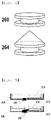
- FIG. 4 is a perspective view of sealing portions according to the present invention.
- each of the sealing portions 260 and 264 may be made of a polymer resin.
- Each of the sealing portions 260 and 264 may be made of a thermoplastic polymer resin or a thermosetting polymer resin, specifically a thermoplastic polymer resin.
- the polymer resin may be an elastomer.
- the sealing portion 260 which is shown at the upper part of FIG. 4 , may be configured as a plug, the radius of the central portion of which is less than the radius of the outer periphery thereof, and the sealing portion 264, which is shown at the lower part of FIG. 4 , may be configured such that a projection, the radius of which is gradually increased and is then abruptly decreased, is formed at a portion of the sealing portion configured to be inserted into the cylindrical secondary battery 200.
- FIG. 5 is a view showing an example in which the through-hole according to the present invention is hermetically sealed using a sealing portion.
- the sealing portion 260 may be inserted through the through-hole in order to hermetically seal the through-hole (the figure shown at the upper part of FIG. 5 ).
- a thermoplastic polymer resin may be injected into the through-hole 250 so as to cover a region at which the negative electrode tab 212 is welded to the cylindrical can 220, whereby a sealing portion 262 may be formed.
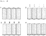
- FIG. 6 is a schematic view showing a process of assembling a cylindrical secondary battery according to the present invention.
- a cylindrical secondary battery is assembled as follows.
- the present invention may provide a battery pack including the cylindrical secondary battery.
- the battery pack may be used as a power source for a device requiring the ability to withstand high temperature, long cycle characteristics, high rate characteristics, etc.
- the device may include a mobile electronic device, a wearable electronic device, a power tool driven by a battery-powered motor, an electric automobile, such as an electric vehicle (EV), a hybrid electric vehicle (HEV), or a plug-in hybrid electric vehicle (PHEV), an electric two-wheeled vehicle, such as an electric bicycle (E-bike) or an electric scooter (E-scooter), an electric golf cart, and an energy storage system.
- EV electric vehicle
- HEV hybrid electric vehicle
- PHEV plug-in hybrid electric vehicle
- E-bike electric bicycle
- E-scooter electric scooter
- the present invention is not limited thereto.
- a bottom portion of a cylindrical secondary battery is provided with a through-hole, which is hermetically sealed using a polymer resin or rubber, and an additional electrolytic solution may be supplied using a syringe even after the through-hole is hermetically sealed.
- the bottom portion of the secondary battery is concave inwards. Even in the case in which pressure in the secondary battery is high, therefore, the bottom portion of the secondary battery is prevented from being deformed. Since a central portion of the bottom portion is concave, the pressure in the secondary battery is uniformly dispersed, whereby sealability of the secondary battery is excellent.
- the bottom portion of the cylindrical secondary battery is perforated, and the sealing portion is added thereto. Perforation is easily and rapidly performed, which is economical.
- the sealing portion is added in the state in which the thickness thereof is minimized, whereby the capacity of a conventional secondary battery is not reduced.
- the sealing portion is made of a thermoplastic polymer resin or rubber.
- the thermoplastic polymer resin or rubber wraps a weld region of a negative electrode tab welded to the inner bottom of the can.
Landscapes
- Chemical & Material Sciences (AREA)
- Chemical Kinetics & Catalysis (AREA)
- Electrochemistry (AREA)
- General Chemical & Material Sciences (AREA)
- Engineering & Computer Science (AREA)
- Manufacturing & Machinery (AREA)
- Inorganic Chemistry (AREA)
- Sealing Battery Cases Or Jackets (AREA)
- Secondary Cells (AREA)
- Filling, Topping-Up Batteries (AREA)
- Connection Of Batteries Or Terminals (AREA)
Abstract
Description
- This application claims the benefit of priority to
Korean Patent Application No. 2019-0169530 filed on December 18, 2019 - The present invention relates to a cylindrical secondary battery provided with a flexible input portion. More particularly, the present invention relates to a cylindrical secondary battery configured such that a hole is provided in a bottom portion of the cylindrical secondary battery manufactured using a metal can and the hole is hermetically sealed using a flexible material, such as a thermoplastic polymer resin or rubber.
- Secondary batteries are classified based on the shape of a battery case. Secondary batteries may be mainly classified into a cylindrical battery having an electrode assembly mounted in a cylindrical metal can, a prismatic battery having an electrode assembly mounted in a prismatic metal can, and a pouch-shaped battery having an electrode assembly mounted in a pouch-shaped case made of an aluminum laminate sheet.
- An electrode assembly mounted in a battery case is a power-generating element that is configured to have a structure including a positive electrode, a negative electrode, and a separator interposed between the positive electrode and the negative electrode and that can be charged and discharged. The electrode assembly is classified as a jelly-roll type electrode assembly, which is configured to have a structure in which a long sheet type positive electrode having an active material applied thereto and a long sheet type negative electrode having an active material applied thereto are wound in the state in which a separator is interposed between the positive electrode and the negative electrode, or a stacked type electrode assembly, which is configured to have a structure in which a plurality of positive electrodes having a predetermined size and a plurality of negative electrodes having a predetermined size are sequentially stacked in the state in which separators are interposed respectively between the positive electrodes and the negative electrodes. Thereamong, the jelly-roll type electrode assembly has advantages in that the jelly-roll type electrode assembly is easy to manufacture and has high energy density per unit weight.
- The jelly-roll type electrode assembly may be mounted in a cylindrical metal can in order to constitute a cylindrical secondary battery. The cylindrical secondary battery is widely used in fields in which a high-capacity secondary battery is necessary, such as electric vehicles.
- Unlike the pouch-shaped battery, the cylindrical secondary battery is activated after assembly thereof. When the cylindrical secondary battery is assembled, the can, which constitutes an outer case, is hermetically sealed. In a process of activating the battery, gas is inevitably generated. The pouch-shaped battery is finally hermetically sealed after gas generated in the battery is discharged to the outside. The secondary battery is not provided with a separate discharge port, through which the gas generated in the battery can be smoothly discharged.
- The cylindrical secondary battery starts to be used in the state in which pressure in the battery already increases. The extent to which an electrolytic solution in the battery is volatilized to the outside due to an increase in pressure in the battery as the result of continuous use thereof is higher than in other kinds of batteries, which leads to reduction in lifespan and deterioration in performance of the battery.
- Patent Document 1 relates to a cylindrical battery including an electrolytic solution injection port, the cylindrical battery being a secondary battery having a structure in which an electrode assembly having a positive electrode/separator/negative electrode structure is mounted in a cylindrical can, wherein a cap assembly is mounted at an upper end portion, which is open, of the can, at least one opening configured to allow a user to inject an electrolytic solution therethrough is formed in the outer surface of the can by perforation, and a sealing member, through which an electrolytic solution injection pin is capable of extending, is forcibly inserted into the opening in order to hermetically seal the opening from the outside.
- In Patent Document 1, 1) it is not easy to perforate the side surface of the cylinder at a uniform position thereof, since the side surface of the cylinder is perforated, 2) technical attention is required to perforate the side surface of the cylinder, and 3) it is necessary to manufacture a separate support portion having a corresponding shape in order to seal a hole provided in the side surface of the cylinder. In the case in which an iron sheet is stretched to manufacture a can in the state in which the iron sheet is perforated in advance, the iron sheet is not uniformly stretched due to the perforated region of the iron sheet. For this reason, the can must be perforated after the can is manufactured. Also, 4) in the case in which several can type secondary batteries are combined to manufacture a battery module, each secondary battery may be caught by a projection of the support portion or it is difficult to pack the secondary batteries in the same shape due to the support portion provided at the side surface of the cylinder. 5) Despite being supported by the separate support portion, load applied to the sealing member may not be uniform or symmetrical, since the sealing member is coupled to the side surface of the cylinder. Furthermore, 6) Patent Document 1 does not concretely disclose a sealing material.
-
Patent Document 2 relates to a secondary battery including an electrode unit having a positive electrode and a negative electrode installed in the state in which an insulation plate is interposed therebetween, a cap assembly connected to the positive electrode of the electrode unit, a can connected to the negative electrode of the electrode unit, the electrode unit being inserted into the can, and an electrolytic solution injection device installed at the can. - The electrolytic solution injection device of
Patent Document 2 includes an injection hole formed in the can, a body installed at the can, the body having a plurality of supply holes connected to the interior of the battery, a valve member inserted into the body so as to connect the injection hole and the supply holes to each other or to disconnect the injection hole and the supply holes from each other, and a pressurization member configured to apply uniform force to the valve member. A spring is used as the pressurization member. - In
Patent Document 2, an opening and closing device using elasticity of the spring is added to a bottom portion of the can. However, there are shortcomings in that 1) the volume necessary in order to provide a physical elastic portion, i.e. the spring, is large, 2) an intrinsic problem in which an electrolytic solution permeates due to a physically moving construction may occur, and 3) installation is complicated. - In the situation in which technology for maximally increasing the capacity of the battery is seriously required, the actually usable volume of the secondary battery is reduced due to the opening and closing device. Consequently, it can be easily recognized that
Patent Document 2 is technology that is very restrictively used or has many disadvantages. - Therefore, it is necessary to develop technology capable of effectively and economically solving problems with the cylindrical secondary battery, such as rapid evaporation of an original electrolytic solution due to initial sealing and activation of the battery, a decrease in lifespan of the battery, and deterioration in performance of the battery. In addition, minimum deformation of a battery module or a battery pack, for which utilization of the secondary battery gradually increases, is a condition necessary to replace a conventional can type battery.
-
- (Patent Document 1)
Korean Patent Application Publication No. 2018-0010389 (2018.01.31 - (Patent Document 2)
Korean Utility Model Application Publication No. 1998-021641 (1998.07.15 - The present invention has been made in view of the above problems, and it is an object of the present invention to provide technology capable of effectively and economically solving problems with a cylindrical secondary battery, such as rapid evaporation of an original electrolytic solution due to initial sealing and activation of the battery, a decrease in lifespan of the battery, and deterioration in performance of the battery.
- To this end, the present invention provides a cylindrical secondary battery that is capable of being hermetically sealed after activation of the cylindrical secondary battery. Specifically, it is an object of the present invention to provide a cylindrical secondary battery provided with a new and flexible input portion configured such that 1) it is possible to supply an additional electrolytic solution even after hermetic sealing, 2) performance of hermetic sealing is excellent, 3) there is little compatibility problem due to deformation of a case even in the case in which the cylindrical secondary battery is used in a conventional battery module or a conventional battery pack, 4) it is possible to easily and economically manufacture the cylindrical secondary battery, and 5) it is possible to prevent a decrease in capacity of a conventional secondary battery due to introduction of technology.
- In order to accomplish the above object, a cylindrical secondary battery according to the present invention includes a cylindrical can -having a circular bottom portion and a cylinder-shaped outer wall connected to an outer circumference of the bottom portion, a jelly-roll type electrode assembly received in the cylindrical can, the jelly-roll type electrode assembly having a structure in which a positive electrode and a negative electrode are wound in the state in which a separator is interposed between the positive electrode and the negative electrode, and a cap assembly configured to hermetically seal the cylindrical can, wherein a through-hole is formed in a portion of the bottom portion of the cylindrical can, the through-hole being hermetically sealed by a sealing portion.
- The bottom portion may be formed so as to have a curved surface that is concave inwardly of the cylindrical battery, and the center of the bottom portion may include a flat portion.
- The bottom portion may be configured such that the radius of curvature of the concavely curved surface is increased from the outer periphery to the center of the bottom portion.
- The through-hole may be disposed at the center of the bottom portion of the cylindrical can. Specifically, the through-hole may be disposed at a central portion of the bottom portion of the cylindrical can excluding a region of the bottom portion to which a negative electrode tab is welded.
- The detailed shape of the through-hole is not restricted. For example, the shape of through-hole may be a restoratively circular shape, and may be variously changed as needed.
- The sealing portion may be made of a polymer resin. The polymer resin of the cylindrical secondary battery may be a thermoplastic polymer resin or a thermosetting polymer resin, specifically a thermoplastic polymer resin. Concretely, the polymer resin may be an elastomer.
- As a nonrestrictive example of the sealing portion, the sealing portion may be configured as a plug, the radius of a central portion of which is less than the radius of the outer periphery thereof.
- The plug may be configured such that a projection, the radius of which is gradually increased and is then abruptly decreased, is formed at a portion of the plug configured to be inserted into the cylindrical secondary battery.
- In another aspect, the present invention provides a method of manufacturing a cylindrical secondary battery. The method of manufacturing the cylindrical secondary battery includes:
- 1) forming a through-hole in a bottom portion of a cylindrical secondary battery;
- 2) receiving an electrode assembly and assembling a cap assembly;
- 3) disposing the cylindrical battery assembled in step 2) such that the bottom portion faces upwards;
- 4) injecting an electrolytic solution through the through-hole and activating the cylindrical battery or initially charging and discharging the cylindrical battery; and
- 5) hermetically sealing the through-hole using a sealing portion.
- The method may further include injecting an additional electrolytic solution between step 4) and step 5), and the hermetically sealing step of step 5) may include hermetically sealing the through-hole using a plug, the radius of a central portion of which is less than the radius of the outer periphery thereof.
- The hermetically sealing step of step 5) may include injecting a thermoplastic polymer resin into the through-hole so as to cover a negative electrode tab region welded to the cylindrical can in order to hermetically seal the through-hole.
- The present invention may be provided through various combinations of the technical solutions.
-
-
FIG. 1 is a vertical sectional view of a conventional general cylindrical secondary battery. -
FIG. 2 is a sectional view of a cylindrical secondary battery provided with a through-hole according to an embodiment of the present invention and the cylindrical secondary battery in the state in which the through-hole is hermetically sealed. -
FIG. 3 is a sectional view showing the lower parts of three kinds of cylindrical secondary batteries according to the present invention, each of which is provided with a through-hole. -
FIG. 4 is a perspective view of sealing portions according to the present invention. -
FIG. 5 is a view showing an example in which the through-hole according to the present invention is hermetically sealed using a sealing portion. -
FIG. 6 is a schematic view showing a process of assembling a cylindrical secondary battery according to the present invention. - Now, preferred embodiments of the present invention will be described in detail with reference to the accompanying drawings such that the preferred embodiments of the present invention can be easily implemented by a person having ordinary skill in the art to which the present invention pertains. In describing the principle of operation of the preferred embodiments of the present invention in detail, however, a detailed description of known functions and configurations incorporated herein will be omitted when the same may obscure the subject matter of the present invention.
- In addition, the same reference numbers will be used throughout the drawings to refer to parts that perform similar functions or operations. In the case in which one part is said to be connected to another part in the specification, not only may the one part be directly connected to the other part, but also, the one part may be indirectly connected to the other part via a further part. In addition, that a certain element is included does not mean that other elements are excluded, but means that such elements may be further included unless mentioned otherwise.
- Hereinafter, embodiments of the present invention will be described in detail with reference to the accompanying drawings.
-
FIG. 1 is a vertical sectional view showing a conventional general cylindrical secondary battery. Referring toFIG. 1 , the cylindricalsecondary battery 100 is configured such that anelectrode assembly 110 is received in acylindrical can 120, acap assembly 130 is located at the upper part of the cylindrical can, and the cylindricalsecondary battery 100 is hermetically sealed by a crimpinggasket 133. - The
cap assembly 130 includes a ventingmember 132 located at the lower part of atop cap 131 while wrapping the outer circumference of the top cap and a current interruptmember 135 located at the lower part of the venting member 123 while contacting a central portion of the ventingmember 132. Alower gasket 134 configured to prevent the ventingmember 132 and the current interruptmember 135 from contacting each other at the portion of the ventingmember 132 other than the central portion thereof is located at the outer periphery of the current interruptmember 135. - A
positive electrode tab 111 of theelectrode assembly 110 is attached to the lower surface of the current interruptmember 135 such that thecap assembly 130 serves as a positive electrode terminal, and anegative electrode tab 112 is coupled to the bottom portion of the cylindrical can 120 by welding. -
FIG. 2 is a sectional view of a cylindricalsecondary battery 200 provided with a through-hole according to an embodiment of the present invention and the cylindricalsecondary battery 200 in the state in which the through-hole is hermetically sealed. - Referring to
FIG. 2 , the cylindricalsecondary battery 200 according to the present invention is a cylindricalsecondary battery 200 including acylindrical can 220 constituted by a circular bottom portion and a cylinder-shaped outer wall connected to the outer circumference of the bottom portion, a jelly-rolltype electrode assembly 210 received in thecylindrical can 220, the jelly-roll type electrode assembly having a structure in which a positive electrode, a negative electrode, and a separator interposed between the positive electrode and the negative electrode are wound, and acap assembly 230 configured to hermetically seal thecylindrical can 220. A through-hole 250 is formed in a portion of the bottom portion of thecylindrical can 200, and the through-hole 250 is hermetically sealed by a sealingportion 260. -
FIG. 3 is a sectional view showing the lower parts of three kinds of cylindrical secondary batteries according to the present invention, each of which is provided with a through-hole. - Referring to
FIG. 3 , the bottom portion of the secondary battery may be flat (the first figure ofFIG. 3 ) or may be formed so as to have a curved surface that is concave inwards, wherein the radius of curvature of the concavely curved surface may be increased from the outer periphery to the center of the bottom portion (the second figure ofFIG. 3 ). Alternatively, a central portion of the bottom portion may include a flat portion (the third figure ofFIG. 3 ). - It can be seen from
FIGS. 2 and3 that the through-hole 250 is disposed at the central portion of the bottom portion of the cylindrical can 220 excluding a region of the bottom portion to which anegative electrode tab 212 is welded. -
FIG. 4 is a perspective view of sealing portions according to the present invention. - Referring to
FIG. 4 , each of the sealingportions portions - The sealing
portion 260, which is shown at the upper part ofFIG. 4 , may be configured as a plug, the radius of the central portion of which is less than the radius of the outer periphery thereof, and the sealingportion 264, which is shown at the lower part ofFIG. 4 , may be configured such that a projection, the radius of which is gradually increased and is then abruptly decreased, is formed at a portion of the sealing portion configured to be inserted into the cylindricalsecondary battery 200. -
FIG. 5 is a view showing an example in which the through-hole according to the present invention is hermetically sealed using a sealing portion. Referring toFIG. 5 , the sealingportion 260 may be inserted through the through-hole in order to hermetically seal the through-hole (the figure shown at the upper part ofFIG. 5 ). Alternatively, in a hermetically sealing step, a thermoplastic polymer resin may be injected into the through-hole 250 so as to cover a region at which thenegative electrode tab 212 is welded to thecylindrical can 220, whereby a sealingportion 262 may be formed. -
FIG. 6 is a schematic view showing a process of assembling a cylindrical secondary battery according to the present invention. - In the present invention, a cylindrical secondary battery is assembled as follows.
- A step of forming a through-hole in a bottom portion of a cylindrical secondary battery, a step of receiving an electrode assembly and assembling a cap assembly (1 of
FIG. 6 ), a step of turning the cylindrical secondary battery such that the bottom portion of the cylindrical secondary battery to which with the cap assembly is assembled faces upwards and the cap assembly faces downwards, injecting an electrolytic solution through the through-hole, and activating the cylindrical secondary battery or initially charging and discharging the cylindrical secondary battery (2 ofFIG. 6 ), and a step of hermetically sealing the through-hole using a sealing portion (3 ofFIG. 6 ) are performed, whereby a final cylindrical secondary battery is completed (4 ofFIG. 6 ). - In addition, the present invention may provide a battery pack including the cylindrical secondary battery.
- Specifically, the battery pack may be used as a power source for a device requiring the ability to withstand high temperature, long cycle characteristics, high rate characteristics, etc. Specific examples of the device may include a mobile electronic device, a wearable electronic device, a power tool driven by a battery-powered motor, an electric automobile, such as an electric vehicle (EV), a hybrid electric vehicle (HEV), or a plug-in hybrid electric vehicle (PHEV), an electric two-wheeled vehicle, such as an electric bicycle (E-bike) or an electric scooter (E-scooter), an electric golf cart, and an energy storage system. However, the present invention is not limited thereto.
- The structure and manufacturing method of the device are well known in the art to which the present invention pertains, and thus a detailed description thereof will be omitted.
- Those skilled in the art to which the present invention pertains will appreciate that various applications and modifications are possible within the category of the present invention based on the above description.
-
- 100, 200: Cylindrical secondary batteries
- 110, 210: Electrode assemblies
- 111: Positive electrode tab
- 112, 212: Negative electrode tabs
- 120, 220: Cylindrical cans
- 130, 230: Cap assemblies
- 131: Top cap
- 132: Venting member
- 133: Crimping gasket
- 134: Lower gasket
- 135: Current interrupt member
- 250: Through-hole
- 260, 262, 264: Sealing portions
- As is apparent from the above description, in the present invention, a bottom portion of a cylindrical secondary battery is provided with a through-hole, which is hermetically sealed using a polymer resin or rubber, and an additional electrolytic solution may be supplied using a syringe even after the through-hole is hermetically sealed.
- In addition, the bottom portion of the secondary battery is concave inwards. Even in the case in which pressure in the secondary battery is high, therefore, the bottom portion of the secondary battery is prevented from being deformed. Since a central portion of the bottom portion is concave, the pressure in the secondary battery is uniformly dispersed, whereby sealability of the secondary battery is excellent.
- In addition, since a sealing portion is added to the central portion of the bottom portion of the cylindrical secondary battery, there is little compatibility problem due to deformation of a case even in the case in which the cylindrical secondary battery is used in a conventional battery module or a conventional battery pack.
- In addition, the bottom portion of the cylindrical secondary battery is perforated, and the sealing portion is added thereto. Perforation is easily and rapidly performed, which is economical.
- In addition, the sealing portion is added in the state in which the thickness thereof is minimized, whereby the capacity of a conventional secondary battery is not reduced.
- In addition, the sealing portion is made of a thermoplastic polymer resin or rubber. In the case in which a portion of the thermoplastic polymer resin or rubber is injected into a can in order to hermetically seal the can, therefore, the thermoplastic polymer resin or rubber wraps a weld region of a negative electrode tab welded to the inner bottom of the can. As a result, it is possible to prevent the weld region in the can from being damaged even in the case in which the cylindrical secondary battery is used for a vehicle, to which strong external impact and vibration are applied.
Claims (15)
- A cylindrical secondary battery comprising:a cylindrical can having a circular bottom portion and a cylinder-shaped outer wall connected to an outer circumference of the bottom portion;a jelly-roll type electrode assembly received in the cylindrical can, the jelly-roll type electrode assembly having a structure in which a positive electrode and a negative electrode are wound in a state in which a separator is interposed between the positive electrode and the negative electrode; anda cap assembly configured to hermetically seal the cylindrical can, whereina through-hole is formed in a portion of the bottom portion of the cylindrical can, the through-hole being hermetically sealed by a sealing portion.
- The cylindrical secondary battery according to claim 1, wherein the bottom portion is formed so as to have a curved surface that is concave inwardly of the cylindrical battery.
- The cylindrical secondary battery according to claim 2, wherein a center of the bottom portion comprises a flat portion.
- The cylindrical secondary battery according to claim 2, wherein the bottom portion is configured such that a radius of curvature of the concavely curved surface is increased from an outer periphery to a center of the bottom portion.
- The cylindrical secondary battery according to claim 1, wherein the through-hole is disposed at a central portion of the bottom portion of the cylindrical can excluding a region of the bottom portion to which a negative electrode tab is welded.
- The cylindrical secondary battery according to claim 5, wherein the through-hole is circular.
- The cylindrical secondary battery according to claim 1, wherein the sealing portion is made of a polymer resin.
- The cylindrical secondary battery according to claim 7, wherein the polymer resin is a thermoplastic polymer resin.
- The cylindrical secondary battery according to claim 7, wherein the polymer resin is an elastomer.
- The cylindrical secondary battery according to claim 1, wherein the sealing portion is configured as a plug, a radius of a central portion of which is less than a radius of an outer periphery thereof.
- The cylindrical secondary battery according to claim 10, wherein the plug is configured such that a projection, a radius of which is gradually increased and is then abruptly decreased, is formed at a portion of the plug configured to be inserted into the cylindrical secondary battery.
- A method of manufacturing the cylindrical secondary battery according to any one of claims 1 to 11, the method comprising:1) forming a through-hole in a bottom portion of a cylindrical secondary battery;2) receiving an electrode assembly and assembling a cap assembly;3) disposing the cylindrical battery assembled in step 2) such that the bottom portion faces upwards;4) injecting an electrolytic solution through the through-hole and activating the cylindrical battery or initially charging and discharging the cylindrical battery; and5) hermetically sealing the through-hole using a sealing portion.
- The method according to claim 12, further comprising injecting an additional electrolytic solution between step 4) and step 5).
- The method according to claim 12, wherein the hermetically sealing step of step 5) comprises hermetically sealing the through-hole using a plug, a radius of a central portion of which is less than a radius of an outer periphery thereof.
- The method according to claim 12, wherein the hermetically sealing step of step 5) comprises injecting a thermoplastic polymer resin into the through-hole so as to cover a negative electrode tab region welded to the cylindrical can in order to hermetically seal the through-hole.
Applications Claiming Priority (2)
| Application Number | Priority Date | Filing Date | Title |
|---|---|---|---|
| KR1020190169530A KR102752699B1 (en) | 2019-12-18 | 2019-12-18 | Cylindrical secondary battery comprising flexible input port |
| PCT/KR2020/017773 WO2021125654A1 (en) | 2019-12-18 | 2020-12-07 | Cylindrical secondary battery having flexible input part |
Publications (2)
| Publication Number | Publication Date |
|---|---|
| EP4080649A1 true EP4080649A1 (en) | 2022-10-26 |
| EP4080649A4 EP4080649A4 (en) | 2023-01-25 |
Family
ID=76478467
Family Applications (1)
| Application Number | Title | Priority Date | Filing Date |
|---|---|---|---|
| EP20901473.7A Pending EP4080649A4 (en) | 2019-12-18 | 2020-12-07 | CYLINDRICAL SECONDARY BATTERY HAVING A FLEXIBLE INPUT PART |
Country Status (6)
| Country | Link |
|---|---|
| US (1) | US20220399564A1 (en) |
| EP (1) | EP4080649A4 (en) |
| JP (1) | JP7376003B2 (en) |
| KR (1) | KR102752699B1 (en) |
| CN (1) | CN114600288B (en) |
| WO (1) | WO2021125654A1 (en) |
Families Citing this family (2)
| Publication number | Priority date | Publication date | Assignee | Title |
|---|---|---|---|---|
| KR20230085070A (en) * | 2021-12-06 | 2023-06-13 | 도요타 지도샤(주) | Secondary battery |
| WO2024136617A1 (en) * | 2022-12-23 | 2024-06-27 | 주식회사 엘지에너지솔루션 | Cylindrical secondary battery and method for manufacturing same |
Family Cites Families (18)
| Publication number | Priority date | Publication date | Assignee | Title |
|---|---|---|---|---|
| KR100205407B1 (en) | 1996-09-18 | 1999-07-01 | 구자홍 | Shadow Mask for Cathode Ray Tube |
| JPH11224651A (en) * | 1998-02-06 | 1999-08-17 | Awa Eng Co | Cylindrical battery filled with non-aqueous electrolyte and manufacturing method thereof |
| JP2005251738A (en) | 2004-02-03 | 2005-09-15 | Toshiba Corp | Non-aqueous electrolyte secondary battery and method for producing non-aqueous electrolyte secondary battery |
| KR100686831B1 (en) * | 2005-05-16 | 2007-02-26 | 삼성에스디아이 주식회사 | Secondary Battery and Manufacturing Method of Secondary Battery Using the Same |
| KR101243556B1 (en) * | 2006-05-08 | 2013-03-20 | 삼성에스디아이 주식회사 | Lithium rechargeable battery and Method of making the same |
| KR100856833B1 (en) * | 2006-10-20 | 2008-09-05 | 주식회사 네스캡 | Electric energy storage device and manufacturing method thereof |
| TW201027825A (en) * | 2009-01-05 | 2010-07-16 | High Tech Battery Inc | Low pressure mould packaging structure of a fuel cell |
| CN104094450B (en) * | 2012-02-22 | 2016-11-16 | 日立汽车系统株式会社 | Square secondary battery |
| KR101543494B1 (en) * | 2012-05-31 | 2015-08-10 | 주식회사 엘지화학 | Pouch typed battery having an electrolyte injection and/or exhaust hole |
| US9490079B2 (en) * | 2014-03-28 | 2016-11-08 | Cooper Technologies Company | Electrochemical energy storage device with flexible metal contact current collector and methods of manufacture |
| KR101663988B1 (en) * | 2015-02-06 | 2016-10-11 | 주식회사 비츠로셀 | battery for enhancing electrolyte filling efficiency |
| US20170027811A1 (en) * | 2015-07-31 | 2017-02-02 | Michael Edward Thomas | Sexual Stimulation Device Base |
| KR102261711B1 (en) | 2016-07-21 | 2021-06-08 | 주식회사 엘지에너지솔루션 | Cylindrical Battery Having Electrolyte Injection-hole |
| KR102265221B1 (en) * | 2017-03-20 | 2021-06-16 | (주)엘지에너지솔루션 | Preparation Method of Battery Cell for Improving Wetting Property of Electrolyte |
| KR102285978B1 (en) * | 2017-04-14 | 2021-08-04 | 주식회사 엘지에너지솔루션 | Secondry battery and manufacturing method for the same |
| KR102662717B1 (en) * | 2017-09-20 | 2024-05-03 | 주식회사 엘지에너지솔루션 | Cylindrical Secondary Battery Consisting of Curved Bottom |
| KR102702546B1 (en) * | 2018-02-14 | 2024-09-05 | 삼성에스디아이 주식회사 | Electrode assembly and secondary battery comprising the same |
| KR102538094B1 (en) * | 2018-04-17 | 2023-05-26 | 삼성에스디아이 주식회사 | Rechargeable battery |
-
2019
- 2019-12-18 KR KR1020190169530A patent/KR102752699B1/en active Active
-
2020
- 2020-12-07 JP JP2022523240A patent/JP7376003B2/en active Active
- 2020-12-07 CN CN202080073329.4A patent/CN114600288B/en active Active
- 2020-12-07 EP EP20901473.7A patent/EP4080649A4/en active Pending
- 2020-12-07 WO PCT/KR2020/017773 patent/WO2021125654A1/en not_active Ceased
- 2020-12-07 US US17/772,047 patent/US20220399564A1/en active Pending
Also Published As
| Publication number | Publication date |
|---|---|
| WO2021125654A1 (en) | 2021-06-24 |
| EP4080649A4 (en) | 2023-01-25 |
| KR102752699B1 (en) | 2025-01-10 |
| KR20210077968A (en) | 2021-06-28 |
| US20220399564A1 (en) | 2022-12-15 |
| CN114600288B (en) | 2025-09-12 |
| JP2022552858A (en) | 2022-12-20 |
| JP7376003B2 (en) | 2023-11-08 |
| CN114600288A (en) | 2022-06-07 |
Similar Documents
| Publication | Publication Date | Title |
|---|---|---|
| CN110352511B (en) | Cylindrical battery cell without crimp | |
| EP3188280B1 (en) | Cap assembly and secondary battery including the same | |
| CN107221624B (en) | Rechargeable battery | |
| US20240097291A1 (en) | Cylindrical lithium ion secondary battery | |
| EP2696429B1 (en) | Compressible core for a wound electrode assembly | |
| US7691530B2 (en) | Cylindrical lithium secondary battery | |
| CN114175380B (en) | Secondary battery | |
| CN103959512A (en) | Secondary battery manufacturing method and secondary battery | |
| KR101549174B1 (en) | Secondary battery and method for manufacturing the same | |
| JP2006019292A (en) | Secondary battery and method for manufacturing secondary battery | |
| EP4191760B1 (en) | Secondary battery | |
| KR102761907B1 (en) | Secondary Battery | |
| EP4080649A1 (en) | Cylindrical secondary battery having flexible input part | |
| KR20190032019A (en) | Pouch-Type Secondary Battery Comprising Venting Part | |
| CN111566846B (en) | Secondary battery | |
| KR101134122B1 (en) | Large capacity secondary battery | |
| EP4235929B1 (en) | Secondary battery | |
| KR102323809B1 (en) | The Apparatus For Venting And The Method For Manufacturing Thereof | |
| US20060068273A1 (en) | Cap assembly having a vent plate and rechargeable battery with same | |
| KR20190131794A (en) | The Secondary Battery | |
| JP4827442B2 (en) | Assembled battery | |
| US20250253489A1 (en) | Cylindrical rechargeable battery | |
| JP2002164025A (en) | Prismatic rechargeable battery | |
| KR101279408B1 (en) | Method for manufacturing secondary battery | |
| CN223436651U (en) | Battery cell and battery module including the battery cell |
Legal Events
| Date | Code | Title | Description |
|---|---|---|---|
| STAA | Information on the status of an ep patent application or granted ep patent |
Free format text: STATUS: THE INTERNATIONAL PUBLICATION HAS BEEN MADE |
|
| PUAI | Public reference made under article 153(3) epc to a published international application that has entered the european phase |
Free format text: ORIGINAL CODE: 0009012 |
|
| STAA | Information on the status of an ep patent application or granted ep patent |
Free format text: STATUS: REQUEST FOR EXAMINATION WAS MADE |
|
| 17P | Request for examination filed |
Effective date: 20220419 |
|
| AK | Designated contracting states |
Kind code of ref document: A1 Designated state(s): AL AT BE BG CH CY CZ DE DK EE ES FI FR GB GR HR HU IE IS IT LI LT LU LV MC MK MT NL NO PL PT RO RS SE SI SK SM TR |
|
| REG | Reference to a national code |
Ref country code: DE Ref legal event code: R079 Free format text: PREVIOUS MAIN CLASS: H01M0050100000 Ipc: H01M0010040000 |
|
| A4 | Supplementary search report drawn up and despatched |
Effective date: 20221223 |
|
| RIC1 | Information provided on ipc code assigned before grant |
Ipc: H01M 50/645 20210101ALI20221219BHEP Ipc: H01M 50/627 20210101ALI20221219BHEP Ipc: H01M 50/609 20210101ALI20221219BHEP Ipc: H01M 50/107 20210101ALI20221219BHEP Ipc: H01M 10/04 20060101AFI20221219BHEP |
|
| DAV | Request for validation of the european patent (deleted) | ||
| DAX | Request for extension of the european patent (deleted) | ||
| STAA | Information on the status of an ep patent application or granted ep patent |
Free format text: STATUS: EXAMINATION IS IN PROGRESS |
|
| 17Q | First examination report despatched |
Effective date: 20250513 |